WO2016186209A1 - 二次電池用の電極および二次電池の製造方法と製造装置 - Google Patents
二次電池用の電極および二次電池の製造方法と製造装置 Download PDFInfo
- Publication number
- WO2016186209A1 WO2016186209A1 PCT/JP2016/065076 JP2016065076W WO2016186209A1 WO 2016186209 A1 WO2016186209 A1 WO 2016186209A1 JP 2016065076 W JP2016065076 W JP 2016065076W WO 2016186209 A1 WO2016186209 A1 WO 2016186209A1
- Authority
- WO
- WIPO (PCT)
- Prior art keywords
- die head
- current collector
- forming
- active material
- secondary battery
- Prior art date
- Legal status (The legal status is an assumption and is not a legal conclusion. Google has not performed a legal analysis and makes no representation as to the accuracy of the status listed.)
- Ceased
Links
Images





Classifications
-
- H—ELECTRICITY
- H01—ELECTRIC ELEMENTS
- H01M—PROCESSES OR MEANS, e.g. BATTERIES, FOR THE DIRECT CONVERSION OF CHEMICAL ENERGY INTO ELECTRICAL ENERGY
- H01M4/00—Electrodes
- H01M4/02—Electrodes composed of, or comprising, active material
- H01M4/04—Processes of manufacture in general
- H01M4/0402—Methods of deposition of the material
- H01M4/0404—Methods of deposition of the material by coating on electrode collectors
-
- H—ELECTRICITY
- H01—ELECTRIC ELEMENTS
- H01M—PROCESSES OR MEANS, e.g. BATTERIES, FOR THE DIRECT CONVERSION OF CHEMICAL ENERGY INTO ELECTRICAL ENERGY
- H01M4/00—Electrodes
- H01M4/02—Electrodes composed of, or comprising, active material
- H01M4/13—Electrodes for accumulators with non-aqueous electrolyte, e.g. for lithium-accumulators; Processes of manufacture thereof
- H01M4/139—Processes of manufacture
-
- H—ELECTRICITY
- H01—ELECTRIC ELEMENTS
- H01M—PROCESSES OR MEANS, e.g. BATTERIES, FOR THE DIRECT CONVERSION OF CHEMICAL ENERGY INTO ELECTRICAL ENERGY
- H01M4/00—Electrodes
- H01M4/02—Electrodes composed of, or comprising, active material
- H01M4/13—Electrodes for accumulators with non-aqueous electrolyte, e.g. for lithium-accumulators; Processes of manufacture thereof
- H01M4/139—Processes of manufacture
- H01M4/1391—Processes of manufacture of electrodes based on mixed oxides or hydroxides, or on mixtures of oxides or hydroxides, e.g. LiCoOx
-
- Y—GENERAL TAGGING OF NEW TECHNOLOGICAL DEVELOPMENTS; GENERAL TAGGING OF CROSS-SECTIONAL TECHNOLOGIES SPANNING OVER SEVERAL SECTIONS OF THE IPC; TECHNICAL SUBJECTS COVERED BY FORMER USPC CROSS-REFERENCE ART COLLECTIONS [XRACs] AND DIGESTS
- Y02—TECHNOLOGIES OR APPLICATIONS FOR MITIGATION OR ADAPTATION AGAINST CLIMATE CHANGE
- Y02E—REDUCTION OF GREENHOUSE GAS [GHG] EMISSIONS, RELATED TO ENERGY GENERATION, TRANSMISSION OR DISTRIBUTION
- Y02E60/00—Enabling technologies; Technologies with a potential or indirect contribution to GHG emissions mitigation
- Y02E60/10—Energy storage using batteries
Definitions
- the present invention relates to a secondary battery electrode, a secondary battery manufacturing method and a manufacturing apparatus.
- Secondary batteries are widely used not only as power sources for portable devices such as mobile phones, digital cameras, and laptop computers, but also as power sources for vehicles and homes.
- the secondary battery has become an energy storage device indispensable for daily life.
- Secondary batteries can be broadly classified into wound type and stacked type.
- the battery element of the wound secondary battery has a structure in which a long positive electrode sheet and a long negative electrode sheet are wound a plurality of times in a state of being overlapped while being separated by a separator.
- a battery element of a stacked secondary battery has a structure in which a plurality of positive electrode sheets and a plurality of negative electrode sheets are alternately and repeatedly stacked while being separated by a separator.
- the positive electrode sheet and the negative electrode sheet are coated with an active material to connect an electrode terminal to an application part in which an active material (including a mixture containing a binder or a conductive material) is applied to a current collector. And an uncoated part.
- one end of the positive electrode terminal is electrically connected to the uncoated portion of the positive electrode sheet, and the other end is drawn out of the outer container (exterior case).
- the battery element is enclosed in the outer container so that one end of the negative electrode terminal is electrically connected to the uncoated portion of the negative electrode sheet and the other end is drawn out of the outer container.
- an electrolytic solution is sealed together with the battery element.
- Secondary batteries have a tendency to increase in capacity year by year. Along with this, the heat generated in the event of a short circuit becomes larger and the danger increases. Therefore, battery safety measures are becoming more and more important.
- a safety measure there is a configuration in which an insulating member is formed at the boundary between the coated portion and the uncoated portion in order to prevent a short circuit between the positive electrode and the negative electrode.
- an insulating member is formed at the boundary between the coated portion and the uncoated portion in order to prevent a short circuit between the positive electrode and the negative electrode.
- the energy density per volume decreases, the electrical characteristics vary due to the fact that the battery element cannot be pressed evenly, There is a risk that the quality of the battery may be degraded, such as degradation of cycle characteristics. Therefore, in Patent Documents 1 and 2, the end portion of the active material layer is partially thinned, and an insulating member is disposed between the thinned portion and the uncoated portion.
- Patent Documents 1 and 2 in order to form a thin portion of the active material layer, a shim is disposed in the discharge port of the die head that discharges the active material onto the current collector, and the active material is discharged from the discharge port by the shim.
- a configuration is adopted in which a thick portion and a thin portion can be formed at the same time by generating a portion where the discharge thickness of the substance is thin.
- a thin sheet-shaped current collector is discharged from the die head toward the relatively moving current collector while moving the long sheet-shaped current collector relative to the position facing the die head.
- a die head in which shims are arranged in the discharge ports as shown in Patent Documents 1 and 2 can be used.
- a shim is not used.
- the thin portion must be formed by controlling the discharge amount of the active material from. This control is very complicated, and it is not easy to accurately form a thin portion having a desired thickness.
- an object of the present invention is to solve the above-described problems and easily and accurately form a thin-walled portion when sequentially forming a thin-walled portion and a thick-walled portion of the active material along the relative movement direction of the current collector.
- An object of the present invention is to provide a secondary battery electrode, a secondary battery manufacturing method, and a manufacturing apparatus.
- the step of forming the coating portion is performed at a position where the die head is brought close to the current collector.
- the slurry containing the active material is discharged from the die head to form a thin portion where the thickness of the active material layer is thin, and the die head is separated from the current collector than the step of forming the thin portion, And a step of discharging the slurry from the die head at a discharge pressure larger than the step of forming the thin portion to form a thick portion having a thick active material layer.
- the discharge pressure is changed in accordance with the change in the distance between the die head and the current collector.
- the step of forming the application part is performed by bringing the die head close to the current collector.
- the slurry containing the active material is discharged from the die head at a position where the active material layer is thin and the die head is separated from the current collector more than the step of forming the thin portion.
- the flow rate is changed in accordance with the change in the distance between the die head and the current collector.
- An apparatus for producing an electrode for a secondary battery having an application part in which an active material layer is formed on a current collector of the present invention a die head for discharging a slurry containing the active material toward the current collector, Relative moving means for relatively moving the electric body at a position facing the die head, die head moving means capable of moving the die head closer to and away from the current collector relatively moved by the relative moving means, and die head movement Based on the detection result of the movement amount detection means, the movement amount detection means for detecting the displacement of the die head by the means, the pump for supplying slurry to the die head, the coating valve interposed between the die head and the pump, and the movement amount detection means.
- the slurry is discharged from the die head with a small discharge pressure when it is close to the electric body, and large when the die head is away from the current collector.
- the control means for controlling the pump or the movement amount detection means so that the slurry is discharged from the die head at the discharge pressure, the slurry is applied to the die head at a small flow rate when the die head is in a position close to the current collector.
- a control means for controlling the pump so as to supply slurry to the die head at a large flow rate when the die head is at a position away from the current collector.
- the thin portion can be easily formed with high accuracy when the thin portion and the thick portion of the active material are sequentially formed along the relative movement direction of the current collector.
- FIG. 1B is a sectional view taken along line AA in FIG. 1A. It is an enlarged plan view which shows the principal part of the positive electrode of the secondary battery shown to FIG. 1A and 1B. It is an expanded sectional view of Drawing 2A. It is a top view which shows the manufacturing process of the positive electrode of the secondary battery of this invention. It is a top view which shows the process following FIG. 3 of the manufacturing process of the positive electrode of the secondary battery of this invention. It is a top view which shows the process following FIG. 4 of the manufacturing process of the positive electrode of the secondary battery of this invention. It is a top view which shows the positive electrode manufactured by the process shown to FIG. 5A.
- FIG. 7A It is the schematic which shows typically an example of the apparatus used for the intermittent application
- FIG. 1A is a plan view seen from above perpendicular to the main surface (flat surface) of the secondary battery
- FIG. 1B is a cross-sectional view taken along line AA of FIG. 1A
- 2A is an enlarged plan view of the main part of the positive electrode
- FIG. 2B is an enlarged cross-sectional view thereof.
- the lithium ion secondary battery 1 of the present invention includes an electrode laminate (battery element) 17 in which a plurality of positive electrodes (positive electrode sheets) 2 and negative electrodes (negative electrode sheets) 3 are alternately laminated via separators 4. Yes.
- the electrode laminate 17 is housed in an exterior container made of the flexible film 6 together with the electrolytic solution 5.
- One end of the positive electrode terminal 7 is connected to the positive electrode 2 of the electrode laminate 17, and one end of the negative electrode terminal 8 is connected to the negative electrode 3.
- the other end side of the positive electrode terminal 7 and the other end side of the negative electrode terminal 8 are each drawn out of the flexible film 6.
- each layer constituting the electrode laminate 17 (a layer located in an intermediate portion in the thickness direction) is not shown, and the electrolytic solution 5 is shown.
- the positive electrode 2, the negative electrode 3, and the separator 4 are illustrated so as not to be in contact with each other.
- the positive electrode 2 includes a positive electrode current collector (positive electrode current collector) 9 and a positive electrode active material layer (positive electrode active material layer) 10 applied to the positive electrode current collector 9.
- a positive electrode current collector positive electrode current collector
- a positive electrode active material layer positive electrode active material layer
- an application portion where the positive electrode active material layer 10 is formed and an unapplied portion where the positive electrode active material layer 10 is not formed are located side by side along the longitudinal direction.
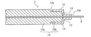
- the positive electrode active material layer 10 on both surfaces of the positive electrode current collector 9 of the present embodiment includes a thick portion 10a and a thin portion 10b.
- the negative electrode 3 includes a negative electrode current collector (negative electrode current collector) 11 and a negative electrode active material layer (negative electrode active material layer) 12 applied to the negative electrode current collector 11.
- the coated portion and the uncoated portion are positioned side by side along the longitudinal direction.
- Each uncoated portion of the positive electrode 2 and the negative electrode 3 is used as a tab for connecting to an electrode terminal (positive electrode terminal 7 or negative electrode terminal 8).
- the positive electrode tabs (positive electrode current collector 9) of the positive electrode 2 are gathered on the positive electrode terminal 7 and connected together with the positive electrode terminal 7 by ultrasonic welding or the like.
- the negative electrode tabs (negative electrode current collector 11) of the negative electrode 3 are gathered on the negative electrode terminal 8 and connected together with the negative electrode terminal 8 by ultrasonic welding or the like.
- the other end portion of the positive electrode terminal 7 and the other end portion of the negative electrode terminal 8 are drawn out of the exterior container made of the flexible film 6, respectively.
- the boundary between the thin portion 10 b of the coated portion where the positive electrode active material layer 10 is formed and the uncoated portion where the positive electrode active material layer 10 is not formed is straddled.
- An insulating member 14 for preventing a short circuit with the negative electrode terminal 8 is disposed so as to cover the portion 13 (which coincides with the terminal position of the positive electrode active material layer 10).
- the sum of the thickness of the thin portion 10 b and the thickness of the insulating member 14 in the portion where the insulating member 14 is located on the thin portion 10 b is smaller than the average thickness of the thick portion 10 a of the positive electrode active material layer 10.
- the portion of the positive electrode 2 where the insulating member 14 is disposed is not thicker than the other portions, so that the decrease in energy density per volume can be suppressed and the battery element can be pressed evenly in order to fix it. Therefore, it is possible to suppress deterioration in battery quality such as variation in electrical characteristics and deterioration in cycle characteristics.
- the external dimension of the application part (negative electrode active material layer 12) of the negative electrode 3 is larger than the external dimension of the application part (positive electrode active material layer 10) of the positive electrode 2, and is smaller than or equal to the external dimension of the separator 4.
- a negative electrode active material layer 12 having a uniform thickness not having a thin portion is formed on both surfaces of a negative electrode current collector 11, and no insulating member 14 is provided.
- examples of the active material constituting the positive electrode active material layer 10 include LiCoO 2 , LiNiO 2 , LiNi (1-x) CoO 2 , and LiNi x (CoAl) (1-x) O 2. , Li 2 MO 3 -LiMO 2 , LiNi 1/3 Co 1/3 Mn 1/3 O 2 and other layered oxide materials, LiMn 2 O 4 , LiMn 1.5 Ni 0.5 O 4 , LiMn ( 2-x) M x O spinel type material such as 4, olivine-based material such as LiMPO 4, Li 2 MPO 4 F, fluoride olivine-based material, such as Li 2 MSiO 4 F, vanadium oxide system such as V 2 O 5 The material etc. are mentioned, 1 type of these can be used, and the mixture of 2 or more types of these can also be used.
- carbon materials such as graphite, amorphous carbon, diamond-like carbon, fullerene, carbon nanotube, and carbon nanohorn, lithium metal materials, alloy materials such as silicon and tin, An oxide-based material such as Nb 2 O 5 or TiO 2 can be used, and a composite of these materials can also be used.
- the active material mixture constituting the positive electrode active material layer 10 and the negative electrode active material layer 12 is obtained by appropriately adding a binder, a conductive auxiliary agent or the like to each of the active materials described above.
- a conductive auxiliary agent one of carbon black, carbon fiber, graphite and the like can be used, and a combination of two or more of these can also be used.
- the binder polyvinylidene fluoride, polytetrafluoroethylene, carboxymethylcellulose, modified acrylonitrile rubber particles, and the like can be used.
- the positive electrode current collector 9 aluminum, stainless steel, nickel, titanium can be used, or an alloy thereof can also be used. Aluminum is particularly preferable.
- the negative electrode current collector 11 copper, stainless steel, nickel, titanium can be used, or an alloy thereof can also be used.
- Examples of the electrolytic solution 5 include cyclic carbonates such as ethylene carbonate, propylene carbonate, vinylene carbonate, butylene carbonate, ethyl methyl carbonate (EMC), diethyl carbonate (DEC), dimethyl carbonate (DMC), dipropyl carbonate (DPC), and the like.
- cyclic carbonates such as ethylene carbonate, propylene carbonate, vinylene carbonate, butylene carbonate, ethyl methyl carbonate (EMC), diethyl carbonate (DEC), dimethyl carbonate (DMC), dipropyl carbonate (DPC), and the like.
- organic solvents such as chain carbonates, aliphatic carboxylic acid esters, ⁇ -lactones such as ⁇ -butyrolactone, chain ethers, and cyclic ethers can be used.
- the mixture of 2 or more types of these can also be used.
- lithium salts can be dissolved in these organic solvents.
- the separator 4 is mainly made of a resin porous film, woven fabric, non-woven fabric, etc., and as its resin component, for example, a polyolefin resin such as polypropylene or polyethylene, a polyester resin, an acrylic resin, a styrene resin, or a nylon resin is used. it can.
- a polyolefin-based microporous membrane is preferable because of its excellent ion permeability and performance of physically separating the positive electrode and the negative electrode.
- the separator 4 may be formed with a layer containing inorganic particles, and examples of the inorganic particles include insulating oxides, nitrides, sulfides, carbides, etc. It is preferable to contain TiO 2 or Al 2 O 3 .
- a case made of a flexible film 6, a can case, or the like can be used, and a case made of the flexible film 6 is preferably used from the viewpoint of reducing the weight of the battery.
- a film in which a resin layer is provided on each of a front surface and a back surface of a metal layer serving as a base material can be used.
- a metal layer having barrier properties such as leakage of the electrolytic solution 5 and prevention of moisture from the outside can be selected, and aluminum, stainless steel, or the like can be used.
- a heat-fusible resin layer such as a modified polyolefin is provided.
- the heat-sealing resin layers of the flexible film 6 are opposed to each other, and the periphery of the portion that houses the electrode laminate 17 is heat-sealed to form an exterior container.
- a resin layer such as a nylon film or a polyester film can be provided on the surface of the exterior body that is the surface opposite to the surface on which the heat-fusible resin layer is formed.
- each terminal 7 and 8 is pulled out of the exterior container.
- a heat-sealable resin can be provided in advance at locations corresponding to the portions of the terminals 7 and 8 that are thermally welded to the outer peripheral portion of the outer container.
- the insulating member 14 formed so as to cover the boundary portion 13 between the coated portion and the uncoated portion of the positive electrode active material layer 10 polyimide, glass fiber, polyester, or polypropylene can be used, and a material including these can be used. You can also.
- the insulating member 14 can be formed by applying heat to the tape-shaped resin member and welding it to the boundary portion 13, or by applying a gel-like resin to the boundary portion 13 and then drying it.
- the boundary portion and the end portion between the coated portion and the uncoated portion of the positive electrode 2 and the negative electrode 3 may be a rounded curved shape instead of a straight shape perpendicular to the extending direction of the current collectors 9 and 11.
- any of the positive electrode active material layer 10 and the negative electrode active material layer 12 for example, inevitable inclination, unevenness, roundness, or the like of each layer due to manufacturing variations or layer forming ability may occur.
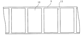
- an electrode for a secondary battery is manufactured. Specifically, as shown in FIG. 3, a positive electrode active material layer 10 is formed on a long strip-shaped positive electrode current collector 9 for manufacturing a plurality of positive electrodes (positive electrode sheets) 2.
- the positive electrode active material layer 10 is intermittently formed on both surfaces of the positive electrode current collector 9.
- the positive electrode active material layer 10 is provided continuously at the thick part 10a which is the main part and at one end of the thick part 10a.
- the thin-walled portion 10b Details of the method of forming the positive electrode active material layer 10 will be described later.
- the end of the coated portion (positive electrode active material layer 10) at the boundary portion 13 with the uncoated portion may be substantially perpendicular to the positive electrode current collector 9, and is inclined as shown in FIG. 2B. It may be. And the boundary part of the thin part 10b and the thick part 10a may also stand substantially perpendicular
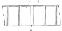
- the boundary portion 13 between the coated portion (portion where the positive electrode active material layer 10 is formed) and the uncoated portion (portion where the positive electrode active material layer 10 is not formed) is covered.
- Insulating member 14 is formed. One end portion 14a of the insulating member 14 is located on the thin portion 2b of the positive electrode active material layer 2, and the other end portion 14b is located on the uncoated portion. If the thickness of the insulating member 14 is small, there is a possibility that sufficient insulation cannot be ensured. Therefore, the thickness is preferably 10 ⁇ m or more.
- the thickness of the insulating member 14 is such that the thickness of the thick portion 10a and the thin portion 10b of the positive electrode active material layer 10 is increased. It is preferably smaller than the difference in thickness.
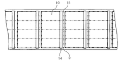
- the positive electrode current collector 9 is cut and divided along a cutting line 15 shown by a two-dot chain line in FIG. 5A, and the desired size shown in FIG. 5B is obtained.
- the positive electrode 2 is obtained.
- the cutting line 15 is a virtual line and is not actually formed.
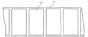
- negative electrode active material layers 12 are intermittently applied to both surfaces of a large-area negative electrode current collector 11 for producing a plurality of negative electrodes (negative electrode sheets) 3.
- the negative electrode active material layer 12 does not have a thin portion and has a certain thickness.
- the end portion of the negative electrode active material layer 12 (end portion of the coating portion) may be slightly inclined or may stand substantially perpendicular to the negative electrode current collector 11.
- the negative electrode current collector 11 is cut and divided along a cutting line 16 shown by a two-dot chain line in FIG. 7A to obtain a desired size shown in FIG. 7B.
- the negative electrode 3 is obtained.
- the cutting line 16 is a virtual line and is not actually formed.
- the positive electrode 2 shown in FIG. 5B and the negative electrode 3 shown in FIG. 7B are alternately stacked via the separator 4 and the positive electrode terminal 7 and the negative electrode terminal 8 are connected. 17 is formed.
- the electrode stack 17 and the electrolytic solution 5 are housed and sealed in an exterior container made of the flexible film 6 to form the secondary battery 1 shown in FIGS. 1A and 1B.
- an increase in thickness due to the insulating member 14 formed so as to cover the boundary portion 13 between the coated portion and the uncoated portion of the positive electrode 2 is greater than the thick portion 10 a of the positive electrode active material layer 10. Is absorbed (cancelled) by the thin thin portion 10b, and a part of the electrode laminate 17 does not become thicker than the other part. Therefore, the electrode laminate 17 can be pressed and held evenly, and deterioration in quality such as variation in electrical characteristics and deterioration in cycle characteristics can be suppressed. If the difference in thickness between the thick part 10a and the thin part 10b is larger than the thickness of the insulating member 14, an increase in the thickness of a part of the electrode laminate 17 by the insulating member 14 can be prevented.
- the uncoated portion of the negative electrode 3 does not exist at the position facing the uncoated portion (positive electrode tab) of the positive electrode 2, and the coated portion is terminated.
- an uncoated portion serving as a negative electrode tab is provided at the end of the negative electrode 3 that does not face the uncoated portion of the positive electrode 2.
- the end positions of the active material layers 10 and 12 may be different or coincide on both surfaces of the current collectors 9 and 11.
- the thickness, distance, and the like of each member of the present invention mean an average value of measured values at any three or more locations unless otherwise specified.
- FIG. 8 is a diagram showing an example of the configuration of a die coater (manufacturing apparatus) that performs intermittent coating in the present invention. As shown in FIG.
- the die coater that performs intermittent application includes a die head 20, a coating valve 21 connected to the die head 20, a pump 22, and a tank 24 that stores a slurry 23 of an active material mixture.
- Relative moving means for moving the current collector 9 relative to the die head 20 is disposed at a position facing the die head 20.
- the current collector is wound up by a winding mechanism (not shown) which is an example of the relative moving means, and the current collector 9 on which the active material layer is to be formed is conveyed along the rotation of the roller 25.
- the die head 20 is driven by a servo motor 26 which is a die head moving means, and can move toward and away from the roller 25, and the displacement (movement amount) of the die head 20 is detected by a movement amount detecting means 27.
- a control means (sequencer) 28 controls the operation of the servo motor 26 based on the detection result of the movement amount detection means 27.
- a return path for returning the slurry from the die head 20 to the tank 24 may be provided, and a return valve may be provided in the return path.
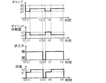
- the coating valve 21 is closed and the slurry is not discharged from the die head 20, and the roller 25 is rotated. Then, the current collector 9 is conveyed. Next, in order to form the thin portion 10b of the active material layer 10, the die head 20 is brought close to the roller 25 and the current collector 9 (displacement x1 of the die head 20, the distance (gap) d1 between the die head 20 and the current collector 9), The coating valve 21 is opened, and the pump 22 is further adjusted to set a predetermined low pressure (discharge pressure p1). Thereby, the slurry 23 is discharged at a low discharge pressure from the die head 20 at a position close to the current collector 9 (illustrated by a two-dot chain line) to form the thin portion 10b.
- the process proceeds to the formation of the thick part 10a. Specifically, after the discharge of the slurry 23 is started, the time t1 required to form the thin portion 10b having a desired size calculated from the conveying speed of the current collector 9, the amount of slurry applied, and the like.
- the sequencer 28 operates the servo motor 26 to move the die head 20 away from the roller 25 and the current collector 9 (displacement x2 of the die head 20, the distance d2 between the die head 20 and the current collector 9).
- the coating valve 21 remains open, and the pump 22 is adjusted to set a predetermined pressure (discharge pressure p2).
- the slurry 23 is discharged at a high discharge pressure from the die head 20 at a position far away from the current collector 9 (shown by a solid line) to form the thick portion 10b. Then, from the time point t1 of the movement of the die head 20 and the adjustment of the pump 22, the time (t2-t1) required to form the thick portion 10a having a desired size calculated from the conveying speed of the current collector 9 is obtained. When the time has elapsed, the coating valve 21 is closed. Thereby, it shifts to formation of an uncoated part. In subsequent times t3 to t5, the formation of the uncoated portion, the formation of the thin portion 10b, and the formation of the thick portion 10a are sequentially repeated to form a large number of active material layers 10.
- the current collector 9 is cut to produce a large number of electrodes 2.
- the time, the amount of slurry applied, the distance between the die head and the current collector foil, and the like are preliminarily set to conditions suitable for forming the thick part 10a, which is the main part of the active material layer 10, and the thin part. Preferably it is set.
- the discharge pressure p1 is set in advance for conditions for forming the thin portion 10b.
- the film thickness and factors affecting the film thickness such as slurry viscosity, are sensed, the slurry coating time, the discharge amount, the die head and the current collector foil Feedback may be applied to the distance adjustment.
- the die head 20 when forming the thin portion 10b, the die head 20 is brought closer to the current collector 9 and the discharge pressure is made smaller than when forming the thick portion 10a.
- the thick part 10a and the thin part 10b can be formed with high accuracy, and for example, a problem that the thin part 10b becomes locally thick at the transition part with the thick part 10a can be suppressed.
- the discharge pressure can be adjusted without a time lag in accordance with the movement of the die head 20, so that the thick portion 10a And the thin part 10b can be formed more accurately.
- the flow rate of the slurry 23 supplied to the die head 20 is adjusted by controlling the pump 22 in accordance with the movement of the die head 20. Specifically, as in the above-described embodiment, when the uncoated portion is formed, the current collector 9 is conveyed by the rotation of the roller 25 without closing the coating valve 21 and discharging the slurry 23 from the die head 20. .
- the die head 20 is brought close to the roller 25 and the current collector 9 (displacement x1 of the die head 20, the distance d1 between the die head 20 and the current collector 9), and the coating valve 21 is opened, and the pump 22 is further adjusted to set a predetermined flow rate q1.
- the slurry 23 is supplied at a small flow rate q1 to the die head 20 at a position close to the current collector 9 (illustrated by a two-dot chain line), and the slurry 23 is discharged from the die head 20 to form the thin portion 10b.
- the sequencer 28 operates the servo motor 26 to move the die head 20 away from the roller 25 and the current collector 9 (displacement x2 of the die head 20). The distance d2) between the die head 20 and the current collector 9). At this time, the coating valve 21 remains open, and the pump 22 is adjusted to set the predetermined flow rate q2. As a result, the slurry 23 is supplied at a large flow rate q2 to the die head 20 at a position far from the current collector 9 (shown by a solid line), and the slurry 23 is discharged from the die head 20 to form the thick portion 10b.
- the coating valve 21 is closed and the process proceeds to formation of an uncoated part.
- the formation of the uncoated portion, the formation of the thin portion 10b, and the formation of the thick portion 10a are repeated in order to form a large number of active material layers 10.
- the current collector 9 is cut to produce a large number of electrodes 2.
- conditions suitable for forming the thick portion 10a are set in advance, that is, the distance d2 between the two when the die head 20 is separated from the current collector 9 and the flow rate q2 at that time are set in advance. Since there are many cases, the distance d1 when the die head 20 is brought closer to the current collector 9 and the flow rate q1 at that time may be newly set as the conditions for forming the thin portion 10b.
- the die head 20 when forming the thin portion 10b, the die head 20 is brought closer to the current collector 9 and the flow rate of the slurry 23 supplied to the die head 20 than when forming the thick portion 10a. Is made smaller. Thereby, the thick part 10a and the thin part 10b can be formed with high accuracy, and for example, a problem that the thin part 10b becomes locally thick at the transition part with the thick part 10a can be suppressed.
- the pump 22 is controlled based on the detection result of the movement amount detection means 27 that detects the movement of the die head 20, the flow rate can be adjusted without a time lag in accordance with the movement of the die head 20, so that the thick portion 10a and The thin portion 10b can be formed with higher accuracy.
- the movement amount detection means described in this specification includes an encoder that detects the movement amount from rotation of a shaft that moves the die head, a displacement sensor that measures the movement of the die head itself, and the like. Not.
- the insulating member 14 is provided only on the positive electrode 2 and the insulating member is not provided on the negative electrode 3, and the positive electrode active material layer 10 includes a thick portion 10 a and a thin portion 10 b.
- the negative electrode active material layer 12 has a configuration having only a thick portion (no thin portion).
- the insulating member is provided only on the negative electrode 3, the insulating member 14 is not provided on the positive electrode 2, the positive electrode active material layer 10 includes only the thick part 10 a, and the negative electrode active material layer 12 includes the thick part and the thin part.
- both the positive electrode active material layer 10 and the negative electrode active material layer 12 may have a thick portion and a thin portion.
- a part of the insulating member is disposed on the thin portion, and the insulating member depends on the thickness difference between the thick portion and the thin portion.
- the present invention is useful for a method of manufacturing a lithium ion secondary battery and its electrode, but is also effective when applied to a method of manufacturing a secondary battery other than a lithium ion battery and its electrode.
Landscapes
- Engineering & Computer Science (AREA)
- Chemical & Material Sciences (AREA)
- Manufacturing & Machinery (AREA)
- Chemical Kinetics & Catalysis (AREA)
- Electrochemistry (AREA)
- General Chemical & Material Sciences (AREA)
- Materials Engineering (AREA)
- Battery Electrode And Active Subsutance (AREA)
- Coating Apparatus (AREA)
Abstract
Description
[二次電池の構成]
図1A,1Bは、本発明の製造方法によって製造される積層型のリチウムイオン二次電池の構成の一例を模式的に示している。図1Aは二次電池の主面(扁平な面)に対して垂直上方から見た平面図であり、図1Bは図1AのA-A線断面図である。図2Aは正極の要部の拡大平面図、図2Bはその拡大断面図である。
本発明のリチウムイオン二次電池1は、正極(正極シート)2と負極(負極シート)3とが、セパレータ4を介して交互に複数層積層された電極積層体(電池素子)17を備えている。この電極積層体17は電解液5と共に、可撓性フィルム6からなる外装容器に収納されている。電極積層体17の正極2には正極端子7の一端が、負極3には負極端子8の一端がそれぞれ接続されている。正極端子7の他端側および負極端子8の他端側は、それぞれ可撓性フィルム6の外部に引き出されている。図1Bでは、電極積層体17を構成する各層の一部(厚さ方向の中間部に位置する層)を図示省略して、電解液5を示している。図1Bでは、見やすくするために、正極2と負極3とセパレータ4とがそれぞれ互いに接触していないように図示しているが、実際にはこれらは密着して積層されている。
本実施形態の負極3は、負極集電体11の両面に、薄肉部を持たない一様な厚さの負極活物質層12が形成されたものであり、絶縁部材14は設けられていない。
二次電池の製造にあたって、まず二次電池用の電極を製造する。具体的には、図3に示すように、複数の正極(正極シート)2を製造するための長尺の帯状の正極集電体9に、正極活物質層10を形成する。この正極活物質層10を正極集電体9の両面にそれぞれ間欠的に形成する。図3,4ではわかりにくいが、図1A~2Bを参照して説明した通り、正極活物質層10は、主要部である厚肉部10aと、厚肉部10aの一端部に連続して設けられている薄肉部10bとからなる。この正極活物質層10の形成方法の詳細については後述する。未塗布部との境界部分13における塗布部(正極活物質層10)の端部は、正極集電体9に対して実質的に垂直に切り立っていてもよく、図2Bに示すように傾斜していてもよい。そして、薄肉部10bと厚肉部10aの境界部分も、正極集電体9に対して実質的に垂直に切り立っていてもよく、傾斜していてもよい。
本発明の各部材の厚さや距離などは、特に断りが無い限りは、任意の3点以上の場所における測定値の平均値を意味する。
前記した本発明の二次電池の製造方法のうち、電極の詳細な作製方法について説明する。以下の説明は、正極2を製造する例に関するものであるが、負極3を以下の方法で製造することも可能である。
本発明において集電体上に活物質層を形成する方法は、主に、ダイヘッドを含むダイコータを用いて、長尺の集電体の長手方向に沿って活物質合剤の塗布部と未塗布部を交互に繰り返して形成する間欠塗布方式である。図8は、本発明において間欠塗布を行うダイコータ(製造装置)の構成の一例を示す図である。図8に示すように、間欠塗布を行うダイコータには、ダイヘッド20と、ダイヘッド20に連結された塗工弁21と、ポンプ22と、活物質合剤のスラリー23を溜めるタンク24が設けられている。ダイヘッド20と対向する位置に、集電体9をダイヘッド20に対して相対移動させる相対移動手段が配置されている。本実施形態では、相対移動手段の一例である図示しない巻き取り機構によって集電体が巻き取られ、ローラ25の回転に沿って、活物質層を形成すべき集電体9が搬送される。ダイヘッド20は、ダイヘッド移動手段であるサーボモータ26に駆動されて、ローラ25に対して近づいたり離れたりすることができ、ダイヘッド20の変位(移動量)は移動量検出手段27によって検知される。制御手段(シーケンサ)28が、移動量検出手段27の検知結果に基づいて、サーボモータ26の動作を制御する。この製造装置は、ダイヘッド20からタンク24にスラリーを戻すリターン経路が設けられていてもよく、リターン経路にはリターン弁が設けられていてもよい。
本発明の他の実施形態における電極の作製方法について、図10を参照して説明する。この実施形態では、ダイヘッド20の移動に合わせてポンプ22を制御して、ダイヘッド20へ供給するスラリー23の流量を調節している。具体的には、前述した実施形態と同様に、未塗布部の形成時には、塗工弁21を閉じてダイヘッド20からスラリー23を吐出することなく、ローラ25の回転によって集電体9を搬送する。次に活物質層10の薄肉部10bを形成するため、ダイヘッド20をローラ25および集電体9に近づける(ダイヘッド20の変位x1、ダイヘッド20と集電体9の間隔d1)とともに、塗工弁21を開き、さらにポンプ22を調節して、所定の流量q1に設定する。それにより、集電体9に対して近接した位置(2点鎖線で図示)のダイヘッド20に、小さい流量q1でスラリー23を供給し、そのスラリー23をダイヘッド20から吐出して薄肉部10bを形成する。
Claims (9)
- 集電体上に活物質層が形成された塗布部を有する二次電池用の電極の製造方法であって、
前記塗布部を形成する工程は、ダイヘッドを前記集電体に近接させた位置で、活物質を含むスラリーを前記ダイヘッドから吐出させて、前記活物質層の厚さが薄い薄肉部を形成する工程と、前記ダイヘッドを、前記薄肉部を形成する工程よりも前記集電体から離れさせた位置で、前記薄肉部を形成する工程よりも大きな吐出圧力で前記スラリーを前記ダイヘッドから吐出させて、前記活物質層の厚さが厚い厚肉部を形成する工程と、を含み、
前記薄肉部を形成する工程と前記厚肉部を形成する工程との移行時には、前記ダイヘッドと前記集電体との間隔の変更に合わせて前記吐出圧力を変更する、二次電池用の電極の製造方法。 - 前記ダイヘッドと前記集電体との間隔の変更は前記ダイヘッドの移動によって行い、前記ダイヘッドの移動を移動量検出手段によって検知し、前記移動量検出手段の検知結果に基づいて、前記ダイヘッドに前記スラリーを供給するポンプを制御して前記吐出圧力を変更する、請求項1に記載の二次電池用の電極の製造方法。
- 集電体上に活物質層が形成された塗布部を有する二次電池用の電極の製造方法であって、
前記塗布部を形成する工程は、ダイヘッドを前記集電体に近接させた位置で、活物質を含むスラリーを前記ダイヘッドから吐出させて、前記活物質層の厚さが薄い薄肉部を形成する工程と、前記ダイヘッドを、前記薄肉部を形成する工程よりも前記集電体から離れさせた位置で、前記薄肉部を形成する工程よりも大きな流量で前記ダイヘッドに供給された前記スラリーを、前記ダイヘッドから吐出させて、前記活物質層の厚さが厚い厚肉部を形成する工程と、を含み、
前記薄肉部を形成する工程と前記厚肉部を形成する工程との移行時には、前記ダイヘッドと前記集電体との間隔の変更に合わせて前記流量を変更する、二次電池用の電極の製造方法。 - 前記ダイヘッドと前記集電体との間隔の変更は前記ダイヘッドの移動によって行い、前記ダイヘッドの移動を移動量検出手段によって検知し、前記移動量検出手段の検知結果に基づいて、前記ダイヘッドに前記スラリーを供給するためのポンプを制御して前記流量を変更する、請求項3に記載の二次電池用の電極の製造方法。
- 前記ダイヘッドから前記集電体に向かって前記スラリーを吐出することなく、前記集電体を、前記ダイヘッドと対向する位置を相対移動させることによって、前記活物質層が形成されていない未塗布部を形成する工程をさらに含み、
前記未塗布部を形成する工程と、前記薄肉部を形成する工程と、前記厚肉部を形成する工程とを、順番に繰り返し実施する、請求項1から4のいずれか1項に記載の二次電池用の電極の製造方法。 - 前記活物質層の前記薄肉部と前記未塗布部とにまたがって絶縁部材を配置する工程をさらに含む、請求項5に記載の二次電池用の電極の製造方法。
- 正極用の集電体の両面に正極用の活物質層を形成して正極を形成する工程と、負極用の集電体の両面に負極用の活物質層を形成して負極を形成する工程と、前記正極と前記負極とをセパレータを介して積層する工程と、を含む二次電池の製造方法であって、
前記正極を形成する工程と前記負極を形成する工程のいずれか一方または両方が、請求項1から6のいずれか1項に記載の二次電池用の電極の製造方法の各工程を含む、二次電池の製造方法。 - 集電体上に活物質層が形成された塗布部を有する二次電池用の電極の製造装置であって、
前記集電体に向かって、活物質を含むスラリーを吐出するダイヘッドと、
前記集電体を、前記ダイヘッドと対向する位置で相対移動させる相対移動手段と、
前記ダイヘッドを、前記相対移動手段によって相対移動させられる前記集電体に対して近づけることと遠ざけることが可能なダイヘッド移動手段と、
前記ダイヘッド移動手段による前記ダイヘッドの変位を検知する移動量検出手段と、
前記ダイヘッドにスラリーを供給するポンプと、
前記ダイヘッドと前記ポンプの間に介在する塗工弁と、
前記移動量検出手段の検知結果に基づいて、前記ダイヘッドが前記集電体に近接した位置にあるときには小さな吐出圧力で前記ダイヘッドから前記スラリーを吐出し、前記ダイヘッドが前記集電体から離れた位置にあるときには大きな吐出圧力で前記ダイヘッドから前記スラリーを吐出するように、前記ポンプを制御する制御手段と、を含む、二次電池用の電極の製造装置。 - 集電体上に活物質層が形成された塗布部を有する二次電池用の電極の製造装置であって、
前記集電体に向かって、活物質を含むスラリーを吐出するダイヘッドと、
前記集電体を、前記ダイヘッドと対向する位置で相対移動させる相対移動手段と、
前記ダイヘッドを、前記相対移動手段によって相対移動させられる前記集電体に対して近づけることと遠ざけることが可能なダイヘッド移動手段と、
前記ダイヘッド移動手段による前記ダイヘッドの変位を検知する移動量検出手段と、
前記ダイヘッドにスラリーを供給するポンプと、
前記ダイヘッドと前記ポンプの間に介在する塗工弁と、
前記移動量検出手段の検知結果に基づいて、前記ダイヘッドが前記集電体に近接した位置にあるときには小さな流量で前記ダイヘッドに前記スラリーを供給し、前記ダイヘッドが前記集電体から離れた位置にあるときには大きな流量で前記ダイヘッドに前記スラリーを供給するように、前記ポンプを制御する制御手段と、を含む、二次電池用の電極の製造装置。
Priority Applications (3)
| Application Number | Priority Date | Filing Date | Title |
|---|---|---|---|
| CN201680028838.9A CN107615523B (zh) | 2015-05-20 | 2016-05-20 | 二次电池电极、二次电池制造方法及制造装置 |
| US15/571,092 US20180175365A1 (en) | 2015-05-20 | 2016-05-20 | Secondary battery electrode, and secondary battery manufacturing method and manufacturing apparatus |
| JP2017519420A JP6739425B2 (ja) | 2015-05-20 | 2016-05-20 | 二次電池用の電極および二次電池の製造方法と製造装置 |
Applications Claiming Priority (2)
| Application Number | Priority Date | Filing Date | Title |
|---|---|---|---|
| JP2015-102506 | 2015-05-20 | ||
| JP2015102506 | 2015-05-20 |
Publications (1)
| Publication Number | Publication Date |
|---|---|
| WO2016186209A1 true WO2016186209A1 (ja) | 2016-11-24 |
Family
ID=57320358
Family Applications (1)
| Application Number | Title | Priority Date | Filing Date |
|---|---|---|---|
| PCT/JP2016/065076 Ceased WO2016186209A1 (ja) | 2015-05-20 | 2016-05-20 | 二次電池用の電極および二次電池の製造方法と製造装置 |
Country Status (4)
| Country | Link |
|---|---|
| US (1) | US20180175365A1 (ja) |
| JP (1) | JP6739425B2 (ja) |
| CN (1) | CN107615523B (ja) |
| WO (1) | WO2016186209A1 (ja) |
Cited By (2)
| Publication number | Priority date | Publication date | Assignee | Title |
|---|---|---|---|---|
| WO2019111616A1 (ja) * | 2017-12-06 | 2019-06-13 | Necエナジーデバイス株式会社 | 集電体電極シート、その製造方法、電池、およびその製造方法 |
| CN110546785A (zh) * | 2017-11-20 | 2019-12-06 | 株式会社Lg化学 | 制造不规则电极的方法 |
Families Citing this family (6)
| Publication number | Priority date | Publication date | Assignee | Title |
|---|---|---|---|---|
| EP3578272B8 (en) * | 2017-02-03 | 2024-12-04 | Vehicle Energy Japan Inc. | Coating die, coating device, coating method, and method for manufacturing secondary cell |
| KR102828489B1 (ko) | 2018-07-09 | 2025-07-03 | 24엠 테크놀로지즈, 인크. | 반-고체 전극 및 배터리 제조의 연속적인 및 반-연속적인 방법들 |
| KR102798490B1 (ko) * | 2019-10-17 | 2025-04-22 | 주식회사 엘지에너지솔루션 | 활물질 이중층을 형성하는 전극 슬러리 코팅 장치 및 방법 |
| JP2020161669A (ja) * | 2019-03-27 | 2020-10-01 | 太陽誘電株式会社 | 電気化学デバイス |
| WO2022076946A1 (en) * | 2020-10-09 | 2022-04-14 | 24M Technologies, Inc. | Methods of continuous and semi-continuous production of electrochemical cells |
| CN114226164A (zh) * | 2021-12-18 | 2022-03-25 | 惠州市信宇人科技有限公司 | 电极材料的涂布方法、精密程控式涂布供料的呑吐阀及其涂布头 |
Citations (4)
| Publication number | Priority date | Publication date | Assignee | Title |
|---|---|---|---|---|
| JP2010232073A (ja) * | 2009-03-27 | 2010-10-14 | Sanyo Electric Co Ltd | 非水電解質二次電池用の電極の製造方法 |
| JP2013188663A (ja) * | 2012-03-13 | 2013-09-26 | Toppan Printing Co Ltd | 間欠塗布装置 |
| JP2014211946A (ja) * | 2011-08-30 | 2014-11-13 | パナソニック株式会社 | 非水系二次電池用電極板およびこれを用いた非水系二次電池 |
| JP2015013248A (ja) * | 2013-07-04 | 2015-01-22 | 株式会社豊田自動織機 | 塗工装置及び電極の製造方法 |
Family Cites Families (9)
| Publication number | Priority date | Publication date | Assignee | Title |
|---|---|---|---|---|
| JP4411690B2 (ja) * | 1999-06-30 | 2010-02-10 | パナソニック株式会社 | リチウムイオン二次電池 |
| JP2005046694A (ja) * | 2003-07-31 | 2005-02-24 | Toshiba Corp | 塗布膜形成方法及び塗布装置 |
| JP4575103B2 (ja) * | 2004-09-30 | 2010-11-04 | 大日本印刷株式会社 | 電極板の製造方法および製造装置 |
| US8147565B2 (en) * | 2009-01-15 | 2012-04-03 | Panasonic Corporation | Method for manufacturing electrode plate for battery |
| JP5858325B2 (ja) * | 2010-09-03 | 2016-02-10 | 株式会社Gsユアサ | 電池 |
| US8771793B2 (en) * | 2011-04-15 | 2014-07-08 | Roche Diagnostics Operations, Inc. | Vacuum assisted slot die coating techniques |
| US20130236771A1 (en) * | 2012-03-08 | 2013-09-12 | Robert Bosch Gmbh | Rechargeable battery and method of manufacturing the same |
| DE102012224228A1 (de) * | 2012-12-21 | 2014-06-26 | Robert Bosch Gmbh | Verfahren und Vorrichtung zur Nassbeschichtung eines Substrats |
| JP6267141B2 (ja) * | 2014-06-04 | 2018-01-24 | 東京エレクトロン株式会社 | 液塗布方法、液塗布装置、及びコンピュータ読み取り可能な記録媒体 |
-
2016
- 2016-05-20 US US15/571,092 patent/US20180175365A1/en not_active Abandoned
- 2016-05-20 JP JP2017519420A patent/JP6739425B2/ja active Active
- 2016-05-20 CN CN201680028838.9A patent/CN107615523B/zh active Active
- 2016-05-20 WO PCT/JP2016/065076 patent/WO2016186209A1/ja not_active Ceased
Patent Citations (4)
| Publication number | Priority date | Publication date | Assignee | Title |
|---|---|---|---|---|
| JP2010232073A (ja) * | 2009-03-27 | 2010-10-14 | Sanyo Electric Co Ltd | 非水電解質二次電池用の電極の製造方法 |
| JP2014211946A (ja) * | 2011-08-30 | 2014-11-13 | パナソニック株式会社 | 非水系二次電池用電極板およびこれを用いた非水系二次電池 |
| JP2013188663A (ja) * | 2012-03-13 | 2013-09-26 | Toppan Printing Co Ltd | 間欠塗布装置 |
| JP2015013248A (ja) * | 2013-07-04 | 2015-01-22 | 株式会社豊田自動織機 | 塗工装置及び電極の製造方法 |
Cited By (3)
| Publication number | Priority date | Publication date | Assignee | Title |
|---|---|---|---|---|
| CN110546785A (zh) * | 2017-11-20 | 2019-12-06 | 株式会社Lg化学 | 制造不规则电极的方法 |
| WO2019111616A1 (ja) * | 2017-12-06 | 2019-06-13 | Necエナジーデバイス株式会社 | 集電体電極シート、その製造方法、電池、およびその製造方法 |
| JPWO2019111616A1 (ja) * | 2017-12-06 | 2020-11-19 | 株式会社エンビジョンAescエナジーデバイス | 集電体電極シート、その製造方法、電池、およびその製造方法 |
Also Published As
| Publication number | Publication date |
|---|---|
| JPWO2016186209A1 (ja) | 2018-03-08 |
| CN107615523A (zh) | 2018-01-19 |
| CN107615523B (zh) | 2020-11-20 |
| US20180175365A1 (en) | 2018-06-21 |
| JP6739425B2 (ja) | 2020-08-12 |
Similar Documents
| Publication | Publication Date | Title |
|---|---|---|
| JP6418650B2 (ja) | 積層型二次電池および電極の製造方法 | |
| JP6739425B2 (ja) | 二次電池用の電極および二次電池の製造方法と製造装置 | |
| CN105794022B (zh) | 二次电池及其制造方法 | |
| JP6381045B2 (ja) | 二次電池 | |
| JP6621765B2 (ja) | 二次電池 | |
| JP6292678B2 (ja) | 二次電池と電極の製造方法 | |
| JP6609564B2 (ja) | 二次電池用電極の製造方法および製造装置 | |
| JP7002094B2 (ja) | 電気化学デバイス用の電極と、電気化学デバイスと、それらの製造方法 | |
| JP6628505B2 (ja) | 二次電池用の電極の製造方法および製造装置と二次電池の製造方法 | |
| WO2017154312A1 (ja) | 電気化学デバイス用電極と電気化学デバイスの製造方法 | |
| JPWO2017154313A1 (ja) | 電気化学デバイス用電極および電気化学デバイスとそれらの製造方法 | |
| JP2010086717A (ja) | リチウム二次電池用電極及びリチウム二次電池 | |
| JP2018045952A (ja) | 電極及び電気化学デバイスの製造方法と電極ロール | |
| JP6632793B2 (ja) | 二次電池用電極の製造方法および製造装置 | |
| JPWO2018051850A1 (ja) | 電池用電極の製造方法及び電池用電極の製造装置及び電池用電極及び電池 |
Legal Events
| Date | Code | Title | Description |
|---|---|---|---|
| 121 | Ep: the epo has been informed by wipo that ep was designated in this application |
Ref document number: 16796602 Country of ref document: EP Kind code of ref document: A1 |
|
| WWE | Wipo information: entry into national phase |
Ref document number: 15571092 Country of ref document: US |
|
| ENP | Entry into the national phase |
Ref document number: 2017519420 Country of ref document: JP Kind code of ref document: A |
|
| NENP | Non-entry into the national phase |
Ref country code: DE |
|
| 122 | Ep: pct application non-entry in european phase |
Ref document number: 16796602 Country of ref document: EP Kind code of ref document: A1 |