WO2016186113A1 - 切削インサート、工具ボデーおよび切削工具 - Google Patents
切削インサート、工具ボデーおよび切削工具 Download PDFInfo
- Publication number
- WO2016186113A1 WO2016186113A1 PCT/JP2016/064621 JP2016064621W WO2016186113A1 WO 2016186113 A1 WO2016186113 A1 WO 2016186113A1 JP 2016064621 W JP2016064621 W JP 2016064621W WO 2016186113 A1 WO2016186113 A1 WO 2016186113A1
- Authority
- WO
- WIPO (PCT)
- Prior art keywords
- cutting
- cutting insert
- angle
- face
- tool body
- Prior art date
Links
Images


Classifications
-
- B—PERFORMING OPERATIONS; TRANSPORTING
- B23—MACHINE TOOLS; METAL-WORKING NOT OTHERWISE PROVIDED FOR
- B23B—TURNING; BORING
- B23B27/00—Tools for turning or boring machines; Tools of a similar kind in general; Accessories therefor
- B23B27/04—Cutting-off tools
-
- B—PERFORMING OPERATIONS; TRANSPORTING
- B23—MACHINE TOOLS; METAL-WORKING NOT OTHERWISE PROVIDED FOR
- B23B—TURNING; BORING
- B23B27/00—Tools for turning or boring machines; Tools of a similar kind in general; Accessories therefor
- B23B27/14—Cutting tools of which the bits or tips or cutting inserts are of special material
- B23B27/141—Specially shaped plate-like cutting inserts, i.e. length greater or equal to width, width greater than or equal to thickness
- B23B27/145—Specially shaped plate-like cutting inserts, i.e. length greater or equal to width, width greater than or equal to thickness characterised by having a special shape
-
- B—PERFORMING OPERATIONS; TRANSPORTING
- B23—MACHINE TOOLS; METAL-WORKING NOT OTHERWISE PROVIDED FOR
- B23B—TURNING; BORING
- B23B27/00—Tools for turning or boring machines; Tools of a similar kind in general; Accessories therefor
- B23B27/14—Cutting tools of which the bits or tips or cutting inserts are of special material
- B23B27/16—Cutting tools of which the bits or tips or cutting inserts are of special material with exchangeable cutting bits or cutting inserts, e.g. able to be clamped
- B23B27/1614—Cutting tools of which the bits or tips or cutting inserts are of special material with exchangeable cutting bits or cutting inserts, e.g. able to be clamped with plate-like cutting inserts of special shape clamped against the walls of the recess in the shank by a clamping member acting upon the wall of a hole in the insert
- B23B27/1622—Cutting tools of which the bits or tips or cutting inserts are of special material with exchangeable cutting bits or cutting inserts, e.g. able to be clamped with plate-like cutting inserts of special shape clamped against the walls of the recess in the shank by a clamping member acting upon the wall of a hole in the insert characterised by having a special shape
-
- B—PERFORMING OPERATIONS; TRANSPORTING
- B23—MACHINE TOOLS; METAL-WORKING NOT OTHERWISE PROVIDED FOR
- B23B—TURNING; BORING
- B23B2200/00—Details of cutting inserts
- B23B2200/04—Overall shape
- B23B2200/0423—Irregular
-
- B—PERFORMING OPERATIONS; TRANSPORTING
- B23—MACHINE TOOLS; METAL-WORKING NOT OTHERWISE PROVIDED FOR
- B23B—TURNING; BORING
- B23B2200/00—Details of cutting inserts
- B23B2200/08—Rake or top surfaces
- B23B2200/082—Rake or top surfaces with elevated clamping surface
-
- B—PERFORMING OPERATIONS; TRANSPORTING
- B23—MACHINE TOOLS; METAL-WORKING NOT OTHERWISE PROVIDED FOR
- B23B—TURNING; BORING
- B23B2200/00—Details of cutting inserts
- B23B2200/28—Angles
Definitions
- the present invention relates to a cutting insert that is detachably attached to a cutting tool, a tool body to which the cutting insert is attached, and a cutting tool.
- the cutting insert is a cutting insert having two end surfaces (upper surface 2 and lower surface 3) and a peripheral side surface (side surface 4) connecting between the end surfaces, and the peripheral side surface is a straight front cutting edge.
- (Cutting edge 5), rake face, and front flank face 9 are included.
- the front cutting edge and one end surface (lower surface 3) form an acute angle.
- the front cutting edge and the intersecting ridge line between one end face (lower face 3) and the peripheral side face are reduced by an angle ⁇ from 90 ° to form an acute angle.
- a tool body and a cutting tool to which the cutting insert is attached are suitable for grooving or parting off.
- chips are sandwiched between the end face of the cutting insert and the workpiece when, for example, grooving is performed at the corner of the workpiece, the workpiece is processed.
- Objects or cutting inserts may be damaged. That is, as viewed from the direction facing the rake face, the angle formed by the front cutting edge and the intersecting ridge line between the lower surface and the peripheral side surface is only slightly smaller than 90 ° (the angle ⁇ is about 1 ° to 2 °). There is a problem that the gap between the lower surface and the work piece is small and chips are easily caught.
- the cutting insert of this invention is a cutting insert which has a 1st end surface, the 2nd end surface facing the 1st end surface, and the surrounding side surface which connects between the 1st and 2nd end surface, Comprising: Includes a rake face, a front flank face, and a first cutting edge located at an intersection ridge line portion of the rake face and the front flank face.
- the first end surface includes a central surface and a side flank located on the front flank side with respect to the central surface. When viewed from the direction facing the rake face, the intersection ridge line portion between the central surface and the peripheral side surface is the first ridge line, and the intersection ridge line portion between the side flank and the peripheral side surface is the second ridge line, and faces the rake surface.
- the angle formed between the first cutting edge and the first ridge line is defined as a first angle ⁇
- the angle formed between the first cutting edge and the second ridge line is defined as a second angle ⁇ .
- the angle ⁇ of 1 is smaller than the second angle ⁇ .
- the tool body of the present invention is a tool body of a cutting tool for detachably mounting the cutting insert of the present invention, and includes a bottom surface of a tip seat that contacts the second end surface of the cutting insert.
- the cutting tool of the present invention is a cutting tool provided with the cutting insert of the present invention.
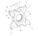
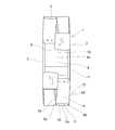
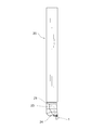
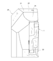
- FIG. 1 It is a perspective view of the cutting insert in one embodiment of the present invention. It is a right view of the cutting insert shown in FIG. It is a front view of the cutting insert shown in FIG. It is a top view of the cutting insert shown in FIG. It is a bottom view of the cutting insert shown in FIG. It is the schematic diagram which looked at the cutting insert shown in FIG. 1 from the direction facing a rake face. It is a perspective view of the cutting tool in one embodiment of the present invention. It is a top view of the cutting tool shown in FIG. It is the elements on larger scale of FIG. It is a right view of the cutting tool shown in FIG. It is a front view of the cutting tool shown in FIG. It is an expansion perspective view of the state which removed the cutting insert from the cutting tool shown in FIG.
- the cutting insert 1 in this embodiment has two opposing end surfaces 2 and 3 and a peripheral side surface 4.
- the peripheral side surface 4 connects between the two end surfaces 2 and 3.
- a through hole is provided in the approximate center of the two end faces 2 and 3.
- the contour shape of the two end faces 2 and 3 has four corners.
- the peripheral side surface 4 includes four cutting edges 5 at positions corresponding to the four corners.
- the cutting edge 5 is formed at the intersection ridge line portion between the rake face 6 and the flank face.
- the rake face 6 is formed on the peripheral side face 4.
- Each of the four cutting edges has a shape rotationally symmetric with respect to each other by 180 °.
- the cutting insert 1 has a 180 ° rotationally symmetric shape as viewed from the direction facing each of the two end faces 2 and 3. Further, the cutting insert 1 has a 180 ° rotationally symmetric shape with respect to a direction in which the two end faces 2 and 3 are reversed so as to be interchanged. Therefore, even if one cutting edge 5 is damaged and cannot be used, the cutting insert 1 can be used at least four times by replacing the direction with the other three cutting edges 5 and is economical. Since the shape and function of the four cutting edges 5 are the same, only one cutting edge 5 will be described below, and description of the other three cutting edges 5 will be omitted. In FIG.
- the distance in the left-right direction of each corner where each cutting edge 5 is formed is about 18 mm.
- the distance in the vertical direction of each corner is about 20 mm.
- the thickness which is the dimension between the two end faces 2 and 3 is about 4 mm.
- terms indicating the position and direction in space such as up, down, left, and right may be used, but these terms do not limit the present invention, and the present invention is limited based on these terms. Not intended to be interpreted.
- the peripheral side surface 4 further includes a front clearance surface 7a.
- the cutting edge 5 formed in the intersection ridgeline part of the front flank 7a and the rake face 6 is referred to as a first cutting edge 5a.
- the cutting edge 5 includes a first corner cutting edge 5b connected to one end of the first cutting edge 5a and a second corner cutting edge 5c connected to the other end. Further, the cutting edge 5 includes a first side cutting edge 5d connected to the first corner cutting edge 5b and a second side cutting edge 5e connected to the second corner cutting edge 5c.
- the cutting edge 5 is composed of a first side cutting edge 5d, a first corner cutting edge 5b, a first cutting edge 5a, a second corner cutting edge 5c, and a second side cutting edge 5e in this order.
- One of the two end faces is a first end face 2 and the other end face is a third end face 3.
- the end face on the first side cutting edge 5d side is referred to as a first end face 2.
- the third end surface 3 has a seating surface that comes into contact with the tip seat 22 of the tool body 21.
- the second end surface 2 includes a central surface 2a.
- the central surface 2a acts as a seating surface when the cutting insert 1 is used with the first end surface 2 and the second end surface 3 reversed.
- the second end surface 2 includes a side flank 7b formed on the front flank 7a side with respect to the central surface 2a.
- the first side cutting edge 5d is formed at the intersecting ridge line portion between the side flank 7b and the rake face 6.
- the flank corresponding to the first corner cutting edge 5b can be referred to as a corner flank 7c.
- the side flank 7b is adjacent to the front flank 7a across the corner flank 7c. That is, the side flank 7b is connected to the front flank 7a via the corner flank 7c. Further, the side flank 7b is connected to the central surface 2a via a connection surface.
- the connection surface of the cutting insert 1 in this embodiment is formed in the step shape, it is not limited to this.
- the connecting surface may have any shape as long as the side flank 7b and the central surface 2a can be connected. Further, the connection surface may not be formed, and the side relief surface 7b and the center surface 2a may be directly connected.
- the rake face 6 is curved in a concave shape so that a chip breaker is formed. A positive rake angle is imparted by the chip breaker, and cutting resistance can be reduced.
- the shape of the chip breaker is not limited to the shape of this embodiment, and various known shapes can be applied.
- the cutting insert 1 in this embodiment is suitable for grooving or parting off.
- the intersecting ridge line portion between the central surface 2 a and the peripheral side surface 4 is defined as the first ridge line 11, the side flank 7 b and the rake face 6 Is defined as a second ridgeline 12.
- the angle formed between the first cutting edge 5 a and the first ridge line 11 when viewed from the direction facing the rake face 6 is defined as the first angle ⁇ , and the first cutting edge is formed.
- An angle formed by the blade 5a and the second ridge line 12 is defined as a second angle ⁇ .
- the first angle ⁇ is made smaller than the second angle ⁇ .
- the second ridge line 12 coincides with the first side cutting edge 5d.
- the first angle ⁇ is made smaller than the second angle ⁇
- the first side cutting edge 5d and the first ridge line 11 of the central portion 2a are viewed from the direction facing the rake face 6. It arrange
- the direction facing the rake face 6 means a direction facing the peripheral side face 4 including the rake face 6, that is, The plan view shown in FIG. 4 is meant.
- the material around the cutting edge 5 of the cutting insert 1 is a hard material such as cemented carbide, cermet, ceramic, diamond, sintered body containing cubic boron nitride, or a PVD or CVD coating film on the surface of these hard materials. It may be selected from those coated.
- the material of the cutting insert 1 other than the cutting edge 5 is preferably a similar hard material.
- the second end surface 3 abuts against the bottom surface 22 a of the tip seat 22, and the peripheral side surface 4 has two tip seats. It contacts the wall surface portions 22b1 and 22b2.
- the bottom surface 22 a of the chip seat 22 is the surface that contacts the cutting insert 1 most widely.
- the wall surface portions 22b1 and 22b2 of the chip seat 22 are surfaces that rise like a wall with respect to the bottom surface 22a.
- the peripheral side surface 4 of the cutting insert 1 includes first and second holding portions 8 a and 8 b that are holding portions that come into contact with the wall surface portions 22 b 1 and 22 b 2 of the chip seat 22.
- the holding portion 8 positioned on the lower side is referred to as a first holding portion 8a
- the holding portion 8 formed on the upper side is referred to as a second holding portion 8b. Therefore, of the cutting resistance applied to the first cutting edge 5a that is the working cutting edge, the holding portion 8 that mainly receives the main component force becomes the first holding portion 8a.
- the main component force of the cutting force mainly acts from the upper side to the lower side with respect to the working cutting edge. Therefore, the first holding portion 8a formed on the lower side mainly uses the main component force of the cutting force.
- the cutting insert 1 is fixed to the tip seat 22 of the tool body 21 by causing the second holding portion 8b to cooperate with the first holding portion 8a.
- the first holding portion 8 a has at least two contact surfaces 10 that are spaced apart from each other in the circumferential direction of the cutting insert 1.
- the two contact surfaces 10 are each formed as a part of the recess 9 and are disposed so as to face each other.
- the second holding portion 8 b has at least one abutting surface 10.
- the contact surface 10 of the second holding portion 8 b is also formed as a part of the recess 9.
- the cutting insert 1 in this embodiment is formed to be 180 ° rotationally symmetric, and the contact surface 10 of the second holding portion 8b is 180 ° with the contact surface 10 of the first holding portion 8a. ° It has a rotationally symmetric shape and arrangement. That is, four contact surfaces 10 are formed, and three of them are in contact with the two wall surface portions 22 b 1 and 22 b 2 of the chip seat 22.
- the cutting tool 20 in this embodiment is a lathe tool. More specifically, it is a small tool for a small lathe, also called an automatic lathe, that is, a small turning tool. As described above, since the cutting insert 1 in this embodiment is suitable for grooving and parting, the cutting tool 20 is suitable for grooving and parting.
- the tool body 21 of the cutting tool 20 in this embodiment is a square whose cross-sectional shape of the shank is 12 mm on each side. In order to enable highly efficient cutting, a small lathe is mounted so that a large number of cutting tools are concentrated on a comb-type tool post or the like.
- the cutting tool used is a small cutting tool having a cross-sectional shape of the shank of about 10 mm to 16 mm on each side.
- the present invention can be applied to cutting tools for various uses such as for threading. Further, the present invention is not limited to a small lathe, and can be applied to a cutting tool having a shank cross-sectional shape of 20 mm or more on each side.
- the clamping member 30 of the cutting tool 20 in this embodiment is a fastening screw 30.
- the tightening screw 30 passes through the through hole of the cutting insert 1 and is screwed into a screw hole formed in the chip seat 22.
- the clamp member 30 is not limited to this embodiment.
- Various known mounting methods of the cutting insert 1 such as a clamping method using a lever can be applied.
- the wall surface of the chip seat 22 includes two wall surface portions 22b1 and 22b2. That is, it includes a first wall surface portion 22b1 that contacts the first holding portion 8a of the cutting insert 1 and a second wall surface portion 22b2 that contacts the second holding portion 8b.
- the wall surface shown on the right side in FIG. 12 between the first wall surface portion 22 b 1 and the second wall surface portion 22 b 2 is formed so as not to contact the cutting insert 1.
- the open part shown on the left side in FIG. 12 is formed in a part of the wall surface.
- the first and second wall surface portions 22b1 and 22b2 are shaped to abut against the first and second holding portions 8a and 8b, respectively. That is, the first wall surface portion 22b1 of the cutting tool 20 in this embodiment has a convex curved surface portion.
- the second wall surface portion 22b2 also has a convex curved surface portion.
- the present invention is not limited to these, and the first and second wall surface portions 22b1 and 22b2 of the tip seat 22 can contact the first and second holding portions 8a and 8b of the cutting insert 1 to fix the cutting insert 1. Any shape can be used as long as it has a shape.
- the first and second wall surface portions 22b1 and 22b2 of the chip seat 22 have at least two first wall surface portions 22b1 on the lower side so that the cutting insert 1 does not move even when receiving cutting force applied to the working cutting edge. It is good to contact
- the cutting insert 1 and the wall surface of the chip seat 22 come into contact with each other at three positions where they are arranged at positions away from each other and the direction of the contact surface 10 is different, the cutting insert 1 is firmly attached to the chip seat 22. It is securely fixed to.
- a chip pocket 24 is formed on the tip side and the upper side of the tool body 21.
- the chip pocket is a space for smoothly discharging chips generated during grooving or parting off the groove to be processed.
- the first angle ⁇ is set to be smaller than the second angle ⁇ .
- the center surface 2a When the center surface 2a is formed in this way, it can also be referred to as a front cutting edge when viewed from the direction facing the rake face 6 when grooving a corner of a workpiece such as a flange portion.
- the width of the machining groove defined by the first cutting edge 5a, the first corner cutting edge 5b, and the second corner cutting edge 5c first escaped by the second angle ⁇ and then the first angle
- the central surface 2a is largely escaped from the groove processing surface, flange portion, and the like.
- the gap between the workpiece and the central surface 2a can be increased by changing the angle. For this reason, it becomes difficult for a chip etc. to pinch
- the first angle ⁇ is preferably formed in a range of 75 ° or more and 87 ° or less.
- the angle difference between the first angle ⁇ and the second angle ⁇ is preferably formed in a range of 1 ° or more and 10 ° or less.
- the second angle ⁇ is preferably formed in the range of 85 ° or more and 89 ° or less.
- the second angle ⁇ is preferably formed in the range of 85 ° or more and 89 ° or less.
- the second angle ⁇ exceeds 89 ° and approaches 90 °, the gap between the side flank 7b and the workpiece is reduced, and chips are easily caught. If the first angle ⁇ is less than 75 °, the strength of the cutting insert 1 may be insufficient as in the case of the second angle ⁇ . When the first angle ⁇ exceeds 87 °, the gap between the central surface 2a and the workpiece becomes small, and chips are easily caught.
- the chip pocket 24 is preferably formed as a concave curved surface that is recessed inward.
- the chip pocket 24 is formed so as to reduce obstacles protruding upward with respect to the first cutting edge 5a which is a working cutting edge. If there is no upper convex part 23, even if there is no chip pocket 24, chip discharge is performed smoothly.
- the cutting insert 1 and the cutting tool 20 in this embodiment require the second wall surface portion 22b2 that comes into contact with the second holding portion 8b. is necessary. For this reason, a chip pocket 24 is formed for discharging chips.
- the radius of curvature R of the concave curved chip pocket 24 is more preferably in the range of 2 mm or more and 20 mm or less in a side view (right side view) shown in FIG.
- the top portion of the upper convex portion 23 on the tip side is formed such that the width gradually decreases toward the tip.
- the upper convex portion 23 is formed in such a shape, a synergistic effect with the chip pocket 24 is generated, and the chip discharging property is further improved.
- the contour shape of the apex portion on the tip side of the upper convex portion 23 is streamlined.
- the present invention is not limited to this, and any shape may be used as long as it does not disturb chip discharge.
- the cutting insert 1 of the present invention can be manufactured by powder pressure molding and sintering. Further, grinding can be performed after sintering to obtain a cutting insert with high dimensional accuracy.
- the tool body 21 of the present invention can be manufactured by cutting.
- the cutting insert and the cutting tool of the present invention are not limited to the embodiment described above, and various changes and additions can be made without departing from the gist of the present invention.
- the present invention is not limited to a lathe cutting tool, and can be applied to a rotary cutting tool.
Abstract
Description
2 第1の端面
2a 中央面
3 第2の端面
4 周側面
5 切れ刃
5a 第1の切れ刃
5b 第1のコーナ切れ刃
5c 第2のコーナ切れ刃
5d 第1の側部切れ刃
5e 第2の側部切れ刃
6 すくい面
7a 前部逃げ面
7b 側部逃げ面
7c コーナ逃げ面
8a 第1の保持部分
8b 第2の保持部分
9 凹部
10 当接面
11 第1の稜線
12 第2の稜線
20 切削工具
21 工具ボデー
22 チップ座
22a チップ座の底面
22b1、22b2 チップ座の第1および第2の壁面部分
23 上方凸部
24 切りくずポケット
30 締め付けねじ
R 切りくずポケットの曲率半径
α 第1の角度
β 第2の角度
Claims (14)
- 第1の端面(2)と、該第1の端面(2)と対向する第2の端面(3)と、該第1および第2の端面(2、3)の間をつなぐ周側面(4)とを有する切削インサート(1)であって、
前記周側面(4)は、すくい面(6)と、前部逃げ面(7a)と、該すくい面(6)と該前部逃げ面(7a)との交差稜線部に位置する第1の切れ刃(5a)とを含み、
前記第1の端面(2)は、中央面(2a)と、該中央面(2a)よりも前記前部逃げ面(7a)側に位置する側部逃げ面(7b)とを含み、
前記すくい面(6)に対向する方向からみて、前記中央面(2a)と前記周側面(4)との交差稜線部を第1の稜線(11)とし、前記側部逃げ面(7b)と前記周側面(4)との交差稜線部を第2の稜線(12)とし、
前記すくい面(6)に対向する方向からみて、前記第1の切れ刃(5a)と前記第1の稜線(11)とのなす角を第1の角度(α)とし、前記第1の切れ刃(5a)と前記第2の稜線(12)とのなす角を第2の角度(β)とすると、
前記第1の角度(α)は前記第2の角度(β)よりも小さい切削インサート(1)。 - 前記第2の角度(β)は、85°以上、かつ89°以下の範囲とされる請求項1に記載の切削インサート(1)。
- 前記第1の角度(α)は、75°以上、かつ87°以下の範囲とされる請求項1または2に記載の切削インサート(1)。
- 前記第1の角度(α)と第2の角度(β)との角度差は、1°以上、かつ10°以下の範囲とされる請求項1から3のいずれか一項に記載の切削インサート(1)。
- 前記第1の切れ刃(5a)の両側に、各々のコーナ切れ刃(5b、5c)を介して、側部切れ刃(5d、5e)を有する請求項1から4のいずれか一項に記載の切削インサート(1)。
- 突っ切り加工または溝入れ加工に用いられる請求項1から5のいずれか一項に記載の切削インサート(1)。
- 前記周側面(4)は、少なくとも2つの保持部分(8a、8b)を備え、
前記保持部分(8a、8b)は、それぞれ当接面(10)を有する凹部(9)を有する請求項1から6のいずれか一項に記載の切削インサート(1)。 - 請求項1から7のいずれか一項に記載の切削インサート(1)を着脱自在に装着するための切削工具(20)の工具ボデー(21)であって、
前記切削インサート(1)の前記第2の端面(3)と当接するチップ座(22)の底面(22a)を備える工具ボデー(21)。 - 前記切削インサート(1)の前記周側面(4)は、少なくとも2つの保持部分(8a、8b)を備え、
前記2つの保持部分(8a、8b)は、それぞれ当接面(10)を有する凹部(9)を有し、
該工具ボデー(21)のチップ座(22)は、前記当接面(10)に当接する少なくとも2つの壁面部分(22b1、22b2)を備える請求項8に記載の工具ボデー(21)。 - 前記切削インサート(1)の前記保持部分(8a、8b)のうち、第1の保持部分(8a)は、前記第1の切れ刃(5a)からみて、前記すくい面(6)側に配置され、
前記第1の保持部分(8a)と当接する第1の壁面部分(22b1)は、該工具ボデー(21)の先端側、かつ上方に位置し、
前記第1の壁面部分(22b1)を含む上方凸部(23)を有し、
前記上方凸部(23)は、少なくとも1つの切りくずポケット(24)を備える請求項9に記載の工具ボデー(21)。 - 前記切りくずポケット(24)は、内方に向かって凹む凹曲面として形成される請求項10に記載の工具ボデー(21)。
- 側面視において、凹曲面状の前記切りくずポケット(24)の曲率半径(R)は、2mm以上、かつ20mm以下の範囲とされる請求項11に記載の工具ボデー(21)。
- 平面視において、上方凸部(23)の先端側の頂部は、先端に向かうにつれ幅が漸次小さくなる請求項10に記載の工具ボデー(21)。
- 請求項1から7のいずれかに記載の切削インサート(1)を備える切削工具。
Priority Applications (4)
| Application Number | Priority Date | Filing Date | Title |
|---|---|---|---|
| CN201680026792.7A CN107614166B (zh) | 2015-05-20 | 2016-05-17 | 切削刀片、刀具体以及切削刀具 |
| EP16796506.0A EP3241638B1 (en) | 2015-05-20 | 2016-05-17 | Cutting insert, tool body, and cutting tool |
| JP2016554517A JP6048715B1 (ja) | 2015-05-20 | 2016-05-17 | 切削インサート、工具ボデーおよび切削工具 |
| US15/541,606 US10201855B2 (en) | 2015-05-20 | 2016-05-17 | Cutting insert, tool body and cutting tool |
Applications Claiming Priority (2)
| Application Number | Priority Date | Filing Date | Title |
|---|---|---|---|
| JP2015103244 | 2015-05-20 | ||
| JP2015-103244 | 2015-05-20 |
Publications (1)
| Publication Number | Publication Date |
|---|---|
| WO2016186113A1 true WO2016186113A1 (ja) | 2016-11-24 |
Family
ID=57320139
Family Applications (1)
| Application Number | Title | Priority Date | Filing Date |
|---|---|---|---|
| PCT/JP2016/064621 WO2016186113A1 (ja) | 2015-05-20 | 2016-05-17 | 切削インサート、工具ボデーおよび切削工具 |
Country Status (5)
| Country | Link |
|---|---|
| US (1) | US10201855B2 (ja) |
| EP (1) | EP3241638B1 (ja) |
| JP (1) | JP6048715B1 (ja) |
| CN (1) | CN107614166B (ja) |
| WO (1) | WO2016186113A1 (ja) |
Cited By (5)
| Publication number | Priority date | Publication date | Assignee | Title |
|---|---|---|---|---|
| JP2019005888A (ja) * | 2017-06-23 | 2019-01-17 | 株式会社タンガロイ | 切削工具 |
| CN109570629A (zh) * | 2017-09-28 | 2019-04-05 | 株式会社泰珂洛 | 切削工具 |
| JP6937987B1 (ja) * | 2021-03-23 | 2021-09-22 | イスカル リミテッド | 切削インサート |
| JP7003389B1 (ja) * | 2021-04-28 | 2022-01-20 | 株式会社タンガロイ | 切削インサート及び切削工具 |
| US11759865B2 (en) | 2021-01-13 | 2023-09-19 | Tungaloy Corporation | Tool body |
Families Citing this family (4)
| Publication number | Priority date | Publication date | Assignee | Title |
|---|---|---|---|---|
| JP6921230B2 (ja) * | 2017-11-28 | 2021-08-18 | 京セラ株式会社 | 切削工具及び切削加工物の製造方法 |
| TWI718014B (zh) * | 2020-02-26 | 2021-02-01 | 昇益興企業有限公司 | 車刀及包括該車刀之車刀結構 |
| JP7004189B1 (ja) * | 2021-04-15 | 2022-01-21 | 株式会社タンガロイ | 切削インサート及び切削工具 |
| CN113996826A (zh) * | 2021-12-07 | 2022-02-01 | 国宏工具系统(无锡)股份有限公司 | 一种加工不锈钢产品的轮廓成型刀片 |
Citations (6)
| Publication number | Priority date | Publication date | Assignee | Title |
|---|---|---|---|---|
| JPS52109280U (ja) * | 1976-02-17 | 1977-08-19 | ||
| JPS6229204U (ja) * | 1985-08-06 | 1987-02-21 | ||
| JPS6281504U (ja) * | 1985-11-07 | 1987-05-25 | ||
| DE102006017458A1 (de) * | 2006-03-08 | 2007-09-13 | Kemmer Hartmetallwerkzeuge Gmbh | Schneidplatte mit vier Schneiden und Trägerwerkzeug für Schneidplatten mit vier Schneiden |
| US20090162154A1 (en) * | 2007-12-20 | 2009-06-25 | Seco Tools Ab | Indexable turning insert and a cutting tool comprising such an insert |
| JP2015044242A (ja) * | 2013-08-27 | 2015-03-12 | 京セラ株式会社 | スローアウェイチップ、スローアウェイ式切削工具および切削加工物の製造方法 |
Family Cites Families (17)
| Publication number | Priority date | Publication date | Assignee | Title |
|---|---|---|---|---|
| US4602897A (en) | 1984-04-25 | 1986-07-29 | Iscar Metals, Inc. | Cutting insert and grooving cutter |
| US5032050A (en) * | 1987-09-04 | 1991-07-16 | Kennametal Inc. | On-edge cutting insert with chip control |
| JP4646447B2 (ja) | 2001-06-28 | 2011-03-09 | 京セラ株式会社 | 溝入れ用スローアウェイチップ |
| IL174670A (en) * | 2006-03-30 | 2011-12-29 | Gil Hecht | Cutting Tools |
| SE530698C2 (sv) | 2006-12-21 | 2008-08-19 | Sandvik Intellectual Property | Svarvverktyg, samt grundkropp och underläggsplatta för dylika verktyg |
| US7909546B2 (en) * | 2007-03-12 | 2011-03-22 | Mitsubishi Materials Corporation | Thread cutting insert |
| SE531363C2 (sv) | 2007-03-30 | 2009-03-10 | Seco Tools Ab | Skärverktyg med utbytbar skärstödjande kassett |
| SE531225C2 (sv) | 2007-03-30 | 2009-01-20 | Seco Tools Ab | Skär, skärverktyg och bearbetningsmetod |
| SE534512C2 (sv) * | 2009-06-24 | 2011-09-13 | Sandvik Intellectual Property | Verktyg för spånavskiljande bearbetning samt solitt indexerbart skär och solid grundkropp härför |
| DE102009040840A1 (de) | 2009-09-09 | 2011-03-10 | Illinois Tool Works Inc., Glenview | Rohrbearbeitungsvorrichtung mit einer Schneideinrichtung |
| IL208826A (en) | 2010-10-20 | 2016-02-29 | Iscar Ltd | Cutting tools and cutting tool for him |
| US8734064B2 (en) | 2011-08-24 | 2014-05-27 | Century Tool & Design, Inc. | Cutting insert for a machine tool |
| EP2664399B1 (en) * | 2012-05-15 | 2017-01-04 | VARGUS Ltd. | Cutting tool |
| KR20140069616A (ko) | 2012-11-29 | 2014-06-10 | 오중세 | 환상홈 가공용 절삭공구 조립체 |
| US9216463B2 (en) * | 2013-01-03 | 2015-12-22 | Iscar, Ltd. | Cutting tool and cutting insert having exactly three cutting portions therefor |
| US9103418B2 (en) * | 2013-07-01 | 2015-08-11 | Iscar, Ltd. | Machine tool assembly for machining workpieces and actuator component thereof |
| US9421615B2 (en) * | 2014-04-10 | 2016-08-23 | Iscar, Ltd. | Cutting tool and cutting insert having exactly four cutting portions therefor |
-
2016
- 2016-05-17 US US15/541,606 patent/US10201855B2/en active Active
- 2016-05-17 WO PCT/JP2016/064621 patent/WO2016186113A1/ja active Application Filing
- 2016-05-17 JP JP2016554517A patent/JP6048715B1/ja active Active
- 2016-05-17 CN CN201680026792.7A patent/CN107614166B/zh active Active
- 2016-05-17 EP EP16796506.0A patent/EP3241638B1/en active Active
Patent Citations (6)
| Publication number | Priority date | Publication date | Assignee | Title |
|---|---|---|---|---|
| JPS52109280U (ja) * | 1976-02-17 | 1977-08-19 | ||
| JPS6229204U (ja) * | 1985-08-06 | 1987-02-21 | ||
| JPS6281504U (ja) * | 1985-11-07 | 1987-05-25 | ||
| DE102006017458A1 (de) * | 2006-03-08 | 2007-09-13 | Kemmer Hartmetallwerkzeuge Gmbh | Schneidplatte mit vier Schneiden und Trägerwerkzeug für Schneidplatten mit vier Schneiden |
| US20090162154A1 (en) * | 2007-12-20 | 2009-06-25 | Seco Tools Ab | Indexable turning insert and a cutting tool comprising such an insert |
| JP2015044242A (ja) * | 2013-08-27 | 2015-03-12 | 京セラ株式会社 | スローアウェイチップ、スローアウェイ式切削工具および切削加工物の製造方法 |
Non-Patent Citations (1)
| Title |
|---|
| See also references of EP3241638A4 * |
Cited By (6)
| Publication number | Priority date | Publication date | Assignee | Title |
|---|---|---|---|---|
| JP2019005888A (ja) * | 2017-06-23 | 2019-01-17 | 株式会社タンガロイ | 切削工具 |
| CN109570629A (zh) * | 2017-09-28 | 2019-04-05 | 株式会社泰珂洛 | 切削工具 |
| US11759865B2 (en) | 2021-01-13 | 2023-09-19 | Tungaloy Corporation | Tool body |
| JP6937987B1 (ja) * | 2021-03-23 | 2021-09-22 | イスカル リミテッド | 切削インサート |
| JP2022147554A (ja) * | 2021-03-23 | 2022-10-06 | イスカル リミテッド | 切削インサート |
| JP7003389B1 (ja) * | 2021-04-28 | 2022-01-20 | 株式会社タンガロイ | 切削インサート及び切削工具 |
Also Published As
| Publication number | Publication date |
|---|---|
| US10201855B2 (en) | 2019-02-12 |
| CN107614166A (zh) | 2018-01-19 |
| EP3241638A4 (en) | 2018-10-03 |
| EP3241638A1 (en) | 2017-11-08 |
| EP3241638B1 (en) | 2019-09-18 |
| JP6048715B1 (ja) | 2016-12-21 |
| JPWO2016186113A1 (ja) | 2017-06-01 |
| CN107614166B (zh) | 2019-07-16 |
| US20170341152A1 (en) | 2017-11-30 |
Similar Documents
| Publication | Publication Date | Title |
|---|---|---|
| JP6048715B1 (ja) | 切削インサート、工具ボデーおよび切削工具 | |
| JP6119916B2 (ja) | 切削インサートおよび切削工具 | |
| EP2576113B1 (en) | Milling tool and cutting insert | |
| US10343226B2 (en) | Cutting insert and cutting tool | |
| JP6172624B2 (ja) | ツールブロック、クランプ部材、および切削工具 | |
| JP2008018515A (ja) | 切削インサート及び切削工具 | |
| EP3144086B1 (en) | A tool body and a turning tool for grooving operations | |
| JP6052455B1 (ja) | 切削インサートおよび切削工具 | |
| JPWO2016084898A1 (ja) | 切削インサート、工具ボデーおよび切削工具 | |
| JP6066005B1 (ja) | 切削インサートおよび切削工具 | |
| JP5988010B2 (ja) | 切削インサート、工具ボデーおよび切削工具 | |
| WO2015076232A1 (ja) | 切削インサート、切削工具及び切削加工物の製造方法 | |
| JP6810807B2 (ja) | 切削インサート、切削工具及び切削加工物の製造方法 | |
| JP6994035B2 (ja) | 切削インサート、切削工具及び切削加工物の製造方法 | |
| JP2017074672A (ja) | 転削工具用切削インサート、転削工具および切削加工物の製造方法 | |
| JP2016203368A (ja) | 切削インサートおよび切削工具 | |
| JP7117389B2 (ja) | 切削インサート、切削工具及び切削加工物の製造方法 | |
| US11628504B2 (en) | Cutting insert, cutting tool, and method for manufacturing machined product | |
| JP2009184086A (ja) | スローアウェイチップ | |
| JPWO2020085245A1 (ja) | 切削インサート、切削工具及び切削加工物の製造方法 | |
| JPWO2019069916A1 (ja) | 切削インサート、切削工具及び切削加工物の製造方法 | |
| JP2017121668A (ja) | 切削工具の板状部材、ツールブロック、および切削工具 |
Legal Events
| Date | Code | Title | Description |
|---|---|---|---|
| ENP | Entry into the national phase |
Ref document number: 2016554517 Country of ref document: JP Kind code of ref document: A |
|
| 121 | Ep: the epo has been informed by wipo that ep was designated in this application |
Ref document number: 16796506 Country of ref document: EP Kind code of ref document: A1 |
|
| REEP | Request for entry into the european phase |
Ref document number: 2016796506 Country of ref document: EP |
|
| WWE | Wipo information: entry into national phase |
Ref document number: 15541606 Country of ref document: US |
|
| NENP | Non-entry into the national phase |
Ref country code: DE |