WO2016181738A1 - Dispositif endoscope stéréoscopique - Google Patents
Dispositif endoscope stéréoscopique Download PDFInfo
- Publication number
- WO2016181738A1 WO2016181738A1 PCT/JP2016/061712 JP2016061712W WO2016181738A1 WO 2016181738 A1 WO2016181738 A1 WO 2016181738A1 JP 2016061712 W JP2016061712 W JP 2016061712W WO 2016181738 A1 WO2016181738 A1 WO 2016181738A1
- Authority
- WO
- WIPO (PCT)
- Prior art keywords
- optical system
- objective optical
- focus objective
- focal length
- variable
- Prior art date
Links
Images


Classifications
-
- G—PHYSICS
- G03—PHOTOGRAPHY; CINEMATOGRAPHY; ANALOGOUS TECHNIQUES USING WAVES OTHER THAN OPTICAL WAVES; ELECTROGRAPHY; HOLOGRAPHY
- G03B—APPARATUS OR ARRANGEMENTS FOR TAKING PHOTOGRAPHS OR FOR PROJECTING OR VIEWING THEM; APPARATUS OR ARRANGEMENTS EMPLOYING ANALOGOUS TECHNIQUES USING WAVES OTHER THAN OPTICAL WAVES; ACCESSORIES THEREFOR
- G03B35/00—Stereoscopic photography
- G03B35/08—Stereoscopic photography by simultaneous recording
-
- A—HUMAN NECESSITIES
- A61—MEDICAL OR VETERINARY SCIENCE; HYGIENE
- A61B—DIAGNOSIS; SURGERY; IDENTIFICATION
- A61B1/00—Instruments for performing medical examinations of the interior of cavities or tubes of the body by visual or photographical inspection, e.g. endoscopes; Illuminating arrangements therefor
- A61B1/00002—Operational features of endoscopes
- A61B1/00004—Operational features of endoscopes characterised by electronic signal processing
- A61B1/00009—Operational features of endoscopes characterised by electronic signal processing of image signals during a use of endoscope
-
- A—HUMAN NECESSITIES
- A61—MEDICAL OR VETERINARY SCIENCE; HYGIENE
- A61B—DIAGNOSIS; SURGERY; IDENTIFICATION
- A61B1/00—Instruments for performing medical examinations of the interior of cavities or tubes of the body by visual or photographical inspection, e.g. endoscopes; Illuminating arrangements therefor
- A61B1/00002—Operational features of endoscopes
- A61B1/00043—Operational features of endoscopes provided with output arrangements
- A61B1/00045—Display arrangement
-
- A—HUMAN NECESSITIES
- A61—MEDICAL OR VETERINARY SCIENCE; HYGIENE
- A61B—DIAGNOSIS; SURGERY; IDENTIFICATION
- A61B1/00—Instruments for performing medical examinations of the interior of cavities or tubes of the body by visual or photographical inspection, e.g. endoscopes; Illuminating arrangements therefor
- A61B1/00064—Constructional details of the endoscope body
- A61B1/00071—Insertion part of the endoscope body
- A61B1/0008—Insertion part of the endoscope body characterised by distal tip features
- A61B1/00096—Optical elements
-
- A—HUMAN NECESSITIES
- A61—MEDICAL OR VETERINARY SCIENCE; HYGIENE
- A61B—DIAGNOSIS; SURGERY; IDENTIFICATION
- A61B1/00—Instruments for performing medical examinations of the interior of cavities or tubes of the body by visual or photographical inspection, e.g. endoscopes; Illuminating arrangements therefor
- A61B1/00163—Optical arrangements
- A61B1/00188—Optical arrangements with focusing or zooming features
- A61B1/0019—Optical arrangements with focusing or zooming features characterised by variable lenses
-
- A—HUMAN NECESSITIES
- A61—MEDICAL OR VETERINARY SCIENCE; HYGIENE
- A61B—DIAGNOSIS; SURGERY; IDENTIFICATION
- A61B1/00—Instruments for performing medical examinations of the interior of cavities or tubes of the body by visual or photographical inspection, e.g. endoscopes; Illuminating arrangements therefor
- A61B1/00163—Optical arrangements
- A61B1/00193—Optical arrangements adapted for stereoscopic vision
-
- G—PHYSICS
- G02—OPTICS
- G02B—OPTICAL ELEMENTS, SYSTEMS OR APPARATUS
- G02B23/00—Telescopes, e.g. binoculars; Periscopes; Instruments for viewing the inside of hollow bodies; Viewfinders; Optical aiming or sighting devices
- G02B23/24—Instruments or systems for viewing the inside of hollow bodies, e.g. fibrescopes
- G02B23/2407—Optical details
- G02B23/2415—Stereoscopic endoscopes
-
- G—PHYSICS
- G02—OPTICS
- G02B—OPTICAL ELEMENTS, SYSTEMS OR APPARATUS
- G02B23/00—Telescopes, e.g. binoculars; Periscopes; Instruments for viewing the inside of hollow bodies; Viewfinders; Optical aiming or sighting devices
- G02B23/24—Instruments or systems for viewing the inside of hollow bodies, e.g. fibrescopes
- G02B23/2407—Optical details
- G02B23/2423—Optical details of the distal end
- G02B23/243—Objectives for endoscopes
-
- G—PHYSICS
- G02—OPTICS
- G02B—OPTICAL ELEMENTS, SYSTEMS OR APPARATUS
- G02B7/00—Mountings, adjusting means, or light-tight connections, for optical elements
- G02B7/28—Systems for automatic generation of focusing signals
-
- G—PHYSICS
- G03—PHOTOGRAPHY; CINEMATOGRAPHY; ANALOGOUS TECHNIQUES USING WAVES OTHER THAN OPTICAL WAVES; ELECTROGRAPHY; HOLOGRAPHY
- G03B—APPARATUS OR ARRANGEMENTS FOR TAKING PHOTOGRAPHS OR FOR PROJECTING OR VIEWING THEM; APPARATUS OR ARRANGEMENTS EMPLOYING ANALOGOUS TECHNIQUES USING WAVES OTHER THAN OPTICAL WAVES; ACCESSORIES THEREFOR
- G03B19/00—Cameras
- G03B19/02—Still-picture cameras
- G03B19/04—Roll-film cameras
- G03B19/07—Roll-film cameras having more than one objective
-
- G—PHYSICS
- G03—PHOTOGRAPHY; CINEMATOGRAPHY; ANALOGOUS TECHNIQUES USING WAVES OTHER THAN OPTICAL WAVES; ELECTROGRAPHY; HOLOGRAPHY
- G03B—APPARATUS OR ARRANGEMENTS FOR TAKING PHOTOGRAPHS OR FOR PROJECTING OR VIEWING THEM; APPARATUS OR ARRANGEMENTS EMPLOYING ANALOGOUS TECHNIQUES USING WAVES OTHER THAN OPTICAL WAVES; ACCESSORIES THEREFOR
- G03B19/00—Cameras
- G03B19/18—Motion-picture cameras
- G03B19/22—Double cameras
-
- G—PHYSICS
- G03—PHOTOGRAPHY; CINEMATOGRAPHY; ANALOGOUS TECHNIQUES USING WAVES OTHER THAN OPTICAL WAVES; ELECTROGRAPHY; HOLOGRAPHY
- G03B—APPARATUS OR ARRANGEMENTS FOR TAKING PHOTOGRAPHS OR FOR PROJECTING OR VIEWING THEM; APPARATUS OR ARRANGEMENTS EMPLOYING ANALOGOUS TECHNIQUES USING WAVES OTHER THAN OPTICAL WAVES; ACCESSORIES THEREFOR
- G03B35/00—Stereoscopic photography
-
- H—ELECTRICITY
- H04—ELECTRIC COMMUNICATION TECHNIQUE
- H04N—PICTORIAL COMMUNICATION, e.g. TELEVISION
- H04N23/00—Cameras or camera modules comprising electronic image sensors; Control thereof
- H04N23/50—Constructional details
-
- H—ELECTRICITY
- H04—ELECTRIC COMMUNICATION TECHNIQUE
- H04N—PICTORIAL COMMUNICATION, e.g. TELEVISION
- H04N23/00—Cameras or camera modules comprising electronic image sensors; Control thereof
- H04N23/60—Control of cameras or camera modules
-
- H—ELECTRICITY
- H04—ELECTRIC COMMUNICATION TECHNIQUE
- H04N—PICTORIAL COMMUNICATION, e.g. TELEVISION
- H04N23/00—Cameras or camera modules comprising electronic image sensors; Control thereof
- H04N23/60—Control of cameras or camera modules
- H04N23/67—Focus control based on electronic image sensor signals
-
- H—ELECTRICITY
- H04—ELECTRIC COMMUNICATION TECHNIQUE
- H04N—PICTORIAL COMMUNICATION, e.g. TELEVISION
- H04N23/00—Cameras or camera modules comprising electronic image sensors; Control thereof
- H04N23/70—Circuitry for compensating brightness variation in the scene
-
- A—HUMAN NECESSITIES
- A61—MEDICAL OR VETERINARY SCIENCE; HYGIENE
- A61B—DIAGNOSIS; SURGERY; IDENTIFICATION
- A61B1/00—Instruments for performing medical examinations of the interior of cavities or tubes of the body by visual or photographical inspection, e.g. endoscopes; Illuminating arrangements therefor
- A61B1/04—Instruments for performing medical examinations of the interior of cavities or tubes of the body by visual or photographical inspection, e.g. endoscopes; Illuminating arrangements therefor combined with photographic or television appliances
-
- G—PHYSICS
- G03—PHOTOGRAPHY; CINEMATOGRAPHY; ANALOGOUS TECHNIQUES USING WAVES OTHER THAN OPTICAL WAVES; ELECTROGRAPHY; HOLOGRAPHY
- G03B—APPARATUS OR ARRANGEMENTS FOR TAKING PHOTOGRAPHS OR FOR PROJECTING OR VIEWING THEM; APPARATUS OR ARRANGEMENTS EMPLOYING ANALOGOUS TECHNIQUES USING WAVES OTHER THAN OPTICAL WAVES; ACCESSORIES THEREFOR
- G03B2205/00—Adjustment of optical system relative to image or object surface other than for focusing
- G03B2205/0046—Movement of one or more optical elements for zooming
Definitions
- the present invention relates to a stereoscopic endoscope apparatus.
- the endoscope apparatus includes two optical systems having a convergence angle (an angle formed by the lines of sight of the left and right eyes) at the distal end of the endoscope.
- a stereoscopic endoscope that is arranged, captures two in-subject images having parallax, and stereoscopically observes the inside of the subject.
- the stereoscopic endoscope disclosed in Japanese Patent Laid-Open No. 8-262333 is a fixed focus type.
- a stereo camera that is variable focus type and capable of stereoscopic viewing is disclosed in International Publication No. WO2011 / 132552.
- a single focal plane variable focus endoscope is used to perform detailed examination by near point observation from screening examination by far point observation.
- a stereo camera that is variable-focusing and capable of stereoscopic viewing is conventionally known as disclosed in International Publication No. WO2011-132552.
- a variable-focusing stereo camera is provided in a narrow region at the distal end portion of the stereoscopic endoscope. It is difficult to incorporate the mechanism.
- an object of the present invention is to provide a stereoscopic endoscope apparatus that can change the focal length and can perform stereoscopic observation at a near point.
- a stereoscopic endoscope apparatus includes an insertion portion that is inserted into a subject, a variable-focus objective optical system that is disposed in a distal end portion of the insertion portion, and whose focal length can be changed, and the insertion In the distal end of the unit, the fixed focal point is arranged in parallel to the variable focal length objective optical system, and the focal length is fixed to a predetermined focal length within the variable range of the focal length of the variable focal length objective optical system.
- a focus objective optical system an imaging unit that captures an optical image by reflected light that has passed through the variable focus objective optical system and the fixed focus objective optical system, and an image signal acquired from the imaging unit, the variable focus objective optical
- the variable focus objective optical When the focal length of the system and the focal length of the fixed focus objective optical system are different from each other, an in-subject image acquired by the variable focus objective optical system is output as an image signal, and the variable focus objective optical system
- the variable focus objective optical system When the point distance matches the focal length of the fixed focus objective optical system, an image that outputs each in-subject image acquired by the variable focus objective optical system and the fixed focus objective optical system as an image signal A signal generation output unit.
- FIG. 1 is a configuration diagram of a stereoscopic endoscope apparatus according to a first embodiment of the present invention. It is explanatory drawing for demonstrating the state of the variable-focus objective optical system in a front-end
- FIG. 1 is a configuration diagram of a stereoscopic endoscope apparatus 1 according to the first embodiment of the present invention.
- the stereoscopic endoscope apparatus 1 includes a stereoscopic endoscope (hereinafter referred to as “endoscope 2”) and a main body 3.
- the endoscope 2 and the main body 3 are connected by a cable 4.
- the endoscope 2 has an insertion part 21 to be inserted into the subject and an endoscope operation part 31 for an operator to operate the endoscope 2.
- variable focus objective optical system 41 In the distal end portion 22 of the insertion portion 21, a variable focus objective optical system 41, a fixed focus objective optical system 51, and an image pickup portion 61 are provided.
- the components other than the components of the variable focus objective optical system 41, the fixed focus objective optical system 51, and the imaging unit 61 in the distal end portion 22 of the insertion portion 21 are not shown. .
- FIG. 2 illustrates a state of the variable focus objective optical system 41 and the fixed focus objective optical system 51 in the distal end portion 22 in the near point observation state of the stereoscopic endoscope apparatus 1 according to the first embodiment of the present invention. It is explanatory drawing for.
- the variable focus objective optical system 41 is an optical system that is disposed in the distal end portion 22 of the insertion portion 21 and can change the focal length.
- the variable focus objective optical system 41 includes a front observation window 42 that is a lens that captures reflected light from within the subject, and includes an optical lens group 43 and a movable lens 44 behind the front observation window 42.
- the optical lens group 43 includes various optical lenses that are fixedly arranged.
- the movable lens 44 is arranged behind the optical lens group 43 so as to be movable in the direction along the optical axis A.
- the movable lens 44 is fixed and supported by the lens support portion 45.
- the lens support portion 45 of the movable lens 44 is connected to a focus adjustment portion 71 described later by a shape memory alloy wire 72.
- the variable focus objective optical system 41 is configured so that the focal length becomes longer when the movable lens 44 is positioned closer to the front observation window 42, while the movable lens 44 is positioned closer to the imaging unit 61 described later.
- the focal length is configured to be short. Therefore, when the endoscope 2 places the variable focus objective optical system 41 in the near-point observation state, the movable lens 44 moves to a predetermined position near the imaging unit 61 as shown in FIG.
- the depth of field of the variable focus objective optical system 41 is, for example, 2 mm to 3 mm in the near point observation state with the shortest focal length, and 7 mm to 100 mm in the far point observation state with the longest focal length.
- the fixed-focus objective optical system 51 is arranged in parallel with the variable-focus objective optical system 41 in the distal end portion 22 of the insertion portion 21, and the focal length is a changeable range of the focal length of the variable-focus objective optical system. Of these, the focal length is fixed.
- the fixed focus objective optical system 51 includes a front observation window 52 that captures reflected light from within the subject, and includes an optical lens group 53 and a fixed lens 54 behind the front observation window 52.
- the optical lens group 53 includes various optical lenses that are fixedly arranged.
- An interval P between the center of the front observation window 42 of the variable focus objective optical system 41 and the center of the front observation window 52 of the fixed focus objective optical system 51 is an interval suitable for near-point observation, for example, from 0.5 mm.
- the range is set to 2 mm.
- the fixed lens 54 is fixedly arranged behind the optical lens group 53.
- the predetermined focal length of the fixed focus objective optical system 51 is the same focal length as that of the variable focus objective optical system 41 in the near-point observation state.
- the depth of field of the fixed focus objective optical system 51 is set to 2 mm to 3 mm, which is the same as the depth of field of the variable focus objective optical system 41 in the near-point observation state. Therefore, the stereoscopic endoscope apparatus 1 can acquire two in-subject images having parallax for displaying a three-dimensional display image from the same subject in the near point observation state.
- the stereoscopic endoscope device 1 is configured to be able to acquire a right-eye image from the variable-focus objective optical system 41 and to acquire a left-eye image from the fixed-focus objective optical system 51 in the near-point observation state.
- The When the arrangement of the variable focus objective optical system 41 and the fixed focus objective optical system 51 is reversed, the right eye image can be acquired from the fixed focus objective optical system 51, and the left eye image can be acquired from the variable focus objective optical system 51. You may comprise so that it can acquire from the optical system 41.
- the imaging unit 61 is configured by a photoelectrically convertible element such as a CCD (charge coupled device).
- the imaging unit 61 is disposed at a position where each reflected light from the subject that has passed through the variable focus objective optical system 41 and the fixed focus objective optical system 51 is projected.
- the imaging unit 61 photoelectrically converts two optical images of reflected light projected from each of the variable focus objective optical system 41 and the fixed focus objective optical system 51 into an imaging signal, and a camera described later via the cable 4.
- the data is output to a control unit (hereinafter referred to as “CCU”) 92.
- CCU control unit
- the endoscope operation unit 31 is provided with an operation lever 32 and a focus adjustment unit 71.
- the components other than the operation lever 32 and the focus adjustment unit 71 in the endoscope operation unit 31 are not illustrated.
- the operator can input a focus adjustment instruction for the variable focus objective optical system 41 such as increasing the focal length or shortening the focal length by the operator.
- the operation lever 32 is electrically connected to the focus adjustment unit 71 and transmits an operator's focus adjustment instruction to the focus adjustment unit 71 as an operation signal.
- the focus adjustment unit 71 includes, for example, an electric actuator, and is configured to be able to adjust the focal length of the variable focus objective optical system 41 according to an operator's focus adjustment instruction.
- the actuator has, for example, a shape memory alloy wire 72 connected to the lens support portion 45.
- the shape memory alloy wire 72 expands and contracts depending on the temperature of the shape memory alloy wire 72 itself.
- an electric current is passed through the shape memory alloy wire 72, and the temperature of the shape memory alloy wire 72 itself is changed by Joule heat, so that the shape memory alloy wire 72 expands and contracts.
- the lens 44 can be moved along the optical axis A.
- the focus adjustment unit 71 is electrically connected to a control unit 93 described later.
- the focus adjustment unit 71 controls the variable focus objective optical system with respect to the control unit 93.
- the system 41 is configured to be able to transmit a setting signal indicating that the system 41 is in the near point observation state.
- the focus adjusting unit 71 is in a middle / far point observation state when the movable lens 44 is not at a predetermined position near the imaging unit 61 (that is, the variable focus objective optical system 41 is in a state other than the near point observation state).
- a setting signal indicating that the variable focus objective optical system 41 is in the middle-far point observation state can be transmitted to the control unit 93.
- the endoscope 2 includes, in the distal end portion 22 of the insertion portion 21, a variable focus objective optical system 41 whose focal length can be changed, a fixed focus objective optical system 51 whose focal length is fixed, An imaging unit 61 and a focus adjustment unit 71 are included.
- the endoscope 2 is configured to be able to acquire a focused in-subject image by the variable focus objective optical system 41 when in the mid-point observation state, and when in the near-point observation state, the endoscope 2 is in the variable focus objective state.
- the optical system 41 and the fixed focus objective optical system 51 are configured to be able to acquire two focused in-subject images having parallax from within the same subject.
- the main body 3 has a processor 91.
- the processor 91 includes a CCU 92, a control unit 93, and an image signal generation / output unit 94. In FIG. 1, the components other than the processor 91 in the main body 3 are not shown.
- the main body 3 is connected to a monitor 5 that displays an observation image.
- the CCU 92 is electrically connected to the imaging unit 61 via the cable 4.
- the CCU 92 acquires an imaging signal from the imaging unit 61 and generates an image signal such as a video signal after performing noise removal, various correction processes, and the like.
- the CCU 92 is electrically connected to the control unit 93 and configured to output a generated image signal to the control unit 93.
- the imaging signal acquired by the CCU 92 from the imaging unit 61 includes an imaging signal of an optical image by the variable focus objective optical system 41 and an imaging signal of an optical image by the fixed focus objective optical system 51.
- the image signal output from the CCU 92 to the control unit 93 includes an image signal generated by the variable focus objective optical system 41 and an image acquired by the fixed focus objective optical system 51 generated in the CCU 92. Signal.
- the control unit 93 includes a central processing unit (CPU) (not shown) and a storage unit (ROM, RAM, etc.).
- CPU central processing unit
- ROM read only memory
- RAM random access memory
- the control unit 93 is electrically connected to the focus adjustment unit 71, the CCU 92, and the image signal generation output unit 94.
- the control unit 93 acquires an image signal acquired by the variable focus objective optical system 41 and an image signal acquired by the fixed focus objective optical system 51 from the CCU 92.
- the control unit 93 includes a determination unit 95.
- the determination unit 95 can read the setting signal transmitted from the focus adjustment unit 71 to the control unit 93 and determine whether or not the variable focus objective optical system 41 is in the near point observation state.
- the control unit 93 instructs the generation of a two-dimensional display image when the determination unit 95 determines that the variable focus objective optical system 41 is in a state other than the near point observation state (that is, the middle / far point observation state).
- the control signal and the image signal acquired by the variable focus objective optical system 41 can be output to the image signal generation output unit 94. In this case, an image signal acquired by the fixed focus objective optical system 51 is not transmitted to the image signal generation output unit 94.
- control unit 93 when the determination unit 95 determines that the variable focus objective optical system 41 is in the near-point observation state, and a variable focus objective optical for instructing generation of an image for three-dimensional display An image signal acquired by the system 41 and an image signal acquired by the fixed focus objective optical system 51 can be output to the image signal generation output unit 94.
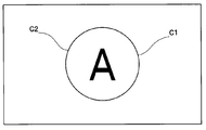
- FIG. 3 is a schematic diagram of a display image of the monitor 5 in the middle-distance observation state of the stereoscopic endoscope apparatus 1 according to the first embodiment of the present invention.
- the right-eye image C1 and the left-eye image C2 acquired from the variable focus objective optical system 41 are displayed so as to overlap each other because they do not have parallax. It is represented by a circle with.
- FIG. 4 is a schematic diagram of a display image of the monitor 5 in the near-point observation state of the stereoscopic endoscope apparatus 1 according to the first embodiment of the present invention.
- FIG. 4 shows a state in which two images having parallax are displayed on the monitor 5.
- the image C3 for the right eye acquired from the variable focus objective optical system 41 is schematically represented by a circle having an “A” character
- the image C4 for the left eye acquired by the fixed focus objective optical system 51 is schematically illustrated. In particular, it is represented by a circle having a “B” character.
- the image signal generation output unit 94 When the focal length of the variable focus objective optical system 41 and the focal length of the fixed focus objective optical system 51 are different from each other according to the image signal acquired from the imaging unit 61, the image signal generation output unit 94 When the in-subject image acquired by the optical system 41 is output as an image signal, and the focal length of the variable focus objective optical system 41 and the focal length of the fixed focus objective optical system 51 coincide with each other, it is for three-dimensional display. Two in-subject images acquired by the variable focus objective optical system 41 and the fixed focus objective optical system 51 are output as image signals.
- the image signal generation / output unit 94 automatically converts the image signal into an image corresponding to stereoscopic observation. Switch to signal and output.
- the image signal generation output unit 94 is connected to a monitor 5 that displays an observation image.
- the image signal generation / output unit 94 acquires an image signal based on the imaging signal output from the imaging unit 61 via the CCU 92 and the control unit 93. Further, the image signal generation output unit 94 acquires a control signal from the control unit 93.
- the image signal generation / output unit 94 When the control signal acquired from the control unit 93 is a control signal instructing generation of an image for two-dimensional display, the image signal generation / output unit 94 outputs the image acquired by the variable focus objective optical system 41 to the right. Two-dimensional display image signals, which are the eye image C ⁇ b> 1 and the left eye image C ⁇ b> 2, are generated and output to the monitor 5.
- the right-eye image C1 and the left-eye image C2 acquired by the variable focus objective optical system 41 are the same images having no parallax.
- the image signal generation / output unit 94 displays the image acquired by the variable focus objective optical system 41 as the right eye.
- a signal of a three-dimensional display image having the image C3 and the image acquired by the fixed focus objective optical system 51 as the left-eye image C4 is generated and output to the monitor 5.
- variable focus objective optical system 41 When the arrangement of the variable focus objective optical system 41 and the fixed focus objective optical system 51 is reversed, the image acquired by the variable focus objective optical system 41 is set as the left-eye image C4, and the fixed focus objective optical system 51 is used. Let the image acquired by the above be the image C3 for the right eye.
- the right-eye image C3 acquired by the variable focus objective optical system 41 and the left-eye image C4 acquired by the fixed focus objective optical system 51 in the three-dimensional display image are acquired from the same subject. It is an image having parallax.
- the monitor 5 displays an image based on the image signal transmitted from the image signal generation output unit 94.
- the surgeon wears a stereoscopic glass such as a polarizing glass and displays a three-dimensional display image having left and right binocular parallax displayed on the monitor 5 or a two-dimensional display having no left and right binocular parallax. The image can be observed.
- a central processing unit (CPU) of the control unit 93 configures a determination unit 95 from a storage unit, Other processing programs and setting data are read and processing is started.
- the surgeon wears stereoscopic glasses.
- the surgeon inserts the insertion portion 21 of the endoscope 2 into the subject in order to perform a screening examination of the observation site from a remote position.
- the operator operates the operation lever 32 to place the variable focus objective optical system 41 in the mid-range point observation state.
- the focus adjusting unit 71 transmits a setting signal notifying that the variable focus objective optical system 41 is in the mid-range point observation state to the control unit 93.
- the control unit 93 receives from the focus adjustment unit 71 a setting signal for informing that the variable focus objective optical system 41 is in the middle-far point observation state, a control signal for instructing generation of a two-dimensional display image, and the variable focus objective optical
- the image signal acquired from the system 41 is output to the image signal generation / output unit 94.
- the image signal generation / output unit 94 uses the signal of the right eye image C1 and the right eye image C1 as a two-dimensional display image from the image signal acquired from the variable focus objective optical system 41 acquired from the control unit 93. And a signal of the left-eye image C ⁇ b> 2 that is the same image as is generated and output to the monitor 5.
- the monitor 5 acquires the signal of the two-dimensional display image from the image signal generation output unit 94 and displays the two-dimensional display image.
- a signal for the right eye image C1 and a signal for the left eye image C2 are generated and output to the monitor 5, so that the surgeon wears the stereoscopic glasses.
- the two-dimensional display image displayed on the monitor 5 can be observed.
- the operator wearing the stereoscopic glasses operates the operation lever 32 while viewing the two-dimensional display image displayed on the monitor 5 and adjusts the focal length of the variable focus objective optical system 41 so as to match the observation site. To burn. Thereby, the two-dimensional display image (FIG. 3) obtained by observing the observation site from a remote position is displayed on the monitor 5 in a focused state. The surgeon screens the observation site from a remote position while looking at the monitor 5.
- the surgeon moves the endoscope 2 close to the observation part while operating the operation lever 32 of the focus adjustment unit 71 while wearing the stereoscopic glass so as to examine the observation part from the close position. Then, the variable focus objective optical system 41 is set to the near point observation state.
- the focus adjusting unit 71 transmits a setting signal that informs the control unit 93 that the variable focus objective optical system 41 is in the near point observation state.
- the control unit 93 receives a setting signal informing that the variable focus objective optical system 41 is in the near-point observation state from the focus adjustment unit 71, and a control signal for instructing generation of an image for three-dimensional display, and the variable focus objective optical
- the image signal acquired from the system 41 and the image signal acquired from the fixed focus objective optical system 51 are output to the image signal generation output unit 94.
- the image signal generation output unit 94 receives a control signal instructing generation of a three-dimensional display image from the control unit 93, thereby obtaining an image signal acquired from the variable focus objective optical system 41 as a three-dimensional display image.
- a signal for the right eye image C3 is generated
- a signal for the left eye image C4 is generated based on the image signal acquired from the fixed focus objective optical system, and the signal is output to the monitor 5.
- the monitor 5 acquires a 3D display image signal from the image signal generation / output unit 94 and displays the 3D display image.
- the surgeon wearing the stereoscopic glasses observes the observation site from the close position by stereoscopic vision while looking at the monitor 5.
- the stereoscopic endoscope apparatus 1 has a changed focal length, and can display a two-dimensional display image when observing a middle distance point, and observes a near point.
- the image can be automatically switched to a three-dimensional display image.
- the determination unit 95 reads the signal transmitted from the focus adjustment unit 71 and determines whether or not the variable focus objective optical system 41 is in the near-point observation state.
- the second embodiment The determination unit 95 detects whether the fixed focus objective optical system 51 is focused on the observation site from the image acquired by the fixed focus objective optical system 51, and the variable focus objective optical system 41 is It is determined whether or not it is in the near point observation state. Note that description of the same configuration as in the first embodiment is omitted.
- FIG. 5 is a schematic diagram showing a state in which the message M is displayed on the monitor 5 of the stereoscopic endoscope apparatus 1 according to the second embodiment of the present invention.
- the determination unit 95 is configured to be able to determine whether or not the fixed-focus objective optical system 51 is in focus with respect to the observation site when displaying a two-dimensional display image.
- the determination unit 95 extracts a high-frequency component from the image acquired by the fixed focus objective optical system 51, obtains a contrast evaluation value by integrating the high-frequency component, and evaluates the contrast evaluation value. It is determined whether or not the fixed focus objective optical system 51 is in focus.
- the control unit 93 changes the variable focus objective optical system 41.
- a message M for notifying the surgeon that the image can be switched to the three-dimensional display image is generated and added, and output to the image signal generation / output unit 94.
- the image signal generation / output unit 94 acquires an image signal to which the message M is added from the control unit 93, generates an image signal for two-dimensional display, and outputs the image signal to the monitor 5.
- the monitor 5 acquires the signal of the two-dimensional display image to which the message M is added from the image signal generation / output unit 94, and displays the two-dimensional display image to which the message M is added.
- the control unit 93 controls the generation of the 3D display image.
- the image signal acquired by the variable focus objective optical system 41 and the image signal acquired by the fixed focus objective optical system 51 are output to the image signal generation output unit 94.
- the image signal generation / output unit 94 receives a control signal instructing generation of a three-dimensional display image from the control unit 93, and the right side of the image acquired from the variable focus objective optical system 41 as a three-dimensional display image.
- An eye image C3 is generated, and a left eye image C4 is generated from an image acquired from the fixed focus objective optical system 51.
- the image signal generation / output unit 94 converts a three-dimensional display image composed of the right-eye image C3 and the left-eye image C4 into a signal and outputs the signal to the monitor 5.
- the monitor 5 acquires a 3D display image signal from the image signal generation output unit 94 and displays the 3D display image on the monitor 5.
- the surgeon can select whether to display a two-dimensional display image or a three-dimensional display image. Can be displayed on a monitor.
- the message M notifies that the display of the three-dimensional display image is possible. Is displayed on the monitor 5, but when the determination unit 95 determines that the fixed focus objective optical system 51 is focused on the observation site, the variable focus objective optical system 41 is automatically observed at the near point. It is good also as a structure which switches to a state and switches the display of the monitor 5 from a two-dimensional display image to a three-dimensional display image.
- the control unit 93 sets the movable lens 44 to a predetermined position near the imaging unit 61 with respect to the focus adjustment unit 71.
- a control signal is transmitted to bring the variable focus objective optical system 41 into a near-point observation state.
- the focus adjustment unit 71 that has received the control signal from the control unit 93 moves the movable lens 44 to a position closest to the imaging unit 61, and puts the variable focus objective optical system 41 into a near-point observation state.
- the imaging unit 61 captures an image having parallax from the variable focus objective optical system 41 and the fixed focus objective optical system 51 and outputs an imaging signal to the CCU 92.
- the CCU 92 converts the imaging signal acquired from the imaging unit 61 into an image signal, and then outputs the image signal to the control unit 93.
- the control unit 93 generates a control signal instructing generation of an image for three-dimensional display, an image signal acquired by the variable focus objective optical system 41, and an image signal acquired by the fixed focus objective optical system 51. It transmits to the signal generation output part 94.
- the image signal generation / output unit 94 generates a three-dimensional display image signal based on the signal received from the control unit 93 and outputs the signal to the monitor 5.
- the fixed focus objective optical system 51 when the surgeon grasps in advance the observation site to be observed from the three-dimensional display image, the fixed focus objective optical system 51 is arranged at a position where it can be focused close to the observation site. Then, the determination unit 95 determines that the fixed focus objective optical system 51 is in focus, and automatically switches to a three-dimensional display image. Therefore, the operation is simple and quick switching to the three-dimensional display image is possible.
- a stereoscopic endoscope apparatus can be provided.
- the imaging unit 61 is configured by one imaging element, but the imaging unit 61 is for the variable focus objective optical system 41.
- a configuration having two image pickup elements including the image pickup element and the image pickup element for the fixed focus objective optical system 51 may be used.
- the focus adjustment unit 71 has an electric actuator and has a configuration in which the movable lens is moved electrically.
- the unit 71 may be configured to move the movable lens manually, that is, with power generated by manual operation of the operation lever 32.
- the variable focus objective optical system 41 is configured to be adjustable to an arbitrary focal length by adjusting the position of the movable lens 44.
- the focal length at the far point observation (far point observation state) or the focal length at the near point observation (near point observation state) may be switched.
- the image signal generation / output unit 94 receives the object acquired by the variable focus objective optical system 41 for displaying the two-dimensional display image on the monitor 5.
- the signal of the in-specimen image is output.
- the image signal generation output unit 94 is fixed to the variable focus objective optical system 41 for displaying the three-dimensional display image on the monitor 5.
- a signal of the in-subject image acquired by the focus objective optical system 51 is output. According to this configuration, it is possible to immediately switch from the far point observation state to the near point observation state, and it is possible to shorten the time required for changing the focal length.
- the control unit 93 acquires the fixed focus objective optical system 51. However, the control unit 93 transmits the image signal acquired by the fixed focus objective optical system 51 to the image signal generation / output unit 94 and transmits the image to the image signal generation / output unit 94. On the signal generation / output unit 94 side, the image signal acquired by the fixed focus objective optical system 51 may not be output to the monitor.
- the image signal generation / output unit 94 is a three-dimensional display image.
- an image signal acquired by the variable focus objective optical system 41 and an image signal acquired by the fixed focus objective optical system 51 are output.
- the signal of each image is output from the image signal generation / output unit 94, it is acquired by the variable focus objective optical system 41 by a switch (not shown) provided between the monitor 5 or the function of the monitor 5. Only the image may be displayed on the monitor 5 as a two-dimensional display image.
- the right-eye image C1 from the image acquired by the variable focus objective optical system 41 is displayed.
- a signal for a two-dimensional display image as the left-eye image C2 is generated and output to the monitor 5, but the variable-focus objective optics are not generated without generating the signals for the right-eye image C1 and the left-eye image C2.
- the image signal acquired by the system 41 may be directly transmitted to the monitor 5 for display. According to this configuration, the operator can observe the two-dimensional display image in a state where the stereoscopic glass is removed.
- the setting of the monitor 5 is switched so as to display the three-dimensional display image. Observe the 3D display image.
- a stereoscopic endoscope apparatus that can change the focal length and can perform stereoscopic observation at a near point.
Landscapes
- Health & Medical Sciences (AREA)
- Life Sciences & Earth Sciences (AREA)
- Physics & Mathematics (AREA)
- Surgery (AREA)
- Engineering & Computer Science (AREA)
- Optics & Photonics (AREA)
- General Health & Medical Sciences (AREA)
- Radiology & Medical Imaging (AREA)
- Medical Informatics (AREA)
- Biophysics (AREA)
- Biomedical Technology (AREA)
- Heart & Thoracic Surgery (AREA)
- Nuclear Medicine, Radiotherapy & Molecular Imaging (AREA)
- Molecular Biology (AREA)
- Animal Behavior & Ethology (AREA)
- Pathology (AREA)
- Public Health (AREA)
- Veterinary Medicine (AREA)
- General Physics & Mathematics (AREA)
- Signal Processing (AREA)
- Multimedia (AREA)
- Astronomy & Astrophysics (AREA)
- Endoscopes (AREA)
- Instruments For Viewing The Inside Of Hollow Bodies (AREA)
Abstract
On décrit un dispositif endoscope stéréoscopique qui comprend: une pièce d'insertion (21) s'insérant dans un sujet d'essai; un système optique à objectif à focale variable (41) et un système optique à objectif à focale fixe (51) positionnés à l'intérieur de la section d'extrémité de pointe (22) de la pièce d'insertion (21); une unité d'imagerie (61) pour capturer une image optique; et une unité de sortie d'émission de signal d'image (94) pour produire une image interne d'un sujet d'imagerie qui est obtenue par le système optique à objectif à focale variable (41) et fonctionne comme un signal d'image lorsque la longueur focale du système optique à objectif à focale variable (41) et celle du système optique à objectif à focale fixe (51) diffèrent l'une de l'autre, et pour produire une image interne du sujet d'imagerie obtenue par le système optique à objectif à focale variable (41) et le système optique à objectif à focale fixe (51) et fonctionne comme un signal d'image lorsque la longueur focale du système optique à objectif à focale variable (41) et celle du système optique à objectif à focale fixe (51) correspondent l'une avec l'autre.
Priority Applications (4)
| Application Number | Priority Date | Filing Date | Title |
|---|---|---|---|
| EP16792463.8A EP3275359A1 (fr) | 2015-05-12 | 2016-04-11 | Dispositif endoscope stéréoscopique |
| JP2016563154A JP6153675B2 (ja) | 2015-05-12 | 2016-04-11 | 立体内視鏡装置 |
| CN201680013612.1A CN107405049B (zh) | 2015-05-12 | 2016-04-11 | 立体内窥镜装置 |
| US15/796,915 US10750937B2 (en) | 2015-05-12 | 2017-10-30 | Stereoscopic endoscope apparatus having variable focus and fixed focus objective optical systems |
Applications Claiming Priority (2)
| Application Number | Priority Date | Filing Date | Title |
|---|---|---|---|
| JP2015-097683 | 2015-05-12 | ||
| JP2015097683 | 2015-05-12 |
Related Child Applications (1)
| Application Number | Title | Priority Date | Filing Date |
|---|---|---|---|
| US15/796,915 Continuation US10750937B2 (en) | 2015-05-12 | 2017-10-30 | Stereoscopic endoscope apparatus having variable focus and fixed focus objective optical systems |
Publications (1)
| Publication Number | Publication Date |
|---|---|
| WO2016181738A1 true WO2016181738A1 (fr) | 2016-11-17 |
Family
ID=57247886
Family Applications (1)
| Application Number | Title | Priority Date | Filing Date |
|---|---|---|---|
| PCT/JP2016/061712 WO2016181738A1 (fr) | 2015-05-12 | 2016-04-11 | Dispositif endoscope stéréoscopique |
Country Status (5)
| Country | Link |
|---|---|
| US (1) | US10750937B2 (fr) |
| EP (1) | EP3275359A1 (fr) |
| JP (1) | JP6153675B2 (fr) |
| CN (1) | CN107405049B (fr) |
| WO (1) | WO2016181738A1 (fr) |
Cited By (2)
| Publication number | Priority date | Publication date | Assignee | Title |
|---|---|---|---|---|
| WO2018105044A1 (fr) * | 2016-12-07 | 2018-06-14 | オリンパス株式会社 | Dispositif d'imagerie stéréoscopique et endoscope stéréoscopique |
| JP2019195520A (ja) * | 2018-05-10 | 2019-11-14 | オリンパス株式会社 | 内視鏡装置、内視鏡装置における照明光学系の切り替え方法、プログラム、および記録媒体 |
Citations (6)
| Publication number | Priority date | Publication date | Assignee | Title |
|---|---|---|---|---|
| JPH095643A (ja) * | 1995-06-26 | 1997-01-10 | Matsushita Electric Ind Co Ltd | 立体内視鏡装置 |
| JP2004536648A (ja) * | 2001-08-02 | 2004-12-09 | ギブン・イメージング・リミテッド | インビボ画像化のための装置および方法 |
| JP2005143991A (ja) * | 2003-11-18 | 2005-06-09 | Olympus Corp | カプセル型医療システム |
| JP2006093860A (ja) * | 2004-09-21 | 2006-04-06 | Olympus Corp | 2眼撮像系を搭載したカメラ |
| WO2011132552A1 (fr) * | 2010-04-22 | 2011-10-27 | コニカミノルタホールディングス株式会社 | Dispositif de traitement d'informations, programme, procédé de traitement d'informations, et système de traitement d'informations |
| JP2014140593A (ja) * | 2013-01-25 | 2014-08-07 | Fujifilm Corp | 立体内視鏡装置 |
Family Cites Families (16)
| Publication number | Priority date | Publication date | Assignee | Title |
|---|---|---|---|---|
| JPH0829701A (ja) * | 1994-07-18 | 1996-02-02 | Olympus Optical Co Ltd | 立体視内視鏡システム |
| JPH08262333A (ja) | 1995-03-27 | 1996-10-11 | Terumo Corp | 立体内視鏡システム |
| KR100436538B1 (ko) * | 1995-06-07 | 2004-09-16 | 제이콥 엔 올스테드터 | 3차원영상화시스템 |
| US6767321B2 (en) * | 1999-10-04 | 2004-07-27 | Robert Czarnek | Stereo laparoscope with discrete working distance |
| US6898022B2 (en) * | 2002-06-20 | 2005-05-24 | Olympus Corporation | Stereo optical system pair for stereo endoscope system |
| JP4179946B2 (ja) * | 2003-08-08 | 2008-11-12 | オリンパス株式会社 | 立体内視鏡装置 |
| CN102141640A (zh) * | 2003-10-23 | 2011-08-03 | 安德里斯·奥布雷斯基 | 成像光学系统及生成物体的放大立体图像的立体显微系统 |
| EP1763258B1 (fr) * | 2005-09-09 | 2010-11-03 | Olympus Medical Systems Corp. | Système d'observation stéréo médical |
| KR101598653B1 (ko) * | 2009-07-10 | 2016-02-29 | 아이씨3디 인크. | 단일 이미징 경로를 사용하여 3차원 이미지 정보를 발생시키는 방법 및 장치 |
| JP5609562B2 (ja) * | 2010-11-10 | 2014-10-22 | ソニー株式会社 | 立体画像撮像装置 |
| JP5965726B2 (ja) * | 2012-05-24 | 2016-08-10 | オリンパス株式会社 | 立体視内視鏡装置 |
| WO2014021134A1 (fr) * | 2012-07-30 | 2014-02-06 | オリンパス株式会社 | Dispositif de capture d'image et procédé de capture d'image |
| JP6103849B2 (ja) * | 2012-08-02 | 2017-03-29 | オリンパス株式会社 | 内視鏡装置及び内視鏡装置の作動方法 |
| JP5730339B2 (ja) * | 2013-01-25 | 2015-06-10 | 富士フイルム株式会社 | 立体内視鏡装置 |
| WO2014122843A1 (fr) * | 2013-02-06 | 2014-08-14 | オリンパスメディカルシステムズ株式会社 | Endoscope stéréoscopique |
| JP5897222B2 (ja) * | 2013-12-05 | 2016-03-30 | オリンパス株式会社 | 立体内視鏡システム |
-
2016
- 2016-04-11 CN CN201680013612.1A patent/CN107405049B/zh active Active
- 2016-04-11 JP JP2016563154A patent/JP6153675B2/ja active Active
- 2016-04-11 EP EP16792463.8A patent/EP3275359A1/fr not_active Withdrawn
- 2016-04-11 WO PCT/JP2016/061712 patent/WO2016181738A1/fr unknown
-
2017
- 2017-10-30 US US15/796,915 patent/US10750937B2/en active Active
Patent Citations (6)
| Publication number | Priority date | Publication date | Assignee | Title |
|---|---|---|---|---|
| JPH095643A (ja) * | 1995-06-26 | 1997-01-10 | Matsushita Electric Ind Co Ltd | 立体内視鏡装置 |
| JP2004536648A (ja) * | 2001-08-02 | 2004-12-09 | ギブン・イメージング・リミテッド | インビボ画像化のための装置および方法 |
| JP2005143991A (ja) * | 2003-11-18 | 2005-06-09 | Olympus Corp | カプセル型医療システム |
| JP2006093860A (ja) * | 2004-09-21 | 2006-04-06 | Olympus Corp | 2眼撮像系を搭載したカメラ |
| WO2011132552A1 (fr) * | 2010-04-22 | 2011-10-27 | コニカミノルタホールディングス株式会社 | Dispositif de traitement d'informations, programme, procédé de traitement d'informations, et système de traitement d'informations |
| JP2014140593A (ja) * | 2013-01-25 | 2014-08-07 | Fujifilm Corp | 立体内視鏡装置 |
Cited By (4)
| Publication number | Priority date | Publication date | Assignee | Title |
|---|---|---|---|---|
| WO2018105044A1 (fr) * | 2016-12-07 | 2018-06-14 | オリンパス株式会社 | Dispositif d'imagerie stéréoscopique et endoscope stéréoscopique |
| CN110049708A (zh) * | 2016-12-07 | 2019-07-23 | 奥林巴斯株式会社 | 立体摄像装置和立体内窥镜 |
| JP2019195520A (ja) * | 2018-05-10 | 2019-11-14 | オリンパス株式会社 | 内視鏡装置、内視鏡装置における照明光学系の切り替え方法、プログラム、および記録媒体 |
| JP7117894B2 (ja) | 2018-05-10 | 2022-08-15 | 株式会社エビデント | 内視鏡装置、内視鏡装置における照明光学系の切り替え方法、プログラム、および記録媒体 |
Also Published As
| Publication number | Publication date |
|---|---|
| EP3275359A1 (fr) | 2018-01-31 |
| US20180042465A1 (en) | 2018-02-15 |
| JP6153675B2 (ja) | 2017-06-28 |
| CN107405049B (zh) | 2020-05-26 |
| JPWO2016181738A1 (ja) | 2017-06-01 |
| CN107405049A (zh) | 2017-11-28 |
| US10750937B2 (en) | 2020-08-25 |
Similar Documents
| Publication | Publication Date | Title |
|---|---|---|
| JP5695808B1 (ja) | 内視鏡装置 | |
| JP5730339B2 (ja) | 立体内視鏡装置 | |
| JP2017509925A (ja) | 3dビデオ顕微鏡装置 | |
| US20120300032A1 (en) | Endoscope | |
| JP6553130B2 (ja) | ステレオビデオ内視鏡の光学系と、ステレオビデオ内視鏡とステレオビデオ内視鏡の光学系を操作するための方法 | |
| JP6329715B1 (ja) | 内視鏡システムおよび内視鏡 | |
| JP2010057619A (ja) | 立体画像撮影表示システム | |
| JP6210874B2 (ja) | 立体観察装置の調整治具及び立体観察システム | |
| JP7123053B2 (ja) | 医療用観察装置 | |
| JPH06202006A (ja) | 立体視硬性内視鏡 | |
| JP6253857B1 (ja) | 立体内視鏡および立体内視鏡システム | |
| JP2014110910A (ja) | 立体内視鏡装置 | |
| JP6153675B2 (ja) | 立体内視鏡装置 | |
| JP5946777B2 (ja) | 立体撮像装置 | |
| KR101339667B1 (ko) | 의료 수술용 현미경의 3차원 고화질 영상 인터페이스 시스템 | |
| JP5802869B1 (ja) | 外科用デバイス | |
| JP6368886B1 (ja) | 内視鏡システム | |
| JP2002085330A (ja) | 立体視内視鏡装置 | |
| WO2021131921A1 (fr) | Dispositif à miroir rigide | |
| JP2004233480A (ja) | 立体内視鏡システム | |
| WO2021176717A1 (fr) | Dispositif endoscopique, processeur pour image endoscopique et procédé de génération d'image endoscopique | |
| JP2017106994A (ja) | 手術用立体観察装置 | |
| WO2017098755A1 (fr) | Appareil d'imagerie stéréoscopique | |
| ITGE20090099A1 (it) | Dispositivo endoscopico stereoscopico richiudibile con regolazione continua della convergenza. |
Legal Events
| Date | Code | Title | Description |
|---|---|---|---|
| ENP | Entry into the national phase |
Ref document number: 2016563154 Country of ref document: JP Kind code of ref document: A |
|
| 121 | Ep: the epo has been informed by wipo that ep was designated in this application |
Ref document number: 16792463 Country of ref document: EP Kind code of ref document: A1 |
|
| NENP | Non-entry into the national phase |
Ref country code: DE |