WO2016181713A1 - 動力伝達装置およびこれを備える動力出力装置 - Google Patents
動力伝達装置およびこれを備える動力出力装置 Download PDFInfo
- Publication number
- WO2016181713A1 WO2016181713A1 PCT/JP2016/059898 JP2016059898W WO2016181713A1 WO 2016181713 A1 WO2016181713 A1 WO 2016181713A1 JP 2016059898 W JP2016059898 W JP 2016059898W WO 2016181713 A1 WO2016181713 A1 WO 2016181713A1
- Authority
- WO
- WIPO (PCT)
- Prior art keywords
- gear
- shaft
- meshing
- lubricating oil
- power transmission
- Prior art date
- Legal status (The legal status is an assumption and is not a legal conclusion. Google has not performed a legal analysis and makes no representation as to the accuracy of the status listed.)
- Ceased
Links
Images










Classifications
-
- B—PERFORMING OPERATIONS; TRANSPORTING
- B60—VEHICLES IN GENERAL
- B60K—ARRANGEMENT OR MOUNTING OF PROPULSION UNITS OR OF TRANSMISSIONS IN VEHICLES; ARRANGEMENT OR MOUNTING OF PLURAL DIVERSE PRIME-MOVERS IN VEHICLES; AUXILIARY DRIVES FOR VEHICLES; INSTRUMENTATION OR DASHBOARDS FOR VEHICLES; ARRANGEMENTS IN CONNECTION WITH COOLING, AIR INTAKE, GAS EXHAUST OR FUEL SUPPLY OF PROPULSION UNITS IN VEHICLES
- B60K6/00—Arrangement or mounting of plural diverse prime-movers for mutual or common propulsion, e.g. hybrid propulsion systems comprising electric motors and internal combustion engines
- B60K6/20—Arrangement or mounting of plural diverse prime-movers for mutual or common propulsion, e.g. hybrid propulsion systems comprising electric motors and internal combustion engines the prime-movers consisting of electric motors and internal combustion engines, e.g. HEVs
- B60K6/22—Arrangement or mounting of plural diverse prime-movers for mutual or common propulsion, e.g. hybrid propulsion systems comprising electric motors and internal combustion engines the prime-movers consisting of electric motors and internal combustion engines, e.g. HEVs characterised by apparatus, components or means specially adapted for HEVs
- B60K6/40—Arrangement or mounting of plural diverse prime-movers for mutual or common propulsion, e.g. hybrid propulsion systems comprising electric motors and internal combustion engines the prime-movers consisting of electric motors and internal combustion engines, e.g. HEVs characterised by apparatus, components or means specially adapted for HEVs characterised by the assembly or relative disposition of components
- B60K6/405—Housings
-
- B—PERFORMING OPERATIONS; TRANSPORTING
- B60—VEHICLES IN GENERAL
- B60K—ARRANGEMENT OR MOUNTING OF PROPULSION UNITS OR OF TRANSMISSIONS IN VEHICLES; ARRANGEMENT OR MOUNTING OF PLURAL DIVERSE PRIME-MOVERS IN VEHICLES; AUXILIARY DRIVES FOR VEHICLES; INSTRUMENTATION OR DASHBOARDS FOR VEHICLES; ARRANGEMENTS IN CONNECTION WITH COOLING, AIR INTAKE, GAS EXHAUST OR FUEL SUPPLY OF PROPULSION UNITS IN VEHICLES
- B60K6/00—Arrangement or mounting of plural diverse prime-movers for mutual or common propulsion, e.g. hybrid propulsion systems comprising electric motors and internal combustion engines
- B60K6/20—Arrangement or mounting of plural diverse prime-movers for mutual or common propulsion, e.g. hybrid propulsion systems comprising electric motors and internal combustion engines the prime-movers consisting of electric motors and internal combustion engines, e.g. HEVs
- B60K6/22—Arrangement or mounting of plural diverse prime-movers for mutual or common propulsion, e.g. hybrid propulsion systems comprising electric motors and internal combustion engines the prime-movers consisting of electric motors and internal combustion engines, e.g. HEVs characterised by apparatus, components or means specially adapted for HEVs
- B60K6/40—Arrangement or mounting of plural diverse prime-movers for mutual or common propulsion, e.g. hybrid propulsion systems comprising electric motors and internal combustion engines the prime-movers consisting of electric motors and internal combustion engines, e.g. HEVs characterised by apparatus, components or means specially adapted for HEVs characterised by the assembly or relative disposition of components
-
- B—PERFORMING OPERATIONS; TRANSPORTING
- B60—VEHICLES IN GENERAL
- B60K—ARRANGEMENT OR MOUNTING OF PROPULSION UNITS OR OF TRANSMISSIONS IN VEHICLES; ARRANGEMENT OR MOUNTING OF PLURAL DIVERSE PRIME-MOVERS IN VEHICLES; AUXILIARY DRIVES FOR VEHICLES; INSTRUMENTATION OR DASHBOARDS FOR VEHICLES; ARRANGEMENTS IN CONNECTION WITH COOLING, AIR INTAKE, GAS EXHAUST OR FUEL SUPPLY OF PROPULSION UNITS IN VEHICLES
- B60K6/00—Arrangement or mounting of plural diverse prime-movers for mutual or common propulsion, e.g. hybrid propulsion systems comprising electric motors and internal combustion engines
- B60K6/20—Arrangement or mounting of plural diverse prime-movers for mutual or common propulsion, e.g. hybrid propulsion systems comprising electric motors and internal combustion engines the prime-movers consisting of electric motors and internal combustion engines, e.g. HEVs
- B60K6/42—Arrangement or mounting of plural diverse prime-movers for mutual or common propulsion, e.g. hybrid propulsion systems comprising electric motors and internal combustion engines the prime-movers consisting of electric motors and internal combustion engines, e.g. HEVs characterised by the architecture of the hybrid electric vehicle
- B60K6/46—Series type
-
- B—PERFORMING OPERATIONS; TRANSPORTING
- B60—VEHICLES IN GENERAL
- B60L—PROPULSION OF ELECTRICALLY-PROPELLED VEHICLES; SUPPLYING ELECTRIC POWER FOR AUXILIARY EQUIPMENT OF ELECTRICALLY-PROPELLED VEHICLES; ELECTRODYNAMIC BRAKE SYSTEMS FOR VEHICLES IN GENERAL; MAGNETIC SUSPENSION OR LEVITATION FOR VEHICLES; MONITORING OPERATING VARIABLES OF ELECTRICALLY-PROPELLED VEHICLES; ELECTRIC SAFETY DEVICES FOR ELECTRICALLY-PROPELLED VEHICLES
- B60L50/00—Electric propulsion with power supplied within the vehicle
- B60L50/10—Electric propulsion with power supplied within the vehicle using propulsion power supplied by engine-driven generators, e.g. generators driven by combustion engines
- B60L50/16—Electric propulsion with power supplied within the vehicle using propulsion power supplied by engine-driven generators, e.g. generators driven by combustion engines with provision for separate direct mechanical propulsion
-
- F—MECHANICAL ENGINEERING; LIGHTING; HEATING; WEAPONS; BLASTING
- F16—ENGINEERING ELEMENTS AND UNITS; GENERAL MEASURES FOR PRODUCING AND MAINTAINING EFFECTIVE FUNCTIONING OF MACHINES OR INSTALLATIONS; THERMAL INSULATION IN GENERAL
- F16H—GEARING
- F16H1/00—Toothed gearings for conveying rotary motion
- F16H1/02—Toothed gearings for conveying rotary motion without gears having orbital motion
- F16H1/04—Toothed gearings for conveying rotary motion without gears having orbital motion involving only two intermeshing members
- F16H1/06—Toothed gearings for conveying rotary motion without gears having orbital motion involving only two intermeshing members with parallel axes
-
- F—MECHANICAL ENGINEERING; LIGHTING; HEATING; WEAPONS; BLASTING
- F16—ENGINEERING ELEMENTS AND UNITS; GENERAL MEASURES FOR PRODUCING AND MAINTAINING EFFECTIVE FUNCTIONING OF MACHINES OR INSTALLATIONS; THERMAL INSULATION IN GENERAL
- F16H—GEARING
- F16H57/00—General details of gearing
- F16H57/04—Features relating to lubrication or cooling or heating
-
- Y—GENERAL TAGGING OF NEW TECHNOLOGICAL DEVELOPMENTS; GENERAL TAGGING OF CROSS-SECTIONAL TECHNOLOGIES SPANNING OVER SEVERAL SECTIONS OF THE IPC; TECHNICAL SUBJECTS COVERED BY FORMER USPC CROSS-REFERENCE ART COLLECTIONS [XRACs] AND DIGESTS
- Y02—TECHNOLOGIES OR APPLICATIONS FOR MITIGATION OR ADAPTATION AGAINST CLIMATE CHANGE
- Y02T—CLIMATE CHANGE MITIGATION TECHNOLOGIES RELATED TO TRANSPORTATION
- Y02T10/00—Road transport of goods or passengers
- Y02T10/60—Other road transportation technologies with climate change mitigation effect
- Y02T10/62—Hybrid vehicles
Definitions
- the present invention transmits the power from the internal combustion engine input via the output shaft of the internal combustion engine to the rotating shaft of the generator and the power from the motor input via the rotating shaft of the motor to the drive shaft.
- the present invention relates to a power transmission device configured to transmit to a power transmission device and a power output device including the same.
- JP 2010-247786 Patent Document 1
- an engine crankshaft and a generator rotation shaft are connected via a generator drive gear train, and a motor rotation shaft and a differential device differential shaft are connected to a motor.
- a power transmission device that is connected via a driving force transmission gear train and a final gear train to transmit power from an engine to a generator and to transmit power from a motor to an output shaft.
- the power transmission device includes an oil pump driven by the engine, even when only the engine is driven with the motor stopped for the purpose of charging electric power, each part of the device, particularly the generator
- the drive gear train can be lubricated satisfactorily.
- the present invention has been made in view of the above, and an object of the present invention is to provide a technique capable of ensuring the lubricity of each part of the apparatus while reducing the number of parts and making the apparatus compact.
- the power transmission device of the present invention and the power output device including the power transmission device employ the following means in order to achieve the above-described object.
- the power from the internal combustion engine input via the output shaft of the internal combustion engine is transmitted to the rotation shaft of the generator and input via the rotation shaft of the motor.
- the motive power from the motor is transmitted to the drive shaft.
- the power transmission device includes a first input shaft, a connection shaft, a first gear mechanism, a second gear mechanism, and a case member.
- the first input shaft is arranged in parallel to the drive shaft and is connected to the output shaft of the internal combustion engine.
- the connecting shaft is arranged in parallel to the first input shaft and is connected to the rotating shaft of the generator.
- the second input shaft is arranged in parallel to the drive shaft and is configured to be connected to the rotation shaft of the motor.
- the first gear mechanism is configured to connect the first input shaft and the connection shaft.
- the second gear mechanism is configured to connect the second input shaft and the drive shaft.
- the case member is configured to be able to store lubricating oil.
- the second gear mechanism has a drive gear configured such that at least a part thereof is always immersed in the lubricating oil stored in the case member.
- the case member has a holding part configured to hold the lubricating oil scraped up by the drive gear.
- the first gear mechanism has a scraping gear configured to be able to scrape the lubricating oil held in the holding portion. And it is comprised so that at least one part of the lubricating oil scraped up by the scraping gear may be guide
- the “lubricating oil scraped up by the scraping gear” includes not only the lubricating oil scraped up and scattered by the scraping gear but also other gears that are scraped up by the scraping gear and mesh with the scraping gear. After being transported to the meshing portion, the lubricating oil splashed from the meshing portion, or the lubricating oil scattered from the meshing portion to the other gear in the rotational direction of the other gear Are preferably included.
- the drive gear since at least a part of the drive gear is always immersed in the lubricant stored in the bottom of the case member, when the motor is driven, the drive gear scrapes up the lubricant.
- Each part of the apparatus can be lubricated.
- the scraping gear is configured to scrape the lubricating oil held in the holding portion, even when only the internal combustion engine is driven, each part of the device is lubricated by the lubricating oil that is scraped up by the scraping gear. Can do.
- the case member includes a guide portion configured to guide at least a part of the lubricating oil scraped up by the scraping gear to the holding portion.
- the lubricating oil scraped up by the scraping gear can be guided to the holding portion with a simple configuration in which only the guiding portion is provided on the case member.
- the guide portion has a protruding wall portion configured to protrude from the upper inner wall surface of the case member toward the holding portion. And it is comprised so that the lubricating oil which was scraped up by the scraping gear and collided with the upper inner wall surface may be guide
- the lubricating oil scraped up by the scraping gear can be guided to the holding portion with a simple configuration in which only the protruding wall portion is provided.
- the first gear mechanism has a meshing gear that meshes with the scraping gear.
- the scraping gear and the meshing gear are configured such that the lubricating oil scattered from the meshing portion between the scraping gear and the meshing gear is rotated in a direction toward the bottom of the case member.
- the guide portion is configured to guide at least a part of the lubricant oil that rotates around the meshing gear among the lubricant scattered from the meshing portion to the holding portion, and the first rotation direction of the drive gear
- a guide wall configured to guide at least part of the lubricating oil that is scraped up to the holding portion.
- the lubricating oil scattered from the meshing portion of the scraping gear and the meshing gear and rotating with the rotation of the meshing gear and the lubrication that is scraped up with the rotation of the drive gear in the first rotational direction Since at least a part of the oil is guided to the holding portion, it is possible to effectively suppress the absence of the lubricating oil held by the holding portion. Thereby, the lubricity by the lubricating oil which the scraping gear scrapes up can be ensured more stably.
- the first input shaft, the connection shaft, the second input shaft, and the drive shaft when viewed from the axial direction, are the center of the first input shaft and the connection shaft.
- the first virtual connection line connecting the axis centers and the second virtual connection line connecting the axis center of the second input shaft and the axis center of the drive shaft are arranged in a substantially inverted V shape.
- the second input shaft is arranged closer to the top of the inverted V shape than the drive shaft.
- the meshing gear and the scraping gear are arranged on the first virtual connecting line, and the meshing gear is arranged near the top of the V-shape than the scraping gear.
- the holding portion has an arc-shaped portion and an extending portion, and is configured as an isolation wall that separates the scraping gear and the bottom portion of the case member.
- the arcuate portion is disposed below the scraping gear and is configured to have substantially the same curvature as that of the scraping gear.
- the extending part is configured to extend from one end of the arcuate part to the lower part of the meshing gear substantially parallel to the first virtual connecting line.
- the guide wall is arranged at a position corresponding to between the meshing gear and the extending portion when viewed from the axial direction, and is configured to isolate the meshing gear and the drive gear. Further, the guide wall is configured such that one end of the guide wall overlaps with the extending portion in the extending direction of the extending portion.
- the first input shaft, the connection shaft, the second input shaft, and the drive shaft so that the first virtual connection line and the second virtual connection line form a substantially inverted V shape when viewed from the axial direction.
- the effect of the present invention can be made more remarkable. Since the guide wall and the extending portion overlap each other, the lubricating oil swirled by the meshing gear and colliding with the guiding wall and the lubricating oil scraped up by the drive gear and colliding with the guiding wall are efficiently transferred to the holding portion. Can be guided. Thereby, it can suppress more effectively that the lubricating oil hold
- the holding portion has a circular arc-shaped portion, it is possible to realize a smooth scraping of the lubricating oil by the scraping gear. Furthermore, since the holding portion has the extending portion, the lubricating oil that is scraped up by the drive gear and introduced into the holding portion can be smoothly guided to the arc-shaped portion.
- the guide wall is formed in an arc shape along the meshing gear.
- the power transmission device further includes a second guide wall configured to guide the lubricating oil scraped up with the rotation of the drive gear in the first rotation direction to the guide wall. Yes. And the said 2nd guide wall is comprised so that it may be connected to an extension part.
- the second gear mechanism includes a motor gear fixed to the second input shaft, a drive gear, a first intermediate gear meshing with the motor gear, A rotation shaft of the first intermediate gear, and a second intermediate gear fixed to the rotation shaft of the first intermediate gear and meshing with the drive gear.
- the second gear mechanism is configured such that the lubricating oil that is scraped up from the meshing portion of the drive gear and the second intermediate gear toward the guide wall is scraped up as the drive gear rotates in the second rotational direction.
- the guide wall is comprised so that the other end of the said guide wall may extend to the position which cross
- the lubricating oil that is scraped up from the meshing portion of the drive gear and the second intermediate gear with the rotation of the drive gear in the second rotation direction can be effectively collided with the guide wall. it can. Thereby, the amount of lubricating oil induced
- the configuration is such that the lubricating oil scraped up with the rotation of the drive gear in the second rotational direction is guided to the meshing portion of the drive gear and the second intermediate gear. And a third guiding wall.
- the lubricating oil can be efficiently guided to the meshing portion between the drive gear and the second intermediate gear.
- the protruding wall portion is disposed immediately above the rotation center of the scraping gear and the rotation center of the meshing gear. Note that the protruding wall portion may be disposed on the second virtual vertical line.
- the lubricating oil that flows down the projecting wall and collides with the scraping gear or the meshing gear is easily rotated in the rotational direction of the scraping gear and the meshing gear.
- the amount of lubricating oil scattered from the meshing part with the gear can be increased, and the lubricating oil can be guided to the holding part via the protruding wall part more effectively.
- the first gear mechanism further includes a second meshing gear that meshes with the scraping gear.
- the meshing gear is fixed to one of the first input shaft and the rotating shaft of the generator.
- the second meshing gear is fixed to the other of the first input shaft and the connecting shaft.
- the holding portion is disposed below the second meshing gear, has a second arcuate portion along the second meshing gear, and is configured to isolate the second meshing gear from the bottom portion of the case member. Yes.
- the second arcuate part is connected to the other end of the arcuate part.
- the lubricity of the first gear mechanism can be improved.
- the holding portion is configured to communicate the space in which the scraping gear is disposed and the space in which the bottom portion is disposed in the internal space of the case member. It has a communication part.
- the vicinity of the communication portion of the space in which the scraping gear is arranged among the case members can be made negative pressure than the space in which the bottom portion of the case member is disposed.
- Lubricating oil stored at the bottom can be introduced into the holding part via the communicating part.
- an internal combustion engine a generator that generates electric power as the internal combustion engine is driven, a motor that is driven by the electric power generated by the generator, and power from the motor
- a power transmission device according to the present invention according to any one of the above-described aspects configured to connect the internal combustion engine and the generator, and connect the motor and the drive shaft.
- the power transmission device since the power transmission device according to any one of the above-described aspects is provided, the same effects as the power transmission device according to the present invention, for example, the number of parts reduction and the compactness of the device are achieved. The effect that the lubricity of each part of the apparatus can be ensured can be achieved while achieving the above.
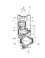
- FIG. 9 is an explanatory diagram of a configuration of a power transmission path on the engine 2 side in the power transmission device 20 as viewed from a direction corresponding to the AA cross section of FIG. 8.
- FIG. 9 is an explanatory view of the configuration of a power transmission path on the motor 4 side in the power transmission device 20 as viewed from a direction corresponding to a section BB in FIG. 8.
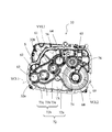
- 4 is a perspective view of a housing 32.
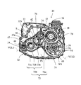
- FIG. 3 is a front view of a housing 32.
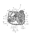
- FIG. 4 is a perspective view of a case body 34.
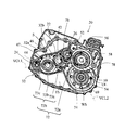
- FIG. 3 is a front view of a case body 34.
- FIG. 3 is a front view of a case body 34.
- FIG. 3 is a perspective view of the power transmission device 20 with a case body 34 removed.
- FIG. FIG. 5 is a perspective sectional view showing a VV section of FIG. 1.
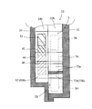
- FIG. 2 is a cross-sectional view showing a WW cross section of FIG. 1.
- a power output apparatus 1 includes a power transmission apparatus 20 according to an embodiment of the present invention, an engine 2, a motor 4 connected to the power transmission apparatus 20, and And a generator 6.
- the engine 2 is configured as an internal combustion engine that outputs power using a hydrocarbon fuel such as gasoline or light oil.
- the engine 2 outputs power by reciprocating a piston (not shown) by combustion pressure generated in a combustion chamber (not shown), and converting the reciprocating motion of the piston into the rotational motion of the crankshaft CS.
- the motor 4 includes a rotor (not shown) fixed to the motor rotating shaft 14 and a stator (not shown) provided coaxially with the rotor so as to surround the rotor. It is configured as a three-phase AC synchronous generator motor that can be driven as an electric motor and can also generate electric power as a generator. The motor 4 is driven by electric power supplied from a battery (not shown) via an inverter (not shown).
- the generator 6 includes a rotor (not shown) fixed to the generator rotating shaft 16 and a stator (not shown) provided coaxially with the rotor so as to surround the rotor.
- the generator rotating shaft 16 is configured as a three-phase AC synchronous generator that generates electric power by being rotated by the engine 2.
- the electric power generated by the generator 6 is stored in a battery (not shown) through an inverter (not shown).
- the power transmission device 20 includes a first input shaft 22 connected to the crankshaft CS via the flywheel FH, a first output shaft 24 connected to the generator rotating shaft 16, A first gear mechanism TM1 that connects the first input shaft 22 and the first output shaft 24, a second input shaft 26 that is connected to the motor rotating shaft 14, and a differential device that is connected to the axle WS, as shown in FIG. 28, a second gear mechanism TM2 for connecting the second input shaft 26 and the differential device 28, and a gear case 30 for housing them.
- the crankshaft CS corresponds to the “output shaft of the internal combustion engine” in the present invention
- the axle WS is an example of an implementation configuration corresponding to the “drive shaft” in the present invention.
- the upper side in FIG. 4 and FIG. 8 is defined as “upper” or “upper”, and the lower side in FIG. 4 and FIG. ”.
- the right side in FIG. 4 and FIG. 8 is defined as “right” or “right”, and the left side in FIG. 4 and FIG. 8 is defined as “left” or “left”.
- the first input shaft 22 is rotatably supported by the gear case 30 via bearings B1 and B1, as shown in FIG.
- a spline protrusion is formed on the outer peripheral surface of one end side (the right side in FIG. 2) of the first input shaft 22, and a flywheel FH is fitted to the spline protrusion.
- the first output shaft 24 is rotatably supported by the gear case 30 via bearings B2 and B2.
- a shaft center hole is formed at the shaft center on one end side (left side in FIG. 2) of the first output shaft 24, and a spline groove is formed on the inner peripheral surface of the shaft center hole.
- the generator rotating shaft 16 is fitted into the spline recess.
- the first output shaft 24 is an example of an implementation configuration corresponding to the “connection shaft” in the present invention.
- the first gear mechanism TM ⁇ b> 1 includes a first input gear 42 that is integrally formed with the first input shaft 22, a first output gear 44 that is integrally formed with the first output shaft 24,
- the first idler gear 46 that meshes with the input gear 42 and the first output gear 44, and a first idler shaft 47 that is integrally formed with the first idler gear 46, are used to generate rotation of the crankshaft CS. This is transmitted to the rotating shaft 16.
- the first input gear 42 corresponds to the “meshing gear” in the present invention
- the first output gear 44 corresponds to the “second meshing gear” in the present invention
- the first idler gear 46 corresponds to the “scratching gear” in the present invention. It is an example of the implementation structure corresponding to a raising gear.
- the first output gear 44 is formed with a smaller diameter than the first input gear 42 and the first idler gear 46, whereby the first gear mechanism TM ⁇ b> 1 is connected to the crankshaft CS.
- the rotation speed is increased and transmitted to the generator rotating shaft 16.
- the first idler shaft 47 is rotatably supported by the gear case 30 via bearings B3 and B3.
- the second input shaft 26 is rotatably supported by the gear case 30 via bearings B4 and B4 as shown in FIG.
- a shaft center hole is formed at the shaft center on one end side (left side in FIG. 3) of the second input shaft 26, and a spline groove is formed on the inner peripheral surface of the shaft center hole.
- the motor rotating shaft 14 is fitted into the spline recess.
- the second gear mechanism TM ⁇ b> 2 meshes with the second input gear 52 that is integrally formed with the second input shaft 26, the ring gear 54 that is bolted to the differential device 28, and the second input gear 52.
- the rotation of the motor rotation shaft 14 is transmitted to the axles WS and WS.
- the second input gear 52 corresponds to the “motor gear” in the present invention
- the ring gear 54 is an example of an implementation configuration corresponding to the “drive gear” in the present invention.
- the second idler gear 56 corresponds to the “first intermediate gear” in the present invention
- the third idler gear 58 is an example of an implementation configuration corresponding to the “second intermediate gear” in the present invention.
- the second idler shaft 59 is an example of an implementation configuration corresponding to the “rotary shaft of the first intermediate gear” in the present invention.
- the second idler gear 56 is formed with a larger diameter than the second input gear 52 and the third idler gear 58, and the third idler gear 58 has a smaller diameter than the ring gear 54.
- the second gear mechanism TM2 decelerates the rotational speed of the motor rotating shaft 14 and transmits it to the axles WS and WS.
- the second idler shaft 59 is rotatably supported by the gear case 30 via bearings B5 and B5.
- the axles WS and WS are spline-fitted to the differential device 28, and the power is distributed and transmitted while absorbing the speed difference (rotational speed difference) generated between the left and right axles WS and WS. Is configured to do.
- the gear case 30 includes a housing 32 and a case body 34 as shown in FIGS. 1 to 3. By fastening the fastening flange portion 32a (see FIG. 4) of the housing 32 and the fastening flange portion 34a (see FIG. 6) of the case body 34, the first input shaft 22, the first output shaft 24, the first gear mechanism. An internal space for accommodating TM1, the second input shaft 26, the differential device 28, and the second gear mechanism TM2 is formed. Lubricating oil is stored in the lower part of the internal space.
- the gear case 30 is an example of an implementation configuration corresponding to the “case member” in the present invention.
- the housing 32 has mounting holes 61, 62, 63, 64, 65, 68 and a space 69 on the fastening flange portion 32 a side of the mounting hole 68. It is configured.
- the mounting hole 61 is formed at substantially the center of the housing 32, and the mounting holes 62 and 63 are formed in this order from the mounting hole 61 toward the diagonally lower left side of FIG. ing. More specifically, the mounting holes 61, 62, and 63 are substantially along the first virtual connecting line VCL1 (a straight line having a downward slope toward the left side in FIG. 5) that connects the center of the mounting hole 61 and the center of the mounting hole 63.
- VCL1 a straight line having a downward slope toward the left side in FIG. 5
- the mounting hole 64 is formed close to the upper right side of the mounting hole 61 in FIG. 5, and the mounting holes 65 and 68 are obliquely lower right in FIG. 5 from the mounting hole 64. Are formed in this order.
- the center of the mounting hole 65 is above the second virtual connection line VCL2 (a straight line having a downward slope toward the right side in FIG. 5) that connects the center of the mounting hole 64 and the center of the mounting hole 68. Placed in position.
- the space 69 is configured as a substantially truncated cone-shaped recess so as to accommodate most of the differential device 28.
- the housing 32 includes the first input shaft 22, the first idler shaft 47, and the first output shaft 24 (the first virtual connection) that constitute the power transmission path on the engine 2 side.
- the second input shaft 26, the second idler shaft 59 and the axle WS (arranged in the extending direction of the second virtual connecting line VCL2) constituting the power transmission path on the motor 4 side. are arranged so as to form a substantially inverted V shape when viewed from the axial direction.
- the housing 32 includes angle ribs 72, arc ribs 74, drooping ribs 76, and collar ribs 78.
- the chevron rib 72 is composed of a first oblique rib 72a and a second oblique rib 72b, and the first oblique rib 72a and the second oblique rib 72b are substantially opposite to each other when viewed in the direction of the plane of FIG. They are connected to each other so as to form a letter shape. Further, the chevron rib 72 is configured to have the same height as the fastening flange portion 32a when viewed in the direction perpendicular to the paper surface of FIG. That is, the upper end surface in the height direction of the chevron rib 72 and the flange surface of the fastening flange portion 32a are formed flush with each other.
- one end of the first oblique rib 72 a is connected to the lower wall portion of the housing 32 positioned directly below the mounting hole 68.
- the ring gear 54 extends from the lower wall portion.
- the ring gear 54 extends in the tangential direction (substantially parallel to the second virtual connection line VCL2).
- the 1st diagonal rib 72a is an example of the implementation structure corresponding to the "2nd guide wall" in this invention.
- the second diagonal rib 72b has one end connected to the first diagonal rib 72a and the other end connected to the intersection of the left side wall portion and the lower wall portion of the housing 32.
- the second oblique rib 72b is connected to the first oblique rib 72a and is substantially parallel to the first virtual connection line VCL1 and extends in the tangential direction of the first idler gear 46, and
- the first idler gear 46 includes a first arc portion 73 b extending along the outer peripheral surface and a second arc portion 73 c extending along the outer peripheral surface of the first output gear 44.
- the straight line portion 73a has one end connected to the first oblique rib 72a and the other end connected to the first arc portion 73b.
- the first arc portion 73b is opposite to the connection side with the straight portion 73a.
- the end portion is connected to the second arc portion 73c.
- the second arc portion 73c is connected to the intersection of the left wall portion and the lower wall portion of the housing 32 at the end opposite to the connection side with the first arc portion 73b.
- the second oblique rib 72b is an example of an implementation configuration corresponding to the “holding portion” and the “isolation wall” in the present invention.
- the lower wall part of the housing 32 is an example of the implementation structure corresponding to the "bottom part of a case member" in this invention.
- the straight line portion 73a corresponds to the “extending portion” in the present invention
- the first arc portion 73b corresponds to the “arc-shaped portion” in the present invention
- the second arc portion 73c corresponds to the “second arc-shaped portion” in the present invention. It is an example of the implementation structure corresponding to "part".
- the arc rib 74 is arranged so as to partition the mounting hole 61 and the mounting hole 68 at a position between the mounting hole 61 and the straight line portion 73 a. That is, as shown in FIG. 8, the arc rib 74 of the first input gear 42 isolates the first input gear 42 and the ring gear 54 at a position between the first input gear 42 and the linear portion 73a. It extends along the outer peripheral surface.
- the arc rib 74 is configured such that one end in the extending direction overlaps with the straight portion 73a in the extending direction of the straight portion 73a, as shown in FIG.
- the other end in the extending direction is configured to extend to a position in contact with the tangent line VTL at the meshing portion of the ring gear 54 and the third idler gear 58.
- the arc rib 74 is configured to have the same height as the fastening flange portion 32a when viewed in the direction perpendicular to the paper surface of FIG. That is, the upper end surface in the height direction of the arc rib 74 and the flange surface of the fastening flange portion 32a are formed flush with each other.
- the arc rib 74 is an example of an implementation configuration corresponding to the “guidance part” and “guidance wall” in the present invention.
- the hanging rib 76 is integrally formed in a hanging shape vertically downward from a position directly above the center of the mounting hole 61 in the breather constituting wall portion 32 b constituting the breather chamber.
- the hanging rib 76 is configured to have the same height as the fastening flange portion 32a when viewed in the direction perpendicular to the plane of FIG. That is, the upper end surface in the height direction of the hanging rib 76 and the flange surface of the fastening flange portion 32a are formed flush with each other.
- the hanging rib 76 is an example of an implementation configuration corresponding to the “protruding wall” in the present invention.
- the breather constituting wall portion 32b is formed integrally with the upper wall portion of the housing 32, and is configured to have the same height as the fastening flange portion 32a when viewed in the direction perpendicular to the plane of FIG. Thereby, the upper end surface of the height direction of the breather structure wall part 32b and the flange surface of the fastening flange part 32a are flush.
- the breather-constituting wall portion 32b has a wall surface facing the outer peripheral surfaces of the first and second input gears 42 and 52 and the first idler gear 46 extending substantially parallel to the first virtual connection line VCL1. Is configured to do.
- the breather configuration wall portion 32b is an example of an implementation configuration corresponding to the “upper inner wall surface” in the present invention.
- the collar rib 78 is directed from the substantially vertical central portion of the right side wall portion of the housing 32 toward the meshing portion of the ring gear 54 and the third idler gear 58 along the outer peripheral surface of the ring gear 54. It is extended.
- the collar rib 78 is an example of the implementation structure corresponding to the "3rd guide wall part" in this invention.
- the case body 34 has mounting holes 81, 82, 83, 84, at positions corresponding to the mounting holes 61, 62, 63, 64, 65, 68 formed in the housing 32. 85 and 88 are formed.
- the other of the pair of bearings B1, B2, B3, B4, B5 is attached to the mounting holes 81, 82, 83, 84, 85, 88.
- the case main body 34 like the housing 32, includes the first input shaft 22, the first idler shaft 47, and the first output shaft 24 (in the extending direction of the first virtual connection line VCL1) that constitute the power transmission path on the engine 2 side.
- the second input shaft 26, the second idler shaft 59, and the axle WS (arranged in the extending direction of the second virtual connection line VCL2) constituting the power transmission path on the motor 4 side, as viewed from the axial direction. It is sometimes configured to have a substantially inverted V shape.
- the case main body 34 is configured such that the portion where the mounting hole 88 is formed is one step higher than the other portions. That is, the case main body 34 is configured such that the portion of the case main body 34 in which the mounting holes 81, 82, 83, 84, 85 are formed is concave, and the first input gear 42 and the first input gear 42 are formed in the concave portion CA.
- the idler gear 46, the first output gear 44, the second input gear 52, and the second idler gear 56 are accommodated.
- the case main body 34 includes oblique ribs 92, arc ribs 94, and hanging ribs 96.
- the oblique rib 92 corresponds to the “holding portion” and the “isolation wall” in the present invention
- the arc rib 94 corresponds to the “guide portion” and the “guide wall” in the present invention
- the hanging rib 96 in the present invention. It is an example of the implementation structure corresponding to a "protruding wall part.”
- the oblique rib 92 is formed at a position facing the second oblique rib 72b among the chevron ribs 72 formed on the housing 32, and as shown in FIGS. 6 and 7, the straight portion 73a of the second oblique rib 72b.
- the first arc part 73b and the second arc part 73c correspond to the straight part 93a, the first arc part 93b, and the second arc part 93c, respectively.
- the straight portion 93a extends along the tangential direction of the first idler gear 46
- the first arc portion 93b is configured to follow the outer peripheral surface of the first idler gear 46
- the second arc portion 93c is The first output gear 44 is configured along the outer peripheral surface.
- the straight line portion 93a corresponds to the “extending portion” in the present invention
- the first arc portion 93b corresponds to the “arc portion” in the present invention
- the second arc portion 93c corresponds to the “second arc shape” in the present invention. It is an example of the implementation structure corresponding to "part".
- the oblique rib 92 has a notch 95 formed therein.
- the notch 95 is formed by notching the vicinity of the connecting portion between the straight line portion 93a and the first arc portion 93b in the upper end surface of the oblique rib 92 in the height direction.
- the notch 95 is an example of the implementation structure corresponding to the "communication part" in this invention.
- the oblique rib 92 is configured to have the same height as the fastening flange portion 34a when viewed in the direction perpendicular to the plane of FIG. That is, the upper end surface in the height direction of the oblique rib 92 and the flange surface of the fastening flange portion 34a are formed flush with each other.
- the arc rib 94 is formed at a position facing the arc rib 74 formed in the housing 32. That is, the arc rib 94 is configured to extend along the outer peripheral surface of the first input gear 42, and one end of the arc rib 94 overlaps with the linear portion 93 a in the extending direction of the linear portion 93 a. Is configured to do.
- the arc rib 94 is configured to have the same height as the fastening flange portion 34a when viewed in the direction perpendicular to the plane of FIG. That is, the upper end surface in the height direction of the arc rib 94 and the flange surface of the fastening flange portion 34a are formed flush with each other.
- the hanging rib 96 is formed at a position facing the hanging rib 76 formed on the housing 32. That is, as shown in FIG. 7, the hanging rib 96 is integrally formed in a hanging shape vertically downward from a position directly above the center of the mounting hole 81 in the breather constituting wall portion 34b constituting the breather chamber.
- the hanging rib 96 is configured to have the same height as the fastening flange portion 34a when viewed in the direction perpendicular to the plane of FIG. That is, the upper end surface in the height direction of the hanging rib 96 and the flange surface of the fastening flange portion 34a are formed flush with each other.
- the breather-constituting wall 34b is formed integrally with the upper wall of the case body 34, and is configured to have the same height as the fastening flange 34a when viewed in the direction perpendicular to the plane of FIG. Thereby, the upper end surface in the height direction of the breather constituting wall portion 34b and the flange surface of the fastening flange portion 34a are flush with each other.
- the breather constituting wall portion 34b has a wall surface facing the outer peripheral surfaces of the first and second input gears 42 and 52 and the first idler gear 46 extending substantially parallel to the first virtual connecting line VCL1. It is configured to exist.
- the breather configuration wall portion 34b is an example of an implementation configuration corresponding to the “upper inner wall surface” in the present invention.
- the breather constituting wall portions 34b are in contact with each other.
- a region S in which the first input gear 42, the first idler gear 46, and the first output gear 44 constituting the power transmission path on the engine 2 side in the internal space of the gear case 30 is arranged is configured.
- the region S includes the first input shaft 22, the first idler shaft 47, the first idler shaft 47, the second inclined rib 72 b and the inclined rib 92, the arc ribs 74 and 94, and the hanging ribs 76 and 96.
- a closed space other than one side (the first input shaft 22 side, the right side in FIG. 8) in the arrangement direction of the one output shaft 24 (the extending direction of the first virtual connecting line VCL1) is configured.
- the region S has a falling U shape extending in a direction along the first virtual connecting line VCL1 when viewed from the axial direction of each axis.
- the region S is isolated from the triangular space TS formed in the lower part of the internal space of the gear case 30 by the chevron ribs 72 and the oblique ribs 92. Yes. As shown in FIG. 7, the region S communicates with the space TS through a notch 95 formed in the oblique rib 92.
- a generator motor drive mode in which the motor 4 is driven using the electric power generated by driving the generator 6 by the engine 2, and power generation by the generator 6 is performed.
- the discharge motor drive mode in which the motor 4 is driven using the power supplied from the secondary battery, and the power generated by driving the generator 6 by the engine 2 without driving the motor 4 is used as the secondary battery. It is operated in a charging mode for charging.
- crankshaft CS more specifically, the first input shaft 22 is configured to rotate counterclockwise as shown in FIGS.
- the mode in which the ring gear 54 is rotated counterclockwise as the motor rotating shaft 14 is rotated counterclockwise corresponds to the “rotation of the drive gear in the first rotation direction” in the present invention.
- the aspect in which the ring gear 54 is rotated clockwise as the shaft 14 is rotated clockwise is an example of an embodiment corresponding to the “rotation of the drive gear in the second rotation direction” in the present invention.
- the second oblique rib 72b and the oblique rib 92 can be in a state where only lubricating oil is stored so as to immerse the tooth tip portion of the first idler gear 46 on the first arc portions 73b and 93b.
- the ring gear 54 When the vehicle on which the power output device 1 is mounted in this state is operated in the power generation motor drive mode or the discharge motor drive mode, the ring gear 54 is sufficiently immersed in the lubricating oil, and therefore the vehicle travels forward (see FIG. 14) or reverse travel (FIG. 15), the lubricating oil scraped up by the ring gear 54 is sufficient for the parts that require lubrication in the power transmission path on the engine 2 side and the power transmission path on the motor 4 side. Is supplied and a good lubricating state is secured.
- the lubricating oil scraped up by the first idler gear 46 is also supplied to each part that requires lubrication of the power transmission path on the engine 2 side.
- the lubricating oil scraped up by the ring gear 54 is caused by the arc ribs 74 and 94, the second oblique rib 72b and the oblique rib 92.
- the straight portions 73a and 93a are supplied via the straight portions 73a and 93a.
- the lubricating oil that has been scraped up by the ring gear 54 and collided with the arc ribs 74 and 94 is guided by the arc ribs 74 and 94 onto the straight portions 73a and 93a of the second oblique rib 72b and the oblique rib 92.
- the first arc portions 73b and 93b are guided by the portions 73a and 93a.
- the second oblique rib 72b and the oblique rib 92 are configured to have the straight portions 73a and 93a, the lubricating oil can be smoothly guided to the first arc portions 73b and 93b. Further, since one end of the arc ribs 74 and 94 is configured to overlap the linear portions 73a and 93a in the extending direction, the lubricating oil is efficiently transferred from the arc ribs 74 and 94 to the linear portions 73a and 93a. be able to.
- the lubricating oil existing in the space TS flows into the first arc portions 73b and 93b through the notch 95 as the first idler gear 46 rotates.
- the rotation of the first idler gear 46 causes the space between the outer peripheral surface of the first idler gear 46 and the first arc portions 73b and 93b to have a negative pressure, so that the lubricating oil present in the space TS is notched 95.
- the first arc portions 73b and 93b Through the first arc portions 73b and 93b.
- the lubricating oil stored in the first circular arc portions 73 b and 93 b is scraped up by the first idler gear 46 and is conveyed to the meshing portion between the first idler gear 46 and the first output gear 44. Then, after the meshing portion is lubricated, it is scattered from the meshing portion toward the breather constituting wall portions 32b and 34b.
- Lubricating oil scattered toward the breather constituting wall portions 32b and 34b and colliding with the breather constituting wall portions 32b and 34b flows along the wall surfaces of the breather constituting wall portions 32b and 34b to the hanging ribs 76 and 96. It flows down on the first input gear 42 through the hanging ribs 76 and 96.
- the lubricating oil that has flowed down onto the first input gear 42 is carried to the meshing portion with the first idler gear 46 as the first input gear 42 rotates, and is scattered downward from the meshing portion.
- the Most of the lubricating oil scattered downward from the meshing portion collides with the second oblique rib 72b and the straight portions 73a and 93a of the oblique rib 92, and the second oblique rib 72b by the straight portions 73a and 93a. And it guide
- the lubricating oil is scattered in the rotation direction of the first input gear 42 as the first input gear 42 rotates.
- Lubricating oil collides with the arc ribs 74, 94, collides with the arc ribs 74, 94, then flows over the arc ribs 74, 94, and flows down onto the linear portions 73a, 93a, and the linear portions 73a, 93a. Is guided to the first arc portions 73b and 93b and the second arc portions 73c and 93c.
- the lubricating oil scattered in the rotation direction of the first input gear 42 along with the rotation of the first input gear 42 is also guided to the first arc portions 73b and 93b and the second arc portions 73c and 93c. Therefore, it is possible to effectively suppress the absence of the lubricating oil stored on the first arc portions 73b and 93b and the second arc portions 73c and 93c.
- the lubricating oil scraped up by the first idler gear 46 includes the breather constituting wall portions 32b and 34b, the hanging ribs 76 and 96, the second oblique rib 72b and the straight portions 73a and 93a of the oblique rib 92, and Since the configuration is such that the circular ribs 74 and 94 return the first circular arc portions 73b and 93b and the second circular arc portions 73c and 93c again, that is, the configuration circulates in the region S, the engine is also used in the charging mode on the uphill road. It is possible to satisfactorily suppress the deterioration of the lubricity of the power transmission path on the second side.
- the first gear mechanism TM1 includes a first input gear 42, a first output gear 44, a first idler gear 46 that meshes with both, and a first idler shaft that supports the first idler gear 46. 47, but is not limited to this.
- the first gear mechanism TM1 may be configured by only the first input gear 42 and the first output gear 44 that directly meshes with the first input gear 42, or the first input to the first idler shaft 47 as in the second gear mechanism TM2.
- the gear 42 and the first output gear 44 may be configured to support two idler gears that mesh with each other.
- the lubricating oil is scraped by either the first input gear 42 or the first output gear 44.
- What is necessary is just to comprise the 2nd diagonal rib 72b and the diagonal rib 92 so that it can raise.
- the second oblique rib 72b and the oblique rib 92 are configured so that the lubricating oil can be scraped up by at least one of the idler gears. Just do it.
- the second gear mechanism TM2 is configured to support the second input gear 52, the second idler gear 56 meshing with the second input gear 52, the ring gear 54, the third idler gear 58 meshing with the ring gear 54, and the idler gears 56, 58.
- the present invention is not limited to this.
- the second gear mechanism TM2 may be configured by only the second input gear 52 and the ring gear 54 that directly meshes with the second input gear 52, or the second input gear 52 and the second idler shaft 59 may be connected to the second idler shaft 59 as in the first gear mechanism TM1. It is good also as a structure which supports the idler gear which meshes with both of the ring gears 54.
- the input shaft 26, the second idler shaft 59, and the arrangement direction of the axle shaft WS are arranged in a substantially inverted V shape when viewed from the axial direction, the present invention is not limited thereto.
- the arrangement direction of the first input shaft 22, the first idler shaft 47 and the first output shaft 24, and the arrangement of the second input shaft 26, the second idler shaft 59 and the axle WS constituting the power transmission path on the motor 4 side. It is good also as a structure used as the arrangement
- the first oblique rib 72a and the second oblique rib 72b are connected. However, if the lubricating oil scooped up by the ring gear 54 can be guided to the second oblique rib 72b and the oblique rib 92, The first oblique rib 72a and the second oblique rib 72b may not be connected to each other, or may be configured without the first oblique rib 72a.
- the first input shaft 22 is supported via the bearing B1 in the mounting holes 61 and 81 formed in the substantially central part of the housing 32 and the case main body 34, and the left side of the housing 32 (the left side in FIG. 5).
- a first output is provided via a bearing B3 to the mounting holes 63 and 83 formed at the intersection between the wall and the lower wall and the right side (right side in FIG. 7) of the case main body 34 and the intersection between the wall and the lower wall.
- the shaft 24 is supported, but conversely, the first input shaft 22 is supported in the mounting holes 63 and 83 via the bearing B1, and the first output is supported in the mounting holes 61 and 81 via the bearing B3.
- shaft 24 may be sufficient.
- the other end of the arc rib 74 in the extending direction extends to a position where it contacts the tangent line VTL at the meshing portion of the ring gear 54 and the third idler gear 58.
- the other end of the arc rib 74 in the extending direction may extend to a position intersecting the tangent line VTL.
- the lubricating oil is scattered from the meshing portion between the ring gear 54 and the third idler gear 58. Can easily collide with the arc ribs 74 and 94, and the lubricating oil can be more efficiently introduced into the second oblique rib 72 b and the oblique rib 92 via the arc ribs 74 and 94.
- the arc ribs 74 and 94 are formed in an arc shape, but the present invention is not limited thereto.
- the arc ribs 74 and 94 may be formed in a straight line.
- the notch 95 is formed in the oblique rib 92.
- the notch 95 may be formed in the second oblique rib 72b without forming the notch 95 in the oblique rib 92. It is not necessary to form at all.
- the hanging ribs 76 are configured to hang vertically downward from a position directly above the center of the mounting hole 61.
- the hanging ribs 76 are arranged at the center of the mounting hole 61 as shown in FIG. It suffices if it is provided so as to hang vertically downward from a position directly above the center of the mounting hole 62.
- the hanging rib 96 may be provided at a position corresponding to the hanging rib 76.
- the breather constituting wall portion extends substantially parallel to the first virtual connection line VCL1 above the first and second input gears 42, 52, the first idler gear 46, and the first output gear 44.
- the breather constituting wall portions 32 b and 34 b are not provided, and the upper wall portions of the housing 32 and the case body 34 are arranged on the outer peripheral surfaces of the first and second input gears 42 and 52, the first idler gear 46 and the first output gear 44.
- You may comprise so that it may extend substantially parallel to 1st virtual connection line VCL1 in the vicinity.
- the hanging ribs 76 and 96 may be directly provided so as to hang from the upper wall portions of the housing 32 and the case body 34.
- This embodiment shows an example of a form for carrying out the present invention. Therefore, the present invention is not limited to the configuration of the present embodiment.
Landscapes
- Engineering & Computer Science (AREA)
- Mechanical Engineering (AREA)
- Transportation (AREA)
- General Engineering & Computer Science (AREA)
- Chemical & Material Sciences (AREA)
- Combustion & Propulsion (AREA)
- Power Engineering (AREA)
- General Details Of Gearings (AREA)
- Hybrid Electric Vehicles (AREA)
Abstract
【課題】部品点数削減および装置のコンパクト化を図りながら装置各部の潤滑性を確保することができる技術をを提供すること。 【解決手段】動力伝達装置(20)は、エンジン(2)側の動力伝達経路と、モータ(4)側動力伝達経路と、これらを収容する歯車ケース(30)と、を備えている。歯車ケース(30)を構成するハウジング(32)およびケース本体(34)には、ブリーザ構成壁部(32b)、(34b)と、第2斜めリブ(72b)および斜めリブ(92)と、垂下リブ(76)、(96)と、円弧リブ(74)、(94)と、が設けられ、これらによってエンジン(2)側の動力伝達経路の配列方向の一方側以外が閉じられた領域(S)を構成する。これにより、第1アイドラ歯車(46)によって掻き上げられた潤滑油を領域(S)内で循環することができる。この結果、オイルポンプ等を用いることなく、装置各部の潤滑性を確保することができる。
Description
本発明は、内燃機関の出力軸を介して入力される当該内燃機関からの動力を発電機の回転軸に伝達すると共に、モータの回転軸を介して入力される当該モータからの動力を駆動軸に伝達するように構成された動力伝達装置およびこれを備える動力出力装置に関する。
特開2010-247786号公報(特許文献1)には、エンジンのクランク軸とジェネレータの回転軸とをジェネレータ駆動ギヤ列を介して接続すると共に、モータの回転軸とディファレンシャル装置のデフ軸とをモータ駆動力伝達ギヤ列およびファイナルギヤ列を介して接続し、エンジンからの動力をジェネレータに伝達すると共に、モータからの動力を出力軸に伝達するように構成された動力伝達装置が記載されている。
当該動力伝達装置では、エンジンにより駆動されるオイルポンプを備えているため、電力を充電するための目的で、モータの駆動を停止した状態でエンジンのみを駆動する場合においても装置各部、特に、ジェネレータ駆動ギヤ列の潤滑を良好に行うことができる。
しかしながら、上述した公報に記載の動力伝達装置では、オイルポンプが別途必要であると共にオイルポンプを配置するためのスペースを確保する必要があるため、部品点数削減および装置のコンパクト化という点において、なお改良の余地がある。
本発明は、上記に鑑みてなされたものであり、部品点数削減および装置のコンパクト化を図りながら装置各部の潤滑性を確保することができる技術をを提供することを目的とする。
本発明の動力伝達装置およびこれを備える動力出力装置は、上述の目的を達成するために以下の手段を採った。
本発明に係る動力伝達装置の好ましい形態によれば、内燃機関の出力軸を介して入力される当該内燃機関からの動力を発電機の回転軸に伝達すると共に、モータの回転軸を介して入力される当該モータからの動力を駆動軸に伝達するように構成されている。当該動力伝達装置は、第1入力軸と、接続軸と、第1歯車機構と、第2歯車機構と、ケース部材と、を備えている。第1入力軸は、駆動軸に平行に配置されると共に内燃機関の出力軸に接続されるように構成されている。接続軸は、第1入力軸に平行に配置されると共に発電機の回転軸に接続されるように構成されている。第2入力軸は、駆動軸に平行に配置されると共にモータの回転軸に接続されるように構成されている。第1歯車機構は、第1入力軸と接続軸とを接続するよう構成されている。第2歯車機構は、第2入力軸と駆動軸とを接続するよう構成されている。ケース部材は、潤滑油を貯留可能に構成されている。また、第2歯車機構は、少なくとも一部がケース部材に貯留された潤滑油に常に浸漬されるように構成された駆動歯車を有している。さらに、ケース部材は、駆動歯車によって掻き上げられた潤滑油を保持可能に構成された保持部を有している。また、第1歯車機構は、保持部に保持された潤滑油を掻き上げ可能に構成された掻き上げ歯車を有している。そして、掻き上げ歯車によって掻き上げられた潤滑油の少なくとも一部を保持部に誘導するように構成されている。
本発明における「掻き上げ歯車によって掻き上げられた潤滑油」には、掻き上げ歯車によって掻き上げられ飛散した潤滑油のみならず、掻き上げ歯車によって掻き上げられ当該掻き上げ歯車と噛合う他の歯車との噛合い部まで運ばれた後、当該噛合い部から飛散される潤滑油、あるいは、当該噛合い部から当該他の歯車に連れ回って当該他の歯車の回転方向に飛散される潤滑油が好適に包含される。
本発明によれば、ケース部材の底部に貯留された潤滑油に駆動歯車の少なくとも一部が常に浸漬される構成であるため、モータが駆動される場合には、駆動歯車が掻き上げる潤滑油によって装置各部を潤滑することができる。また、掻き上げ歯車が保持部に保持された潤滑油を掻き上げる構成であるため、内燃機関のみが駆動される場合にでも、当該掻き上げ歯車が掻き上げた潤滑油によって装置各部を潤滑することができる。なお、掻き上げ歯車が掻き上げた潤滑油の少なくとも一部を保持部に誘導する構成であるため、保持部に保持された潤滑油がなくなることを抑制できる。したがって、掻き上げ歯車が掻き上げる潤滑油による潤滑性を安定して確保することができる。
これにより、モータの駆動の有無に関わらずオイルポンプのような専用部品を用いることなく良好な潤滑性を確保することができる。この結果、部品点数削減および装置のコンパクト化を図りながら装置各部の潤滑性を確保することができる。
本発明に係る動力伝達装置の更なる形態によれば、ケース部材は、掻き上げ歯車によって掻き上げられた潤滑油の少なくとも一部を保持部に誘導するように構成された誘導部を備えている。
本形態によれば、ケース部材に誘導部を設けるのみという簡易な構成で掻き上げ歯車によって掻き上げられた潤滑油を保持部に誘導することができる。
本発明に係る動力伝達装置の更なる形態によれば、誘導部は、ケース部材の上方内壁面から保持部に向かって突出するように構成された突出壁部を有している。そして、掻き上げ歯車によって掻き上げられ上方内壁面に衝突した潤滑油を、当該上方内壁面から突出壁部を伝わせることによって保持部に誘導するように構成されている。
本形態によれば、突出壁部を設けるのみという簡易な構成で掻き上げ歯車によって掻き上げられた潤滑油を保持部に誘導することができる。
本発明に係る動力伝達装置の更なる形態によれば、第1歯車機構は、掻き上げ歯車と噛合う噛合歯車を有している。掻き上げ歯車および噛合歯車は、当該掻き上げ歯車と当該噛合歯車との噛合い部から飛散する潤滑油がケース部材の底部に向かう方向に回転されるように構成されている。そして、誘導部は、噛合い部から飛散される潤滑油のうち噛合歯車の回転に連れ回る潤滑油の少なくとも一部を保持部に誘導するように構成されると共に、駆動歯車の第1回転方向に伴い掻き上げられる潤滑油の少なくとも一部を保持部に誘導するように構成された誘導壁をさらに備えている。
本形態によれば、掻き上げ歯車と噛合歯車との噛合い部から飛散されて噛合歯車の回転に連れ回る潤滑油の少なくとも一部および駆動歯車の第1回転方向の回転に伴い掻き上げられる潤滑油の少なくとも一部を保持部に誘導する構成であるため、保持部で保持される潤滑油がなくなることを効果的に抑制することができる。これにより、掻き上げ歯車が掻き上げる潤滑油による潤滑性をより安定して確保することができる。
本発明に係る動力伝達装置の更なる形態によれば、第1入力軸、接続軸、第2入力軸および駆動軸は、軸方向から見たとき、第1入力軸の軸中心と接続軸の軸中心とを結ぶ第1仮想連結線と、第2入力軸の軸中心と駆動軸の軸中心とを結ぶ第2仮想連結線と、が略逆V字状をなすように配置されている。また、第2入力軸が駆動軸よりも略逆V字の頂部寄りに配置されるように構成されている。さらに、噛合歯車および掻き上げ歯車は、第1仮想連結線上に配置されると共に噛合歯車が掻き上げ歯車よりも略V字の頂部寄りに配置されるように構成されている。保持部は、円弧状部と、延在部と、を有しており、掻き上げ歯車とケース部材の底部とを隔離する隔離壁として構成されている。円弧状部は、掻き上げ歯車の下方に配置され、当該掻き上げ歯車の曲率と略同じ曲率を有するように構成されている。延在部は、円弧状部の一端から第1仮想連結線に略平行に噛合歯車の下方まで延在するように構成されている。そして、誘導壁は、軸方向から見たときに、噛合歯車と延在部との間に対応する位置に配置され、噛合歯車と駆動歯車とを隔離するように構成されている。また、誘導壁は、誘導壁の一端が延在部の延在方向において当該延在部とオーバーラップするように構成されている。
本形態によれば、軸方向から見たときに第1仮想連結線と第2仮想連結線とが略逆V字状をなすように第1入力軸、接続軸、第2入力軸および駆動軸が配置される動力伝達装置において、本発明の効果をより一層顕著なものとすることができる。なお、誘導壁と延在部とがオーバーラップする構成であるため、噛合歯車に連れ回り誘導壁に衝突する潤滑油および駆動歯車によって掻き上げられ誘導壁に衝突する潤滑油を効率良く保持部へ誘導することができる。これにより、保持部で保持される潤滑油がなくなることをより効果的に抑制することができる。この結果、掻き上げ歯車が掻き上げる潤滑油による潤滑性をより一層安定して確保することができる。
また、保持部が円弧状部を有する構成であるため、掻き上げ歯車による潤滑油の円滑な掻き上げを実現することができる。さらに、保持部が延在部を有する構成であるため、駆動歯車により掻き上げられ保持部に導入された潤滑油を円滑に円弧状部まで誘導することができる。
本発明に係る動力伝達装置の更なる形態によれば、誘導壁は、噛合歯車に沿うように円弧状に構成されている。
本形態によれば、駆動歯車によって掻き上げられ、誘導壁に衝突する潤滑油を円滑に保持部側に誘導することができる。
本発明に係る動力伝達装置の更なる形態によれば、駆動歯車の第1回転方向の回転に伴い掻き上げられる潤滑油を誘導壁まで誘導するように構成された第2誘導壁をさらに備えている。そして、当該第2誘導壁は、延在部に接続されるように構成されている。
本形態によれば、駆動歯車の第1回転方向の回転に伴い掻き上げられる潤滑油を効率的に誘導壁まで誘導することができる。また、第2誘導壁を誘導壁の延在部に接続する構成であるため、誘導壁に衝突した後の潤滑油を効率的に保持部へ誘導することができる。
本発明に係る動力伝達装置の更なる形態によれば、第2歯車機構は、第2入力軸に固定されたモータ歯車と、駆動歯車と、モータ歯車と噛合う第1中間歯車と、当該第1中間歯車の回転軸と、当該第1中間歯車の回転軸に固定され駆動歯車と噛合う第2中間歯車と、を有している。また、第2歯車機構は、駆動歯車の第2回転方向の回転に伴い掻き上げられて駆動歯車と第2中間歯車との噛合い部から飛散される潤滑油が誘導壁に向かうように構成されている。そして、誘導壁は、当該誘導壁の他端が駆動歯車と第2中間歯車との噛合い部における接線と交差する位置まで延在するように構成されている。
本形態によれば、駆動歯車の第2回転方向の回転に伴い掻き上げられて駆動歯車と第2中間歯車との噛合い部から飛散される潤滑油を誘導壁に効果的に衝突させることができる。これにより、保持部へ誘導される潤滑油量を増加させることができる。
本発明に係る動力伝達装置の更なる形態によれば、駆動歯車の第2回転方向の回転に伴い掻き上げられる潤滑油を駆動歯車と第2中間歯車との噛合い部まで誘導するように構成された第3誘導壁をさらに備えている。
本形態によれば、駆動歯車と第2中間歯車との噛合い部まで効率よく潤滑油を誘導することができる。
本発明に係る動力伝達装置の更なる形態によれば、突出壁部は、掻き上げ歯車の回転中心と、噛合歯車の回転中心と、の間の直上に配置されている。なお、突出壁部は、第2仮想鉛直線上に配置されているものとすることもできる。
本形態によれば、突出壁部を伝って流下して掻き上げ歯車や噛合歯車に衝突する潤滑油が、掻き上げ歯車と噛合歯車の回転方向に連れ回わり易くなるため、掻き上げ歯車と噛合歯車との噛合い部から飛散される潤滑油量を増加することができ、突出壁部を介した保持部への潤滑油の誘導をより効果的に行うことができる。
本発明に係る動力伝達装置の更なる形態によれば、第1歯車機構は、掻き上げ歯車と噛合う第2噛合歯車をさらに備えている。噛合歯車は、第1入力軸および発電機の回転軸の一方に固定されている。また、第2噛合歯車は、第1入力軸および接続軸の他方に固定されている。さらに、保持部は、第2噛合歯車の下方に配置され第2噛合歯車に沿うように第2円弧状部を有し、第2噛合歯車とケース部材の底部とを隔離するように構成されている。そして、第2円弧状部は、円弧状部の他端に接続されている。
本形態によれば、第1入力軸と発電機の回転軸とを二段階以上のギヤ比を有する第1歯車機構によって接続するように構成された動力伝達装置において、第1歯車機構の潤滑性を向上することができる。
本発明に係る動力伝達装置の更なる形態によれば、保持部は、ケース部材の内部空間のうち掻き上げ歯車が配置された空間と底部が配置された空間とを連通するように構成された連通部を有している。
本形態によれば、掻き上げ歯車の回転に伴いケース部材のうち掻き上げ歯車が配置された空間の連通部付近をケース部材の底部が配置された空間よりも負圧にすることができるため、底部に貯留された潤滑油を連通部を介して保持部内に導入することができる。
本発明に係る動力出力装置の好ましい形態によれば、内燃機関と、当該内燃機関の駆動に伴って発電する発電機と、当該発電機の発電した電力によって駆動するモータと、当該モータからの動力が出力される駆動軸と、内燃機関と発電機とを接続すると共に、モータと駆動軸とを接続するように構成された上述したいずれかの態様の本発明に係る動力伝達装置と、を備えている。
本発明によれば、上述したいずれかの態様の本発明に係る動力伝達装置を備える構成であるため、本発明の動力伝達装置が奏する効果と同様の効果、例えば、部品点数削減および装置のコンパクト化を図りながら装置各部の潤滑性を確保することができる効果などを奏することができる。
本発明によれば、部品点数削減および装置のコンパクト化を図りながら装置各部の潤滑性を確保することができる技術を提供することができる。
次に、本発明を実施するための最良の形態を実施例を用いて説明する。
本発明の実施の形態に係る動力出力装置1は、図1に示すように、本発明の実施の形態に係る動力伝達装置20と、当該動力伝達装置20に接続されたエンジン2、モータ4および発電機6と、を備えている。
エンジン2は、ガソリンまたは軽油などの炭化水素系の燃料により動力を出力する内燃機関として構成されている。エンジン2は、図示しない燃焼室で生じる燃焼圧力によってピストン(図示せず)を往復運動させ、当該ピストンの往復運動をクランクシャフトCSの回転運動に変換することにより動力を出力する。
モータ4は、モータ回転軸14に固定されたロータ(図示せず)と、当該ロータの周囲を囲むように当該ロータと同軸状に設けられたステータ(図示せず)と、を備えており、電動機として駆動することができると共に発電機としても電力を発生することができる三相交流の同期発電電動機として構成されている。モータ4は、図示しないバッテリからインバータ(図示せず)を介して供給される電力によって駆動する。
発電機6は、発電機回転軸16に固定されたロータ(図示せず)と、当該ロータの周囲を囲むように当該ロータと同軸状に設けられたステータ(図示せず)と、を備えており、発電機回転軸16がエンジン2によって回転されることにより電力を発生する三相交流の同期発電機として構成されている。発電機6によって発生された電力は、図示しないインバータを介してバッテリ(図示せず)に蓄電される。
動力伝達装置20は、図2に示すように、フライホイールFHを介してクランクシャフトCSに接続される第1入力軸22と、発電機回転軸16に接続される第1出力軸24と、第1入力軸22および第1出力軸24を接続する第1歯車機構TM1と、図3に示すように、モータ回転軸14に接続される第2入力軸26と、車軸WSが接続されるディファレンシャル装置28と、第2入力軸26およびディファレンシャル装置28を接続する第2歯車機構TM2と、これらを収容する歯車ケース30と、を備えている。
クランクシャフトCSは、本発明における「内燃機関の出力軸」に対応し、車軸WSは、本発明における「駆動軸」に対応する実施構成の一例である。なお、本実施の形態では、便宜上、図4および図8中の紙面上側を、「上側」ないし「上方」として規定し、図4および図8中紙面下側を、「下側」ないし「下方」として規定する。また、図4および図8中の紙面右側を、「右側」ないし「右方」として規定し、図4および図8中の紙面左側を、「左側」ないし「左方」として規定する。
第1入力軸22は、図2に示すように、ベアリングB1,B1を介して歯車ケース30に回転可能に支持されている。第1入力軸22の一端側(図2の右側)の外周面には、スプライン突条が形成されており、当該スプライン突条にフライホイールFHが嵌合される。
また、第1出力軸24は、ベアリングB2,B2を介して歯車ケース30に回転可能に支持されている。第1出力軸24の一端側(図2の左側)の軸中心には、軸中心穴が形成されており、当該軸中心穴の内周面にスプライン凹条が形成されている。当該スプライン凹条に発電機回転軸16が嵌合される。第1出力軸24は、本発明における「接続軸」に対応する実施構成の一例である。
第1歯車機構TM1は、図2に示すように、第1入力軸22に一体形成された第1入力歯車42と、第1出力軸24に一体成形された第1出力歯車44と、第1入力歯車42および第1出力歯車44に噛み合う第1アイドラ歯車46と、当該第1アイドラ歯車46が一体形成された第1アイドラ軸47と、から構成されており、クランクシャフトCSの回転を発電機回転軸16に伝達する。第1入力歯車42は、本発明における「噛合歯車」に対応し、第1出力歯車44は、本発明における「第2噛合歯車」に対応し、第1アイドラ歯車46は、本発明における「掻き上げ歯車」に対応する実施構成の一例である。
また、第1出力歯車44は、図2に示すように、第1入力歯車42および第1アイドラ歯車46よりも小径に形成されており、これにより、第1歯車機構TM1は、クランクシャフトCSの回転速度を増速して発電機回転軸16に伝達する。なお、第1アイドラ軸47は、ベアリングB3,B3を介して歯車ケース30に回転可能に支持されている。
第2入力軸26は、図3に示すように、ベアリングB4,B4を介して歯車ケース30に回転可能に支持されている。第2入力軸26の一端側(図3の左側)の軸中心には、軸中心穴が形成されており、当該軸中心穴の内周面にスプライン凹条が形成されている。当該スプライン凹条にモータ回転軸14が嵌合される。
第2歯車機構TM2は、図3に示すように、第2入力軸26に一体形成された第2入力歯車52と、ディファレンシャル装置28にボルト固定されたリングギヤ54と、第2入力歯車52に噛み合う第2アイドラ歯車56と、リングギヤ54に噛合う第3アイドラ歯車58と、第2アイドラ歯車56が固定されると共に第3アイドラ歯車58が一体形成された第2アイドラ軸59と、から構成されており、モータ回転軸14の回転を車軸WS,WSに伝達する。
第2入力歯車52は、本発明における「モータ歯車」に対応し、リングギヤ54は、本発明における「駆動歯車」に対応する実施構成の一例である。また、第2アイドラ歯車56は、本発明における「第1中間歯車」に対応し、第3アイドラ歯車58は、本発明における「第2中間歯車」に対応する実施構成の一例である。また、第2アイドラ軸59は、本発明における「第1中間歯車の回転軸」に対応する実施構成の一例である。
また、第2アイドラ歯車56は、図3に示すように、第2入力歯車52および第3アイドラ歯車58よりも大径に形成されていると共に、第3アイドラ歯車58は、リングギヤ54よりも小径に形成されており、これにより、第2歯車機構TM2は、モータ回転軸14の回転速度を減速して車軸WS,WSに伝達する。なお、第2アイドラ軸59は、ベアリングB5,B5を介して歯車ケース30に回転可能に支持されている。
ディファレンシャル装置28には、図3に示すように、車軸WS,WSがスプライン嵌合されており、左右の車軸WS,WSに生ずる速度差(回転数差)を吸収しつつ動力を分配して伝達するように構成されている。
歯車ケース30は、図1ないし図3に示すように、ハウジング32と、ケース本体34と、から構成されている。ハウジング32の締結フランジ部32a(図4参照)とケース本体34の締結フランジ部34a(図6参照)とを締結することによって、第1入力軸22や、第1出力軸24、第1歯車機構TM1、第2入力軸26、ディファレンシャル装置28、第2歯車機構TM2を収容するための内部空間が構成される。当該内部空間の下方部には潤滑油が貯留される。歯車ケース30は、本発明における「ケース部材」に対応する実施構成の一例である。
ハウジング32は、図4および図5に示すように、取付穴61,62,63,64,65,68が形成されていると共に、取付穴68の締結フランジ部32a側に空間69を有するように構成されている。
取付穴61,62,63,64,65,68には、一対の各ベアリングB1,B2,B3,B4,B5の一方が取り付けられる。取付穴61は、図5に示すように、ハウジング32のほぼ中央部に形成されており、取付穴62,63は、取付穴61から図5の左斜め下側に向かって当該順序で形成されている。より詳細には、取付穴61,62,63は、取付穴61の中心および取付穴63の中心を結ぶ第1仮想連結線VCL1(図5の左側に向かって下り傾斜を有する直線)にほぼ沿うように配置されている。
また、取付穴64は、図5に示すように、取付穴61の図5の右上側に近接して形成されており、取付穴65,68は、取付穴64から図5の右斜め下側に向かって当該順序で形成されている。取付穴65は、当該取付穴65の中心が取付穴64の中心および取付穴68の中心を結ぶ第2仮想連結線VCL2(図5の右側に向かって下り傾斜を有する直線)よりも上方となる位置に配置されている。
また、空間69は、ディファレンシャル装置28の大部分を収容できるように略円錐台形状の凹部として構成されている。
このように、ハウジング32は、図8および図9に示すように、エンジン2側の動力伝達経路を構成する第1入力軸22、第1アイドラ軸47および第1出力軸24(第1仮想連結線VCL1の延在方向に配列)と、モータ4側の動力伝達経路を構成する第2入力軸26、第2アイドラ軸59および車軸WS(第2仮想連結線VCL2の延在方向に配列)と、が軸方向から見たときに略逆V字状をなす配置となるように構成されている。
また、ハウジング32は、図5に示すように、山形リブ72と、円弧リブ74と、垂下リブ76と、庇リブ78と、を備えている。
山形リブ72は、第1斜めリブ72aと、第2斜めリブ72bと、から構成されており、第1斜めリブ72aと第2斜めリブ72bとは、図5の紙面方向に見て略逆V字状をなすように互いに接続されている。また、山形リブ72は、図5の紙面垂直方向に見て締結フランジ部32aと同じ高さとなるように構成されている。即ち、山形リブ72の高さ方向の上端面と締結フランジ部32aのフランジ面とは、面一に形成されている。
第1斜めリブ72aは、図5に示すように、一端が取付穴68の直下に位置するハウジング32の下壁部に接続されており、図8に示すように、当該下壁部からリングギヤ54の外周面に沿うように延在した後、当該リングギヤ54の接線方向(第2仮想連結線VCL2にほぼ平行)に延在している。第1斜めリブ72aは、本発明における「第2誘導壁」に対応する実施構成の一例である。
第2斜めリブ72bは、図5に示すように、一端が第1斜めリブ72aに接続されると共に、他端がハウジング32の左側壁部と下壁部との交差部に接続されている。第2斜めリブ72bは、図8に示すように、第1斜めリブ72aに接続され第1仮想連結線VCL1にほぼ平行で第1アイドラ歯車46の接線方向に延在する直線部73aと、第1アイドラ歯車46の外周面に沿って延在する第1円弧部73bと、第1出力歯車44の外周面に沿って延在する第2円弧部73cと、から構成されている。
直線部73aは、一端が第1斜めリブ72aに接続されると共に他端が第1円弧部73bに接続されており、第1円弧部73bは、直線部73aとの接続側とは反対側の端部において第2円弧部73cと接続されている。また、第2円弧部73cは、第1円弧部73bとの接続側とは反対側の端部においてハウジング32の左側壁部と下壁部との交差部に接続されている。
第2斜めリブ72bは、本発明における「保持部」および「隔離壁」に対応する実施構成の一例である。また、ハウジング32の下壁部は、本発明における「ケース部材の底部」に対応する実施構成の一例である。直線部73aは、本発明における「延在部」に対応し、第1円弧部73bは、本発明における「円弧状部」に対応し、第2円弧部73cは本発明における「第2円弧状部」に対応する実施構成の一例である。
円弧リブ74は、図5示すように、取付穴61と直線部73aとの間の位置において、取付穴61と取付穴68とを仕切るように配置されている。即ち、円弧リブ74は、図8に示すように、第1入力歯車42と直線部73aとの間の位置において、第1入力歯車42とリングギヤ54とを隔離するように第1入力歯車42の外周面に沿って延在している。
また、円弧リブ74は、図5および図8に示すように、延在方向の一端が直線部73aと当該直線部73aの延在方向においてオーバーラップするように構成されており、図8に示すように、延在方向の他端がリングギヤ54と第3アイドラ歯車58との噛合い部における接線VTLに接する位置まで延在するように構成されている。
さらに、円弧リブ74は、図5の紙面方向垂直方向に見て締結フランジ部32aと同じ高さとなるように構成されている。即ち、円弧リブ74の高さ方向の上端面と締結フランジ部32aのフランジ面とは、面一に形成されている。円弧リブ74は、本発明における「誘導部」および「誘導壁」に対応する実施構成の一例である。
垂下リブ76は、図5に示すように、ブリーザ室を構成するブリーザ構成壁部32bにおける取付穴61の中心の直上位置から鉛直下方に向かって垂下状に一体形成されている。
また、垂下リブ76は、図5の紙面垂直方向に見て締結フランジ部32aと同じ高さとなるように構成されている。即ち、垂下リブ76の高さ方向の上端面と締結フランジ部32aのフランジ面とは、面一に形成されている。垂下リブ76は、本発明における「突出壁部」に対応する実施構成の一例である。
ブリーザ構成壁部32bは、ハウジング32の上壁部に一体形成されており、図5の紙面垂直方向に見て締結フランジ部32aと同じ高さとなるように構成されている。これにより、ブリーザ構成壁部32bの高さ方向の上端面と締結フランジ部32aのフランジ面とは面一となっている。ブリーザ構成壁部32bは、図8に示すように、第1および第2入力歯車42,52および第1アイドラ歯車46の外周面に対向する壁面が第1仮想連結線VCL1にほぼ平行に延在するように構成されている。ブリーザ構成壁部32bは、本発明における「上方内壁面」に対応する実施構成の一例である。
庇リブ78は、図8に示すように、ハウジング32の右側壁部の上下方向略中央部からリングギヤ54の外周面に沿うようにリングギヤ54と第3アイドラ歯車58との噛合い部に向かって延在している。庇リブ78は、本発明における「第3誘導壁部」に対応する実施構成の一例である。
ケース本体34には、図6および図7に示すように、ハウジング32に形成された取付穴61,62,63,64,65,68に対応する位置に取付穴81,82,83,84,85,88が形成されている。取付穴81,82,83,84,85,88には、一対の各ベアリングB1,B2,B3,B4,B5の他方が取り付けられる。
即ち、ケース本体34は、ハウジング32同様、エンジン2側の動力伝達経路を構成する第1入力軸22、第1アイドラ軸47および第1出力軸24(第1仮想連結線VCL1の延在方向に配列)と、モータ4側の動力伝達経路を構成する第2入力軸26、第2アイドラ軸59および車軸WS(第2仮想連結線VCL2の延在方向に配列)と、が軸方向から見たときに略逆V字状をなす配置となるように構成されている。
また、ケース本体34は、図6に示すように、取付穴88が形成された部分が他の部分よりも一段高くなるように構成されている。即ち、ケース本体34は、当該ケース本体34のうち取付穴81,82,83,84,85が形成された部分が凹状に構成されており、当該凹状部分CAに第1入力歯車42や第1アイドラ歯車46、第1出力歯車44、第2入力歯車52、第2アイドラ歯車56が収容配置される。
さらに、ケース本体34は、図6および図7に示すように、斜めリブ92と、円弧リブ94と、垂下リブ96と、を備えている。斜めリブ92は、本発明における「保持部」および「隔離壁」に対応し、円弧リブ94は、本発明における「誘導部」および「誘導壁」に対応し、垂下リブ96は、本発明における「突出壁部」に対応する実施構成の一例である。
斜めリブ92は、ハウジング32に形成された山形リブ72のうち第2斜めリブ72bに向かい合わさる位置に形成されており、図6および図7に示すように、第2斜めリブ72bの直線部73a、第1円弧部73bおよび第2円弧部73cのそれぞれに対応する直線部93a、第1円弧部93bおよび第2円弧部93cから構成されている。
即ち、直線部93aは、第1アイドラ歯車46の接線方向に沿って延在し、第1円弧部93bは、第1アイドラ歯車46の外周面に沿うように構成され、第2円弧部93cは、第1出力歯車44の外周面に沿うように構成されている。直線部93aは、本発明における「延在部」に対応し、第1円弧部93bは、本発明における「円弧状部」に対応し、第2円弧部93cは本発明における「第2円弧状部」に対応する実施構成の一例である。
また、斜めリブ92には、図6および図7に示すように、切欠き95が形成されている。切欠き95は、斜めリブ92の高さ方向の上端面のうち直線部93aと第1円弧部93bとの接続部近傍部を切り欠くことによって形成されている。切欠き95は、本発明における「連通部」に対応する実施構成の一例である。
なお、斜めリブ92は、図7の紙面垂直方向に見て締結フランジ部34aと同じ高さとなるように構成されている。即ち、斜めリブ92の高さ方向の上端面と締結フランジ部34aのフランジ面とは、面一に形成されている。
円弧リブ94は、ハウジング32に形成された円弧リブ74に向かい合わさる位置に形成されている。即ち、円弧リブ94は、第1入力歯車42の外周面に沿うように延在するように構成されており、円弧リブ94の一端が直線部93aと当該直線部93aの延在方向においてオーバーラップするように構成されている。
なお、円弧リブ94は、図7の紙面垂直方向に見て締結フランジ部34aと同じ高さとなるように構成されている。即ち、円弧リブ94の高さ方向の上端面と締結フランジ部34aのフランジ面とは、面一に形成されている。
垂下リブ96は、ハウジング32に形成された垂下リブ76に向かい合わさる位置に形成されている。即ち、垂下リブ96は、図7に示すように、ブリーザ室を構成するブリーザ構成壁部34bにおける取付穴81の中心の直上位置から鉛直下方に向かって垂下状に一体形成されている。
また、垂下リブ96は、図5の紙面垂直方向に見て締結フランジ部34aと同じ高さとなるように構成されている。即ち、垂下リブ96の高さ方向の上端面と締結フランジ部34aのフランジ面とは、面一に形成されている。
ブリーザ構成壁部34bは、ケース本体34の上壁部に一体形成されており、図5の紙面垂直方向に見て締結フランジ部34aと同じ高さとなるように構成されている。これにより、ブリーザ構成壁部34bの高さ方向の上端面と締結フランジ部34aのフランジ面とは面一となっている。ブリーザ構成壁部34bは、ブリーザ構成壁部32bと同様、第1および第2入力歯車42,52および第1アイドラ歯車46の外周面に対向する壁面が第1仮想連結線VCL1にほぼ平行に延在するように構成されている。ブリーザ構成壁部34bは、本発明における「上方内壁面」に対応する実施構成の一例である。
こうして構成されたハウジング32とケース本体34とをボルトによって締結すると、図11に示すように、ハウジング32の山形リブ72のうち第2斜めリブ72bとケース本体34の斜めリブ92、ハウジング32の円弧リブ74とケース本体34の円弧リブ94、ハウジング32の垂下リブ76とケース本体34の垂下リブ96(図11には図示せず)、および、ハウジング32のブリーザ構成壁部32bとケース本体34のブリーザ構成壁部34bがそれぞれ互いに当接する。
これにより、歯車ケース30の内部空間のうちエンジン2側の動力伝達経路を構成する第1入力歯車42、第1アイドラ歯車46および第1出力歯車44が配置される領域Sが構成される。領域Sは、ブリーザ構成壁部32b,34b、第2斜めリブ72bおよび斜めリブ92、円弧リブ74,94、および、垂下リブ76,96によって、第1入力軸22、第1アイドラ軸47および第1出力軸24の配列方向(第1仮想連結線VCL1の延在方向)の一方側(第1入力軸22側、図8の右側)以外が閉じられた閉空間として構成される。
詳細には、領域Sは、各軸の軸方向から見たときに第1仮想連結線VCL1に沿う方向に延在する倒れU字状をなしている。
したがって、領域Sは、図8および図10に示すように、山形リブ72および斜めリブ92によって歯車ケース30の内部空間の下方部に構成される三角形状の空間TSから隔離された状態となっている。なお、領域Sは、図7に示すように、斜めリブ92に形成された切欠き95を介して空間TSに連通している。
こうして構成された動力出力装置1を搭載した車両では、エンジン2によって発電機6を駆動することにより発電された電力を用いてモータ4を駆動する発電モータ駆動モードや、発電機6による発電は行わずに二次電池から供給される電力を用いてモータ4を駆動する放電モータ駆動モード、モータ4を駆動することなくエンジン2によって発電機6を駆動することにより発電された電力を二次電池に充電する充電モードなどにより運転される。
次に、こうして構成された動力出力装置1を搭載した車両の走行に伴って動力伝達装置20を構成する各部に供給される潤滑油の動きについて説明する。まず、当該車両が平坦路で運転される際の潤滑油の動きについて説明し、続いて、当該車両が登坂路で運転される際の潤滑油の動きについて説明する。なお、本実施の形態では、当該動力出力装置1を搭載した車両が前進走行する際には、図12および図14に示すように、モータ回転軸14が反時計回りに回転され、当該車両が後進走行する際には、図13および図15に示すように、モータ回転軸14が時計回りに回転される構成とした。
また、クランクシャフトCS、より詳細には第1入力軸22は、図12ないし図15に示すように、反時計回りに回転される構成とした。モータ回転軸14が反時計回りに回転されることに伴ってリングギヤ54が反時計回りに回転される態様は、本発明における「駆動歯車の第1回転方向への回転」に対応し、モータ回転軸14が時計回りに回転されることに伴ってリングギヤ54が時計回りに回転される態様は、本発明における「駆動歯車の第2回転方向の回転」に対応する実施構成の一例である。
動力出力装置1を搭載した車両が平坦路で運転される場合には、図12および図13の油面OLに示すように、空間69や第2斜めリブ72bおよび斜めリブ92上に十分な潤滑油が存在しているため、第1アイドラ歯車46、第1出力歯車44およびリングギヤ54が潤滑油に十分に浸かった状態となっている。これにより、発電モータ駆動モード、放電モータ駆動モードあるいは充電モードに関わらず、また、前進走行(図12)か後進走行(図13)かに関わらず、これら潤滑油に浸かっている歯車(第1アイドラ歯車46、第1出力歯車44およびリングギヤ54)により掻き上げられる潤滑油によって、エンジン2側の動力伝達経路およびモータ4側の動力伝達経路における潤滑が必要な各部に十分な潤滑油が供給され、良好な潤滑状態が確保される。
一方、動力出力装置1を搭載した車両が登坂路で運転される場合には、図14および図15に示すように、動力出力装置1は第1出力軸24側(図14および図15の左側)が車軸WS側(図14および図15の右側)よりも持ち上がった状態に傾斜される。これにより油面OLは傾き、空間69には十分な潤滑油が存在しているが、第2斜めリブ72bおよび斜めリブ92上には十分な潤滑油が存在しているとは言えない状態となる。即ち、第2斜めリブ72bおよび斜めリブ92上には、第1円弧部73b,93b上に第1アイドラ歯車46の歯先部が浸かる程度の潤滑油が貯留されるのみの状態となり得る。
当該状態で動力出力装置1を搭載した車両が発電モータ駆動モードあるいは放電モータ駆動モードで運転される場合には、リングギヤ54が潤滑油に十分に浸かった状態となっているため、前進走行(図14)か後進走行(図15)かに関わらず、リングギヤ54により掻き上げられる潤滑油によって、エンジン2側の動力伝達経路およびモータ4側の動力伝達経路における潤滑が必要な各部に十分な潤滑油が供給され、良好な潤滑状態が確保される。
なお、発電モータ駆動モードにおいては、エンジン2側の動力伝達経路の潤滑が必要な各部には、第1アイドラ歯車46によって掻き上げられた潤滑油も供給される。ここで、第2斜めリブ72bおよび斜めリブ92の第1円弧部73b,93b上には、リングギヤ54によって掻き上げられた潤滑油が、円弧リブ74,94および第2斜めリブ72bおよび斜めリブ92の直線部73a,93aを介して供給される。
即ち、リングギヤ54によって掻き上げられ、円弧リブ74,94に衝突した潤滑油が、当該円弧リブ74,94によって第2斜めリブ72bおよび斜めリブ92の直線部73a,93a上に誘導され、当該直線部73a,93aによって第1円弧部73b,93bに誘導される。
ここで、第2斜めリブ72bおよび斜めリブ92が直線部73a,93aを有する構成であるため、第1円弧部73b,93bに潤滑油を円滑に誘導することができる。また、円弧リブ74,94の一端が直線部73a,93aと延在方向においてオーバーラップするように構成されているため、円弧リブ74,94から直線部73a,93aに効率良く潤滑油を受け渡すことができる。
なお、第1斜めリブ72aを有する構成であるため、後進走行時(図15)にリングギヤ54で掻き上げられる潤滑油を円弧リブ74,94まで良好に誘導することができると共に、庇リブ78を有する構成であるため、前進走行時(図14)にリングギヤ54で掻き上げられる潤滑油をリングギヤ54と第3アイドラ歯車58との噛み合い部まで良好に誘導し得て、当該噛み合い部から円弧リブ74,94に向けて飛散する潤滑油量を増加することができる。これにより、リングギヤ54によって掻き上げられた潤滑油を、第1円弧部73b,93bに一層良好に誘導することができる。
また、第1円弧部73b,93b上には、第1アイドラ歯車46の回転に伴って切欠き95を介して空間TSに存在する潤滑油が流入する。即ち、第1アイドラ歯車46の回転によって第1アイドラ歯車46の外周面と第1円弧部73b,93bとの間の空間が負圧となることにより、空間TSに存在する潤滑油が切欠き95を介して第1円弧部73b,93b上に流入する。
これにより、エンジン2側の動力伝達経路における潤滑が必要な各部の潤滑性をより一層向上することができる。
一方、動力出力装置1が図14や図15に示すような傾斜した状態で当該動力出力装置1を搭載した車両が充電モードで運転される場合には、モータ4が駆動されないため、リングギヤ54による潤滑油の掻き上げは生じず、第1アイドラ歯車46によって掻き上げられた潤滑油のみによる潤滑となる。なお、充電モードでは、モータ4は駆動されないため、モータ4側の動力伝達経路への潤滑油の供給は不要である。
登坂路での充電モードでは、第1円弧部73b,93bに貯留された潤滑油が、第1アイドラ歯車46によって掻き上げられ、第1アイドラ歯車46と第1出力歯車44との噛み合い部まで運ばれ、当該噛み合い部を潤滑した後、当該噛み合い部からブリーザ構成壁部32b,34bに向けて飛散される。
ブリーザ構成壁部32b,34bに向けて飛散され、当該ブリーザ構成壁部32b,34bに衝突した潤滑油は、当該ブリーザ構成壁部32b,34bの壁面を伝って垂下リブ76,96まで流れ、当該垂下リブ76,96を伝って第1入力歯車42上に流下する。
第1入力歯車42上に流下した潤滑油は、第1入力歯車42の回転に連れ回って、第1アイドラ歯車46との噛合い部まで運ばれ、当該噛合い部から下方に向けて飛散される。当該噛合い部から下方に向けて飛散された潤滑油の大部分は、第2斜めリブ72bおよび斜めリブ92の直線部73a,93aに衝突し、当該直線部73a,93aによって第2斜めリブ72bおよび斜めリブ92の第1円弧部73b,93bに誘導され、さらに第1アイドラ歯車46により第2円弧部73c,93cまで誘導される。これにより、第1円弧部73b,93bに貯留される潤滑油がなくなることを抑制することができる。
また、第1入力歯車42と第1アイドラ歯車46との噛合い部から飛散される潤滑油のうち、第1入力歯車42の回転に連れ回って当該第1入力歯車42の回転方向に飛散される潤滑油は円弧リブ74,94に衝突し、当該円弧リブ74,94に衝突した後、当該円弧リブ74,94上を流れて直線部73a,93a上に流下し、当該直線部73a,93aによって第1円弧部73b,93bや第2円弧部73c,93cまで誘導される。
このように、第1入力歯車42の回転に連れ回って当該第1入力歯車42の回転方向に飛散される潤滑油をも第1円弧部73b,93bや第2円弧部73c,93cに誘導することができるため、第1円弧部73b,93b上や第2円弧部73c,93c上に貯留される潤滑油がなくなることを効果的に抑制することができる。
こうして第1円弧部73b,93bや第2円弧部73c,93cに誘導された潤滑油は、第1アイドラ歯車46や第1出力歯車44によって再び掻き上げられる。
このように、第1アイドラ歯車46によって掻き上げられる潤滑油は、ブリーザ構成壁部32b,34bや、垂下リブ76,96、第2斜めリブ72bおよび斜めリブ92の直線部73a,93a、および、円弧リブ74,94によって、再び第1円弧部73b,93bや第2円弧部73c,93cに戻される構成、即ち、領域S内で循環させる構成であるため、登坂路での充電モードにおいてもエンジン2側の動力伝達経路の潤滑性が低下することを良好に抑制することができる。
なお、第1円弧部73b,93b上には、上述同様、切欠き95を介して空間TSに存在する潤滑油が流入するため、第1円弧部73b,93b上に貯留される潤滑油がなくなることをより効果的に抑制することができる。
もとより、発電モータ駆動モードにおいて、第1アイドラ歯車46によって掻き上げられた潤滑油によりエンジン2側の動力伝達経路が潤滑される場合においても、上述したような領域S内での潤滑油の循環が生ずることは言うまでもない。
本実施の形態では、第1歯車機構TM1を、第1入力歯車42と、第1出力歯車44と、これら両方に噛み合う第1アイドラ歯車46と、第1アイドラ歯車46を支持する第1アイドラ軸47と、により構成したが、これに限らない。例えば、第1歯車機構TM1を第1入力歯車42とこれに直接噛み合う第1出力歯車44のみにより構成しても良いし、第2歯車機構TM2のように、第1アイドラ軸47に第1入力歯車42および第1出力歯車44それぞれ別々に噛み合う二つのアイドラ歯車を支持する構成としても良い。
第1歯車機構TM1を第1入力歯車42とこれに直接噛み合う第1出力歯車44のみにより構成する場合には、第1入力歯車42と、第1出力歯車44とのいずれかによって潤滑油を掻き上げることができるように、第2斜めリブ72bおよび斜めリブ92を構成すれば良い。また、第1歯車機構TM1が二つのアイドラ歯車を有する構成の場合には、少なくともいずれか一方のアイドラ歯車によって潤滑油を掻き上げることができるように、第2斜めリブ72bおよび斜めリブ92を構成すれば良い。
また、第2歯車機構TM2を、第2入力歯車52と、これに噛み合う第2アイドラ歯車56と、リングギヤ54と、これに噛み合う第3アイドラ歯車58と、これらアイドラ歯車56,58を支持する第2アイドラ軸59と、により構成したが、これに限らない。例えば、第2歯車機構TM2を第2入力歯車52とこれに直接噛み合うリングギヤ54のみにより構成しても良いし、第1歯車機構TM1のように、第2アイドラ軸59に第2入力歯車52およびリングギヤ54の両方に噛み合うアイドラ歯車を支持する構成としても良い。
本実施の形態では、エンジン2側の動力伝達経路を構成する第1入力軸22、第1アイドラ軸47および第1出力軸24の配列方向と、モータ4側の動力伝達経路を構成する第2入力軸26、第2アイドラ軸59および車軸WSの配列方向と、を軸方向から見たときに略逆V字状をなす配置となる構成としたが、これに限らない。例えば、第1入力軸22、第1アイドラ軸47および第1出力軸24の配列方向と、モータ4側の動力伝達経路を構成する第2入力軸26、第2アイドラ軸59および車軸WSの配列方向と、を軸方向から見たときに車軸WSが最も下方に配置される倒れL字状をなす配置となる構成としても良い。
本実施の形態では、第1斜めリブ72aと第2斜めリブ72bとが接続される構成としたが、リングギヤ54が掻き上げる潤滑油を第2斜めリブ72bや斜めリブ92に誘導することができれば、第1斜めリブ72aと第2斜めリブ72bとが接続とは接続されていなくても良いし、第1斜めリブ72aを有さない構成でも良い。
本実施の形態では、ハウジング32およびケース本体34のほぼ中央部に形成された取付穴61,81にベアリングB1を介して第1入力軸22を支持し、ハウジング32の左側(図5の左側)壁部と下壁部との交差部およびケース本体34の右側(図7の右側)壁部と下壁部との交差部に形成された取付穴63,83にベアリングB3を介して第1出力軸24を支持する構成としたが、これとは逆に、取付穴63,83にベアリングB1を介して第1入力軸22を支持し、取付穴61,81にベアリングB3を介して第1出力軸24を支持する構成でも良い。
本実施の形態では、円弧リブ74の延在方向の他端がリングギヤ54と第3アイドラ歯車58との噛合い部における接線VTLに接する位置まで延在する構成としたが、図16に示すように、円弧リブ74の延在方向の他端は、接線VTLと交差する位置まで延在するように構成しても良い。なお、この場合、円弧リブ74に対応する円弧リブ94も円弧リブ74と同様の構成とすることが望ましい。
当該構成によれば、動力出力装置1を搭載した車両が発電モータ駆動モードや放電モータ駆動モードで前進走行する場合に、リングギヤ54と第3アイドラ歯車58との噛合い部から飛散される潤滑油が円弧リブ74,94に衝突し易い構成となり、円弧リブ74,94を介して第2斜めリブ72bや斜めリブ92に潤滑油をより効率的に導入することができる。
本実施の形態では、円弧リブ74,94を円弧状に形成する構成としたが、これに限らない。例えば、円弧リブ74,94を直線状に形成する構成としても良い。
本実施の形態では、斜めリブ92に切欠き95を形成する構成としたが、斜めリブ92には切欠き95を形成せず、第2斜めリブ72bに切欠き95を形成しても良いし、全く形成しなくても良い。
本実施の形態では、垂下リブ76が取付穴61の中心の直上位置から鉛直下方に向かって垂下するように構成したが、垂下リブ76は、図17に示すように、取付穴61の中心と、取付穴62の中心と、の間の直上位置から鉛直下方に向かって垂下するように設けられていれば良い。なお、この場合、垂下リブ96も垂下リブ76に対応する位置に設ければよい。
本実施の形態では、第1および第2入力歯車42,52、第1アイドラ歯車46および第1出力歯車44の上方に第1仮想連結線VCL1にほぼ平行に延在するようにブリーザ構成壁部32b,34bを設ける構成としたが、これに限らない。例えば、ブリーザ構成壁部32b,34bを設けず、ハウジング32およびケース本体34の上壁部を、第1および第2入力歯車42,52、第1アイドラ歯車46および第1出力歯車44の外周面近傍において、第1仮想連結線VCL1にほぼ平行に延在するように構成しても良い。この場合、垂下リブ76,96は、ハウジング32およびケース本体34の上壁部から垂下するように直接設ければ良い。
本実施形態は、本発明を実施するための形態の一例を示すものである。したがって、本発明は、本実施形態の構成に限定されるものではない。
1 動力出力装置(動力出力装置)
2 エンジン(内燃機関)
4 モータ(モータ)
6 発電機(発電機)
14 モータ回転軸(モータの回転軸)
16 発電機回転軸(発電機の回転軸)
20 動力伝達装置(動力伝達装置)
22 第1入力軸(第1入力軸)
24 第1出力軸(接続軸)
26 第2入力軸(第2入力軸)
28 ディファレンシャル装置
30 歯車ケース(ケース部材)
32 ハウジング
32a 締結フランジ部
32b ブリーザ構成壁部(上方内壁面)
34 ケース本体
34a 締結フランジ部
34b ブリーザ構成壁部(上方内壁面)
42 第1入力歯車(噛合歯車)
44 第1出力歯車(第2噛合歯車)
46 第1アイドラ歯車(掻き上げ歯車)
47 第1アイドラ軸
52 第2入力歯車(モータ歯車)
54 リングギヤ(駆動歯車)
56 第2アイドラ歯車(第1中間歯車)
58 第3アイドラ歯車(第2中間歯車)
59 第2アイドラ軸(第1中間歯車の回転軸)
61 取付穴
62 取付穴
63 取付穴
64 取付穴
65 取付穴
68 取付穴
69 空間
72 山形リブ
72a 第1斜めリブ(第2誘導壁)
72b 第2斜めリブ(保持部、隔離壁)
73a 直線部(延在部)
73b 第1円弧部(円弧状部)
73c 第2円弧部(第2円弧状部)
74 円弧リブ(誘導部、誘導壁)
76 垂下リブ(突出壁部)
78 庇リブ(第3誘導壁部)
81 取付穴
82 取付穴
83 取付穴
84 取付穴
85 取付穴
88 取付穴
92 斜めリブ(保持部、隔離壁)
93a 直線部(延在部)
93b 第1円弧部(円弧状部)
93c 第2円弧部(第2円弧状部)
94 円弧リブ(誘導部、誘導壁)
95 切欠き(連通部)
96 垂下リブ(突出壁部)
CS クランクシャフト(内燃機関の出力軸)
FH フライホイール
TM1 第1歯車機構(第1歯車機構)
TM2 第2歯車機構(第2歯車機構)
B1 ベアリング
B2 ベアリング
B3 ベアリング
B4 ベアリング
B5 ベアリング
WS 車軸(駆動軸)
VCL1 第1仮想連結線(第1仮想連結線)
VCL2 第2仮想連結線(第2仮想連結線)
CA 凹条部分
S 領域
TS 空間
2 エンジン(内燃機関)
4 モータ(モータ)
6 発電機(発電機)
14 モータ回転軸(モータの回転軸)
16 発電機回転軸(発電機の回転軸)
20 動力伝達装置(動力伝達装置)
22 第1入力軸(第1入力軸)
24 第1出力軸(接続軸)
26 第2入力軸(第2入力軸)
28 ディファレンシャル装置
30 歯車ケース(ケース部材)
32 ハウジング
32a 締結フランジ部
32b ブリーザ構成壁部(上方内壁面)
34 ケース本体
34a 締結フランジ部
34b ブリーザ構成壁部(上方内壁面)
42 第1入力歯車(噛合歯車)
44 第1出力歯車(第2噛合歯車)
46 第1アイドラ歯車(掻き上げ歯車)
47 第1アイドラ軸
52 第2入力歯車(モータ歯車)
54 リングギヤ(駆動歯車)
56 第2アイドラ歯車(第1中間歯車)
58 第3アイドラ歯車(第2中間歯車)
59 第2アイドラ軸(第1中間歯車の回転軸)
61 取付穴
62 取付穴
63 取付穴
64 取付穴
65 取付穴
68 取付穴
69 空間
72 山形リブ
72a 第1斜めリブ(第2誘導壁)
72b 第2斜めリブ(保持部、隔離壁)
73a 直線部(延在部)
73b 第1円弧部(円弧状部)
73c 第2円弧部(第2円弧状部)
74 円弧リブ(誘導部、誘導壁)
76 垂下リブ(突出壁部)
78 庇リブ(第3誘導壁部)
81 取付穴
82 取付穴
83 取付穴
84 取付穴
85 取付穴
88 取付穴
92 斜めリブ(保持部、隔離壁)
93a 直線部(延在部)
93b 第1円弧部(円弧状部)
93c 第2円弧部(第2円弧状部)
94 円弧リブ(誘導部、誘導壁)
95 切欠き(連通部)
96 垂下リブ(突出壁部)
CS クランクシャフト(内燃機関の出力軸)
FH フライホイール
TM1 第1歯車機構(第1歯車機構)
TM2 第2歯車機構(第2歯車機構)
B1 ベアリング
B2 ベアリング
B3 ベアリング
B4 ベアリング
B5 ベアリング
WS 車軸(駆動軸)
VCL1 第1仮想連結線(第1仮想連結線)
VCL2 第2仮想連結線(第2仮想連結線)
CA 凹条部分
S 領域
TS 空間
Claims (14)
- 内燃機関の出力軸を介して入力される該内燃機関からの動力を発電機の回転軸に伝達すると共に、モータの回転軸を介して入力される該モータからの動力を駆動軸に伝達するよう構成された動力伝達装置であって、
前記駆動軸に平行に配置されると共に前記内燃機関の出力軸に接続されるよう構成された第1入力軸と、
該第1入力軸に平行に配置されると共に前記発電機の回転軸に接続されるよう構成された接続軸と、
前記駆動軸に平行に配置されると共に前記モータの回転軸に接続されるよう構成された第2入力軸と、
前記第1入力軸と前記接続軸とを接続するよう構成された第1歯車機構と、
前記第2入力軸と前記駆動軸とを接続するよう構成された第2歯車機構と、
潤滑油を貯留可能に構成されたケース部材と、
を備え、
前記第2歯車機構は、少なくとも一部が前記ケース部材に貯留された潤滑油に常に浸漬されるよう構成された駆動歯車を有しており、
前記ケース部材は、前記駆動歯車によって掻き上げられた潤滑油を保持可能に構成された保持部を有しており、
前記第1歯車機構は、前記保持部に保持された潤滑油を掻き上げ可能に構成された掻き上げ歯車を有しており、
該掻き上げ歯車によって掻き上げられた潤滑油の少なくとも一部を前記保持部に誘導するよう構成されている
動力伝達装置。 - 前記ケース部材は、前記掻き上げ歯車によって掻き上げられた潤滑油の少なくとも一部を前記保持部に誘導するよう構成された誘導部を備えている
請求項1に記載の動力伝達装置。 - 前記誘導部は、前記ケース部材の上方内壁面から前記保持部に向かって突出するよう構成された突出壁部を有しており、
前記掻き上げ歯車によって掻き上げられ前記上方内壁面に衝突した潤滑油を、該上方内壁面から前記突出壁部を伝わせることによって前記保持部に誘導するよう構成されている
請求項2に記載の動力伝達装置。 - 前記第1歯車機構は、前記掻き上げ歯車と噛合う噛合歯車を有しており、
前記掻き上げ歯車および前記噛合歯車は、該掻き上げ歯車と該噛合歯車との噛合い部から飛散する潤滑油が前記ケース部材の底部に向かう方向に回転されるよう構成されており、
前記誘導部は、前記噛合い部から飛散される潤滑油のうち前記噛合歯車の回転に連れまわる潤滑油の少なくとも一部を前記保持部に誘導するよう構成されると共に、前記駆動歯車の第1回転方向への回転に伴い掻き上げられる潤滑油の少なくとも一部を前記保持部に誘導するよう構成された誘導壁をさらに備えている
請求項2または3に記載の動力伝達装置。 - 前記第1入力軸、前記接続軸、前記第2入力軸および前記駆動軸は、軸方向から見たとき、前記第1入力軸の軸中心と前記接続軸の軸中心とを結ぶ第1仮想連結線と、前記第2入力軸の軸中心と前記駆動軸の軸中心とを結ぶ第2仮想連結線と、が略逆V字状をなすよう配置されると共に、前記第2入力軸が前記駆動軸よりも前記略逆V字の頂部寄りに配置されるよう構成されており、
前記噛合歯車および前記掻き上げ歯車は、前記第1仮想連結線上に配置されると共に前記噛合歯車が前記掻き上げ歯車よりも前記略V字の頂部寄りに配置されるよう構成されており、
前記保持部は、前記掻き上げ歯車の下方に配置され該掻き上げ歯車の曲率と略同じ曲率を有するよう構成された円弧状部と、該円弧状部の一端から前記第1仮想連結線に略平行に前記噛合歯車の下方まで延在するよう構成された延在部と、を有し、前記掻き上げ歯車と前記ケース部材の底部とを隔離する隔離壁として構成されており、
前記誘導壁は、前記軸方向から見たときに、前記噛合歯車と前記延在部との間に対応する位置に配置され、前記噛合歯車と前記駆動歯車とを隔離するよう構成されていると共に、前記誘導壁の一端が前記延在部の延在方向において該延在部とオーバーラップするよう構成されている
請求項4に記載の動力伝達装置。 - 前記誘導壁は、前記噛合歯車に沿うように円弧状に構成されている
請求項5に記載の動力伝達装置。 - 前記駆動歯車の前記第1回転方向の回転に伴い掻き上げられる潤滑油を前記誘導壁まで誘導するよう構成された第2誘導壁をさらに備え、
該第2誘導壁は、前記延在部に接続されるよう構成されている
請求項5または6に記載の動力伝達装置。 - 前記第2歯車機構は、前記第2入力軸に固定されたモータ歯車と、前記駆動歯車と、前記モータ歯車と噛合う第1中間歯車と、該第1中間歯車の回転軸と、該第1中間歯車の回転軸に固定され前記駆動歯車と噛合う第2中間歯車と、を有しており、該駆動歯車の第2回転方向の回転に伴い掻き上げられて前記駆動歯車と前記第2中間歯車との噛合い部から飛散される潤滑油が前記誘導壁に向かうよう構成されており、
前記誘導壁は、該誘導壁の他端が前記駆動歯車と前記第2中間歯車との噛合い部における接線と交差する位置まで延在するよう構成されている
請求項5ないし7のいずれか1項に記載の動力伝達装置。 - 前記駆動歯車の前記第2回転方向の回転に伴い掻き上げられる潤滑油を前記駆動歯車と前記第2中間歯車との噛合い部まで誘導するよう構成された第3誘導壁をさらに備えている
請求項8に記載の動力伝達装置。 - 前記突出壁部は、前記掻き上げ歯車の回転中心と、前記噛合歯車の回転中心と、の間の直上に配置されている
請求項5ないし9のいずれか1項に記載の動力伝達装置。 - 前記突出壁部は、前記噛合歯車の回転中心の直上に配置されている請求項10に記載の動力伝達装置。
- 前記第1歯車機構は、前記掻き上げ歯車と噛合う第2噛合歯車をさらに備えており、
前記噛合歯車は、前記第1入力軸および前記接続軸の一方に固定されており、
前記第2噛合歯車は、前記第1入力軸および前記接続軸の他方に固定されており、
前記保持部は、前記第2噛合歯車の下方に配置され該第2噛合歯車に沿うように第2円弧状部を有し、前記第2噛合歯車と前記ケース部材の底部とを隔離するよう構成されており、
該第2円弧状部は、前記円弧状部の他端に接続されている
請求項5ないし11のいずれか1項に記載の動力伝達装置。 - 前記円弧状部は、前記ケース部材の内部空間のうち前記掻き上げ歯車が配置された空間と前記底部が配置された空間とを連通するよう構成された連通部を有している
請求項5ないし11のいずれか1項に記載の動力伝達装置。 - 内燃機関と、
該内燃機関の駆動に伴って発電する発電機と、
該発電機の発電した電力によって駆動するモータと、
前記モータからの動力が出力される駆動軸と、
前記内燃機関と前記発電機とを接続すると共に、前記モータと前記駆動軸とを接続するよう構成された請求項1ないし13のいずれか1項に記載の動力伝達装置と、
を備える動力出力装置。
Priority Applications (3)
| Application Number | Priority Date | Filing Date | Title |
|---|---|---|---|
| EP16792438.0A EP3296133B1 (en) | 2015-05-13 | 2016-03-28 | Power transmitting device and power outputting device with same |
| JP2017517639A JP6595587B2 (ja) | 2015-05-13 | 2016-03-28 | 動力伝達装置およびこれを備える動力出力装置 |
| CN201680024280.7A CN107531141B (zh) | 2015-05-13 | 2016-03-28 | 动力传递装置和具备该动力传递装置的动力输出装置 |
Applications Claiming Priority (2)
| Application Number | Priority Date | Filing Date | Title |
|---|---|---|---|
| JP2015098619 | 2015-05-13 | ||
| JP2015-098619 | 2015-05-13 |
Publications (1)
| Publication Number | Publication Date |
|---|---|
| WO2016181713A1 true WO2016181713A1 (ja) | 2016-11-17 |
Family
ID=57247951
Family Applications (1)
| Application Number | Title | Priority Date | Filing Date |
|---|---|---|---|
| PCT/JP2016/059898 Ceased WO2016181713A1 (ja) | 2015-05-13 | 2016-03-28 | 動力伝達装置およびこれを備える動力出力装置 |
Country Status (4)
| Country | Link |
|---|---|
| EP (1) | EP3296133B1 (ja) |
| JP (1) | JP6595587B2 (ja) |
| CN (1) | CN107531141B (ja) |
| WO (1) | WO2016181713A1 (ja) |
Cited By (3)
| Publication number | Priority date | Publication date | Assignee | Title |
|---|---|---|---|---|
| JP2019100528A (ja) * | 2017-12-08 | 2019-06-24 | Gknドライブラインジャパン株式会社 | 動力伝達装置 |
| CN111486199A (zh) * | 2020-05-12 | 2020-08-04 | 南京高精齿轮集团有限公司 | 一种起吊用齿轮箱及起吊机 |
| WO2024195188A1 (ja) | 2023-03-22 | 2024-09-26 | ジヤトコ株式会社 | 減速機 |
Families Citing this family (4)
| Publication number | Priority date | Publication date | Assignee | Title |
|---|---|---|---|---|
| DE102019102078B3 (de) * | 2019-01-28 | 2020-06-04 | Gkn Automotive Limited | Getriebeanordnung |
| JP7298257B2 (ja) * | 2019-04-11 | 2023-06-27 | ニデック株式会社 | 駆動装置 |
| DE112019007809B4 (de) * | 2019-11-18 | 2023-12-07 | Mitsubishi Electric Corporation | Untersetzungsgerät und Industrieroboter |
| CN118182118B (zh) * | 2024-04-11 | 2025-12-19 | 奇瑞汽车股份有限公司 | 一种动力系统及汽车 |
Citations (5)
| Publication number | Priority date | Publication date | Assignee | Title |
|---|---|---|---|---|
| JP2005106266A (ja) * | 2003-09-11 | 2005-04-21 | Honda Motor Co Ltd | 車両用駆動装置 |
| JP2007057093A (ja) * | 2005-07-28 | 2007-03-08 | Toyota Motor Corp | 駆動装置およびこれを搭載する自動車 |
| JP2009118558A (ja) * | 2007-11-02 | 2009-05-28 | Toyota Motor Corp | 駆動装置 |
| WO2009128288A1 (ja) * | 2008-04-14 | 2009-10-22 | 本田技研工業株式会社 | ハイブリッド車両用駆動装置 |
| JP2010151261A (ja) * | 2008-12-25 | 2010-07-08 | Toyota Motor Corp | 動力伝達装置 |
Family Cites Families (6)
| Publication number | Priority date | Publication date | Assignee | Title |
|---|---|---|---|---|
| JP4399116B2 (ja) * | 1998-12-01 | 2010-01-13 | 日立オートモティブシステムズ株式会社 | 駆動装置及び車両 |
| JP4743241B2 (ja) * | 2008-08-29 | 2011-08-10 | トヨタ自動車株式会社 | 動力伝達装置 |
| JP5443914B2 (ja) * | 2009-09-15 | 2014-03-19 | アイシン・エーアイ株式会社 | 変速機 |
| JP5136655B2 (ja) * | 2010-02-04 | 2013-02-06 | トヨタ自動車株式会社 | 潤滑油供給装置 |
| US9103432B2 (en) * | 2011-04-20 | 2015-08-11 | Toyota Jidosha Kabushiki Kaisha | Lubricating oil supply device of power transmission device |
| US20160250916A1 (en) * | 2013-12-26 | 2016-09-01 | Aisin Aw Co., Ltd. | Vehicle drive device |
-
2016
- 2016-03-28 CN CN201680024280.7A patent/CN107531141B/zh active Active
- 2016-03-28 EP EP16792438.0A patent/EP3296133B1/en active Active
- 2016-03-28 WO PCT/JP2016/059898 patent/WO2016181713A1/ja not_active Ceased
- 2016-03-28 JP JP2017517639A patent/JP6595587B2/ja active Active
Patent Citations (5)
| Publication number | Priority date | Publication date | Assignee | Title |
|---|---|---|---|---|
| JP2005106266A (ja) * | 2003-09-11 | 2005-04-21 | Honda Motor Co Ltd | 車両用駆動装置 |
| JP2007057093A (ja) * | 2005-07-28 | 2007-03-08 | Toyota Motor Corp | 駆動装置およびこれを搭載する自動車 |
| JP2009118558A (ja) * | 2007-11-02 | 2009-05-28 | Toyota Motor Corp | 駆動装置 |
| WO2009128288A1 (ja) * | 2008-04-14 | 2009-10-22 | 本田技研工業株式会社 | ハイブリッド車両用駆動装置 |
| JP2010151261A (ja) * | 2008-12-25 | 2010-07-08 | Toyota Motor Corp | 動力伝達装置 |
Non-Patent Citations (1)
| Title |
|---|
| See also references of EP3296133A4 * |
Cited By (5)
| Publication number | Priority date | Publication date | Assignee | Title |
|---|---|---|---|---|
| JP2019100528A (ja) * | 2017-12-08 | 2019-06-24 | Gknドライブラインジャパン株式会社 | 動力伝達装置 |
| JP7017390B2 (ja) | 2017-12-08 | 2022-02-08 | ジーケーエヌ オートモーティブ リミテッド | 動力伝達装置 |
| CN111486199A (zh) * | 2020-05-12 | 2020-08-04 | 南京高精齿轮集团有限公司 | 一种起吊用齿轮箱及起吊机 |
| WO2024195188A1 (ja) | 2023-03-22 | 2024-09-26 | ジヤトコ株式会社 | 減速機 |
| EP4685367A1 (en) | 2023-03-22 | 2026-01-28 | Jatco Ltd. | Speed reducer |
Also Published As
| Publication number | Publication date |
|---|---|
| EP3296133A4 (en) | 2019-02-06 |
| EP3296133A1 (en) | 2018-03-21 |
| CN107531141A (zh) | 2018-01-02 |
| JP6595587B2 (ja) | 2019-10-23 |
| JPWO2016181713A1 (ja) | 2018-03-15 |
| EP3296133B1 (en) | 2021-07-14 |
| CN107531141B (zh) | 2019-11-19 |
Similar Documents
| Publication | Publication Date | Title |
|---|---|---|
| JP6595587B2 (ja) | 動力伝達装置およびこれを備える動力出力装置 | |
| EP2700849B1 (en) | Lubricating oil supply device for power transmission device | |
| JP5790630B2 (ja) | 潤滑油供給構造 | |
| JP4770947B2 (ja) | 車両の動力伝達装置 | |
| CN103547836B (zh) | 电动车用减速差动装置 | |
| JP2018105419A (ja) | ハイブリッド車両の潤滑構造 | |
| WO2019098166A1 (ja) | モータユニット | |
| JP2019113075A (ja) | 車両の潤滑油供給装置 | |
| CN106133401B (zh) | 变速器的润滑构造 | |
| EP4477922A1 (en) | Vehicle drive device | |
| JP5163486B2 (ja) | 動力伝達装置 | |
| JP5304237B2 (ja) | 遊星歯車機構の潤滑構造 | |
| JP7280723B2 (ja) | 車両用駆動伝達装置 | |
| JP2016008646A (ja) | 車両用ギヤトレーンの潤滑構造 | |
| WO2024004435A1 (ja) | 駆動装置 | |
| WO2020110417A1 (ja) | 車両用駆動装置 | |
| JP5527240B2 (ja) | 動力伝達システムの潤滑装置 | |
| JP2019218989A (ja) | 車両用駆動装置 | |
| JP5136402B2 (ja) | 遊星歯車機構の潤滑構造 | |
| JP2015108439A (ja) | 軸受の潤滑構造 | |
| JP5136401B2 (ja) | 遊星歯車機構の潤滑構造 | |
| JP7455784B2 (ja) | オイル潤滑構造 | |
| JP5012686B2 (ja) | オイル供給装置 | |
| JP7004081B2 (ja) | ハイブリッド車両 | |
| JP2022103151A (ja) | 車両用駆動装置 |
Legal Events
| Date | Code | Title | Description |
|---|---|---|---|
| 121 | Ep: the epo has been informed by wipo that ep was designated in this application |
Ref document number: 16792438 Country of ref document: EP Kind code of ref document: A1 |
|
| ENP | Entry into the national phase |
Ref document number: 2017517639 Country of ref document: JP Kind code of ref document: A |
|
| NENP | Non-entry into the national phase |
Ref country code: DE |