EP3296133A1 - Power transmitting device and power outputting device with same - Google Patents
Power transmitting device and power outputting device with same Download PDFInfo
- Publication number
- EP3296133A1 EP3296133A1 EP16792438.0A EP16792438A EP3296133A1 EP 3296133 A1 EP3296133 A1 EP 3296133A1 EP 16792438 A EP16792438 A EP 16792438A EP 3296133 A1 EP3296133 A1 EP 3296133A1
- Authority
- EP
- European Patent Office
- Prior art keywords
- gear
- lubricating oil
- shaft
- power transmission
- meshing
- Prior art date
- Legal status (The legal status is an assumption and is not a legal conclusion. Google has not performed a legal analysis and makes no representation as to the accuracy of the status listed.)
- Granted
Links
- 239000010687 lubricating oil Substances 0.000 claims abstract description 118
- 230000005540 biological transmission Effects 0.000 claims abstract description 79
- 238000002485 combustion reaction Methods 0.000 claims description 21
- 230000008878 coupling Effects 0.000 claims description 16
- 238000010168 coupling process Methods 0.000 claims description 16
- 238000005859 coupling reaction Methods 0.000 claims description 16
- 238000005461 lubrication Methods 0.000 abstract description 20
- 239000003921 oil Substances 0.000 abstract description 7
- 238000000034 method Methods 0.000 abstract description 3
- 101100102456 Arabidopsis thaliana VCL1 gene Proteins 0.000 description 9
- 238000010248 power generation Methods 0.000 description 6
- 230000033001 locomotion Effects 0.000 description 5
- 230000000694 effects Effects 0.000 description 4
- 238000010586 diagram Methods 0.000 description 3
- 230000002349 favourable effect Effects 0.000 description 3
- 230000001360 synchronised effect Effects 0.000 description 2
- 239000004215 Carbon black (E152) Substances 0.000 description 1
- 238000004891 communication Methods 0.000 description 1
- 230000003247 decreasing effect Effects 0.000 description 1
- 230000006866 deterioration Effects 0.000 description 1
- 239000002283 diesel fuel Substances 0.000 description 1
- 230000005611 electricity Effects 0.000 description 1
- 239000000446 fuel Substances 0.000 description 1
- 229930195733 hydrocarbon Natural products 0.000 description 1
- 150000002430 hydrocarbons Chemical class 0.000 description 1
- 230000001050 lubricating effect Effects 0.000 description 1
- 238000005192 partition Methods 0.000 description 1
Images


Classifications
-
- B—PERFORMING OPERATIONS; TRANSPORTING
- B60—VEHICLES IN GENERAL
- B60K—ARRANGEMENT OR MOUNTING OF PROPULSION UNITS OR OF TRANSMISSIONS IN VEHICLES; ARRANGEMENT OR MOUNTING OF PLURAL DIVERSE PRIME-MOVERS IN VEHICLES; AUXILIARY DRIVES FOR VEHICLES; INSTRUMENTATION OR DASHBOARDS FOR VEHICLES; ARRANGEMENTS IN CONNECTION WITH COOLING, AIR INTAKE, GAS EXHAUST OR FUEL SUPPLY OF PROPULSION UNITS IN VEHICLES
- B60K6/00—Arrangement or mounting of plural diverse prime-movers for mutual or common propulsion, e.g. hybrid propulsion systems comprising electric motors and internal combustion engines ; Control systems therefor, i.e. systems controlling two or more prime movers, or controlling one of these prime movers and any of the transmission, drive or drive units Informative references: mechanical gearings with secondary electric drive F16H3/72; arrangements for handling mechanical energy structurally associated with the dynamo-electric machine H02K7/00; machines comprising structurally interrelated motor and generator parts H02K51/00; dynamo-electric machines not otherwise provided for in H02K see H02K99/00
- B60K6/20—Arrangement or mounting of plural diverse prime-movers for mutual or common propulsion, e.g. hybrid propulsion systems comprising electric motors and internal combustion engines ; Control systems therefor, i.e. systems controlling two or more prime movers, or controlling one of these prime movers and any of the transmission, drive or drive units Informative references: mechanical gearings with secondary electric drive F16H3/72; arrangements for handling mechanical energy structurally associated with the dynamo-electric machine H02K7/00; machines comprising structurally interrelated motor and generator parts H02K51/00; dynamo-electric machines not otherwise provided for in H02K see H02K99/00 the prime-movers consisting of electric motors and internal combustion engines, e.g. HEVs
- B60K6/22—Arrangement or mounting of plural diverse prime-movers for mutual or common propulsion, e.g. hybrid propulsion systems comprising electric motors and internal combustion engines ; Control systems therefor, i.e. systems controlling two or more prime movers, or controlling one of these prime movers and any of the transmission, drive or drive units Informative references: mechanical gearings with secondary electric drive F16H3/72; arrangements for handling mechanical energy structurally associated with the dynamo-electric machine H02K7/00; machines comprising structurally interrelated motor and generator parts H02K51/00; dynamo-electric machines not otherwise provided for in H02K see H02K99/00 the prime-movers consisting of electric motors and internal combustion engines, e.g. HEVs characterised by apparatus, components or means specially adapted for HEVs
- B60K6/40—Arrangement or mounting of plural diverse prime-movers for mutual or common propulsion, e.g. hybrid propulsion systems comprising electric motors and internal combustion engines ; Control systems therefor, i.e. systems controlling two or more prime movers, or controlling one of these prime movers and any of the transmission, drive or drive units Informative references: mechanical gearings with secondary electric drive F16H3/72; arrangements for handling mechanical energy structurally associated with the dynamo-electric machine H02K7/00; machines comprising structurally interrelated motor and generator parts H02K51/00; dynamo-electric machines not otherwise provided for in H02K see H02K99/00 the prime-movers consisting of electric motors and internal combustion engines, e.g. HEVs characterised by apparatus, components or means specially adapted for HEVs characterised by the assembly or relative disposition of components
- B60K6/405—Housings
-
- B—PERFORMING OPERATIONS; TRANSPORTING
- B60—VEHICLES IN GENERAL
- B60K—ARRANGEMENT OR MOUNTING OF PROPULSION UNITS OR OF TRANSMISSIONS IN VEHICLES; ARRANGEMENT OR MOUNTING OF PLURAL DIVERSE PRIME-MOVERS IN VEHICLES; AUXILIARY DRIVES FOR VEHICLES; INSTRUMENTATION OR DASHBOARDS FOR VEHICLES; ARRANGEMENTS IN CONNECTION WITH COOLING, AIR INTAKE, GAS EXHAUST OR FUEL SUPPLY OF PROPULSION UNITS IN VEHICLES
- B60K6/00—Arrangement or mounting of plural diverse prime-movers for mutual or common propulsion, e.g. hybrid propulsion systems comprising electric motors and internal combustion engines ; Control systems therefor, i.e. systems controlling two or more prime movers, or controlling one of these prime movers and any of the transmission, drive or drive units Informative references: mechanical gearings with secondary electric drive F16H3/72; arrangements for handling mechanical energy structurally associated with the dynamo-electric machine H02K7/00; machines comprising structurally interrelated motor and generator parts H02K51/00; dynamo-electric machines not otherwise provided for in H02K see H02K99/00
- B60K6/20—Arrangement or mounting of plural diverse prime-movers for mutual or common propulsion, e.g. hybrid propulsion systems comprising electric motors and internal combustion engines ; Control systems therefor, i.e. systems controlling two or more prime movers, or controlling one of these prime movers and any of the transmission, drive or drive units Informative references: mechanical gearings with secondary electric drive F16H3/72; arrangements for handling mechanical energy structurally associated with the dynamo-electric machine H02K7/00; machines comprising structurally interrelated motor and generator parts H02K51/00; dynamo-electric machines not otherwise provided for in H02K see H02K99/00 the prime-movers consisting of electric motors and internal combustion engines, e.g. HEVs
- B60K6/22—Arrangement or mounting of plural diverse prime-movers for mutual or common propulsion, e.g. hybrid propulsion systems comprising electric motors and internal combustion engines ; Control systems therefor, i.e. systems controlling two or more prime movers, or controlling one of these prime movers and any of the transmission, drive or drive units Informative references: mechanical gearings with secondary electric drive F16H3/72; arrangements for handling mechanical energy structurally associated with the dynamo-electric machine H02K7/00; machines comprising structurally interrelated motor and generator parts H02K51/00; dynamo-electric machines not otherwise provided for in H02K see H02K99/00 the prime-movers consisting of electric motors and internal combustion engines, e.g. HEVs characterised by apparatus, components or means specially adapted for HEVs
- B60K6/40—Arrangement or mounting of plural diverse prime-movers for mutual or common propulsion, e.g. hybrid propulsion systems comprising electric motors and internal combustion engines ; Control systems therefor, i.e. systems controlling two or more prime movers, or controlling one of these prime movers and any of the transmission, drive or drive units Informative references: mechanical gearings with secondary electric drive F16H3/72; arrangements for handling mechanical energy structurally associated with the dynamo-electric machine H02K7/00; machines comprising structurally interrelated motor and generator parts H02K51/00; dynamo-electric machines not otherwise provided for in H02K see H02K99/00 the prime-movers consisting of electric motors and internal combustion engines, e.g. HEVs characterised by apparatus, components or means specially adapted for HEVs characterised by the assembly or relative disposition of components
-
- B—PERFORMING OPERATIONS; TRANSPORTING
- B60—VEHICLES IN GENERAL
- B60K—ARRANGEMENT OR MOUNTING OF PROPULSION UNITS OR OF TRANSMISSIONS IN VEHICLES; ARRANGEMENT OR MOUNTING OF PLURAL DIVERSE PRIME-MOVERS IN VEHICLES; AUXILIARY DRIVES FOR VEHICLES; INSTRUMENTATION OR DASHBOARDS FOR VEHICLES; ARRANGEMENTS IN CONNECTION WITH COOLING, AIR INTAKE, GAS EXHAUST OR FUEL SUPPLY OF PROPULSION UNITS IN VEHICLES
- B60K6/00—Arrangement or mounting of plural diverse prime-movers for mutual or common propulsion, e.g. hybrid propulsion systems comprising electric motors and internal combustion engines ; Control systems therefor, i.e. systems controlling two or more prime movers, or controlling one of these prime movers and any of the transmission, drive or drive units Informative references: mechanical gearings with secondary electric drive F16H3/72; arrangements for handling mechanical energy structurally associated with the dynamo-electric machine H02K7/00; machines comprising structurally interrelated motor and generator parts H02K51/00; dynamo-electric machines not otherwise provided for in H02K see H02K99/00
- B60K6/20—Arrangement or mounting of plural diverse prime-movers for mutual or common propulsion, e.g. hybrid propulsion systems comprising electric motors and internal combustion engines ; Control systems therefor, i.e. systems controlling two or more prime movers, or controlling one of these prime movers and any of the transmission, drive or drive units Informative references: mechanical gearings with secondary electric drive F16H3/72; arrangements for handling mechanical energy structurally associated with the dynamo-electric machine H02K7/00; machines comprising structurally interrelated motor and generator parts H02K51/00; dynamo-electric machines not otherwise provided for in H02K see H02K99/00 the prime-movers consisting of electric motors and internal combustion engines, e.g. HEVs
- B60K6/42—Arrangement or mounting of plural diverse prime-movers for mutual or common propulsion, e.g. hybrid propulsion systems comprising electric motors and internal combustion engines ; Control systems therefor, i.e. systems controlling two or more prime movers, or controlling one of these prime movers and any of the transmission, drive or drive units Informative references: mechanical gearings with secondary electric drive F16H3/72; arrangements for handling mechanical energy structurally associated with the dynamo-electric machine H02K7/00; machines comprising structurally interrelated motor and generator parts H02K51/00; dynamo-electric machines not otherwise provided for in H02K see H02K99/00 the prime-movers consisting of electric motors and internal combustion engines, e.g. HEVs characterised by the architecture of the hybrid electric vehicle
- B60K6/46—Series type
-
- B—PERFORMING OPERATIONS; TRANSPORTING
- B60—VEHICLES IN GENERAL
- B60L—PROPULSION OF ELECTRICALLY-PROPELLED VEHICLES; SUPPLYING ELECTRIC POWER FOR AUXILIARY EQUIPMENT OF ELECTRICALLY-PROPELLED VEHICLES; ELECTRODYNAMIC BRAKE SYSTEMS FOR VEHICLES IN GENERAL; MAGNETIC SUSPENSION OR LEVITATION FOR VEHICLES; MONITORING OPERATING VARIABLES OF ELECTRICALLY-PROPELLED VEHICLES; ELECTRIC SAFETY DEVICES FOR ELECTRICALLY-PROPELLED VEHICLES
- B60L50/00—Electric propulsion with power supplied within the vehicle
- B60L50/10—Electric propulsion with power supplied within the vehicle using propulsion power supplied by engine-driven generators, e.g. generators driven by combustion engines
- B60L50/16—Electric propulsion with power supplied within the vehicle using propulsion power supplied by engine-driven generators, e.g. generators driven by combustion engines with provision for separate direct mechanical propulsion
-
- F—MECHANICAL ENGINEERING; LIGHTING; HEATING; WEAPONS; BLASTING
- F16—ENGINEERING ELEMENTS AND UNITS; GENERAL MEASURES FOR PRODUCING AND MAINTAINING EFFECTIVE FUNCTIONING OF MACHINES OR INSTALLATIONS; THERMAL INSULATION IN GENERAL
- F16H—GEARING
- F16H1/00—Toothed gearings for conveying rotary motion
- F16H1/02—Toothed gearings for conveying rotary motion without gears having orbital motion
- F16H1/04—Toothed gearings for conveying rotary motion without gears having orbital motion involving only two intermeshing members
- F16H1/06—Toothed gearings for conveying rotary motion without gears having orbital motion involving only two intermeshing members with parallel axes
-
- F—MECHANICAL ENGINEERING; LIGHTING; HEATING; WEAPONS; BLASTING
- F16—ENGINEERING ELEMENTS AND UNITS; GENERAL MEASURES FOR PRODUCING AND MAINTAINING EFFECTIVE FUNCTIONING OF MACHINES OR INSTALLATIONS; THERMAL INSULATION IN GENERAL
- F16H—GEARING
- F16H57/00—General details of gearing
- F16H57/04—Features relating to lubrication or cooling or heating
-
- Y—GENERAL TAGGING OF NEW TECHNOLOGICAL DEVELOPMENTS; GENERAL TAGGING OF CROSS-SECTIONAL TECHNOLOGIES SPANNING OVER SEVERAL SECTIONS OF THE IPC; TECHNICAL SUBJECTS COVERED BY FORMER USPC CROSS-REFERENCE ART COLLECTIONS [XRACs] AND DIGESTS
- Y02—TECHNOLOGIES OR APPLICATIONS FOR MITIGATION OR ADAPTATION AGAINST CLIMATE CHANGE
- Y02T—CLIMATE CHANGE MITIGATION TECHNOLOGIES RELATED TO TRANSPORTATION
- Y02T10/00—Road transport of goods or passengers
- Y02T10/60—Other road transportation technologies with climate change mitigation effect
- Y02T10/62—Hybrid vehicles
Definitions
- the present invention relates to a power transmission device configured to transmit, from an internal combustion engine to a rotation shaft of a power generator, power input via an output shaft of the internal combustion engine and to transmit, from a motor to a drive shaft, power input via a rotation shaft of the motor, and to a power output device provided with the power transmission device.
- a power transmission device is disclosed in Japanese Unexamined Patent Application Publication No. 2010-247786A (Patent Document 1) in which a crank shaft of an engine and a rotation shaft of a generator are connected via a generator drive gear train, and a rotation shaft of a motor and a differential shaft of a differential device are connected via a motor drive power transmission gear train and a final gear train, so as to transmit power from the engine to the generator and to transmit power from the motor to an output shaft.
- an oil pump is provided that is driven by the engine.
- lubrication of each part of the device, particularly the generator drive gear train can be favorably performed even when only the engine is driven while the driving of the motor is stopped in order to charge with electricity.
- Patent Document 1 JP-A-2010-247786
- an object of the present invention is to provide a technique which ensures lubrication of each part of a device while enabling a reduction in the number of parts and in the size of the device.
- a power transmission device and a power output device provided with the power transmission device of the present invention adopt the following means in order to achieve the object described above.
- the power transmission device is configured to transmit, from an internal combustion engine to a rotation shaft of a power generator, power input via an output shaft of the internal combustion engine, and to transmit, from a motor to a drive shaft, power input via a rotation shaft of the motor.
- the power transmission device includes a first input shaft, a coupling shaft, a first gear mechanism, a second gear mechanism, and a case member.
- the first input shaft is disposed in parallel to the drive shaft and is connected to an output shaft of the internal combustion engine.
- the coupling shaft is disposed in parallel to the first input shaft and is connected to the rotation shaft of the power generator.
- a second input shaft is disposed in parallel to the drive shaft and is connected to the rotation shaft of the motor.
- the first gear mechanism connects the first input shaft and the coupling shaft.
- the second gear mechanism connects the second input shaft and the drive shaft.
- the case member is configured to store lubricating oil.
- the second gear mechanism includes a driving gear configured to be at least partially kept immersed in the lubricating oil stored in the case member.
- the case member includes a holding portion configured to hold lubricating oil scooped up by the driving gear.
- the first gear mechanism includes a scooping up gear configured to scoop up lubricating oil held in the holding portion.
- the case member is configured to guide to the holding portion at least some of the lubricating oil scooped up by the scooping up gear.
- lubricating oil scooped up by the scooping up gear preferably includes not only lubricating oil splashed as a result of the scooping up by the scooping up gear, but also lubricating oil that is scooped up by the scooping up gear and carried to a meshing section between the scooping up gear and another gear and is then splashed from the meshing section, or lubricating oil that is caused to rotate from the meshing section along with the other gear and is splashed in a rotational direction of the other gear.
- the driving gear is configured to be at least partially kept immersed in the lubricating oil stored in a bottom portion of the case member, which enables, when the motor is driven, each of the parts of the device to be lubricated with the lubricating oil scooped up by the driving gear.
- the scooping up gear is configured to scoop up the lubricating oil held in the holding portion, which enables, even when only the internal combustion engine is driven, each of the parts of the device to be lubricated with the lubricating oil scooped up by the scooping up gear.
- the case member includes a guiding portion configured to guide to the holding portion at least some of the lubricating oil scooped up by the scooping up gear.
- a simple configuration in which only the guiding portion is provided on the case member enables the lubricating oil scooped up by the scooping up gear to be guided to the holding portion.
- the guiding portion includes a protruding wall portion protruding toward the holding portion from an upper interior wall surface of the case member. Further, the guiding portion is configured to guide to the holding portion the lubricating oil that has been scooped up by the scooping up gear and impinged on the upper interior wall surface of the case member by causing the lubricating oil to flow from the upper interior wall surface along the protruding wall portion.
- a simple configuration in which only the protruding wall portion is provided enables the lubricating oil scooped up by the scooping up gear to be guided to the holding portion.
- the first gear mechanism includes a meshing gear that meshes with the scooping up gear.
- the scooping up gear and the meshing gear are configured to cause the lubricating oil splashed from a meshing section between the scooping up gear and the meshing gear to rotate in a direction toward the bottom portion of the case member.
- the guiding portion further includes a guiding wall configured to guide to the holding portion, of the lubricating oil splashed from the meshing section, at least some of lubricating oil moving along with the rotation of the meshing gear, and to guide to the holding portion at least some of lubricating oil scooped up by the rotation in a first rotational direction of the driving gear.
- the lubricating oil splashed from the meshing section between the scooping up gear and the meshing gear and caused to rotate along with the rotation of the meshing gear and at least some of the lubricating oil scooped up by the rotation in the first rotational direction of the driving gear are guided to the holding portion, which can effectively prevent depletion of the lubricating oil held in the holding portion.
- the lubrication with the lubricating oil scooped up by the scooping up gear can be more stably ensured.
- the first input shaft, the coupling shaft, the second input shaft, and the drive shaft are disposed such that a first virtual connecting line connecting an axial center of the first input shaft and an axial center of the coupling shaft, and a second virtual connecting line connecting an axial center of the second input shaft and an axial center of the drive shaft form a substantial inverse V shape.
- These members are configured such that the second input shaft is disposed closer to an apex of the substantial inverse V shape than the drive shaft.
- the meshing gear and the scooping up gear are disposed on the first virtual connecting line, and are configured such that the meshing gear is disposed closer to the apex of the substantial inverse V shape than the scooping up gear.
- the holding portion includes a circular arc portion and an extending portion, and is an isolating wall separating the scooping up gear and the bottom portion of the case member.
- the circular arc portion is disposed below the scooping up gear and has substantially the same curvature as the curvature of the scooping up gear.
- the extending portion extends substantially in parallel to the first virtual connecting line from one end of the circular arc portion to below the meshing gear.
- the guiding wall when viewed from the axial direction, is disposed in a position corresponding to a position between the meshing gear and the extending portion and separates the meshing gear and the driving gear. Furthermore, the guiding wall is configured such that one end thereof overlaps with the extending portion in an extending direction of the extending portion.
- the effects of the present invention can be made even more evident.
- the guiding wall and the extending portion are overlapped with each other, which enables the lubricating oil that is caused to rotate along with the meshing gear and impinges on the guiding wall and the lubricating oil that is scooped up by the driving gear and impinges on the guiding wall to be efficiently guided to the holding portion.
- the depletion of the lubricating oil held in the holding portion can be more effectively prevented.
- the lubrication with the lubricating oil scooped up by the scooping up gear can be even more stably ensured.
- the holding portion has the circular arc portion, and thus the smooth scooping up of the lubricating oil by the scooping up gear can be realized.
- the holding portion has the extending portion, and thus the lubricating oil scooped up by the driving gear and led to the holding portion can be smoothly guided to the circular arc portion.
- the guiding wall is in an arc shape along the meshing gear.
- the lubricating oil that is scooped up by the driving gear and impinges on the guiding wall can be guided toward the holding portion.
- the power transmission device further includes a second guiding wall configured to guide, to the guiding wall, the lubricating oil scooped up by the rotation in the first rotational direction of the driving gear. Further, the second guiding wall is connected to the extending portion.
- the lubricating oil scooped up by the rotation in the first rotational direction of the driving gear can be efficiently guided to the guiding wall.
- the second guiding wall is connected to the extending portion, which enables the lubricating oil that has impinged on the guiding wall to be efficiently guided to the holding portion.
- the second gear mechanism includes a motor gear fixed to the second input shaft, the driving gear, a first intermediate gear that meshes with the motor gear, a rotation shaft of the first intermediate gear, and a second intermediate gear that is fixed to the rotation shaft of the first intermediate gear and that meshes with the driving gear. Furthermore, the second gear mechanism is configured to cause the lubricating oil scooped up by the rotation in a second rotational direction of the driving gear and splashed from a meshing section between the driving gear and the second intermediate gear to move toward the guiding wall. Further, the guiding wall is configured such that the other end thereof extends to a position intersecting a tangential line with respect to the meshing section between the driving gear and the second intermediate gear.
- the lubricating oil scooped up by the rotation in the second rotational direction of the driving gear and splashed from the meshing section between the driving gear and the second intermediate gear can be effectively caused to impinge on the guiding wall.
- the amount of lubricating oil guided to the holding portion can be increased.
- the power transmission device further includes a third guiding wall configured to guide, to the meshing section between the driving gear and the second intermediate gear, the lubricating oil scooped up by the rotation in the second rotational direction of the driving gear.
- the lubricating oil can be efficiently guided to the meshing section between the driving gear and the second intermediate gear.
- the protruding wall portion is disposed directly above a position between a rotational center of the scooping up gear, and a rotational center of the meshing gear. Note that the protruding wall portion can also be disposed on a second virtual connecting line.
- the lubricating oil that flows down along the protruding wall portion and impinges on the scooping up gear and the meshing gear easily rotates together in the rotational direction of the scooping up gear and the meshing gear, and thus, the amount of lubricating oil splashed from the meshing section between the scooping up gear and the meshing gear can be increased, and the guiding of the lubricating oil to the holding portion via the protruding wall portion can be more effectively performed.
- the first gear mechanism further includes a second meshing gear that meshes with the scooping up gear.
- the meshing gear is fixed to one of the first input shaft and the coupling shaft.
- the second meshing gear is fixed to the other of the first input shaft and the coupling shaft.
- the holding portion includes a second circular arc portion disposed below the second meshing gear and extending along the second meshing gear, and separates the second meshing gear and the bottom portion of the case member. Further, the second circular arc portion is connected to the other end of the circular arc portion.
- the lubrication of the first gear mechanism can be improved.
- the holding portion includes a through portion configured to allow, of the interior space of the case member, a space in which the scooping up gear is disposed and a space in which the bottom portion is disposed to communication with each other.
- the rotation of the scooping up gear enables the vicinity of the through portion in the space of the case member in which the scooping up gear is disposed to have negative pressure lower than that of the space in which the bottom portion of the case member is disposed, which enables the lubricating oil stored in the bottom portion to be led to the holding portion via the through portion.
- the power output device includes: an internal combustion engine; a power generator that generates power with driving of the internal combustion engine; a motor driven by the power generated by the power generator; a drive shaft through which power from the motor is output; and the power transmission device according to any of the above aspects of the present invention that connects the internal combustion engine and the power generator, and connects the motor and the drive shaft.
- the configuration uses the power transmission device according to any one of the above-described aspects of the present invention.
- the same effects as those provided by the power transmission device of the present invention are made possible, such as the effect of enabling the reduction in the number of parts and in the size of the device and ensuring the lubrication of each part of the device.
- a technique that enables the reduction in the number of parts and in the size of the device and ensures the lubrication of each part of the device can be provided.
- a power output device 1 is provided with a power transmission device 20 according to the embodiment of the present invention, and an engine 2, a motor 4, and a power generator 6 that are connected to the power transmission device 20.
- the engine 2 is configured as an internal combustion engine that outputs power using a hydrocarbon-based fuel, such as gasoline or diesel fuel.
- the engine 2 causes a piston (not illustrated) to reciprocate using combustion pressure generated in a combustion chamber that is not illustrated, and outputs power by converting the reciprocating motion of the piston into a rotary motion of a crank shaft CS.
- the motor 4 is provided with a rotor (not illustrated) that is fixed to a motor rotation shaft 14, and with a stator (not illustrated) that is coaxial with and surrounds the rotor.
- the motor 4 is configured as both an electric motor that can provide driving force and as a three-phase alternating current synchronous generator motor that can generate power as a power generator.
- the motor 4 is driven by power supplied from a battery, which is not illustrated, via an inverter (not illustrated).
- the power generator 6 is provided with a rotor (not illustrated) that is fixed to a power generator rotation shaft 16, and with a stator (not illustrated) that is coaxial with and surrounds the rotor.
- the power generator 6 is configured as a three-phase alternating current synchronous power generator that generates power as a result of the power generator rotation shaft 16 being rotated by the engine 2.
- the power generated by the power generator 6 is stored in a battery (not illustrated) via an inverter that is not illustrated.
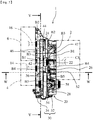
- the power transmission device 20 is provided with: a first input shaft 22 that is connected to the crank shaft CS via a flywheel FH; a first output shaft 24 that is connected to the power generator rotation shaft 16; a first gear mechanism TM1 that connects the first input shaft 22 and the first output shaft 24; and, as illustrated in FIG. 3 , with a second input shaft 26 that is connected to the motor rotation shaft 14; a differential device 28 to which wheel shafts WS are connected; a second gear mechanism TM2 that connects the second input shaft 26 and the differential device 28; and a gear case 30 that houses these members.
- crank shaft CS corresponds to an "output shaft of an internal combustion engine” of the present invention
- wheel shaft WS corresponds to a "drive shaft” of the present invention.
- upper sides of the pages of FIG. 4 and FIG. 8 are each defined as an "upper side” or “upward”
- lower sides of the pages of FIG. 4 and FIG. 8 are each defined as a “lower side” or “downward.”
- right sides of the pages of FIG. 4 and FIG. 8 are each defined as a "right side” or “rightward”
- left sides of the pages of FIG. 4 and FIG. 8 are each defined as a "left side” or “leftward.”
- the first input shaft 22 is rotatably supported on the gear case 30 via bearings B1 and B1.
- a spline protrusion is formed on the outer circumferential surface of one end side (the right side of FIG. 2 ) of the first input shaft 22, and the flywheel FH is fitted onto the spline protrusion.
- the first output shaft 24 is rotatably supported on the gear case 30 via bearings B2 and B2.
- An axial center hole is formed in the axial center of one end side (the left side of FIG. 2 ) of the first output shaft 24, and a spline recess is formed in the inner circumferential surface of the axial center hole.
- the power generator rotation shaft 16 is fitted onto the spline recess.
- the first output shaft 24 corresponds to a "coupling shaft" of the present invention.
- the first gear mechanism TM1 is constituted of a first input gear 42 that is integrally formed with the first input shaft 22, a first output gear 44 that is integrally formed with the first output shaft 24, a first idler gear 46 that meshes with the first input gear 42 and the first output gear 44, and a first idler shaft 47 that is integrally formed with the first idler gear 46.
- the first gear mechanism TM1 transmits the rotation of the crank shaft CS to the power generator rotation shaft 16.
- the first input gear 42 corresponds to a "meshing gear” of the present invention
- the first output gear 44 corresponds to a "second meshing gear” of the present invention
- the first idler gear 46 corresponds to a "scooping up gear” of the present invention.
- the first output gear 44 is smaller in diameter than the first input gear 42 and the first idler gear 46, which allows the first gear mechanism TM1 to transmit the rotation of the crank shaft CS to the power generator rotation shaft 16 with an increased rotation speed.
- the first idler shaft 47 is rotatably supported on the gear case 30 via bearings B3 and B3.
- the second input shaft 26 is rotatably supported on the gear case 30 via bearings B4 and B4.
- An axial center hole is formed in the axial center of one end side (the left side of FIG. 3 ) of the second input shaft 26, and a spline recess is formed in the inner circumferential surface of the axial center hole.
- the motor rotation shaft 14 is fitted onto the spline recess.
- the second gear mechanism TM2 is constituted of a second input gear 52 that is integrally formed with the second input shaft 26, a ring gear 54 that is fixed by bolts to the differential device 28, a second idler gear 56 that meshes with the second input gear 52, a third idler gear 58 that meshes with the ring gear 54, and a second idler shaft 59 to which the second idler gear 56 is fixed and which is integrally formed with the third idler gear 58.
- the second gear mechanism TM2 transmits the rotation of the motor rotation shaft 14 to the wheel shafts WS and WS.
- the second input gear 52 corresponds to a "motor gear” of the present invention
- the ring gear 54 corresponds to a "driving gear” of the present invention
- the second idler gear 56 corresponds to a "first intermediate gear” of the present invention
- the third idler gear 58 corresponds to a "second intermediate gear” of the present invention
- the second idler shaft 59 corresponds to a "rotation shaft of the first intermediate gear” of the present invention.
- the second idler gear 56 is larger in diameter than the second input gear 52 and the third idler gear 58, and the third idler gear 58 is smaller in diameter than the ring gear 54, which allows the second gear mechanism TM2 to transmit the rotation of the motor rotation shaft 14 to the wheel shafts WS and WS with a decreased rotation speed.
- the second idler shaft 59 is rotatably supported on the gear case 30 via bearings B5 and B5.
- the differential device 28 having the wheel shafts WS and WS spline-fitted thereto is configured to distribute and transmit power to the left and right wheel shafts WS and WS while absorbing speed differences (rotational speed differences) that occur between the left and right wheel shafts WS and WS.
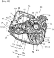
- the gear case 30 is constituted of a housing 32 and a case body 34. Fastening together a fastening flange portion 32a (see FIG. 4 ) of the housing 32 and a fastening flange portion 34a (see FIG. 6 ) of the case body 34 creates an interior space for housing the first input shaft 22, the first output shaft 24, the first gear mechanism TM1, the second input shaft 26, the differential device 28, and the second gear mechanism TM2. Lubricating oil is stored in a lower portion of the interior space.
- the gear case 30 corresponds to a "case member" of the present invention.
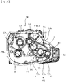
- the housing 32 has attachment holes 61, 62, 63, 64, 65, and 68 formed therein, and has a space 69 on the fastening flange portion 32a side of the attachment hole 68.
- the bearings B1, B2, B3, B4, and B5, each of which is one of the corresponding pair of bearings, are attached to the attachment holes 61, 62, 63, 64, 65, and 68.
- the attachment hole 61 is formed in substantially a central portion of the housing 32, and the attachment holes 62 and 63 are formed in that order on an oblique line extending from the attachment hole 61 toward the lower left side of FIG. 5 .
- the attachment holes 61, 62, and 63 are disposed substantially along a first virtual connecting line VCL1 (a straight line having a downward inclination to the left side of FIG. 5 ) that connects the center of the attachment hole 61 and the center of the attachment hole 63.
- VCL1 a straight line having a downward inclination to the left side of FIG. 5
- the attachment hole 64 is formed in close proximity to the upper right side of the attachment hole 61 in FIG. 5 , and the attachment holes 65 and 68 are formed in that order on an oblique line extending from the attachment hole 64 to the lower right side of FIG. 5 .
- the attachment hole 65 is disposed such that the center thereof is in a position above a second virtual connecting line VCL2 (a straight line having a downward inclination toward the right in FIG. 5 ) that connects the center of the attachment hole 64 and the center of the attachment hole 68.
- the space 69 is configured as a substantially truncated cone-shaped concave section that can house most of the differential device 28.
- the housing 32 is configured such that the first input shaft 22, the first idler shaft 47, and the first output shaft 24 (arranged in an extending direction of the first virtual connecting line VCL1) that configure the engine 2 side power transmission path, and the second input shaft 26, the second idler shaft 59, and the wheel shaft WS (arranged in an extending direction of the second virtual connecting line VCL2) that configure the motor 4 side power transmission path, are disposed in a substantial inverse V shape when viewed from the axial direction.
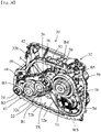
- the housing 32 is provided with a chevron-shaped rib 72, a circular arc rib 74, a vertically extending rib 76, and a covering rib 78.
- the chevron-shaped rib 72 is constituted of a first oblique rib 72a and a second oblique rib 72b, and the first oblique rib 72a and the second oblique rib 72b are connected to each other so as to form a substantial inverse V shape when viewed in the direction of the page of FIG. 5 . Furthermore, the chevron-shaped rib 72 has the same height as the fastening flange portion 32a when viewed in the direction perpendicular to the page of FIG. 5 . In other words, an upper edge face in the height direction of the chevron-shaped rib 72 and a flange face of the fastening flange portion 32a are formed flush with each other.
- the first oblique rib 72a has one end thereof connected to a lower wall portion of the housing 32 positioned directly below the attachment hole 68. Further, as illustrated in FIG. 8 , the first oblique rib 72a extends from the lower wall portion along an outer circumferential surface of the ring gear 54 and then extends in a direction tangential to the ring gear 54 (substantially parallel to the second virtual connecting line VCL2). In this example configuration, the first oblique rib 72a corresponds to a "second guiding wall" of the present invention.
- one end of the second oblique rib 72b is connected to the first oblique rib 72a, and the other end is connected to an intersection portion of a left side wall portion and the lower wall portion of the housing 32. As illustrated in FIG. 5 , one end of the second oblique rib 72b is connected to the first oblique rib 72a, and the other end is connected to an intersection portion of a left side wall portion and the lower wall portion of the housing 32. As illustrated in FIG.
- the second oblique rib 72b is constituted of a straight line portion 73a that is connected to the first oblique rib 72a, is substantially parallel to the first virtual connecting line VCL1 and extends in a direction tangential to the first idler gear 46, a first circular arc portion 73b that extends along an outer circumferential surface of the first idler gear 46, and a second circular arc portion 73c that extends along an outer circumferential surface of the first output gear 44.
- One end of the straight line portion 73a is connected to the first oblique rib 72a and the other end thereof is connected to the first circular arc portion 73b, while an end of the first circular arc portion 73b on the opposite side to the end connected to the straight line portion 73a is connected to the second circular arc portion 73c. Furthermore, an end of the second circular arc portion 73c on the opposite side to the end connected to the first circular arc portion 73b is connected to the intersection portion of the left side wall portion and the lower wall portion of the housing 32.
- the second oblique rib 72b corresponds to a "holding portion” and an "isolating wall” of the present invention. Furthermore, in this example configuration, the lower wall portion of the housing 32 corresponds to a "bottom portion of the case member" of the present invention.
- the straight line portion 73a corresponds to an "extending portion” of the present invention
- the first circular arc portion 73b corresponds to a "circular arc portion” of the present invention
- the second circular arc portion 73c corresponds to a "second circular arc portion" of the present invention.
- the circular arc rib 74 is disposed so as to partition the attachment hole 61 and the attachment hole 68 at a position between the attachment hole 61 and the straight line portion 73a.
- the circular arc rib 74 extends along the outer circumferential surface of the first input gear 42, so as to separate the first input gear 42 and the ring gear 54 at a position between the first input gear 42 and the straight line portion 73a.
- the circular arc rib 74 is configured such that one end thereof in the extending direction overlaps with the straight line portion 73a in the extending direction of the straight line portion 73a. Further, as illustrated in FIG. 8 , the circular arc rib 74 is configured such that the other end thereof in the extending direction extends to a tangential line VTL with respect to a meshing section between the ring gear 54 and the third idler gear 58.
- the circular arc rib 74 has the same height as the fastening flange portion 32a when viewed in the direction perpendicular to the page of FIG. 5 .
- an upper edge face in the height direction of the circular arc rib 74 and the flange face of the fastening flange portion 32a are formed flush with each other.
- the circular arc rib 74 corresponds to a "guiding portion" and a "guiding wall" of the present invention.
- the vertically extending rib 76 is integrally formed with a breather forming wall section 32b that defines a breather chamber, and is formed extending vertically downward from a position directly above the center of the attachment hole 61.
- the vertically extending rib 76 has the same height as the fastening flange portion 32a when viewed in the direction perpendicular to the page of FIG. 5 .
- an upper edge face in the height direction of the vertically extending rib 76 and the flange face of the fastening flange portion 32a are formed flush with each other.
- the vertically extending rib 76 corresponds to a "protruding wall portion" of the present invention.
- the breather forming wall section 32b is integrally formed with an upper wall portion of the housing 32, and has the same height as the fastening flange portion 32a when viewed in the direction perpendicular to the page of FIG. 5 . With this configuration, an upper edge face in the height direction of the breather forming wall section 32b and the flange face of the fastening flange portion 32a are formed flush with each other. As illustrated in FIG. 8 , the breather forming wall section 32b is configured such that a wall surface thereof that faces the outer circumferential surfaces of the first and second input gears 42 and 52, and the first idler gear 46 extends substantially in parallel to the first virtual connecting line VCL1. In this example configuration, the breather forming wall section 32b corresponds to an "upper interior wall surface" of the present invention.
- the covering rib 78 extends from a substantially central portion in the vertical direction of a right side wall portion of the housing 32, along the outer circumferential surface of the ring gear 54, toward the meshing section between the ring gear 54 and the third idler gear 58.
- the covering rib 78 corresponds to a "third guiding wall" of the present invention.
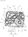
- attachment holes 81, 82, 83, 84, 85, and 88 are formed in the case body 34, in positions corresponding to the attachment holes 61, 62, 63, 64, 65, and 68 formed in the housing 32.
- the bearings B1, B2, B3, B4, and B5, each of which is the other of the corresponding pair of bearings, are attached to the attachment holes 81, 82, 83, 84, 85, and 88.
- the case body 34 is configured such that the first input shaft 22, the first idler shaft 47, and the first output shaft 24 (arranged in the extending direction of the first virtual connecting line VCL1) that configure the engine 2 side power transmission path, and the second input shaft 26, the second idler shaft 59, and the wheel shaft WS (arranged in the extending direction of the second virtual connecting line VCL2) that configure the motor 4 side power transmission path, are disposed in a substantial inverse V shape when viewed from the axial direction.
- the case body 34 is configured such that a section thereof in which the attachment hole 88 is formed is a step higher than the other sections.
- the section of the case body 34 in which the attachment holes 81, 82, 83, 84, and 85 are formed is in a concave shape.
- the section namely, a concave area CA, houses the first input gear 42, the first idler gear 46, the first output gear 44, the second input gear 52, and the second idler gear 56.
- the case body 34 is provided with an oblique rib 92, a circular arc rib 94, and a vertically extending rib 96.
- the oblique rib 92 corresponds to a "holding portion” and an "isolating wall” of the present invention
- the circular arc rib 94 corresponds to a "guiding portion” and a “guiding wall” of the present invention
- the vertically extending rib 96 corresponds to a "protruding wall portion" of the present invention.
- the oblique rib 92 is formed in a position facing the second oblique rib 72b of the chevron-shaped rib 72 formed on the housing 32, and, as illustrated in FIG. 6 and FIG. 7 , is constituted of a straight line portion 93a, a first circular arc portion 93b and a second circular arc portion 93c that respectively correspond to the straight line portion 73a, the first circular arc portion 73b and the second circular arc portion 73c of the second oblique rib 72b.
- the straight line portion 93a extends in a direction tangential to the first idler gear 46
- the first circular arc portion 93b is configured along the outer circumferential surface of the first idler gear 46
- the second circular arc portion 93c is configured along the outer circumferential surface of the first output gear 44.
- the straight line portion 93a corresponds to the "extending portion” of the present invention
- the first circular arc portion 93b corresponds to the "circular arc portion” of the present invention
- the second circular arc portion 93c corresponds to the "second circular arc portion" of the present invention.
- a notch 95 is formed in the oblique rib 92.
- the notch 95 is formed by cutting out a portion in the vicinity of a connecting portion of the straight line portion 93a and the first circular arc portion 93b, of an upper edge face in the height direction of the oblique rib 92.
- the notch 95 corresponds to a "through portion" of the present invention.
- the oblique rib 92 has the same height as the fastening flange portion 34a when viewed in the direction perpendicular to the page of FIG. 7 .
- the upper edge face in the height direction of the oblique rib 92 and a flange face of the fastening flange portion 34a are formed flush with each other.
- the circular arc rib 94 is formed in a position facing the circular arc rib 74 formed on the housing 32.
- the circular arc rib 94 extends along the outer circumferential surface of the first input gear 42, and is also configured such that one end thereof overlaps with the straight line portion 93a in the extending direction of the straight line portion 93a.
- the circular arc rib 94 has the same height as the fastening flange portion 34a when viewed in the direction perpendicular to the page of FIG. 7 .
- an upper edge face in the height direction of the circular arc rib 94 and the flange face of the fastening flange portion 34a are formed flush with each other.
- the vertically extending rib 96 is formed in a position facing the vertically extending rib 76 formed on the housing 32.
- the vertically extending rib 96 is integrally formed with a breather forming wall section 34b that defines the breather chamber, and is formed in a hanging shape vertically downward from a position directly above the center of the attachment hole 81.
- the vertically extending rib 96 has the same height as the fastening flange portion 34a when viewed in the direction perpendicular to the sheet of FIG. 7 .
- an upper edge face in the height direction of the vertically extending rib 96 and the flange face of the fastening flange portion 34a are formed flush with each other.
- the breather forming wall section 34b is integrally formed with an upper wall portion of the case body 34, and has the same height as the fastening flange portion 34a when viewed in the direction perpendicular to the sheet of FIG. 7 . With this configuration, an upper edge face in the height direction of the breather forming wall section 34b and the flange face of the fastening flange portion 34a are formed flush with each other. Similar to the breather forming wall section 32b, the breather forming wall section 34b is configured such that a wall surface thereof that faces the outer circumferential surfaces of the first and second input gears 42 and 52, and the first idler gear 46 extends substantially in parallel to the first virtual connecting line VCL1. In this example configuration, the breather forming wall section 34b corresponds to the "upper interior wall surface" of the present invention.
- the housing 32 and the case body 34 configured in this manner allows the second oblique rib 72b of the chevron-shaped rib 72 of the housing 32 and the oblique rib 92 of the case body 34, the circular arc rib 74 of the housing 32 and the circular arc rib 94 of the case body 34, the vertically extending rib 76 of the housing 32 and the vertically extending rib 96 (not illustrated in FIG. 11 ) of the case body 34, and the breather forming wall section 32b of the housing 32 and the breather forming wall section 34b of the case body 34 to come into contact with each other, respectively.
- a region S is configured in which disposed are the first input gear 42, the first idler gear 46, and the first output gear 44 that configure the engine 2 side power transmission path of the internal space of the gear case 30.
- the region S is configured as a closed space that is closed except for one side (the first input shaft 22 side, the right side of FIG. 8 ) in the arrangement direction of the first input shaft 22, the first idler shaft 47, and the first output shaft 24 (the extending direction of the first virtual connecting line VCL1), by the breather forming wall sections 32b and 34b, the second oblique rib 72b and the oblique rib 92, the circular arc ribs 74 and 94, and the vertically extending ribs 76 and 96.
- the region S is formed in an inclined U shape that extends in a direction along the first virtual connecting line VCL1 when viewed from the axial direction of each of the shafts.
- the region S is separated from a triangular-shaped space TS that is configured, in a lower portion of the internal space of the gear case 30, by the chevron-shaped rib 72 and the oblique rib 92. Note that, as illustrated in FIG. 7 , the region S communicates to the space TS via the notch 95 formed in the oblique rib 92.
- a vehicle having the power output device 1 configured in this manner installed therein is driven in modes such as: a power generation motor driving mode in which the motor 4 is driven with power generated by the power generator 6 being driven by the engine 2, a discharge motor driving mode in which the motor 4 is driven with power supplied from a secondary battery without causing the power generator 6 to generate power, and a charging mode in which the secondary battery is charged with power generated by the power generator 6 being driven by the engine 2 without driving the motor 4.
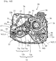
- crank shaft CS and more specifically, the first input shaft 22, is configured to rotate in the counterclockwise direction, as illustrated in FIGS. 12 to 15 .
- a state in which the ring gear 54 is rotated in the counterclockwise direction along with the motor rotation shaft 14 being rotated in the counterclockwise direction corresponds to a "rotation of in the first rotational direction the driving gear" of the present invention
- a state in which the ring gear 54 is rotated in the clockwise direction along with the motor rotation shaft 14 being rotated in the clockwise direction corresponds to a "rotation in the second rotational direction of the driving gear.”
- the power output device 1 is inclined in a state in which the first output shaft 24 side (the left sides of FIG. 14 and FIG. 15 ) is raised higher than the wheel shaft WS side (the right side of FIG. 14 and FIG. 15 ).
- This causes the oil surface OL to be inclined, and generates a state in which, although sufficient lubricating oil is present in the space 69, it cannot be said that sufficient lubricating oil is present on the second oblique rib 72b and the oblique rib 92.
- a state may be generated in which, on the second oblique rib 72b and the oblique rib 92, the lubricating oil is stored only to a degree at which the toothed portions of the first idler gear 46 are immersed on the first circular arc portions 73b and 93b.
- the lubricating oil scooped up by the first idler gear 46 is also supplied to each of the parts requiring lubrication on the engine 2 side power transmission path.
- the lubricating oil scooped up by the ring gear 54 is supplied via the circular arc ribs 74 and 94, and the straight line portions 73a and 93a of the second oblique rib 72b and the oblique rib 92.
- the lubricating oil that is scooped up by the ring gear 54 and impinges on the circular arc ribs 74 and 94 is guided onto the straight line portions 73a and 93a of the second oblique rib 72b and the oblique rib 92 by the circular arc ribs 74 and 94, and is further guided to the first circular arc portions 73b and 93b by the straight line portions 73a and 93a.
- the lubricating oil can be smoothly guided to the first circular arc portions 73b and 93b.
- the circular arc ribs 74 and 94 are configured such that one ends thereof overlap with the straight line portions 73a and 93a in the extending direction, which allows the lubricating oil to be efficiently transferred from the circular arc ribs 74 and 94 to the straight line portions 73a and 93a.
- the lubricating oil scooped up by the ring gear 54 during reverse traveling can be favorably guided to the circular arc ribs 74 and 94.
- the configuration has the covering rib 78, the lubricating oil scooped up by the ring gear 54 during forward traveling ( FIG. 14 ) can be favorably guided as far as the meshing section between the ring gear 54 and the third idler gear 58, and the amount of lubricating oil splashed toward the circular arc ribs 74 and 94 from the meshing section can be increased.
- the lubricating oil scooped up by the ring gear 54 can be even more favorably guided to the first circular arc portions 73b and 93b.
- the lubricating oil present in the space TS flows via the notch 95, along with the rotation of the first idler gear 46.
- a space between the outer circumferential surface of the first idler gear 46, and the first circular arc portions 73b and 93b has negative pressure as a result of the rotation of the first idler gear 46, which causes the lubricating oil present in the space TS to flow onto the first circular arc portions 73b and 93b via the notch 95.
- the lubricating oil stored on the first circular arc portions 73b and 93b is scooped up by the first idler gear 46, is carried to a meshing section between the first idler gear 46 and the first output gear 44, and, after lubricating that meshing section, is splashed from the meshing section toward the breather forming wall sections 32b and 34b.
- the lubricating oil that has been splashed toward the breather forming wall sections 32b and 34b and has impinged on the breather forming wall sections 32b and 34b flows as far as the vertically extending ribs 76 and 96 along the wall surfaces of the breather forming wall sections 32b and 34b and subsequently down onto the first input gear 42 along the vertically extending ribs 76 and 96.
- the lubricating oil that has flowed down onto the first input gear 42 is caused to rotate along with the rotation of the first input gear 42, is carried as far as a meshing section between the first input gear 42 and the first idler gear 46, and is splashed downward from that meshing section.
- the lubricating oil that has been splashed from the meshing section between the first input gear 42 and the first idler gear 46 impinges on the circular arc ribs 74 and 94, and subsequently flows on the circular arc ribs 74 and 94, flows down onto the straight line portions 73a and 93a, and is guided by the straight line portions 73a and 93a as far as the first circular arc portions 73b and 93b, and the second circular arc portions 73c and 93c.
- the lubricating oil that is caused to rotate along with the rotation of the first input gear 42 and is splashed in the rotational direction of the first input gear 42 can also be guided to the first circular arc portions 73b and 93b and to the second circular arc portions 73c and 93c, which can effectively prevent depletion of the lubricating oil stored on the first circular arc portions 73b and 93b and on the second circular arc portions 73c and 93c.
- the lubricating oil guided to the first circular arc portions 73b and 93b and the second circular arc portions 73c and 93c in this manner is once more scooped up by the first idler gear 46 and the first output gear 44.
- the lubricating oil scooped up by the first idler gear 46 is returned once more to the first circular arc portions 73b and 93b and the second circular arc portions 73c and 93c through the breather forming wall sections 32b and 34b, the vertically extending ribs 76 and 96, the straight line portions 73a and 93a of the second oblique rib 72b and the oblique rib 92, and the circular arc ribs 74 and 94, namely, the lubricating oil is circulated within the region S, which can favorably prevent a deterioration in the lubrication on the engine 2 side power transmission path even in the charging mode on the uphill road.
- the lubricating oil present in the space TS flows onto the first circular arc portions 73b and 93b via the notch 95, which can even more effectively prevent depletion of the lubricating oil on the first circular arc portions 73b and 93b.
- the first gear mechanism TM1 is constituted of the first input gear 42, the first output gear 44, the first idler gear 46 that meshes with both the first input gear 42 and the first output gear 44, and the first idler shaft 47 that supports the first idler gear 46, but the present invention is not limited to this configuration.
- the first gear mechanism TM1 may be constituted of only the first input gear 42 and the first output gear 44 that meshes directly with the first input gear 42, or may have a configuration in which, as with the second gear mechanism TM2, two idler gears that separately mesh with the first input gear 42 and the first output gear 44 are supported by the first idler shaft 47.
- the second oblique rib 72b and the oblique rib 92 be configured such that the lubricating oil can be scooped up by either of the first input gear 42 and the first output gear 44.
- the first gear mechanism TM1 includes the two idler gears, it is sufficient that the second oblique rib 72b and the oblique rib 92 be configured such that the lubricating oil can be scooped up by at least either of the idler gears.
- the second gear mechanism TM2 is constituted of the second input gear 52, the second idler gear 56 that meshes with the second input gear 52, the ring gear 54, the third idler gear 58 that meshes with the ring gear 54, and the second idler shaft 59 that supports the idler gears 56 and 58, but the present invention is not limited to this configuration.
- the second gear mechanism TM2 may be constituted of only the second input gear 52 and the ring gear 54 that meshes directly with the second input gear 52, or may have a configuration in which, as with the first gear mechanism TM1, an idler gear that meshes with both the second input gear 52 and the ring gear 54 is supported by the second idler shaft 59.
- the configuration is employed in which the arrangement direction of the first input shaft 22, the first idler shaft 47, and the first output shaft 24 that configure the engine 2 side power transmission path, and the arrangement direction of the second input shaft 26, the second idler shaft 59, and the wheel shaft WS that configure the motor 4 side power transmission path are disposed in a substantial inverse V shape when viewed from the axial direction, but the present invention is not limited to this configuration.
- a configuration may be employed in which the arrangement direction of the first input shaft 22, the first idler shaft 47, and the first output shaft 24, and the arrangement direction of the second input shaft 26, the second idler shaft 59, and the wheel shaft WS that configure the motor 4 side power transmission path are disposed in an inclined L shape that the wheel shaft WS is disposed furthest to the lower side when viewed from the axial direction.
- the configuration is employed in which the first oblique rib 72a and the second oblique rib 72b are connected, but as long as the lubricating oil scooped up by the ring gear 54 can be guided to the second oblique rib 72b and the oblique rib 92, a configuration may be employed in which the first oblique rib 72a and the second oblique rib 72b are not connected, or the first oblique rib 72a is not provided.
- the configuration is employed in which the first input shaft 22 is supported via the bearings B1 in the attachment holes 61 and 81 formed substantially in the center portion of the housing 32 and the case body 34, and the first output shaft 24 is supported via the bearings B3 in the attachment holes 63 and 83 formed at the intersection portion of the left side (the left side of FIG. 5 ) wall portion and the lower wall portion of the housing 32 and the intersection portion of the right side (the right side of FIG. 7 ) wall portion and the lower wall portion of the case body 34, but in contrast, a configuration may be employed in which the first input shaft 22 is supported via the bearings B1 in the attachment holes 63 and 83, and the first output shaft 24 is supported via the bearings B3 in the attachment holes 61 and 81.
- the other end in the extending direction of the circular arc rib 74 extends as far as a position where the other end is in contact with the tangential line VTL with respect to the meshing section between the ring gear 54 and the third idler gear 58, but, as illustrated in FIG. 16 , the other end in the extending direction of the circular arc rib 74 may extend as far as a position where the other end intersect the tangential line VTL.
- the circular arc rib 94 that corresponds to the circular arc rib 74 preferably has the same configuration as the circular arc rib 74.
- the circular arc ribs 74 and 94 are formed in an arc shape, but the present invention is not limited to this configuration.
- the circular arc ribs 74 and 94 may be formed in a straight line shape.
- the configuration is employed in which the notch 95 is formed in the oblique rib 92, but the notch 95 need not necessarily be formed in the oblique rib 92 and the notch 95 may be formed in the second oblique rib 72b, or need not necessarily be formed at all.
- the vertically extending rib 76 extends vertically downward from the position directly above the center of the attachment hole 61, but, as illustrated in FIG. 17 , it is sufficient that the vertically extending rib 76 be provided extending vertically downward from a position directly above a position between the center of the attachment hole 61 and the center of the attachment hole 62. Note that, in this configuration, it is sufficient that the vertically extending rib 96 also be provided in a position corresponding to the vertically extending rib 76.
- the configuration is employed in which the breather forming wall sections 32b and 34b are provided extending substantially in parallel to the first virtual connecting line VCL 1 above the first and the second input gears 42 and 52, the first idler gear 46, and the first output gear 44, but the present invention is not limited to this configuration.
- a configuration may be employed in which the breather forming wall sections 32b or 34b are not provided, and the upper wall portions of the housing 32 and the case body 34 extend substantially in parallel to the first virtual connecting line VCL 1 in the vicinity of the outer circumferential surfaces of the first and the second input gears 42 and 52, the first idler gear 46, and the first output gear 44.
- the present embodiment is an example of the embodiments of the present invention. Accordingly, the present invention is not limited to the configuration of the present embodiment.
Landscapes
- Engineering & Computer Science (AREA)
- Mechanical Engineering (AREA)
- Transportation (AREA)
- General Engineering & Computer Science (AREA)
- Chemical & Material Sciences (AREA)
- Combustion & Propulsion (AREA)
- Power Engineering (AREA)
- General Details Of Gearings (AREA)
- Hybrid Electric Vehicles (AREA)
Abstract
Description
- The present invention relates to a power transmission device configured to transmit, from an internal combustion engine to a rotation shaft of a power generator, power input via an output shaft of the internal combustion engine and to transmit, from a motor to a drive shaft, power input via a rotation shaft of the motor, and to a power output device provided with the power transmission device.
- A power transmission device is disclosed in Japanese Unexamined Patent Application Publication No.
2010-247786A - In this power transmission device, an oil pump is provided that is driven by the engine. Thereby, lubrication of each part of the device, particularly the generator drive gear train, can be favorably performed even when only the engine is driven while the driving of the motor is stopped in order to charge with electricity.
- Patent Document 1:
JP-A-2010-247786 - However, in the power transmission device disclosed in
Patent Document 1, it is required that the oil pump be separately provided and a space be secured where the oil pump is disposed; thus, there is room for improvement in terms of reducing the number of components and making a device more compact. - In light of the foregoing, an object of the present invention is to provide a technique which ensures lubrication of each part of a device while enabling a reduction in the number of parts and in the size of the device.
- A power transmission device and a power output device provided with the power transmission device of the present invention adopt the following means in order to achieve the object described above.
- According to a preferable aspect of the power transmission device according to the present invention, the power transmission device is configured to transmit, from an internal combustion engine to a rotation shaft of a power generator, power input via an output shaft of the internal combustion engine, and to transmit, from a motor to a drive shaft, power input via a rotation shaft of the motor. The power transmission device includes a first input shaft, a coupling shaft, a first gear mechanism, a second gear mechanism, and a case member. The first input shaft is disposed in parallel to the drive shaft and is connected to an output shaft of the internal combustion engine. The coupling shaft is disposed in parallel to the first input shaft and is connected to the rotation shaft of the power generator. A second input shaft is disposed in parallel to the drive shaft and is connected to the rotation shaft of the motor. The first gear mechanism connects the first input shaft and the coupling shaft. The second gear mechanism connects the second input shaft and the drive shaft. The case member is configured to store lubricating oil. Furthermore, the second gear mechanism includes a driving gear configured to be at least partially kept immersed in the lubricating oil stored in the case member. In addition, the case member includes a holding portion configured to hold lubricating oil scooped up by the driving gear. Furthermore, the first gear mechanism includes a scooping up gear configured to scoop up lubricating oil held in the holding portion. The case member is configured to guide to the holding portion at least some of the lubricating oil scooped up by the scooping up gear.
- In the present invention, "lubricating oil scooped up by the scooping up gear" preferably includes not only lubricating oil splashed as a result of the scooping up by the scooping up gear, but also lubricating oil that is scooped up by the scooping up gear and carried to a meshing section between the scooping up gear and another gear and is then splashed from the meshing section, or lubricating oil that is caused to rotate from the meshing section along with the other gear and is splashed in a rotational direction of the other gear.
- According to the present invention, the driving gear is configured to be at least partially kept immersed in the lubricating oil stored in a bottom portion of the case member, which enables, when the motor is driven, each of the parts of the device to be lubricated with the lubricating oil scooped up by the driving gear. Furthermore, the scooping up gear is configured to scoop up the lubricating oil held in the holding portion, which enables, even when only the internal combustion engine is driven, each of the parts of the device to be lubricated with the lubricating oil scooped up by the scooping up gear. Note that, in this configuration, at least some of the lubricating oil scooped up by the scooping up gear is guided to the holding portion, which can prevent depletion of the lubricating oil held in the holding portion. Thus, the lubrication with the lubricating oil scooped up by the scooping up gear can be stably ensured.
- In this configuration, irrespective of whether or not the motor is being driven, favorable lubrication can be ensured without the use of a dedicated component, such as an oil pump. As a result, the lubrication of each of the parts of the device can be ensured while achieving a reduction in the number of parts and in the size of the device.
- According to another aspect of the power transmission device according to the present invention, the case member includes a guiding portion configured to guide to the holding portion at least some of the lubricating oil scooped up by the scooping up gear.
- According to this aspect, a simple configuration in which only the guiding portion is provided on the case member enables the lubricating oil scooped up by the scooping up gear to be guided to the holding portion.
- According to yet another aspect of the power transmission device according to the present invention, the guiding portion includes a protruding wall portion protruding toward the holding portion from an upper interior wall surface of the case member. Further, the guiding portion is configured to guide to the holding portion the lubricating oil that has been scooped up by the scooping up gear and impinged on the upper interior wall surface of the case member by causing the lubricating oil to flow from the upper interior wall surface along the protruding wall portion.
- According to this aspect, a simple configuration in which only the protruding wall portion is provided enables the lubricating oil scooped up by the scooping up gear to be guided to the holding portion.
- According to yet another aspect of the power transmission device according to the present invention, the first gear mechanism includes a meshing gear that meshes with the scooping up gear. The scooping up gear and the meshing gear are configured to cause the lubricating oil splashed from a meshing section between the scooping up gear and the meshing gear to rotate in a direction toward the bottom portion of the case member. The guiding portion further includes a guiding wall configured to guide to the holding portion, of the lubricating oil splashed from the meshing section, at least some of lubricating oil moving along with the rotation of the meshing gear, and to guide to the holding portion at least some of lubricating oil scooped up by the rotation in a first rotational direction of the driving gear.
- According to this aspect, at least some of the lubricating oil splashed from the meshing section between the scooping up gear and the meshing gear and caused to rotate along with the rotation of the meshing gear and at least some of the lubricating oil scooped up by the rotation in the first rotational direction of the driving gear are guided to the holding portion, which can effectively prevent depletion of the lubricating oil held in the holding portion. In this configuration, the lubrication with the lubricating oil scooped up by the scooping up gear can be more stably ensured.
- According to yet another aspect of the power transmission device according to the present invention, when viewed from an axial direction, the first input shaft, the coupling shaft, the second input shaft, and the drive shaft are disposed such that a first virtual connecting line connecting an axial center of the first input shaft and an axial center of the coupling shaft, and a second virtual connecting line connecting an axial center of the second input shaft and an axial center of the drive shaft form a substantial inverse V shape. These members are configured such that the second input shaft is disposed closer to an apex of the substantial inverse V shape than the drive shaft. In addition, the meshing gear and the scooping up gear are disposed on the first virtual connecting line, and are configured such that the meshing gear is disposed closer to the apex of the substantial inverse V shape than the scooping up gear. The holding portion includes a circular arc portion and an extending portion, and is an isolating wall separating the scooping up gear and the bottom portion of the case member. The circular arc portion is disposed below the scooping up gear and has substantially the same curvature as the curvature of the scooping up gear. The extending portion extends substantially in parallel to the first virtual connecting line from one end of the circular arc portion to below the meshing gear. Further, when viewed from the axial direction, the guiding wall is disposed in a position corresponding to a position between the meshing gear and the extending portion and separates the meshing gear and the driving gear. Furthermore, the guiding wall is configured such that one end thereof overlaps with the extending portion in an extending direction of the extending portion.
- According to this aspect, in the power transmission device in which the first input shaft, the coupling shaft, the second input shaft, and the drive shaft are disposed such that the first virtual connecting line and the second virtual connecting line form the substantially inverse V shape when viewed from the axial direction, the effects of the present invention can be made even more evident. Note that, in this configuration, the guiding wall and the extending portion are overlapped with each other, which enables the lubricating oil that is caused to rotate along with the meshing gear and impinges on the guiding wall and the lubricating oil that is scooped up by the driving gear and impinges on the guiding wall to be efficiently guided to the holding portion. In this configuration, the depletion of the lubricating oil held in the holding portion can be more effectively prevented. As a result, the lubrication with the lubricating oil scooped up by the scooping up gear can be even more stably ensured.
- Furthermore, the holding portion has the circular arc portion, and thus the smooth scooping up of the lubricating oil by the scooping up gear can be realized. In addition, the holding portion has the extending portion, and thus the lubricating oil scooped up by the driving gear and led to the holding portion can be smoothly guided to the circular arc portion.
- According to yet another aspect of the power transmission device according to the present invention, the guiding wall is in an arc shape along the meshing gear.
- According to this aspect, the lubricating oil that is scooped up by the driving gear and impinges on the guiding wall can be guided toward the holding portion.
- According to yet another aspect of the power transmission device according to the present invention, the power transmission device further includes a second guiding wall configured to guide, to the guiding wall, the lubricating oil scooped up by the rotation in the first rotational direction of the driving gear. Further, the second guiding wall is connected to the extending portion.
- According to this aspect, the lubricating oil scooped up by the rotation in the first rotational direction of the driving gear can be efficiently guided to the guiding wall. Furthermore, the second guiding wall is connected to the extending portion, which enables the lubricating oil that has impinged on the guiding wall to be efficiently guided to the holding portion.
- According to yet another aspect of the power transmission device according to the present invention, the second gear mechanism includes a motor gear fixed to the second input shaft, the driving gear, a first intermediate gear that meshes with the motor gear, a rotation shaft of the first intermediate gear, and a second intermediate gear that is fixed to the rotation shaft of the first intermediate gear and that meshes with the driving gear. Furthermore, the second gear mechanism is configured to cause the lubricating oil scooped up by the rotation in a second rotational direction of the driving gear and splashed from a meshing section between the driving gear and the second intermediate gear to move toward the guiding wall. Further, the guiding wall is configured such that the other end thereof extends to a position intersecting a tangential line with respect to the meshing section between the driving gear and the second intermediate gear.
- According to this aspect, the lubricating oil scooped up by the rotation in the second rotational direction of the driving gear and splashed from the meshing section between the driving gear and the second intermediate gear can be effectively caused to impinge on the guiding wall. In this configuration, the amount of lubricating oil guided to the holding portion can be increased.
- According to yet another aspect of the power transmission device according to the present invention, the power transmission device further includes a third guiding wall configured to guide, to the meshing section between the driving gear and the second intermediate gear, the lubricating oil scooped up by the rotation in the second rotational direction of the driving gear.
- According to this aspect, the lubricating oil can be efficiently guided to the meshing section between the driving gear and the second intermediate gear.
- According to yet another aspect of the power transmission device according to the present invention, the protruding wall portion is disposed directly above a position between a rotational center of the scooping up gear, and a rotational center of the meshing gear. Note that the protruding wall portion can also be disposed on a second virtual connecting line.
- According to this aspect, the lubricating oil that flows down along the protruding wall portion and impinges on the scooping up gear and the meshing gear easily rotates together in the rotational direction of the scooping up gear and the meshing gear, and thus, the amount of lubricating oil splashed from the meshing section between the scooping up gear and the meshing gear can be increased, and the guiding of the lubricating oil to the holding portion via the protruding wall portion can be more effectively performed.
- According to yet another aspect of the power transmission device according to the present invention, the first gear mechanism further includes a second meshing gear that meshes with the scooping up gear. The meshing gear is fixed to one of the first input shaft and the coupling shaft. Furthermore, the second meshing gear is fixed to the other of the first input shaft and the coupling shaft. In addition, the holding portion includes a second circular arc portion disposed below the second meshing gear and extending along the second meshing gear, and separates the second meshing gear and the bottom portion of the case member. Further, the second circular arc portion is connected to the other end of the circular arc portion.
- According to this aspect, in the power transmission device configured such that the first input shaft and the rotation shaft of the power generator are connected by the first gear mechanism having a gear ratio of two stages or more, the lubrication of the first gear mechanism can be improved.
- According to yet another aspect of the power transmission device according to the present invention, the holding portion includes a through portion configured to allow, of the interior space of the case member, a space in which the scooping up gear is disposed and a space in which the bottom portion is disposed to communication with each other.
- According to this aspect, the rotation of the scooping up gear enables the vicinity of the through portion in the space of the case member in which the scooping up gear is disposed to have negative pressure lower than that of the space in which the bottom portion of the case member is disposed, which enables the lubricating oil stored in the bottom portion to be led to the holding portion via the through portion.
- According to a preferable aspect of the power output device according to the present invention, the power output device includes: an internal combustion engine; a power generator that generates power with driving of the internal combustion engine; a motor driven by the power generated by the power generator; a drive shaft through which power from the motor is output; and the power transmission device according to any of the above aspects of the present invention that connects the internal combustion engine and the power generator, and connects the motor and the drive shaft.
- According to the present invention, the configuration uses the power transmission device according to any one of the above-described aspects of the present invention. As such, the same effects as those provided by the power transmission device of the present invention are made possible, such as the effect of enabling the reduction in the number of parts and in the size of the device and ensuring the lubrication of each part of the device.
- According to the present invention, a technique that enables the reduction in the number of parts and in the size of the device and ensures the lubrication of each part of the device can be provided.
-
-
FIG. 1 is a configuration diagram illustrating an overview of a configuration of apower output device 1 according to an embodiment of the present invention. -
FIG. 2 is an explanation view illustrating a configuration of anengine 2 side power transmission path of apower transmission device 20, as seen from a direction corresponding to a cross section A-A inFIG. 8 . -
FIG. 3 is an explanation view illustrating a configuration of amotor 4 side power transmission path of thepower transmission device 20, as seen from a direction corresponding to a cross section B-B inFIG. 8 . -
FIG. 4 is a perspective view of ahousing 32. -
FIG. 5 is a front view of thehousing 32. -
FIG. 6 is a perspective view of acase body 34. -
FIG. 7 is a front view of thecase body 34. -
FIG. 8 is an explanation view of thepower transmission device 20 with thecase body 34 removed, as seen from an axial direction. -
FIG. 9 is a perspective view of thepower transmission device 20 with thecase body 34 removed. -
FIG. 10 is a perspective cross-sectional view illustrating a cross section V-V inFIG. 1 . -
FIG. 11 is a cross-sectional view illustrating a cross section W-W inFIG. 1 . -
FIG. 12 is an explanation view illustrating a state of lubricating oil when a vehicle having thepower output device 1 installed therein is traveling forward on a flat road. -
FIG. 13 is an explanation view illustrating a state of lubricating oil when the vehicle having thepower output device 1 installed therein is traveling in reverse on a flat road. -
FIG. 14 is an explanation view illustrating a state of lubricating oil when the vehicle having thepower output device 1 installed therein is traveling forward on an uphill road. -
FIG. 15 is an explanation view illustrating a state of lubricating oil when the vehicle having thepower output device 1 installed therein is traveling in reverse on an uphill road. -
FIG. 16 is a configuration diagram illustrating an overview of a configuration of thepower transmission device 20 according to a modified example. -
FIG. 17 is a configuration diagram illustrating an overview of a configuration of thehousing 32 according to a modified example. - Next, a preferred embodiment of the present invention will be described with reference to examples.
- As illustrated in
FIG. 1 , apower output device 1 according to an embodiment of the present invention is provided with apower transmission device 20 according to the embodiment of the present invention, and anengine 2, amotor 4, and apower generator 6 that are connected to thepower transmission device 20. - The
engine 2 is configured as an internal combustion engine that outputs power using a hydrocarbon-based fuel, such as gasoline or diesel fuel. Theengine 2 causes a piston (not illustrated) to reciprocate using combustion pressure generated in a combustion chamber that is not illustrated, and outputs power by converting the reciprocating motion of the piston into a rotary motion of a crank shaft CS. - The
motor 4 is provided with a rotor (not illustrated) that is fixed to amotor rotation shaft 14, and with a stator (not illustrated) that is coaxial with and surrounds the rotor. Themotor 4 is configured as both an electric motor that can provide driving force and as a three-phase alternating current synchronous generator motor that can generate power as a power generator. Themotor 4 is driven by power supplied from a battery, which is not illustrated, via an inverter (not illustrated). - The
power generator 6 is provided with a rotor (not illustrated) that is fixed to a powergenerator rotation shaft 16, and with a stator (not illustrated) that is coaxial with and surrounds the rotor. Thepower generator 6 is configured as a three-phase alternating current synchronous power generator that generates power as a result of the powergenerator rotation shaft 16 being rotated by theengine 2. The power generated by thepower generator 6 is stored in a battery (not illustrated) via an inverter that is not illustrated. - As illustrated in
FIG. 2 , thepower transmission device 20 is provided with: afirst input shaft 22 that is connected to the crank shaft CS via a flywheel FH; afirst output shaft 24 that is connected to the powergenerator rotation shaft 16; a first gear mechanism TM1 that connects thefirst input shaft 22 and thefirst output shaft 24; and, as illustrated inFIG. 3 , with asecond input shaft 26 that is connected to themotor rotation shaft 14; adifferential device 28 to which wheel shafts WS are connected; a second gear mechanism TM2 that connects thesecond input shaft 26 and thedifferential device 28; and agear case 30 that houses these members. - In this example configuration, the crank shaft CS corresponds to an "output shaft of an internal combustion engine" of the present invention, and the wheel shaft WS corresponds to a "drive shaft" of the present invention. Note that, in the present embodiment, for ease of explanation, upper sides of the pages of
FIG. 4 andFIG. 8 are each defined as an "upper side" or "upward," and lower sides of the pages ofFIG. 4 andFIG. 8 are each defined as a "lower side" or "downward." Furthermore, right sides of the pages ofFIG. 4 andFIG. 8 are each defined as a "right side" or "rightward," and left sides of the pages ofFIG. 4 andFIG. 8 are each defined as a "left side" or "leftward." - As illustrated in
FIG. 2 , thefirst input shaft 22 is rotatably supported on thegear case 30 via bearings B1 and B1. A spline protrusion is formed on the outer circumferential surface of one end side (the right side ofFIG. 2 ) of thefirst input shaft 22, and the flywheel FH is fitted onto the spline protrusion. - Furthermore, the
first output shaft 24 is rotatably supported on thegear case 30 via bearings B2 and B2. An axial center hole is formed in the axial center of one end side (the left side ofFIG. 2 ) of thefirst output shaft 24, and a spline recess is formed in the inner circumferential surface of the axial center hole. The powergenerator rotation shaft 16 is fitted onto the spline recess. In this example configuration, thefirst output shaft 24 corresponds to a "coupling shaft" of the present invention. - As illustrated in
FIG. 2 , the first gear mechanism TM1 is constituted of afirst input gear 42 that is integrally formed with thefirst input shaft 22, afirst output gear 44 that is integrally formed with thefirst output shaft 24, afirst idler gear 46 that meshes with thefirst input gear 42 and thefirst output gear 44, and afirst idler shaft 47 that is integrally formed with thefirst idler gear 46. The first gear mechanism TM1 transmits the rotation of the crank shaft CS to the powergenerator rotation shaft 16. In this example configuration, thefirst input gear 42 corresponds to a "meshing gear" of the present invention, thefirst output gear 44 corresponds to a "second meshing gear" of the present invention, and thefirst idler gear 46 corresponds to a "scooping up gear" of the present invention. - Furthermore, as illustrated in
FIG. 2 , thefirst output gear 44 is smaller in diameter than thefirst input gear 42 and thefirst idler gear 46, which allows the first gear mechanism TM1 to transmit the rotation of the crank shaft CS to the powergenerator rotation shaft 16 with an increased rotation speed. Note that thefirst idler shaft 47 is rotatably supported on thegear case 30 via bearings B3 and B3. - As illustrated in
FIG. 3 , thesecond input shaft 26 is rotatably supported on thegear case 30 via bearings B4 and B4. An axial center hole is formed in the axial center of one end side (the left side ofFIG. 3 ) of thesecond input shaft 26, and a spline recess is formed in the inner circumferential surface of the axial center hole. Themotor rotation shaft 14 is fitted onto the spline recess. - As illustrated in
FIG. 3 , the second gear mechanism TM2 is constituted of asecond input gear 52 that is integrally formed with thesecond input shaft 26, aring gear 54 that is fixed by bolts to thedifferential device 28, asecond idler gear 56 that meshes with thesecond input gear 52, athird idler gear 58 that meshes with thering gear 54, and asecond idler shaft 59 to which thesecond idler gear 56 is fixed and which is integrally formed with thethird idler gear 58. The second gear mechanism TM2 transmits the rotation of themotor rotation shaft 14 to the wheel shafts WS and WS. - In this example configuration, the
second input gear 52 corresponds to a "motor gear" of the present invention, and thering gear 54 corresponds to a "driving gear" of the present invention. Furthermore, in this example configuration, thesecond idler gear 56 corresponds to a "first intermediate gear" of the present invention, and thethird idler gear 58 corresponds to a "second intermediate gear" of the present invention. Furthermore, in this example configuration, thesecond idler shaft 59 corresponds to a "rotation shaft of the first intermediate gear" of the present invention. - In addition, as illustrated in
FIG. 3 , thesecond idler gear 56 is larger in diameter than thesecond input gear 52 and thethird idler gear 58, and thethird idler gear 58 is smaller in diameter than thering gear 54, which allows the second gear mechanism TM2 to transmit the rotation of themotor rotation shaft 14 to the wheel shafts WS and WS with a decreased rotation speed. Note that thesecond idler shaft 59 is rotatably supported on thegear case 30 via bearings B5 and B5. - As illustrated in
FIG. 3 , thedifferential device 28 having the wheel shafts WS and WS spline-fitted thereto is configured to distribute and transmit power to the left and right wheel shafts WS and WS while absorbing speed differences (rotational speed differences) that occur between the left and right wheel shafts WS and WS. - As illustrated in
FIGS. 1 to 3 , thegear case 30 is constituted of ahousing 32 and acase body 34. Fastening together afastening flange portion 32a (seeFIG. 4 ) of thehousing 32 and afastening flange portion 34a (seeFIG. 6 ) of thecase body 34 creates an interior space for housing thefirst input shaft 22, thefirst output shaft 24, the first gear mechanism TM1, thesecond input shaft 26, thedifferential device 28, and the second gear mechanism TM2. Lubricating oil is stored in a lower portion of the interior space. In this example configuration, thegear case 30 corresponds to a "case member" of the present invention. - As illustrated in
FIG. 4 andFIG. 5 , thehousing 32 has attachment holes 61, 62, 63, 64, 65, and 68 formed therein, and has aspace 69 on thefastening flange portion 32a side of theattachment hole 68. - The bearings B1, B2, B3, B4, and B5, each of which is one of the corresponding pair of bearings, are attached to the attachment holes 61, 62, 63, 64, 65, and 68. As illustrated in
FIG. 5 , theattachment hole 61 is formed in substantially a central portion of thehousing 32, and the attachment holes 62 and 63 are formed in that order on an oblique line extending from theattachment hole 61 toward the lower left side ofFIG. 5 . More specifically, the attachment holes 61, 62, and 63 are disposed substantially along a first virtual connecting line VCL1 (a straight line having a downward inclination to the left side ofFIG. 5 ) that connects the center of theattachment hole 61 and the center of theattachment hole 63. - Furthermore, as illustrated in
FIG. 5 , theattachment hole 64 is formed in close proximity to the upper right side of theattachment hole 61 inFIG. 5 , and the attachment holes 65 and 68 are formed in that order on an oblique line extending from theattachment hole 64 to the lower right side ofFIG. 5 . Theattachment hole 65 is disposed such that the center thereof is in a position above a second virtual connecting line VCL2 (a straight line having a downward inclination toward the right inFIG. 5 ) that connects the center of theattachment hole 64 and the center of theattachment hole 68. - In addition, the
space 69 is configured as a substantially truncated cone-shaped concave section that can house most of thedifferential device 28. - In this way, as illustrated in
FIG. 8 andFIG. 9 , thehousing 32 is configured such that thefirst input shaft 22, thefirst idler shaft 47, and the first output shaft 24 (arranged in an extending direction of the first virtual connecting line VCL1) that configure theengine 2 side power transmission path, and thesecond input shaft 26, thesecond idler shaft 59, and the wheel shaft WS (arranged in an extending direction of the second virtual connecting line VCL2) that configure themotor 4 side power transmission path, are disposed in a substantial inverse V shape when viewed from the axial direction. - Furthermore, as illustrated in
FIG. 5 , thehousing 32 is provided with a chevron-shapedrib 72, acircular arc rib 74, a vertically extendingrib 76, and acovering rib 78. - The chevron-shaped
rib 72 is constituted of a firstoblique rib 72a and asecond oblique rib 72b, and the firstoblique rib 72a and thesecond oblique rib 72b are connected to each other so as to form a substantial inverse V shape when viewed in the direction of the page ofFIG. 5 . Furthermore, the chevron-shapedrib 72 has the same height as thefastening flange portion 32a when viewed in the direction perpendicular to the page ofFIG. 5 . In other words, an upper edge face in the height direction of the chevron-shapedrib 72 and a flange face of thefastening flange portion 32a are formed flush with each other. - As illustrated in
FIG. 5 , the firstoblique rib 72a has one end thereof connected to a lower wall portion of thehousing 32 positioned directly below theattachment hole 68. Further, as illustrated inFIG. 8 , the firstoblique rib 72a extends from the lower wall portion along an outer circumferential surface of thering gear 54 and then extends in a direction tangential to the ring gear 54 (substantially parallel to the second virtual connecting line VCL2). In this example configuration, the firstoblique rib 72a corresponds to a "second guiding wall" of the present invention. - As illustrated in
FIG. 5 , one end of thesecond oblique rib 72b is connected to the firstoblique rib 72a, and the other end is connected to an intersection portion of a left side wall portion and the lower wall portion of thehousing 32. As illustrated inFIG. 8 , thesecond oblique rib 72b is constituted of astraight line portion 73a that is connected to the firstoblique rib 72a, is substantially parallel to the first virtual connecting line VCL1 and extends in a direction tangential to thefirst idler gear 46, a firstcircular arc portion 73b that extends along an outer circumferential surface of thefirst idler gear 46, and a secondcircular arc portion 73c that extends along an outer circumferential surface of thefirst output gear 44. - One end of the
straight line portion 73a is connected to the firstoblique rib 72a and the other end thereof is connected to the firstcircular arc portion 73b, while an end of the firstcircular arc portion 73b on the opposite side to the end connected to thestraight line portion 73a is connected to the secondcircular arc portion 73c. Furthermore, an end of the secondcircular arc portion 73c on the opposite side to the end connected to the firstcircular arc portion 73b is connected to the intersection portion of the left side wall portion and the lower wall portion of thehousing 32. - In this this example configuration, the
second oblique rib 72b corresponds to a "holding portion" and an "isolating wall" of the present invention. Furthermore, in this example configuration, the lower wall portion of thehousing 32 corresponds to a "bottom portion of the case member" of the present invention. In this this example configuration, thestraight line portion 73a corresponds to an "extending portion" of the present invention, the firstcircular arc portion 73b corresponds to a "circular arc portion" of the present invention, and the secondcircular arc portion 73c corresponds to a "second circular arc portion" of the present invention. - As illustrated in
FIG. 5 , thecircular arc rib 74 is disposed so as to partition theattachment hole 61 and theattachment hole 68 at a position between theattachment hole 61 and thestraight line portion 73a. In other words, as illustrated inFIG. 8 , thecircular arc rib 74 extends along the outer circumferential surface of thefirst input gear 42, so as to separate thefirst input gear 42 and thering gear 54 at a position between thefirst input gear 42 and thestraight line portion 73a. - Furthermore, as illustrated in
FIG. 5 andFIG. 8 , thecircular arc rib 74 is configured such that one end thereof in the extending direction overlaps with thestraight line portion 73a in the extending direction of thestraight line portion 73a. Further, as illustrated inFIG. 8 , thecircular arc rib 74 is configured such that the other end thereof in the extending direction extends to a tangential line VTL with respect to a meshing section between thering gear 54 and thethird idler gear 58. - In addition, the
circular arc rib 74 has the same height as thefastening flange portion 32a when viewed in the direction perpendicular to the page ofFIG. 5 . In other words, an upper edge face in the height direction of thecircular arc rib 74 and the flange face of thefastening flange portion 32a are formed flush with each other. In this example configuration, thecircular arc rib 74 corresponds to a "guiding portion" and a "guiding wall" of the present invention. - As illustrated in
FIG. 5 , the vertically extendingrib 76 is integrally formed with a breather formingwall section 32b that defines a breather chamber, and is formed extending vertically downward from a position directly above the center of theattachment hole 61. - Furthermore, the vertically extending
rib 76 has the same height as thefastening flange portion 32a when viewed in the direction perpendicular to the page ofFIG. 5 . In other words, an upper edge face in the height direction of the vertically extendingrib 76 and the flange face of thefastening flange portion 32a are formed flush with each other. In this example configuration, the vertically extendingrib 76 corresponds to a "protruding wall portion" of the present invention. - The breather forming
wall section 32b is integrally formed with an upper wall portion of thehousing 32, and has the same height as thefastening flange portion 32a when viewed in the direction perpendicular to the page ofFIG. 5 . With this configuration, an upper edge face in the height direction of the breather formingwall section 32b and the flange face of thefastening flange portion 32a are formed flush with each other. As illustrated inFIG. 8 , the breather formingwall section 32b is configured such that a wall surface thereof that faces the outer circumferential surfaces of the first and second input gears 42 and 52, and thefirst idler gear 46 extends substantially in parallel to the first virtual connecting line VCL1. In this example configuration, the breather formingwall section 32b corresponds to an "upper interior wall surface" of the present invention. - As illustrated in
FIG. 8 , the coveringrib 78 extends from a substantially central portion in the vertical direction of a right side wall portion of thehousing 32, along the outer circumferential surface of thering gear 54, toward the meshing section between thering gear 54 and thethird idler gear 58. In this example configuration, the coveringrib 78 corresponds to a "third guiding wall" of the present invention. - As illustrated in
FIG. 6 andFIG. 7 , attachment holes 81, 82, 83, 84, 85, and 88 are formed in thecase body 34, in positions corresponding to the attachment holes 61, 62, 63, 64, 65, and 68 formed in thehousing 32. The bearings B1, B2, B3, B4, and B5, each of which is the other of the corresponding pair of bearings, are attached to the attachment holes 81, 82, 83, 84, 85, and 88. - In other words, as with the
housing 32, thecase body 34 is configured such that thefirst input shaft 22, thefirst idler shaft 47, and the first output shaft 24 (arranged in the extending direction of the first virtual connecting line VCL1) that configure theengine 2 side power transmission path, and thesecond input shaft 26, thesecond idler shaft 59, and the wheel shaft WS (arranged in the extending direction of the second virtual connecting line VCL2) that configure themotor 4 side power transmission path, are disposed in a substantial inverse V shape when viewed from the axial direction. - Furthermore, as illustrated in
FIG. 6 , thecase body 34 is configured such that a section thereof in which theattachment hole 88 is formed is a step higher than the other sections. In other words, the section of thecase body 34 in which the attachment holes 81, 82, 83, 84, and 85 are formed is in a concave shape. The section, namely, a concave area CA, houses thefirst input gear 42, thefirst idler gear 46, thefirst output gear 44, thesecond input gear 52, and thesecond idler gear 56. - In addition, as illustrated in
FIG. 6 andFIG. 7 , thecase body 34 is provided with anoblique rib 92, acircular arc rib 94, and a vertically extendingrib 96. In this example configuration, theoblique rib 92 corresponds to a "holding portion" and an "isolating wall" of the present invention, thecircular arc rib 94 corresponds to a "guiding portion" and a "guiding wall" of the present invention, and the vertically extendingrib 96 corresponds to a "protruding wall portion" of the present invention. - The
oblique rib 92 is formed in a position facing thesecond oblique rib 72b of the chevron-shapedrib 72 formed on thehousing 32, and, as illustrated inFIG. 6 andFIG. 7 , is constituted of astraight line portion 93a, a firstcircular arc portion 93b and a secondcircular arc portion 93c that respectively correspond to thestraight line portion 73a, the firstcircular arc portion 73b and the secondcircular arc portion 73c of thesecond oblique rib 72b. - In other words, the
straight line portion 93a extends in a direction tangential to thefirst idler gear 46, the firstcircular arc portion 93b is configured along the outer circumferential surface of thefirst idler gear 46, and the secondcircular arc portion 93c is configured along the outer circumferential surface of thefirst output gear 44. In this example configuration, thestraight line portion 93a corresponds to the "extending portion" of the present invention, the firstcircular arc portion 93b corresponds to the "circular arc portion" of the present invention, and the secondcircular arc portion 93c corresponds to the "second circular arc portion" of the present invention. - Furthermore, as illustrated in
FIG. 6 andFIG. 7 , anotch 95 is formed in theoblique rib 92. Thenotch 95 is formed by cutting out a portion in the vicinity of a connecting portion of thestraight line portion 93a and the firstcircular arc portion 93b, of an upper edge face in the height direction of theoblique rib 92. In this example configuration, thenotch 95 corresponds to a "through portion" of the present invention. - Note that the
oblique rib 92 has the same height as thefastening flange portion 34a when viewed in the direction perpendicular to the page ofFIG. 7 . In other words, the upper edge face in the height direction of theoblique rib 92 and a flange face of thefastening flange portion 34a are formed flush with each other. - The
circular arc rib 94 is formed in a position facing thecircular arc rib 74 formed on thehousing 32. In other words, thecircular arc rib 94 extends along the outer circumferential surface of thefirst input gear 42, and is also configured such that one end thereof overlaps with thestraight line portion 93a in the extending direction of thestraight line portion 93a. - Note that the
circular arc rib 94 has the same height as thefastening flange portion 34a when viewed in the direction perpendicular to the page ofFIG. 7 . In other words, an upper edge face in the height direction of thecircular arc rib 94 and the flange face of thefastening flange portion 34a are formed flush with each other. - The vertically extending
rib 96 is formed in a position facing the vertically extendingrib 76 formed on thehousing 32. In other words, as illustrated inFIG. 7 , the vertically extendingrib 96 is integrally formed with a breather formingwall section 34b that defines the breather chamber, and is formed in a hanging shape vertically downward from a position directly above the center of theattachment hole 81. - Furthermore, the vertically extending
rib 96 has the same height as thefastening flange portion 34a when viewed in the direction perpendicular to the sheet ofFIG. 7 . In other words, an upper edge face in the height direction of the vertically extendingrib 96 and the flange face of thefastening flange portion 34a are formed flush with each other. - The breather forming
wall section 34b is integrally formed with an upper wall portion of thecase body 34, and has the same height as thefastening flange portion 34a when viewed in the direction perpendicular to the sheet ofFIG. 7 . With this configuration, an upper edge face in the height direction of the breather formingwall section 34b and the flange face of thefastening flange portion 34a are formed flush with each other. Similar to the breather formingwall section 32b, the breather formingwall section 34b is configured such that a wall surface thereof that faces the outer circumferential surfaces of the first and second input gears 42 and 52, and thefirst idler gear 46 extends substantially in parallel to the first virtual connecting line VCL1. In this example configuration, the breather formingwall section 34b corresponds to the "upper interior wall surface" of the present invention. - As illustrated in
FIG. 11 , fastening together, with bolts, thehousing 32 and thecase body 34 configured in this manner allows thesecond oblique rib 72b of the chevron-shapedrib 72 of thehousing 32 and theoblique rib 92 of thecase body 34, thecircular arc rib 74 of thehousing 32 and thecircular arc rib 94 of thecase body 34, the vertically extendingrib 76 of thehousing 32 and the vertically extending rib 96 (not illustrated inFIG. 11 ) of thecase body 34, and the breather formingwall section 32b of thehousing 32 and the breather formingwall section 34b of thecase body 34 to come into contact with each other, respectively. - With this configuration, a region S is configured in which disposed are the
first input gear 42, thefirst idler gear 46, and thefirst output gear 44 that configure theengine 2 side power transmission path of the internal space of thegear case 30. The region S is configured as a closed space that is closed except for one side (thefirst input shaft 22 side, the right side ofFIG. 8 ) in the arrangement direction of thefirst input shaft 22, thefirst idler shaft 47, and the first output shaft 24 (the extending direction of the first virtual connecting line VCL1), by the breather formingwall sections second oblique rib 72b and theoblique rib 92, thecircular arc ribs ribs - More specifically, the region S is formed in an inclined U shape that extends in a direction along the first virtual connecting line VCL1 when viewed from the axial direction of each of the shafts.
- Thus, as illustrated in
FIG. 8 andFIG. 10 , the region S is separated from a triangular-shaped space TS that is configured, in a lower portion of the internal space of thegear case 30, by the chevron-shapedrib 72 and theoblique rib 92. Note that, as illustrated inFIG. 7 , the region S communicates to the space TS via thenotch 95 formed in theoblique rib 92. - A vehicle having the
power output device 1 configured in this manner installed therein is driven in modes such as: a power generation motor driving mode in which themotor 4 is driven with power generated by thepower generator 6 being driven by theengine 2, a discharge motor driving mode in which themotor 4 is driven with power supplied from a secondary battery without causing thepower generator 6 to generate power, and a charging mode in which the secondary battery is charged with power generated by thepower generator 6 being driven by theengine 2 without driving themotor 4. - Next, described is movement of the lubricating oil supplied to each of the parts constituting the
power transmission device 20 during travel of the vehicle provided with thepower output device 1 configured in this manner. First, the movement of the lubricating oil when the vehicle is being driven on a flat road will be described, and then the movement of the lubricating oil when the vehicle is driven on an uphill road will be described. Note that, in the present embodiment, when the vehicle having thepower output device 1 installed therein is traveling forward, themotor rotation shaft 14 is rotated in the counterclockwise direction, as illustrated inFIG. 12 andFIG. 14 , and when the vehicle is traveling in reverse, themotor rotation shaft 14 is rotated in the clockwise direction, as illustrated inFIG. 13 andFIG. 15 . - Furthermore, the crank shaft CS, and more specifically, the
first input shaft 22, is configured to rotate in the counterclockwise direction, as illustrated inFIGS. 12 to 15 . In this example configuration, a state in which thering gear 54 is rotated in the counterclockwise direction along with themotor rotation shaft 14 being rotated in the counterclockwise direction corresponds to a "rotation of in the first rotational direction the driving gear" of the present invention, and a state in which thering gear 54 is rotated in the clockwise direction along with themotor rotation shaft 14 being rotated in the clockwise direction corresponds to a "rotation in the second rotational direction of the driving gear." - When the vehicle having the
power output device 1 installed therein is driven on a flat road, as indicated by an oil surface OL inFIG. 12 andFIG. 13 , the presence of sufficient lubricating oil in thespace 69, and on thesecond oblique rib 72b and theoblique rib 92 allows thefirst idler gear 46, thefirst output gear 44, and thering gear 54 to be sufficiently immersed in the lubricating oil. With this configuration, irrespective of the power generation motor driving mode, the discharge motor driving mode, or the charging mode, and also irrespective of forward traveling (FIG. 12 ) and reverse traveling (FIG. 13 ), due to the lubricating oil scooped up by these gears (thefirst idler gear 46, thefirst output gear 44, and the ring gear 54) immersed in the lubricating oil, sufficient lubricating oil is supplied to each of the parts requiring lubrication on theengine 2 side power transmission path and themotor 4 side power transmission path, which ensures a favorable lubrication state. - Meanwhile, when the vehicle having the
power output device 1 installed therein is driven on an uphill road, as illustrated inFIG. 14 andFIG. 15 , thepower output device 1 is inclined in a state in which thefirst output shaft 24 side (the left sides ofFIG. 14 andFIG. 15 ) is raised higher than the wheel shaft WS side (the right side ofFIG. 14 andFIG. 15 ). This causes the oil surface OL to be inclined, and generates a state in which, although sufficient lubricating oil is present in thespace 69, it cannot be said that sufficient lubricating oil is present on thesecond oblique rib 72b and theoblique rib 92. In other words, a state may be generated in which, on thesecond oblique rib 72b and theoblique rib 92, the lubricating oil is stored only to a degree at which the toothed portions of thefirst idler gear 46 are immersed on the firstcircular arc portions - When the vehicle having the
power output device 1 installed therein is driven in the power generation motor driving mode or the discharge motor driving mode in this state, since thering gear 54 is sufficiently immersed in the lubricating oil, irrespective of the forward traveling (FIG. 14 ) or the reverse traveling (FIG. 15 ), due to the lubricating oil scooped up by thering gear 54, sufficient lubricating oil is supplied to each of the parts requiring lubrication on theengine 2 side power transmission path and themotor 4 side power transmission path, which ensures a favorable lubrication state. - Note that, in the power generation motor driving mode, the lubricating oil scooped up by the
first idler gear 46 is also supplied to each of the parts requiring lubrication on theengine 2 side power transmission path. Here, on the firstcircular arc portions second oblique rib 72b and theoblique rib 92, the lubricating oil scooped up by thering gear 54 is supplied via thecircular arc ribs straight line portions second oblique rib 72b and theoblique rib 92. - Specifically, the lubricating oil that is scooped up by the
ring gear 54 and impinges on thecircular arc ribs straight line portions second oblique rib 72b and theoblique rib 92 by thecircular arc ribs circular arc portions straight line portions - Here, since the
second oblique rib 72b and theoblique rib 92 have thestraight line portions circular arc portions circular arc ribs straight line portions circular arc ribs straight line portions - Note that, since the configuration has the first
oblique rib 72a, the lubricating oil scooped up by thering gear 54 during reverse traveling (FIG. 15 ) can be favorably guided to thecircular arc ribs rib 78, the lubricating oil scooped up by thering gear 54 during forward traveling (FIG. 14 ) can be favorably guided as far as the meshing section between thering gear 54 and thethird idler gear 58, and the amount of lubricating oil splashed toward thecircular arc ribs ring gear 54 can be even more favorably guided to the firstcircular arc portions - Furthermore, onto the first
circular arc portions notch 95, along with the rotation of thefirst idler gear 46. Specifically, a space between the outer circumferential surface of thefirst idler gear 46, and the firstcircular arc portions first idler gear 46, which causes the lubricating oil present in the space TS to flow onto the firstcircular arc portions notch 95. - With this configuration, the lubrication of each of the parts to be lubricated on the
engine 2 side power transmission path can be further improved. - Meanwhile, when the vehicle having the
power output device 1 installed therein is driven in the charging mode with thepower output device 1 in the inclined state as illustrated inFIG. 14 andFIG. 15 , themotor 4 is not driven and thus the lubricating oil is not scooped up by thering gear 54, which causes the lubrication to be performed only with the lubricating oil scooped up by thefirst idler gear 46. Note that, in the charging mode, since themotor 4 is not driven, the supply of the lubricating oil to themotor 4 side power transmission path is not necessary. - In the charging mode on the uphill road, the lubricating oil stored on the first
circular arc portions first idler gear 46, is carried to a meshing section between thefirst idler gear 46 and thefirst output gear 44, and, after lubricating that meshing section, is splashed from the meshing section toward the breather formingwall sections - The lubricating oil that has been splashed toward the breather forming
wall sections wall sections ribs wall sections first input gear 42 along the vertically extendingribs - The lubricating oil that has flowed down onto the
first input gear 42 is caused to rotate along with the rotation of thefirst input gear 42, is carried as far as a meshing section between thefirst input gear 42 and thefirst idler gear 46, and is splashed downward from that meshing section. Most of the lubricating oil that has been splashed downward from that meshing section impinges on thestraight line portions second oblique rib 72b and theoblique rib 92, is guided by thestraight line portions circular arc portions second oblique rib 72b and theoblique rib 92, and is further guided by thefirst idler gear 46 as far as the secondcircular arc portions circular arc portions - Furthermore, of the lubricating oil that has been splashed from the meshing section between the
first input gear 42 and thefirst idler gear 46, the lubricating oil that is caused to rotate along with the rotation of thefirst input gear 42 and is splashed in the rotational direction of thefirst input gear 42 impinges on thecircular arc ribs circular arc ribs straight line portions straight line portions circular arc portions circular arc portions - With this configuration, the lubricating oil that is caused to rotate along with the rotation of the
first input gear 42 and is splashed in the rotational direction of thefirst input gear 42 can also be guided to the firstcircular arc portions circular arc portions circular arc portions circular arc portions - The lubricating oil guided to the first
circular arc portions circular arc portions first idler gear 46 and thefirst output gear 44. - With this configuration, the lubricating oil scooped up by the
first idler gear 46 is returned once more to the firstcircular arc portions circular arc portions wall sections ribs straight line portions second oblique rib 72b and theoblique rib 92, and thecircular arc ribs engine 2 side power transmission path even in the charging mode on the uphill road. - Note that, in a similar manner to that described above, the lubricating oil present in the space TS flows onto the first
circular arc portions notch 95, which can even more effectively prevent depletion of the lubricating oil on the firstcircular arc portions - It is needless to say that even when, in the power generation motor driving mode, the
engine 2 side power transmission path is lubricated by the lubricating oil scooped up by thefirst idler gear 46, the lubricating oil is circulated within the region S as described above. - In the present embodiment, the first gear mechanism TM1 is constituted of the
first input gear 42, thefirst output gear 44, thefirst idler gear 46 that meshes with both thefirst input gear 42 and thefirst output gear 44, and thefirst idler shaft 47 that supports thefirst idler gear 46, but the present invention is not limited to this configuration. For example, the first gear mechanism TM1 may be constituted of only thefirst input gear 42 and thefirst output gear 44 that meshes directly with thefirst input gear 42, or may have a configuration in which, as with the second gear mechanism TM2, two idler gears that separately mesh with thefirst input gear 42 and thefirst output gear 44 are supported by thefirst idler shaft 47. - In the configuration in which the first gear mechanism TM1 is constituted of only the
first input gear 42 and thefirst output gear 44 that directly meshes with thefirst input gear 42, it is sufficient that thesecond oblique rib 72b and theoblique rib 92 be configured such that the lubricating oil can be scooped up by either of thefirst input gear 42 and thefirst output gear 44. Furthermore, in the configuration in which the first gear mechanism TM1 includes the two idler gears, it is sufficient that thesecond oblique rib 72b and theoblique rib 92 be configured such that the lubricating oil can be scooped up by at least either of the idler gears. - Furthermore, the second gear mechanism TM2 is constituted of the
second input gear 52, thesecond idler gear 56 that meshes with thesecond input gear 52, thering gear 54, thethird idler gear 58 that meshes with thering gear 54, and thesecond idler shaft 59 that supports the idler gears 56 and 58, but the present invention is not limited to this configuration. For example, the second gear mechanism TM2 may be constituted of only thesecond input gear 52 and thering gear 54 that meshes directly with thesecond input gear 52, or may have a configuration in which, as with the first gear mechanism TM1, an idler gear that meshes with both thesecond input gear 52 and thering gear 54 is supported by thesecond idler shaft 59. - In the present embodiment, the configuration is employed in which the arrangement direction of the
first input shaft 22, thefirst idler shaft 47, and thefirst output shaft 24 that configure theengine 2 side power transmission path, and the arrangement direction of thesecond input shaft 26, thesecond idler shaft 59, and the wheel shaft WS that configure themotor 4 side power transmission path are disposed in a substantial inverse V shape when viewed from the axial direction, but the present invention is not limited to this configuration. For example, a configuration may be employed in which the arrangement direction of thefirst input shaft 22, thefirst idler shaft 47, and thefirst output shaft 24, and the arrangement direction of thesecond input shaft 26, thesecond idler shaft 59, and the wheel shaft WS that configure themotor 4 side power transmission path are disposed in an inclined L shape that the wheel shaft WS is disposed furthest to the lower side when viewed from the axial direction. - In the present embodiment, the configuration is employed in which the first
oblique rib 72a and thesecond oblique rib 72b are connected, but as long as the lubricating oil scooped up by thering gear 54 can be guided to thesecond oblique rib 72b and theoblique rib 92, a configuration may be employed in which the firstoblique rib 72a and thesecond oblique rib 72b are not connected, or the firstoblique rib 72a is not provided. - In the present embodiment, the configuration is employed in which the
first input shaft 22 is supported via the bearings B1 in the attachment holes 61 and 81 formed substantially in the center portion of thehousing 32 and thecase body 34, and thefirst output shaft 24 is supported via the bearings B3 in the attachment holes 63 and 83 formed at the intersection portion of the left side (the left side ofFIG. 5 ) wall portion and the lower wall portion of thehousing 32 and the intersection portion of the right side (the right side ofFIG. 7 ) wall portion and the lower wall portion of thecase body 34, but in contrast, a configuration may be employed in which thefirst input shaft 22 is supported via the bearings B1 in the attachment holes 63 and 83, and thefirst output shaft 24 is supported via the bearings B3 in the attachment holes 61 and 81. - In the present embodiment, the other end in the extending direction of the
circular arc rib 74 extends as far as a position where the other end is in contact with the tangential line VTL with respect to the meshing section between thering gear 54 and thethird idler gear 58, but, as illustrated inFIG. 16 , the other end in the extending direction of thecircular arc rib 74 may extend as far as a position where the other end intersect the tangential line VTL. Note that, in this configuration, thecircular arc rib 94 that corresponds to thecircular arc rib 74 preferably has the same configuration as thecircular arc rib 74. - According to this configuration, when the vehicle having the
power output device 1 installed therein travels forward in the power generation motor driving mode or the discharge motor mode, the lubricating oil splashed from the meshing section between thering gear 54 and thethird idler gear 58 impinges easily on thecircular arc ribs second oblique rib 72b and theoblique rib 92 via thecircular arc ribs - In the present embodiment, the
circular arc ribs circular arc ribs - In the present embodiment, the configuration is employed in which the
notch 95 is formed in theoblique rib 92, but thenotch 95 need not necessarily be formed in theoblique rib 92 and thenotch 95 may be formed in thesecond oblique rib 72b, or need not necessarily be formed at all. - In the present embodiment, the vertically extending
rib 76 extends vertically downward from the position directly above the center of theattachment hole 61, but, as illustrated inFIG. 17 , it is sufficient that the vertically extendingrib 76 be provided extending vertically downward from a position directly above a position between the center of theattachment hole 61 and the center of theattachment hole 62. Note that, in this configuration, it is sufficient that the vertically extendingrib 96 also be provided in a position corresponding to the vertically extendingrib 76. - In the present embodiment, the configuration is employed in which the breather forming
wall sections line VCL 1 above the first and the second input gears 42 and 52, thefirst idler gear 46, and thefirst output gear 44, but the present invention is not limited to this configuration. For example, a configuration may be employed in which the breather formingwall sections housing 32 and thecase body 34 extend substantially in parallel to the first virtual connectingline VCL 1 in the vicinity of the outer circumferential surfaces of the first and the second input gears 42 and 52, thefirst idler gear 46, and thefirst output gear 44. In this configuration, it is sufficient that the vertically extendingribs housing 32 and thecase body 34. - The present embodiment is an example of the embodiments of the present invention. Accordingly, the present invention is not limited to the configuration of the present embodiment.
-
- 1
- Power output device (power output device)
- 2
- Engine (internal combustion engine)
- 4
- Motor (motor)
- 6
- Power generator (power generator)
- 14
- Motor rotation shaft (rotation shaft of motor)
- 16
- Power generator rotation shaft (rotation shaft of power generator)
- 20
- Power transmission device (power transmission device)
- 22
- First input shaft (first input shaft)
- 24
- First output shaft (coupling shaft)
- 26
- Second input shaft (second input shaft)
- 28
- Differential device
- 30
- Gear case (case member)
- 32
- Housing
- 32a
- Fastening flange portion
- 32b
- Breather forming wall section (upper interior wall surface)
- 34
- Case body
- 34a
- Fastening flange portion
- 34b
- Breather forming wall section (upper interior wall surface)
- 42
- First input gear (meshing gear)
- 44
- First output gear (second meshing gear)
- 46
- First idler gear (scooping up gear)
- 47
- First idler shaft
- 52
- Second input gear (motor gear)
- 54
- Ring gear (driving gear)
- 56
- Second idler gear (first intermediate gear)
- 58
- Third idler gear (second intermediate gear)
- 59
- Second idler shaft (rotation shaft of first intermediate gear)
- 61
- Attachment hole
- 62
- Attachment hole
- 63
- Attachment hole
- 64
- Attachment hole
- 65
- Attachment hole
- 68
- Attachment hole
- 69
- Space
- 72
- Chevron-shaped rib
- 72a
- First oblique rib (second guiding wall)
- 72b
- Second oblique rib (holding portion, isolating wall)
- 73a
- Straight line portion (extending portion)
- 73b
- First circular arc portion (circular arc portion)
- 73c
- Second circular arc portion (second circular arc portion)
- 74
- Circular arc rib (guiding portion, guiding wall)
- 76
- Vertically extending rib (protruding wall portion)
- 78
- Covering rib (third guiding wall)
- 81
- Attachment hole
- 82
- Attachment hole
- 83
- Attachment hole
- 84
- Attachment hole
- 85
- Attachment hole
- 88
- Attachment hole
- 92
- Oblique rib (holding portion, isolating wall)
- 93a
- Straight line portion (extending portion)
- 93b
- First circular arc portion (circular arc portion)
- 93c
- Second circular arc portion (second circular arc portion)
- 94
- Circular arc rib (guiding portion, guiding wall)
- 95
- Notch (through portion)
- 96
- Vertically extending rib (protruding wall portion)
- CS
- Crank shaft (output shaft of internal combustion engine)
- FH
- Flywheel
- TM1
- First gear mechanism (first gear mechanism)
- TM2
- Second gear mechanism (second gear mechanism)
- B1
- Bearing
- B2
- Bearing
- B3
- Bearing
- B4
- Bearing
- B5
- Bearing
- WS
- Wheel shaft (drive shaft)
- VCL1
- First virtual connecting line (first virtual connecting line)
- VCL2
- Second virtual connecting line (second virtual connecting line)
- CA
- Concave area
- S
- Region
- TS
- Space
Claims (14)
- A power transmission device configured to transmit, from an internal combustion engine to a rotation shaft of a power generator, power input via an output shaft of the internal combustion engine, and to transmit, from a motor to a drive shaft, power input via a rotation shaft of the motor, the power transmission device comprising:a first input shaft disposed in parallel to the drive shaft and connected to the output shaft of the internal combustion engine;a coupling shaft disposed in parallel to the first input shaft and connected to the rotation shaft of the power generator;a second input shaft disposed in parallel to the drive shaft and connected to the rotation shaft of the motor;a first gear mechanism connecting the first input shaft and the coupling shaft;a second gear mechanism connecting the second input shaft and the drive shaft; anda case member configured to store lubricating oil,wherein:the second gear mechanism includes a driving gear configured to be at least partially kept immersed in the lubricating oil stored in the case member;the case member includes a holding portion configured to hold lubricating oil scooped up by the driving gear;the first gear mechanism includes a scooping up gear configured to scoop up lubricating oil held in the holding portion; andthe case member is configured to guide to the holding portion at least some of the lubricating oil scooped by the scooping up gear.
- The power transmission device according to claim 1, wherein:the case member includes a guiding portion configured to guide to the holding portion at least some of the lubricating oil scooped up by the scooping up gear.
- The power transmission device according to claim 2, wherein:the guiding portion includes a protruding wall portion protruding toward the holding portion from an upper interior wall surface of the case member; andthe guiding portion is configured to guide to the holding portion the lubricating oil that has been scooped up by the scooping up gear and impinged on the upper interior wall surface by causing the lubricating oil to flow from the upper interior wall surface along the protruding wall portion.
- The power transmission device according to claim 2 or 3, wherein:the first gear mechanism includes a meshing gear that meshes with the scooping up gear;the scooping up gear and the meshing gear are configured to cause the lubricating oil splashed from a meshing section between the scooping up gear and the meshing gear to rotate in a direction toward a bottom portion of the case member; andthe guiding portion further includes a guiding wall configured to guide to the holding portion, of the lubricating oil splashed from the meshing section, at least some of lubricating oil caused to rotate along with the rotation of the meshing gear, and to guide to the holding portion at least some of lubricating oil scooped up by the rotation in a first rotational direction of the driving gear.
- The power transmission device according to claim 4, wherein:when viewed from an axial direction, the first input shaft, the coupling shaft, the second input shaft, and the driving shaft are disposed such that a first virtual connecting line connecting an axial center of the first input shaft and an axial center of the coupling shaft, and a second virtual connecting line connecting an axial center of the second input shaft and an axial center of the drive shaft form a substantial inverse V shape, and are configured such that the second input shaft is disposed closer to an apex of the substantial inverse V shape than the drive shaft;the meshing gear and the scooping up gear are disposed on the first virtual connecting line and are configured such that the meshing gear is disposed closer to the apex of the substantial inverse V shape than the scooping up gear;the holding portion includes a circular arc portion disposed below the scooping up gear and has substantially the same curvature as curvature of the scooping up gear, and an extending portion extending substantially in parallel to the first virtual connecting line from one end of the circular arc portion to below the meshing gear, and is an isolating wall separating the scooping up gear and the bottom portion of the case member; andwhen viewed from the axial direction, the guiding wall is disposed in a position corresponding to a position between the meshing gear and the extending portion, and separates the meshing gear and the driving gear, and is configured such that one end thereof overlaps with the extending portion in an extending direction of the extending portion.
- The power transmission device according to claim 5, wherein:the guiding wall is in an arc shape along the meshing gear.
- The power transmission device according to claim 5 or 6, further comprising:a second guiding wall configured to guide, to the guiding wall, the lubricating oil scooped up by the rotation in the first rotational direction of the driving gear,wherein:the second guiding wall is connected to the extending portion.
- The power transmission device according to any one of claims 5 to 7, wherein:the second gear mechanism includes a motor gear fixed to the second input shaft, the driving gear, a first intermediate gear that meshes with the motor gear, a rotation shaft of the first intermediate gear, and a second intermediate gear fixed to the rotation shaft of the first intermediate gear and that meshes with the driving gear, and is configured to cause lubricating oil scooped up by rotation in a second rotational direction of the driving gear and splashed from a meshing section between the driving gear and the second intermediate gear to move toward the guiding wall; andthe guiding wall is configured such that the other end thereof extends to a position intersecting a tangential line with respect to the meshing section between the driving gear and the second intermediate gear.
- The power transmission device according to claim 8, further comprising:a third guiding wall configured to guide, to the meshing section between the driving gear and the second intermediate gear, the lubricating oil scooped up by the rotation in the second rotational direction of the driving gear.
- The power transmission device according to any one of claims 5 to 9, wherein:the protruding wall portion is disposed directly above a position between a rotational center of the scooping up gear and a rotational center of the meshing gear.
- The power transmission device according to claim 10, wherein:the protruding wall portion is disposed directly above the rotational center of the meshing gear.
- The power transmission device according to any one of claims 5 to 11, wherein:the first gear mechanism further includes a second meshing gear that meshes with the scooping up gear;the meshing gear is fixed to one of the first input shaft and the coupling shaft;the second meshing gear is fixed to the other of the first input shaft and the coupling shaft;the holding portion includes a second circular arc portion disposed below the second meshing gear and extending along the second meshing gear, and separates the second meshing gear and the bottom portion of the case member; andthe second circular arc portion is connected to the other end of the circular arc portion.
- The power transmission device according to any one of claims 5 to 11, wherein
the circular arc portion includes a through portion configured to allow, of an interior space of the case member, a space in which the scooping up gear is disposed and a space in which the bottom portion is disposed to communicate with each other. - A power output device comprising:an internal combustion engine;a power generator that generates power with driving of the internal combustion engine;a motor driven by the power generated by the power generator;a drive shaft through which power from the motor is output; andthe power transmission device according to any one of claims 1 to 13 connecting the internal combustion engine and the power generator, and connecting the motor and the drive shaft.
Applications Claiming Priority (2)
| Application Number | Priority Date | Filing Date | Title |
|---|---|---|---|
| JP2015098619 | 2015-05-13 | ||
| PCT/JP2016/059898 WO2016181713A1 (en) | 2015-05-13 | 2016-03-28 | Power transmitting device and power outputting device with same |
Publications (3)
| Publication Number | Publication Date |
|---|---|
| EP3296133A1 true EP3296133A1 (en) | 2018-03-21 |
| EP3296133A4 EP3296133A4 (en) | 2019-02-06 |
| EP3296133B1 EP3296133B1 (en) | 2021-07-14 |
Family
ID=57247951
Family Applications (1)
| Application Number | Title | Priority Date | Filing Date |
|---|---|---|---|
| EP16792438.0A Active EP3296133B1 (en) | 2015-05-13 | 2016-03-28 | Power transmitting device and power outputting device with same |
Country Status (4)
| Country | Link |
|---|---|
| EP (1) | EP3296133B1 (en) |
| JP (1) | JP6595587B2 (en) |
| CN (1) | CN107531141B (en) |
| WO (1) | WO2016181713A1 (en) |
Families Citing this family (4)
| Publication number | Priority date | Publication date | Assignee | Title |
|---|---|---|---|---|
| JP7017390B2 (en) * | 2017-12-08 | 2022-02-08 | ジーケーエヌ オートモーティブ リミテッド | Power transmission device |
| DE102019102078B3 (en) * | 2019-01-28 | 2020-06-04 | Gkn Automotive Limited | Gear arrangement |
| JP7298257B2 (en) * | 2019-04-11 | 2023-06-27 | ニデック株式会社 | drive |
| JP6791464B1 (en) * | 2019-11-18 | 2020-11-25 | 三菱電機株式会社 | Speed reducer and industrial robot |
Family Cites Families (11)
| Publication number | Priority date | Publication date | Assignee | Title |
|---|---|---|---|---|
| JP4399116B2 (en) * | 1998-12-01 | 2010-01-13 | 日立オートモティブシステムズ株式会社 | Driving device and vehicle |
| JP2005106266A (en) * | 2003-09-11 | 2005-04-21 | Honda Motor Co Ltd | Driving device for vehicles |
| JP4867491B2 (en) * | 2005-07-28 | 2012-02-01 | トヨタ自動車株式会社 | Driving device and automobile equipped with the same |
| JP2009118558A (en) * | 2007-11-02 | 2009-05-28 | Toyota Motor Corp | Driving device |
| CA2721382C (en) * | 2008-04-14 | 2013-04-09 | Honda Motor Co., Ltd. | Driving apparatus for hybrid vehicle |
| JP4743241B2 (en) * | 2008-08-29 | 2011-08-10 | トヨタ自動車株式会社 | Power transmission device |
| JP5163486B2 (en) * | 2008-12-25 | 2013-03-13 | トヨタ自動車株式会社 | Power transmission device |
| JP5443914B2 (en) * | 2009-09-15 | 2014-03-19 | アイシン・エーアイ株式会社 | transmission |
| US8931596B2 (en) * | 2010-02-04 | 2015-01-13 | Toyota Jidosha Kabushiki Kaisha | Lubricant oil supplying apparatus |
| EP2700849B1 (en) * | 2011-04-20 | 2016-05-11 | Toyota Jidosha Kabushiki Kaisha | Lubricating oil supply device for power transmission device |
| CN105793083B (en) * | 2013-12-26 | 2018-04-03 | 爱信艾达株式会社 | Vehicle driving apparatus |
-
2016
- 2016-03-28 JP JP2017517639A patent/JP6595587B2/en active Active
- 2016-03-28 CN CN201680024280.7A patent/CN107531141B/en active Active
- 2016-03-28 WO PCT/JP2016/059898 patent/WO2016181713A1/en unknown
- 2016-03-28 EP EP16792438.0A patent/EP3296133B1/en active Active
Also Published As
| Publication number | Publication date |
|---|---|
| JP6595587B2 (en) | 2019-10-23 |
| CN107531141B (en) | 2019-11-19 |
| EP3296133B1 (en) | 2021-07-14 |
| CN107531141A (en) | 2018-01-02 |
| WO2016181713A1 (en) | 2016-11-17 |
| EP3296133A4 (en) | 2019-02-06 |
| JPWO2016181713A1 (en) | 2018-03-15 |
Similar Documents
| Publication | Publication Date | Title |
|---|---|---|
| EP2700849A1 (en) | Lubricating oil supply device for power transmission device | |
| CN112449739B (en) | Electric driver with cooling function | |
| EP3296133B1 (en) | Power transmitting device and power outputting device with same | |
| JP4770947B2 (en) | Vehicle power transmission device | |
| JP6551389B2 (en) | Hybrid vehicle lubrication structure | |
| JP5790630B2 (en) | Lubricating oil supply structure | |
| JP5163486B2 (en) | Power transmission device | |
| EP3560743A1 (en) | Vehicle drive device | |
| CN105705835A (en) | Drive transmission device for vehicle | |
| JP2010139052A (en) | Power transmission device | |
| CN107407396B (en) | Power transmission device and power output device provided with same | |
| US9945472B2 (en) | Lubricating structure for transmission | |
| JP2009257518A (en) | Lubrication structure of power transmission device | |
| WO2019244564A1 (en) | Vehicle drive device | |
| JP5454464B2 (en) | In-wheel motor drive device | |
| WO2020110417A1 (en) | Vehicle drive device | |
| CN113669435A (en) | Hybrid drive system's lubricated cooling system and vehicle | |
| JP5527240B2 (en) | Lubricator for power transmission system | |
| JP7133537B2 (en) | transaxle | |
| JP2022103151A (en) | Vehicle drive device | |
| JP5012686B2 (en) | Oil supply device | |
| JP2017082865A (en) | Lubricant supply structure of power transmission device | |
| JP7004081B2 (en) | Hybrid vehicle | |
| KR101280761B1 (en) | Device for driving rear wheel of hybrid vehicle using longitudinal motor | |
| JP2012072877A (en) | Oil supply device |
Legal Events
| Date | Code | Title | Description |
|---|---|---|---|
| STAA | Information on the status of an ep patent application or granted ep patent |
Free format text: STATUS: THE INTERNATIONAL PUBLICATION HAS BEEN MADE |
|
| PUAI | Public reference made under article 153(3) epc to a published international application that has entered the european phase |
Free format text: ORIGINAL CODE: 0009012 |
|
| STAA | Information on the status of an ep patent application or granted ep patent |
Free format text: STATUS: REQUEST FOR EXAMINATION WAS MADE |
|
| 17P | Request for examination filed |
Effective date: 20171020 |
|
| AK | Designated contracting states |
Kind code of ref document: A1 Designated state(s): AL AT BE BG CH CY CZ DE DK EE ES FI FR GB GR HR HU IE IS IT LI LT LU LV MC MK MT NL NO PL PT RO RS SE SI SK SM TR |
|
| AX | Request for extension of the european patent |
Extension state: BA ME |
|
| DAV | Request for validation of the european patent (deleted) | ||
| DAX | Request for extension of the european patent (deleted) | ||
| A4 | Supplementary search report drawn up and despatched |
Effective date: 20190109 |
|
| RIC1 | Information provided on ipc code assigned before grant |
Ipc: F16H 1/06 20060101ALI20161122BHEP Ipc: B60L 11/14 20060101ALI20161122BHEP Ipc: B60K 6/405 20071001AFI20161122BHEP Ipc: B60K 6/40 20071001ALI20161122BHEP Ipc: F16H 57/04 20100101ALI20161122BHEP |
|
| STAA | Information on the status of an ep patent application or granted ep patent |
Free format text: STATUS: EXAMINATION IS IN PROGRESS |
|
| 17Q | First examination report despatched |
Effective date: 20200330 |
|
| STAA | Information on the status of an ep patent application or granted ep patent |
Free format text: STATUS: EXAMINATION IS IN PROGRESS |
|
| RIC1 | Information provided on ipc code assigned before grant |
Ipc: B60K 7/00 20060101ALI20201019BHEP Ipc: B60K 6/46 20071001ALI20201019BHEP Ipc: F16H 1/06 20060101ALI20201019BHEP Ipc: F16H 57/04 20100101ALI20201019BHEP Ipc: B60K 6/405 20071001AFI20201019BHEP Ipc: B60K 6/40 20071001ALI20201019BHEP Ipc: B60L 50/16 20190101ALI20201019BHEP |
|
| GRAP | Despatch of communication of intention to grant a patent |
Free format text: ORIGINAL CODE: EPIDOSNIGR1 |
|
| STAA | Information on the status of an ep patent application or granted ep patent |
Free format text: STATUS: GRANT OF PATENT IS INTENDED |
|
| INTG | Intention to grant announced |
Effective date: 20201218 |
|
| RIN1 | Information on inventor provided before grant (corrected) |
Inventor name: AOYAMA, HIDEKI Inventor name: NAKADERA, HIROYUKI Inventor name: KONDO, HIROMASA Inventor name: SATO, KAZUHIKO Inventor name: SATO, MOTOHIKO Inventor name: KOKUBO, AKIRA Inventor name: NAKASHIMA, TAKAYUKI |
|
| GRAJ | Information related to disapproval of communication of intention to grant by the applicant or resumption of examination proceedings by the epo deleted |
Free format text: ORIGINAL CODE: EPIDOSDIGR1 |
|
| STAA | Information on the status of an ep patent application or granted ep patent |
Free format text: STATUS: EXAMINATION IS IN PROGRESS |
|
| INTC | Intention to grant announced (deleted) | ||
| GRAP | Despatch of communication of intention to grant a patent |
Free format text: ORIGINAL CODE: EPIDOSNIGR1 |
|
| STAA | Information on the status of an ep patent application or granted ep patent |
Free format text: STATUS: GRANT OF PATENT IS INTENDED |
|
| INTG | Intention to grant announced |
Effective date: 20210421 |
|
| GRAS | Grant fee paid |
Free format text: ORIGINAL CODE: EPIDOSNIGR3 |
|
| GRAA | (expected) grant |
Free format text: ORIGINAL CODE: 0009210 |
|
| STAA | Information on the status of an ep patent application or granted ep patent |
Free format text: STATUS: THE PATENT HAS BEEN GRANTED |
|
| AK | Designated contracting states |
Kind code of ref document: B1 Designated state(s): AL AT BE BG CH CY CZ DE DK EE ES FI FR GB GR HR HU IE IS IT LI LT LU LV MC MK MT NL NO PL PT RO RS SE SI SK SM TR |
|
| REG | Reference to a national code |
Ref country code: GB Ref legal event code: FG4D |
|
| REG | Reference to a national code |
Ref country code: IE Ref legal event code: FG4D |
|
| REG | Reference to a national code |
Ref country code: DE Ref legal event code: R096 Ref document number: 602016060657 Country of ref document: DE |
|
| REG | Reference to a national code |
Ref country code: AT Ref legal event code: REF Ref document number: 1410366 Country of ref document: AT Kind code of ref document: T Effective date: 20210815 |
|
| REG | Reference to a national code |
Ref country code: LT Ref legal event code: MG9D |
|
| REG | Reference to a national code |
Ref country code: NL Ref legal event code: MP Effective date: 20210714 |
|
| REG | Reference to a national code |
Ref country code: AT Ref legal event code: MK05 Ref document number: 1410366 Country of ref document: AT Kind code of ref document: T Effective date: 20210714 |
|
| PG25 | Lapsed in a contracting state [announced via postgrant information from national office to epo] |
Ref country code: RS Free format text: LAPSE BECAUSE OF FAILURE TO SUBMIT A TRANSLATION OF THE DESCRIPTION OR TO PAY THE FEE WITHIN THE PRESCRIBED TIME-LIMIT Effective date: 20210714 Ref country code: SE Free format text: LAPSE BECAUSE OF FAILURE TO SUBMIT A TRANSLATION OF THE DESCRIPTION OR TO PAY THE FEE WITHIN THE PRESCRIBED TIME-LIMIT Effective date: 20210714 Ref country code: NL Free format text: LAPSE BECAUSE OF FAILURE TO SUBMIT A TRANSLATION OF THE DESCRIPTION OR TO PAY THE FEE WITHIN THE PRESCRIBED TIME-LIMIT Effective date: 20210714 Ref country code: NO Free format text: LAPSE BECAUSE OF FAILURE TO SUBMIT A TRANSLATION OF THE DESCRIPTION OR TO PAY THE FEE WITHIN THE PRESCRIBED TIME-LIMIT Effective date: 20211014 Ref country code: PT Free format text: LAPSE BECAUSE OF FAILURE TO SUBMIT A TRANSLATION OF THE DESCRIPTION OR TO PAY THE FEE WITHIN THE PRESCRIBED TIME-LIMIT Effective date: 20211115 Ref country code: FI Free format text: LAPSE BECAUSE OF FAILURE TO SUBMIT A TRANSLATION OF THE DESCRIPTION OR TO PAY THE FEE WITHIN THE PRESCRIBED TIME-LIMIT Effective date: 20210714 Ref country code: ES Free format text: LAPSE BECAUSE OF FAILURE TO SUBMIT A TRANSLATION OF THE DESCRIPTION OR TO PAY THE FEE WITHIN THE PRESCRIBED TIME-LIMIT Effective date: 20210714 Ref country code: HR Free format text: LAPSE BECAUSE OF FAILURE TO SUBMIT A TRANSLATION OF THE DESCRIPTION OR TO PAY THE FEE WITHIN THE PRESCRIBED TIME-LIMIT Effective date: 20210714 Ref country code: LT Free format text: LAPSE BECAUSE OF FAILURE TO SUBMIT A TRANSLATION OF THE DESCRIPTION OR TO PAY THE FEE WITHIN THE PRESCRIBED TIME-LIMIT Effective date: 20210714 Ref country code: AT Free format text: LAPSE BECAUSE OF FAILURE TO SUBMIT A TRANSLATION OF THE DESCRIPTION OR TO PAY THE FEE WITHIN THE PRESCRIBED TIME-LIMIT Effective date: 20210714 Ref country code: BG Free format text: LAPSE BECAUSE OF FAILURE TO SUBMIT A TRANSLATION OF THE DESCRIPTION OR TO PAY THE FEE WITHIN THE PRESCRIBED TIME-LIMIT Effective date: 20211014 |
|
| PG25 | Lapsed in a contracting state [announced via postgrant information from national office to epo] |
Ref country code: PL Free format text: LAPSE BECAUSE OF FAILURE TO SUBMIT A TRANSLATION OF THE DESCRIPTION OR TO PAY THE FEE WITHIN THE PRESCRIBED TIME-LIMIT Effective date: 20210714 Ref country code: LV Free format text: LAPSE BECAUSE OF FAILURE TO SUBMIT A TRANSLATION OF THE DESCRIPTION OR TO PAY THE FEE WITHIN THE PRESCRIBED TIME-LIMIT Effective date: 20210714 Ref country code: GR Free format text: LAPSE BECAUSE OF FAILURE TO SUBMIT A TRANSLATION OF THE DESCRIPTION OR TO PAY THE FEE WITHIN THE PRESCRIBED TIME-LIMIT Effective date: 20211015 |
|
| REG | Reference to a national code |
Ref country code: DE Ref legal event code: R097 Ref document number: 602016060657 Country of ref document: DE |
|
| PG25 | Lapsed in a contracting state [announced via postgrant information from national office to epo] |
Ref country code: DK Free format text: LAPSE BECAUSE OF FAILURE TO SUBMIT A TRANSLATION OF THE DESCRIPTION OR TO PAY THE FEE WITHIN THE PRESCRIBED TIME-LIMIT Effective date: 20210714 |
|
| PLBE | No opposition filed within time limit |
Free format text: ORIGINAL CODE: 0009261 |
|
| STAA | Information on the status of an ep patent application or granted ep patent |
Free format text: STATUS: NO OPPOSITION FILED WITHIN TIME LIMIT |
|
| PG25 | Lapsed in a contracting state [announced via postgrant information from national office to epo] |
Ref country code: SM Free format text: LAPSE BECAUSE OF FAILURE TO SUBMIT A TRANSLATION OF THE DESCRIPTION OR TO PAY THE FEE WITHIN THE PRESCRIBED TIME-LIMIT Effective date: 20210714 Ref country code: SK Free format text: LAPSE BECAUSE OF FAILURE TO SUBMIT A TRANSLATION OF THE DESCRIPTION OR TO PAY THE FEE WITHIN THE PRESCRIBED TIME-LIMIT Effective date: 20210714 Ref country code: RO Free format text: LAPSE BECAUSE OF FAILURE TO SUBMIT A TRANSLATION OF THE DESCRIPTION OR TO PAY THE FEE WITHIN THE PRESCRIBED TIME-LIMIT Effective date: 20210714 Ref country code: EE Free format text: LAPSE BECAUSE OF FAILURE TO SUBMIT A TRANSLATION OF THE DESCRIPTION OR TO PAY THE FEE WITHIN THE PRESCRIBED TIME-LIMIT Effective date: 20210714 Ref country code: CZ Free format text: LAPSE BECAUSE OF FAILURE TO SUBMIT A TRANSLATION OF THE DESCRIPTION OR TO PAY THE FEE WITHIN THE PRESCRIBED TIME-LIMIT Effective date: 20210714 Ref country code: AL Free format text: LAPSE BECAUSE OF FAILURE TO SUBMIT A TRANSLATION OF THE DESCRIPTION OR TO PAY THE FEE WITHIN THE PRESCRIBED TIME-LIMIT Effective date: 20210714 |
|
| 26N | No opposition filed |
Effective date: 20220419 |
|
| REG | Reference to a national code |
Ref country code: DE Ref legal event code: R081 Ref document number: 602016060657 Country of ref document: DE Owner name: NISSAN MOTOR CO., LTD., YOKOHAMA-SHI, JP Free format text: FORMER OWNER: AICHI MACHINE INDUSTRY CO., LTD., NAGOYA-SHI, AICHI, JP Ref country code: DE Ref legal event code: R082 Ref document number: 602016060657 Country of ref document: DE Representative=s name: GRUENECKER PATENT- UND RECHTSANWAELTE PARTG MB, DE |
|
| PG25 | Lapsed in a contracting state [announced via postgrant information from national office to epo] |
Ref country code: IT Free format text: LAPSE BECAUSE OF FAILURE TO SUBMIT A TRANSLATION OF THE DESCRIPTION OR TO PAY THE FEE WITHIN THE PRESCRIBED TIME-LIMIT Effective date: 20210714 |
|
| REG | Reference to a national code |
Ref country code: GB Ref legal event code: 732E Free format text: REGISTERED BETWEEN 20220721 AND 20220727 |
|
| PG25 | Lapsed in a contracting state [announced via postgrant information from national office to epo] |
Ref country code: MC Free format text: LAPSE BECAUSE OF FAILURE TO SUBMIT A TRANSLATION OF THE DESCRIPTION OR TO PAY THE FEE WITHIN THE PRESCRIBED TIME-LIMIT Effective date: 20210714 |
|
| REG | Reference to a national code |
Ref country code: CH Ref legal event code: PL |
|
| REG | Reference to a national code |
Ref country code: BE Ref legal event code: MM Effective date: 20220331 |
|
| PG25 | Lapsed in a contracting state [announced via postgrant information from national office to epo] |
Ref country code: LU Free format text: LAPSE BECAUSE OF NON-PAYMENT OF DUE FEES Effective date: 20220328 Ref country code: LI Free format text: LAPSE BECAUSE OF NON-PAYMENT OF DUE FEES Effective date: 20220331 Ref country code: IE Free format text: LAPSE BECAUSE OF NON-PAYMENT OF DUE FEES Effective date: 20220328 Ref country code: CH Free format text: LAPSE BECAUSE OF NON-PAYMENT OF DUE FEES Effective date: 20220331 |
|
| PG25 | Lapsed in a contracting state [announced via postgrant information from national office to epo] |
Ref country code: BE Free format text: LAPSE BECAUSE OF NON-PAYMENT OF DUE FEES Effective date: 20220331 |
|
| PGFP | Annual fee paid to national office [announced via postgrant information from national office to epo] |
Ref country code: FR Payment date: 20230222 Year of fee payment: 8 |
|
| PG25 | Lapsed in a contracting state [announced via postgrant information from national office to epo] |
Ref country code: HU Free format text: LAPSE BECAUSE OF FAILURE TO SUBMIT A TRANSLATION OF THE DESCRIPTION OR TO PAY THE FEE WITHIN THE PRESCRIBED TIME-LIMIT; INVALID AB INITIO Effective date: 20160328 |
|
| PG25 | Lapsed in a contracting state [announced via postgrant information from national office to epo] |
Ref country code: MK Free format text: LAPSE BECAUSE OF FAILURE TO SUBMIT A TRANSLATION OF THE DESCRIPTION OR TO PAY THE FEE WITHIN THE PRESCRIBED TIME-LIMIT Effective date: 20210714 Ref country code: CY Free format text: LAPSE BECAUSE OF FAILURE TO SUBMIT A TRANSLATION OF THE DESCRIPTION OR TO PAY THE FEE WITHIN THE PRESCRIBED TIME-LIMIT Effective date: 20210714 |
|
| PGFP | Annual fee paid to national office [announced via postgrant information from national office to epo] |
Ref country code: DE Payment date: 20240220 Year of fee payment: 9 Ref country code: GB Payment date: 20240220 Year of fee payment: 9 |