WO2016181668A1 - 光信号中継装置、光通信システムおよび光信号中継方法 - Google Patents
光信号中継装置、光通信システムおよび光信号中継方法 Download PDFInfo
- Publication number
- WO2016181668A1 WO2016181668A1 PCT/JP2016/052130 JP2016052130W WO2016181668A1 WO 2016181668 A1 WO2016181668 A1 WO 2016181668A1 JP 2016052130 W JP2016052130 W JP 2016052130W WO 2016181668 A1 WO2016181668 A1 WO 2016181668A1
- Authority
- WO
- WIPO (PCT)
- Prior art keywords
- optical signal
- optical
- onu
- olt
- transmission
- Prior art date
- Legal status (The legal status is an assumption and is not a legal conclusion. Google has not performed a legal analysis and makes no representation as to the accuracy of the status listed.)
- Ceased
Links
Images

Classifications
-
- H—ELECTRICITY
- H04—ELECTRIC COMMUNICATION TECHNIQUE
- H04B—TRANSMISSION
- H04B10/00—Transmission systems employing electromagnetic waves other than radio-waves, e.g. infrared, visible or ultraviolet light, or employing corpuscular radiation, e.g. quantum communication
- H04B10/27—Arrangements for networking
- H04B10/272—Star-type networks or tree-type networks
-
- H—ELECTRICITY
- H04—ELECTRIC COMMUNICATION TECHNIQUE
- H04B—TRANSMISSION
- H04B10/00—Transmission systems employing electromagnetic waves other than radio-waves, e.g. infrared, visible or ultraviolet light, or employing corpuscular radiation, e.g. quantum communication
- H04B10/27—Arrangements for networking
-
- H—ELECTRICITY
- H04—ELECTRIC COMMUNICATION TECHNIQUE
- H04B—TRANSMISSION
- H04B10/00—Transmission systems employing electromagnetic waves other than radio-waves, e.g. infrared, visible or ultraviolet light, or employing corpuscular radiation, e.g. quantum communication
- H04B10/29—Repeaters
-
- H—ELECTRICITY
- H04—ELECTRIC COMMUNICATION TECHNIQUE
- H04J—MULTIPLEX COMMUNICATION
- H04J3/00—Time-division multiplex systems
-
- H—ELECTRICITY
- H04—ELECTRIC COMMUNICATION TECHNIQUE
- H04J—MULTIPLEX COMMUNICATION
- H04J3/00—Time-division multiplex systems
- H04J3/16—Time-division multiplex systems in which the time allocation to individual channels within a transmission cycle is variable, e.g. to accommodate varying complexity of signals, to vary number of channels transmitted
- H04J3/1694—Allocation of channels in TDM/TDMA networks, e.g. distributed multiplexers
-
- H—ELECTRICITY
- H04—ELECTRIC COMMUNICATION TECHNIQUE
- H04L—TRANSMISSION OF DIGITAL INFORMATION, e.g. TELEGRAPHIC COMMUNICATION
- H04L12/00—Data switching networks
- H04L12/28—Data switching networks characterised by path configuration, e.g. LAN [Local Area Networks] or WAN [Wide Area Networks]
- H04L12/44—Star or tree networks
-
- H—ELECTRICITY
- H04—ELECTRIC COMMUNICATION TECHNIQUE
- H04L—TRANSMISSION OF DIGITAL INFORMATION, e.g. TELEGRAPHIC COMMUNICATION
- H04L45/00—Routing or path finding of packets in data switching networks
- H04L45/02—Topology update or discovery
-
- H—ELECTRICITY
- H04—ELECTRIC COMMUNICATION TECHNIQUE
- H04L—TRANSMISSION OF DIGITAL INFORMATION, e.g. TELEGRAPHIC COMMUNICATION
- H04L45/00—Routing or path finding of packets in data switching networks
- H04L45/12—Shortest path evaluation
Definitions
- the present invention relates to an optical signal relay device, an optical communication system, and an optical signal relay method.
- a PON (Passive Optical Network) system is a type of optical communication system.
- the PON system includes a station side device (Optical Line Terminal: OLT), one or more home side devices (Optical Network Unit: ONU), an optical fiber that transmits an optical signal, and an optical splitter that branches the optical fiber.
- OLT is connected to the ONU by an optical fiber and an optical splitter.
- An optical splitter is installed between the OLT and the ONU.
- a plurality of ONUs can be connected to one OLT.
- an optical signal relay device can be arranged on the optical fiber line between the OLT and the ONU.
- a configuration example of a PON system including an optical signal repeater is disclosed in, for example, Japanese Patent Application Laid-Open No. 2008-17323 (Patent Document 1).
- the transmission distance may be different between the branched communication paths. Due to the difference in transmission distance, the signal transmission time spans a certain range between the branched communication paths. When this range is large, for example, the following problems may occur.
- the OLT executes a discovery process in order to connect the ONU on the PON line to the OLT.
- the OLT executes the discovery function
- the OLT broadcasts a control frame called a discovery gate (Discovery Gate).
- the ONU that has received the discovery gate transmits a registration request frame (Register Request) after a random delay time (Random delay).
- the OLT sets a time window called a discovery window for discovery and registration of the ONU.
- a discovery window for discovery and registration of the ONU.
- the OLT registers the ONU that transmitted the registration request frame in the OLT.
- the ONU can be connected (linked up) to the OLT.
- the width of the discovery window must be set in consideration of the transmission distance from the OLT to each ONU. However, when the OLT receives registration request frames from both the ONU closest to the OLT and the ONU furthest from the OLT within one discovery window, the width of the discovery window can be increased. If the width of the discovery window is large, the OLT must use a wider bandwidth. By allocating a wide band to the discovery window, for example, a problem that the data throughput in the OLT decreases may occur.
- An object of the present invention is to provide an optical signal capable of reducing a difference in transmission time due to a difference in transmission distance of an optical signal between a station-side device and a plurality of home-side devices connected to a branched communication path.
- a relay apparatus, an optical communication system, and an optical signal repeater method are provided.
- An optical signal repeater is an optical signal repeater for relaying an optical signal transmitted between a station-side device and a plurality of home-side devices connected to a branched communication path. It is.
- the optical signal repeater includes a delay element. The delay element is provided between the home-side device connected to the station-side device via the shortest communication path among the branched communication paths and the transmission of the optical signal that transmits the shortest communication path. Delay.
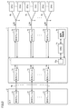
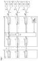
- FIG. 2 is a block diagram illustrating an example of a configuration of each of the OLT and the optical signal relay device illustrated in FIG. 1.
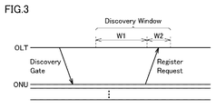
- FIG. 10 is a sequence diagram for explaining OLT discovery processing in the case where no delay of optical signal transmission is set inside the optical signal repeater.
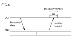
- FIG. 11 is a sequence diagram for explaining OLT discovery processing when a delay of optical signal transmission is set inside the optical signal repeater.
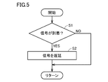
- 3 is a flowchart showing processing of delay elements in the optical signal relay device according to the first embodiment. It is the schematic which shows the structural example of the optical communication system which concerns on the 2nd Embodiment of this invention.
- FIG. 5 is a block diagram illustrating an example of a configuration of an optical signal relay device according to a second embodiment.
- An optical signal relay device is an optical device for relaying an optical signal transmitted between a station-side device and a plurality of home-side devices connected to a branched communication path. It is a signal relay device.
- the optical signal repeater includes a delay element. The delay element is provided between the home-side device connected to the station-side device via the shortest communication path among the branched communication paths and the transmission of the optical signal that transmits the shortest communication path. Delay.
- the optical signal has the shortest transmission time in the communication path with the shortest transmission distance from the station side device.
- the difference between the length of this communication path and the length of another communication path for example, the longest communication path
- the difference in optical signal transmission time is large.
- the delay element can increase the transmission time of the optical signal transmitted through the shortest communication path. Therefore, the difference in transmission time due to the difference in the transmission distance of the optical signal can be reduced.
- the delay time may be fixed or variable.
- the signal to be delayed may be either a signal sent from the station side device, a signal sent from the home side device, or both.
- the signal to be delayed may be a specific type of signal, and the type may not be limited.
- the home-side device connected to the shortest communication path among the plurality of home-side devices is included in the optical signal relay device.
- the delay element delays transmission of an optical signal transmitted between the station-side device and the plurality of home-side devices when the station-side device executes the discovery process.
- the width (bandwidth) of the discovery window set in the station side device can be reduced.
- An optical communication system includes a station-side device, a branched communication path, a plurality of home-side devices connected to the branched communication path, a station-side device, and a plurality of homes
- An optical signal relay device for relaying an optical signal transmitted to each of the side devices.
- the optical signal relay device delays transmission of an optical signal transmitted between the home side device connected to the station side device and the station side device through the shortest communication path among the branched communication paths.
- An optical signal relay method relays an optical signal between a station-side device and a plurality of home-side devices connected to the station-side device via a branched communication path.
- This is an optical signal relay method.
- the optical signal relay method includes a step of delaying transmission of an optical signal transmitted between a home-side device connected to a station-side device and a station-side device through a shortest communication path among branched communication paths.
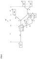
- FIG. 1 is a schematic diagram illustrating a configuration example of an optical communication system 101 according to the first embodiment of the present invention.
- an optical communication system 101 includes a station side device 2, a plurality of home side devices 3a, 3b, 3c, a trunk optical fiber 4a, a plurality of branch optical fibers 4b, an optical splitter 5, And an optical signal relay device 7.
- the station side device is hereinafter referred to as “OLT”, and the home side device is hereinafter referred to as “ONU”.
- FIG. 1 representatively shows three ONUs 3a, 3b, and 3c.
- the number of ONUs included in the optical communication system 101 is not limited.
- the optical communication system 101 is realized as a PON system.
- the IEEE 802.3 standard defines GE-PON and 10G-EPON as PON standards.
- One of the differences between GE-PON and 10G-EPON is the communication speed (transmission rate).
- the optical communication system 101 may be a system including one of GE-PON and 10G-EPON, or may be a system including both GE-PON and 10G-EPON.
- the communication speed (transmission rate) of GE-PON is 1.25 Gbps (bit per second).
- the transmission rate of 10G-EPON is 10.3125 Gbps.
- the trunk optical fiber 4a is connected to the OLT 2.
- Each branch optical fiber 4b is connected to a corresponding ONU.
- the optical splitter 5 connects the trunk optical fiber 4a and a plurality of branch optical fibers 4b. Therefore, the ONUs 3a, 3b, and 3c are connected to the branched communication path.
- the optical splitter 5 is connected to the trunk optical fiber 4a and the plurality of branch optical fibers 4b.
- the optical splitter 5 distributes the optical signal transmitted through the trunk optical fiber 4a to the plurality of branch optical fibers 4b.
- the optical splitter 5 multiplexes the optical signals sent from the plurality of branch optical fibers 4b and sends them to the trunk optical fiber 4a.
- the optical signal relay device 7 is a device that relays an optical signal transmitted between the OLT 2 and each of the ONUs 3a, 3b, and 3c.
- the optical signal relay device 7 makes it possible to extend the transmission distance of the optical signal.
- the optical signal relay device 7 converts the optical signal into an electric signal.
- the optical signal repeater 7 performs processing such as amplification and clock regeneration on the electrical signal.
- the optical signal relay device 7 converts the electrical signal into an optical signal and sends out the optical signal.
- the ONUs 3a, 3b, and 3c are disposed downstream of the optical signal relay device 7 in the optical signal communication path.
- L1 is the length of the communication path from the OLT 2 to the optical signal repeater 7.
- L2 is the length of the communication path from the optical signal repeater 7 to the ONU 3a.
- L3 is the length of the communication path between the ONU 2a and the ONUs 3b and 3c.
- the “communication path length” is also referred to as “distance” below. According to the configuration example shown in FIG. 1, L3> 0. That is, the ONUs 3b and 3c are located farther from the OLT 2 than the ONU 3a.
- FIG. 2 is a block diagram showing an example of the configuration of each of the OLT and the optical signal repeater shown in FIG. Main parts of the OLT 2 and the optical signal repeater 7 are shown in FIG.
- OLT 2 includes a plurality of optical modules 21.
- Each optical module 21 converts an electrical signal into an optical signal and sends the optical signal to the trunk optical fiber 4a.
- the optical module 21 receives an optical signal via the trunk optical fiber 4a and converts the optical signal into an electrical signal.
- An electrical signal is transmitted inside the OLT 2.
- an optical signal can be transmitted between the plurality of optical modules 21 and the optical signal repeater 7 by, for example, time division multiplexing or wavelength multiplexing.
- the optical signal relay device 7 includes a plurality of optical modules 71, a transmission control unit 72, a plurality of optical modules 73, an ONU 74, and a monitoring control unit 75.
- Each of the plurality of optical modules 71 transmits and receives optical signals to and from the corresponding optical module 21 among the plurality of optical modules 21 of the OLT 2.
- Each optical module 71 converts the optical signal from the corresponding optical module 21 into an electrical signal.
- each optical module 71 converts the electrical signal from the corresponding optical module 73 into an optical signal, and sends the optical signal to the trunk optical fiber 4a.
- Each of the plurality of optical modules 73 is connected to the optical splitter 5 through a trunk optical fiber.
- a plurality of branch optical fibers 4 b are branched from each optical splitter 5.
- the ONU 3 is connected to the branch line optical fiber 4 b branched from the optical splitter 5.
- the number of branch optical fibers 4b branched from the optical splitter 5 is not particularly limited.
- Each optical module 73 exchanges optical signals with the ONU 3 connected to the optical module 73. Further, each optical module 73 exchanges electrical signals with the corresponding optical module 71.
- the optical module 73 converts the electrical signal from the optical module 71 into an optical signal and sends the optical signal to the optical fiber.
- the optical module 73 converts the optical signal from the ONU 3 into an electrical signal and transmits the electrical signal to the corresponding optical module 71.
- the transmission control unit 72 sets signal paths between the plurality of optical modules 71 and the plurality of optical modules 73.
- the transmission control unit 72 can change the signal path.
- the ONU 74 monitors and controls the optical signal relay device 7.
- the ONU 74 enables remote monitoring on the station (center) side, for example.
- the monitoring control unit 75 controls the ONU 74 and the transmission control unit 72.
- the ONU 74 has the same function as that of the ONU 3.
- the transmission control unit 72 includes a delay element 72a.
- the delay element 72a delays transmission of a signal sent to the ONU 74.
- the delay element 72a may delay transmission of a signal sent from the ONU 74.
- the delay element 72a may delay transmission of both the signal sent to the ONU 74 and the signal sent from the ONU 74.
- the delay element 72a when the delay element 72a receives a message, the delay element 72a holds the message for a certain period of time. After that time has elapsed, the delay element 72a outputs the message.
- the delay time corresponds to the time for holding the message.
- the delay element 72a may be realized by a dedicated circuit, or may be configured as a part of the transmission control unit 72 by software that operates the transmission control unit 72.
- the transmission control unit 72 can be realized by, for example, an FPGA (Field Programmable Gate Array).
- the delay element 72a may identify the type of message sent in the form of an electrical signal.
- the delay element 72a may delay transmission of a specific type of signal (message) among signals transmitted between the ONU 74 and the OLT 2.
- the delay element 72a may delay signal transmission between the ONU 74 and the OLT 2 regardless of the type of signal.
- the transmission delay time in the delay element 72a is preset.
- the set delay time is greater than 0 and less than or equal to the time required for the optical signal to transmit the distance (L2 + L3).
- the delay time is not less than the time required for the optical signal to transmit the distance L2 and not more than the time required for the optical signal to transmit the distance (L2 + L3). More preferably, the delay time is equal to the time required for the optical signal to travel the distance L2.
- the delay time may be set dynamically.
- the delay time can be set from the transmission time of the optical signal between the OLT 2 and the ONU 74 and the transmission time of the optical signal between the OLT 2 and each ONU 3.
- the delay time may be set so that the delay time falls within the above range.
- FIG. 3 is a sequence diagram for explaining the OLT discovery process in the case where the optical signal transmission delay is not set inside the optical signal repeater.
- OLT 2 broadcasts a discovery gate (Discovery Gate) to the ONU.
- the ONU that has received the discovery gate transmits a registration request frame (Register Request) after a random delay time.
- Discovery Gate Discovery Gate
- Registered Request Registration request frame
- the OLT sets a time window called a discovery window for discovery and registration of the ONU.
- a discovery window for discovery and registration of the ONU.
- the distance from the OLT 2 to each ONU can be different. For this reason, the width of the discovery window needs to consider the transmission distance of the optical signal between the OLT 2 and the ONU closest to the OLT 2 and the distance of the optical signal between the OLT 2 and the ONU furthest from the OLT 2 .
- the ONU closest to the OLT 2 is the ONU 74 inside the optical signal relay device 7.
- the ONU farthest from the OLT 2 is the ONU 3b or the ONU 3c.
- the distance from OLT2 to ONU3b or ONU3c is (L1 + L2 + L3).
- the discovery window can be represented by the sum of window W1 and window W2.
- Window W1 is a band corresponding to distance L2.
- the window W2 is a band corresponding to the distance L3.
- FIG. 4 is a sequence diagram for explaining the OLT discovery process in the case where the delay of optical signal transmission is set inside the optical signal repeater.
- ONU 74 is provided in a communication path having a shortest transmission distance from OLT 2 among the branched communication paths.
- the delay element 72a delays the transmission of the discovery gate from the OLT 2 to the ONU 74.
- the delay time is set to be substantially the same as the time required for the discovery gate to transmit the distance L2.
- the distance from the OLT 2 to the ONU 74 is equal to (L1 + L2).
- the ONU 74 is virtually at the same position as the ONU 3a. Thereby, the difference in the transmission time of the optical signal between the plurality of ONUs connected to the branched communication path can be reduced.
- the width (band) of the discovery window corresponds to the difference between the distance L2 and the distance (L2 + L3), that is, the band corresponding to the distance L3.
- the width of the discovery window can be reduced.
- the transmission delay time in the delay element 72a only needs to be larger than zero.
- the delay time becomes longer than the time required for the optical signal to transmit the distance (L2 + L3)
- the ONU 74 is virtually located farther from the OLT 2 than the ONUs 3b and 3c.
- the width of the discovery window becomes larger than the width of the window W2. Accordingly, the delay time is greater than 0 and less than or equal to the time required for the optical signal to transmit the distance (L2 + L3).
- the delay time is set so that the width of the discovery window corresponds to the width of the window W2. Therefore, the delay time is preferably equal to or longer than the time required for the optical signal to transmit the distance L2 and equal to or shorter than the time required for the optical signal to transmit the distance (L2 + L3). More preferably, the delay time is equal to the time required for the optical signal to travel the distance L2.
- the ONU when the ONU receives the discovery gate, the ONU transmits a registration request frame after the random delay time has elapsed. Therefore, the upper limit and the lower limit of the delay time range can be set in consideration of the range of the random delay time.
- the delay element 72a may delay the transmission of the signal from the ONU 74. Also in this case, the delay time can be set so that the delay time falls within the above range.
- the delay element 72a delays the transmission of both the signal from the OLT 2 (optical module 71) and the signal from the ONU 74, the total delay time of the transmission of each signal falls within the above range.
- the delay time of transmission of each signal can be set.
- FIG. 5 is a flowchart showing processing of delay elements in the optical signal repeater according to the first embodiment.
- the process shown in FIG. 5 is repeatedly executed at a constant cycle, for example. 2 and 5, the transmission control unit 72 determines whether or not the signal has arrived at the delay element 72a (step S1).
- the transmission control unit 72 sets a signal transmission path between any one of the plurality of optical modules 71 and the ONU 74.
- the delay element 72a receives a signal through the path, the transmission control unit 72 determines that the signal has arrived at the delay element 72a.
- the signal to be determined may be either a signal from the optical module 71, a signal from the ONU 74, or both signals.
- step S1 When a signal arrives at the delay element 72a (YES in step S1), the delay element 72a delays transmission of the signal (step S2). On the other hand, when the signal does not arrive at delay element 72a (NO in step S1), the process of delay element 72a is not executed.
- the optical signal relay device 7 has the ONU 74 for monitoring.
- the delay element 72a delays transmission of a signal transmitted between the ONU 74 and the OLT 2.
- the difference in the transmission time due to the difference in the transmission distance of the optical signal between the station side device and the plurality of home side devices connected to the branched communication path can be reduced. Therefore, for example, the bandwidth of the discovery window can be reduced in the OLT, so that the throughput can be improved.
- An optical signal repeater that does not include a monitoring ONU can also be applied to an optical communication system.
- the delay time is determined based on the length of the communication path between ONUs connected to the optical signal repeater through the branched communication path.
- FIG. 6 is a schematic diagram showing a configuration example of the optical communication system 102 according to the second embodiment of the present invention.
- the configuration of optical communication system 102 is basically the same as that of optical communication system 101 shown in FIG.
- the optical signal relay device 7 branches the communication path from the OLT 2 into, for example, two. For example, it has two ports.
- ONUs 3 a, 3 b, 3 c are connected to the first port via branch optical fiber 4 b and optical splitter 5.
- the ONUs 3d, 3e, and 3f are connected to the second port via the branch optical fiber 4b and the optical splitter 5.
- L4 is the distance from the optical signal repeater 7 to the ONU 3d.
- L5 is the distance from ONU 3d to ONU 3e, 3f. In the following description, it is assumed that L4 ⁇ L2 and L5 ⁇ L3.
- the distances L1, L2, and L3 shown in FIG. 6 are the same as the distances L1, L2, and L3 in the first embodiment.
- the optical signal relay device 7 includes a delay element 72a.
- the delay element 72a is provided on the shortest communication path among the branched communication paths. In the example shown in FIG. 6, the delay element 72a is provided in a communication path between the OLT 2 and the ONU 3d, and delays signal transmission in the communication path.
- FIG. 7 is a block diagram showing an example of the configuration of the optical signal repeater according to the second embodiment.
- optical signal repeater 7 is different from the optical signal repeater shown in FIG. 2 in that ONU 74 is omitted.
- the configuration of the other part of the optical signal repeater shown in FIG. 7 is the same as the configuration of the corresponding part shown in FIG.
- the transmission control unit 72 sets a communication path so that a signal from one optical module 71 is branched to two optical modules 73. Signals from each of these two optical modules 73 are transmitted to the optical module 71 by the transmission control unit 72. Therefore, the configuration shown in FIG. 6 can be realized.
- the delay element 72a delays signal transmission in the path to which the ONUs 3d to 3f are connected out of the two communication paths. Since the processing of delay element 72a is the same as the processing shown in FIG. 5, the following description will not be repeated.
- delay element 72a does not delay the transmission of signals to ONU 3d to ONU 3f
- the delay element 72a delays the transmission of the signal sent to the ONU (ONU 3d) closest to the OLT 2 for the time required for the optical signal to transmit the distance (L2-L4).
- the transmission distance of the signal from the OLT 2 to the ONU 3d is virtually the same as the transmission distance of the signal from the OLT 2 to the ONU 3a. Therefore, according to the second embodiment, the width of the discovery window can be reduced as shown in FIG.
- the delay time is preferably greater than 0 and less than or equal to the time required for the optical signal to transmit the distance ⁇ (L2 + L3) ⁇ (L4 + L5) ⁇ . More preferably, the delay time is equal to or longer than the time required for the optical signal to transmit the distance (L2 ⁇ L4) and equal to or shorter than the time required for the optical signal to transmit the distance ⁇ (L2 + L3) ⁇ (L4 + L5) ⁇ . is there. Further preferably, the delay time is equal to the time required for the optical signal to travel the distance (L2-L4). In this case, the width of the window W2 can be a width corresponding to the distance L3.
- the delay time is preferably greater than 0 and less than or equal to the time required for the optical signal to transmit the distance (L2-L4).
- the delay time is equal to or longer than the time required for the optical signal to transmit the distance ⁇ (L2 + L3) ⁇ (L4 + L5) ⁇ and equal to or shorter than the time required for the optical signal to transmit the distance (L2 ⁇ L4).
- the delay time is equal to the time required for the optical signal to transmit the distance ⁇ (L2 + L3) ⁇ (L4 + L5) ⁇ .
- the width of the window W2 can be a width corresponding to the distance L5.
- the transmission distance of the optical signal between the station-side device and the plurality of home-side devices connected to the branched communication path is The difference in transmission time due to the difference can be reduced.
- the bandwidth of the discovery window can be reduced in the OLT, so that the throughput can be improved.
- the delay element 72a may delay transmission of a specific type of signal (message). Alternatively, the delay element 72a may delay signal transmission regardless of the type of signal. Further, the delay element 72a may delay the transmission of the signal sent from the ONU 3d. Alternatively, the delay element 72a may delay transmission of both the signal sent from the OLT 2 to the ONU 3d and the signal sent from the ONU 3d.
Landscapes
- Engineering & Computer Science (AREA)
- Computer Networks & Wireless Communication (AREA)
- Signal Processing (AREA)
- Physics & Mathematics (AREA)
- Electromagnetism (AREA)
- Computing Systems (AREA)
- Small-Scale Networks (AREA)
- Optical Communication System (AREA)
Abstract
Description
最初に本発明の実施態様を列記して説明する。
以下、本発明の実施の形態について図面を用いて説明する。なお、図中同一または相当部分には同一符号を付してその説明は繰り返さない。
図1は、本発明の第1の実施形態に係る光通信システム101の構成例を示す概略図である。図1を参照して、光通信システム101は、局側装置2と、複数の宅側装置3a,3b,3cと、幹線光ファイバ4aと、複数の支線光ファイバ4bと、光スプリッタ5と、光信号中継装置7とを備える。局側装置を以下「OLT」と称し、宅側装置を以下「ONU」と称する。なお、図が複雑になるのを避けるために、図1では、代表的に3台のONU3a,3b,3cが示されている。しかしながら、光通信システム101に含まれるONUの台数は限定されるものではない。
監視用のONUを内蔵していない光信号中継装置も、光通信システムに適用され得る。このような光通信システムにおいては、分岐された通信経路を通じて光信号中継装置に接続されたONUの間の通信経路の長さに基づいて遅延時間が定められる。
Claims (5)
- 局側装置と、分岐された通信経路に接続された複数の宅側装置との間で伝送される光信号を中継するための光信号中継装置であって、
前記分岐された通信経路のうち最短の通信経路で前記局側装置に接続される宅側装置と、前記局側装置との間に設けられて、前記最短の通信経路を伝送する光信号の伝送を遅延させるための遅延要素を備える、光信号中継装置。 - 前記複数の宅側装置のうち、前記最短の通信経路に接続された宅側装置は、前記光信号中継装置に含まれる、請求項1に記載の光信号中継装置。
- 前記遅延要素は、前記局側装置がディスカバリ処理を実行するときに前記局側装置と前記複数の宅側装置との間で伝送される光信号の伝送を遅延させる、請求項1または請求項2に記載の光信号中継装置。
- 局側装置と、
分岐された通信経路と、
前記分岐された通信経路に接続された複数の宅側装置と、
前記局側装置と前記複数の宅側装置の各々との間で伝送される光信号を中継するための光信号中継装置とを備え、
前記光信号中継装置は、前記分岐された通信経路のうち最短の通信経路で局側装置に接続される宅側装置と、前記局側装置との間を伝送する光信号の伝送を遅延させる、光通信システム。 - 局側装置と、分岐された通信経路を介して前記局側装置に接続された複数の宅側装置との間で光信号を中継するための光信号中継方法であって、
前記分岐された通信経路のうち最短の通信経路で局側装置に接続される宅側装置と、前記局側装置との間を伝送する光信号の伝送を遅延させるステップを備える、光信号中継方法。
Priority Applications (2)
| Application Number | Priority Date | Filing Date | Title |
|---|---|---|---|
| CA2952201A CA2952201A1 (en) | 2015-05-13 | 2016-01-26 | Optical signal repeater, optical communication system, and method of repeating optical signal |
| US15/316,557 US20170187461A1 (en) | 2015-05-13 | 2016-01-26 | Optical signal repeater, optical communication system, and method of repeating optical signal |
Applications Claiming Priority (2)
| Application Number | Priority Date | Filing Date | Title |
|---|---|---|---|
| JP2015097868A JP2016213770A (ja) | 2015-05-13 | 2015-05-13 | 光信号中継装置、光通信システムおよび光信号中継方法 |
| JP2015-097868 | 2015-05-13 |
Publications (1)
| Publication Number | Publication Date |
|---|---|
| WO2016181668A1 true WO2016181668A1 (ja) | 2016-11-17 |
Family
ID=57248094
Family Applications (1)
| Application Number | Title | Priority Date | Filing Date |
|---|---|---|---|
| PCT/JP2016/052130 Ceased WO2016181668A1 (ja) | 2015-05-13 | 2016-01-26 | 光信号中継装置、光通信システムおよび光信号中継方法 |
Country Status (4)
| Country | Link |
|---|---|
| US (1) | US20170187461A1 (ja) |
| JP (1) | JP2016213770A (ja) |
| CA (1) | CA2952201A1 (ja) |
| WO (1) | WO2016181668A1 (ja) |
Families Citing this family (2)
| Publication number | Priority date | Publication date | Assignee | Title |
|---|---|---|---|---|
| US11863235B2 (en) * | 2019-07-16 | 2024-01-02 | Sumitomo Electric Industries, Ltd. | Optical network system and automatic operation system |
| CN117713920A (zh) * | 2022-09-06 | 2024-03-15 | 华为技术有限公司 | 通信处理方法以及相关装置 |
Citations (3)
| Publication number | Priority date | Publication date | Assignee | Title |
|---|---|---|---|---|
| WO2007119589A1 (ja) * | 2006-03-31 | 2007-10-25 | The Furukawa Electric Co., Ltd. | 光伝送システム及び光中継装置 |
| JP2010171641A (ja) * | 2009-01-21 | 2010-08-05 | Nippon Telegr & Teleph Corp <Ntt> | 光加入者線終端装置および光加入者システム |
| US20100310252A1 (en) * | 2007-10-24 | 2010-12-09 | Peter Healey | Optical communication |
Family Cites Families (1)
| Publication number | Priority date | Publication date | Assignee | Title |
|---|---|---|---|---|
| US20090310615A1 (en) * | 2008-06-13 | 2009-12-17 | Tellabs Vienna, Inc. | Logical geographical and subscriber ONT subgroups in support of fiber-to-the-premises (FTTP) architecture |
-
2015
- 2015-05-13 JP JP2015097868A patent/JP2016213770A/ja not_active Withdrawn
-
2016
- 2016-01-26 WO PCT/JP2016/052130 patent/WO2016181668A1/ja not_active Ceased
- 2016-01-26 US US15/316,557 patent/US20170187461A1/en not_active Abandoned
- 2016-01-26 CA CA2952201A patent/CA2952201A1/en not_active Abandoned
Patent Citations (3)
| Publication number | Priority date | Publication date | Assignee | Title |
|---|---|---|---|---|
| WO2007119589A1 (ja) * | 2006-03-31 | 2007-10-25 | The Furukawa Electric Co., Ltd. | 光伝送システム及び光中継装置 |
| US20100310252A1 (en) * | 2007-10-24 | 2010-12-09 | Peter Healey | Optical communication |
| JP2010171641A (ja) * | 2009-01-21 | 2010-08-05 | Nippon Telegr & Teleph Corp <Ntt> | 光加入者線終端装置および光加入者システム |
Also Published As
| Publication number | Publication date |
|---|---|
| JP2016213770A (ja) | 2016-12-15 |
| CA2952201A1 (en) | 2016-11-17 |
| US20170187461A1 (en) | 2017-06-29 |
Similar Documents
| Publication | Publication Date | Title |
|---|---|---|
| CN107407777B (zh) | 用于光网络的系统和方法 | |
| US10404392B2 (en) | Method and apparatus for determining propagation delay in a communications network | |
| US9112612B2 (en) | Relay device, station-side optical communication device, communication system, and bandwidth allocation method | |
| JP4860137B2 (ja) | 光アクセスネットワーク方法及び光アクセスネットワーク並びに光アクセスネットワーク用光スイッチ | |
| US9871614B2 (en) | WDM/TDM-PON system and transmission start time correction method thereof | |
| JP6449060B2 (ja) | 波長分離多重装置及び光通信システム並びに波長分離多重方法 | |
| JP4913876B2 (ja) | 帯域割当装置および帯域割当方法 | |
| JP2015050623A (ja) | 局側終端装置及び経路切替方法 | |
| CN101577590B (zh) | 一种信号传输方法、中继设备以及无源光网络系统 | |
| CA2846591A1 (en) | Pon system, station side device and method for operating the same, and access control device | |
| JP2016213770A (ja) | 光信号中継装置、光通信システムおよび光信号中継方法 | |
| JP5846007B2 (ja) | 加入者側装置登録方法及び光ネットワークシステム | |
| JP5456547B2 (ja) | 光通信システム及び光通信方法 | |
| JP2013207716A (ja) | 加入者側装置登録方法 | |
| JP2018098556A (ja) | 光リングネットワークシステム及びそのパス制御方法 | |
| JP2012129942A (ja) | 光通信システム | |
| White et al. | Design of a control-channel-based media-access-control protocol for HORNET | |
| JP5733589B2 (ja) | Pon光通信システム用中継方法 | |
| JP5133277B2 (ja) | 光加入者線終端装置および光加入者システム | |
| JP6684066B2 (ja) | 局側光終端装置及び等化処理共通化方法 | |
| JP5553153B2 (ja) | Pon光通信システム用中継方法並びにこの方法を用いたpon光通信システム用中継器及びpon光通信システム | |
| US20040175175A1 (en) | Optical packet router for an optical node in a packet switched WDM optical network | |
| CN103686465B (zh) | 光网络节点、光网络单元和低延时的光网络单元间的通信 | |
| JP4958984B2 (ja) | 帯域割当装置および帯域割当方法 | |
| WO2017097020A1 (zh) | 一种无源光网络兼容装置及其实现方法和光线路终端 |
Legal Events
| Date | Code | Title | Description |
|---|---|---|---|
| WWE | Wipo information: entry into national phase |
Ref document number: 15316557 Country of ref document: US |
|
| ENP | Entry into the national phase |
Ref document number: 2952201 Country of ref document: CA |
|
| 121 | Ep: the epo has been informed by wipo that ep was designated in this application |
Ref document number: 16792394 Country of ref document: EP Kind code of ref document: A1 |
|
| NENP | Non-entry into the national phase |
Ref country code: DE |
|
| 122 | Ep: pct application non-entry in european phase |
Ref document number: 16792394 Country of ref document: EP Kind code of ref document: A1 |