WO2016178270A1 - Dispositif de radar - Google Patents
Dispositif de radar Download PDFInfo
- Publication number
- WO2016178270A1 WO2016178270A1 PCT/JP2015/063087 JP2015063087W WO2016178270A1 WO 2016178270 A1 WO2016178270 A1 WO 2016178270A1 JP 2015063087 W JP2015063087 W JP 2015063087W WO 2016178270 A1 WO2016178270 A1 WO 2016178270A1
- Authority
- WO
- WIPO (PCT)
- Prior art keywords
- doppler
- unit
- angle
- frequency range
- processing unit
- Prior art date
Links
Images

Classifications
-
- G—PHYSICS
- G01—MEASURING; TESTING
- G01S—RADIO DIRECTION-FINDING; RADIO NAVIGATION; DETERMINING DISTANCE OR VELOCITY BY USE OF RADIO WAVES; LOCATING OR PRESENCE-DETECTING BY USE OF THE REFLECTION OR RERADIATION OF RADIO WAVES; ANALOGOUS ARRANGEMENTS USING OTHER WAVES
- G01S13/00—Systems using the reflection or reradiation of radio waves, e.g. radar systems; Analogous systems using reflection or reradiation of waves whose nature or wavelength is irrelevant or unspecified
- G01S13/02—Systems using reflection of radio waves, e.g. primary radar systems; Analogous systems
- G01S13/06—Systems determining position data of a target
- G01S13/42—Simultaneous measurement of distance and other co-ordinates
-
- G—PHYSICS
- G01—MEASURING; TESTING
- G01S—RADIO DIRECTION-FINDING; RADIO NAVIGATION; DETERMINING DISTANCE OR VELOCITY BY USE OF RADIO WAVES; LOCATING OR PRESENCE-DETECTING BY USE OF THE REFLECTION OR RERADIATION OF RADIO WAVES; ANALOGOUS ARRANGEMENTS USING OTHER WAVES
- G01S13/00—Systems using the reflection or reradiation of radio waves, e.g. radar systems; Analogous systems using reflection or reradiation of waves whose nature or wavelength is irrelevant or unspecified
- G01S13/02—Systems using reflection of radio waves, e.g. primary radar systems; Analogous systems
- G01S13/50—Systems of measurement based on relative movement of target
- G01S13/52—Discriminating between fixed and moving objects or between objects moving at different speeds
- G01S13/522—Discriminating between fixed and moving objects or between objects moving at different speeds using transmissions of interrupted pulse modulated waves
- G01S13/524—Discriminating between fixed and moving objects or between objects moving at different speeds using transmissions of interrupted pulse modulated waves based upon the phase or frequency shift resulting from movement of objects, with reference to the transmitted signals, e.g. coherent MTi
-
- G—PHYSICS
- G01—MEASURING; TESTING
- G01S—RADIO DIRECTION-FINDING; RADIO NAVIGATION; DETERMINING DISTANCE OR VELOCITY BY USE OF RADIO WAVES; LOCATING OR PRESENCE-DETECTING BY USE OF THE REFLECTION OR RERADIATION OF RADIO WAVES; ANALOGOUS ARRANGEMENTS USING OTHER WAVES
- G01S13/00—Systems using the reflection or reradiation of radio waves, e.g. radar systems; Analogous systems using reflection or reradiation of waves whose nature or wavelength is irrelevant or unspecified
- G01S13/88—Radar or analogous systems specially adapted for specific applications
- G01S13/95—Radar or analogous systems specially adapted for specific applications for meteorological use
-
- Y—GENERAL TAGGING OF NEW TECHNOLOGICAL DEVELOPMENTS; GENERAL TAGGING OF CROSS-SECTIONAL TECHNOLOGIES SPANNING OVER SEVERAL SECTIONS OF THE IPC; TECHNICAL SUBJECTS COVERED BY FORMER USPC CROSS-REFERENCE ART COLLECTIONS [XRACs] AND DIGESTS
- Y02—TECHNOLOGIES OR APPLICATIONS FOR MITIGATION OR ADAPTATION AGAINST CLIMATE CHANGE
- Y02A—TECHNOLOGIES FOR ADAPTATION TO CLIMATE CHANGE
- Y02A90/00—Technologies having an indirect contribution to adaptation to climate change
- Y02A90/10—Information and communication technologies [ICT] supporting adaptation to climate change, e.g. for weather forecasting or climate simulation
Definitions
- the present invention relates to a radar apparatus having a resolution exceeding an angular resolution determined by a beam width using an array antenna capable of measuring an angle.
- weather radar detects the intensity of echoes reflected by rain particles such as clouds and rain, and uses the Doppler effect of reflected waves to detect dynamic changes in rain and clouds in order to observe or predict weather conditions.
- a pulse Doppler radar that can be captured is used.
- transmission pulses are repeatedly emitted at a required repetition interval. This pulse repetition period is determined by the maximum distance of the target to be detected.
- the minimum distance between two targets that can identify different targets in the same direction from the radar as two targets is determined by the transmission pulse width.
- the minimum azimuth difference between two targets that can identify different targets in the same distance from the radar as two targets is determined by the beam width of the antenna.
- weather radar assumes a uniform wind as a premise to blow within the same angle range and the same distance range, and observes the variation in the wind by the Doppler velocity width (for example, non-patent document). 1).
- the frequency spectrum of the received echo has a total shape in which a plurality of Gaussian distributions are overlapped, so that the Doppler velocity width is widened.
- the speed range is wide, it is estimated that the component moves variously, but it is still assumed that the premise is a uniform wind. Therefore, there has been a problem that the difference between the estimation result and the reality becomes large.
- the present invention has been made to solve such a problem, and an object of the present invention is to obtain a radar apparatus capable of realizing sufficient angular resolution even when a beam having a wide shape is used.
- a radar apparatus includes a pulse Doppler processing unit that performs pulse Doppler processing on each signal received by a plurality of antennas, and a frequency range of a Doppler spectrum output from the pulse Doppler processing unit.
- a frequency division unit that divides the frequency range, a doppler spectrum between the same frequency ranges in the divided frequency range, and an angle measurement processing unit that performs angle measurement processing for each divided frequency range, and for each divided frequency range
- an output unit that outputs the angle measurement processing result as a direction for each angle range obtained by dividing the angle determined by the beam widths of the plurality of antennas by the number of divisions of the frequency range.
- the radar apparatus divides the frequency range of the Doppler spectrum into a plurality of frequency ranges, and performs angle measurement processing for each divided frequency range using the Doppler spectra of the same frequency range in the divided frequency range. It is what I did. Thereby, even when a beam having a wide shape is used, sufficient angular resolution can be realized.
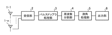
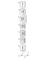
- FIG. 1 is a configuration diagram of a radar apparatus according to the present embodiment.
- the radar apparatus according to the present embodiment includes antennas 1-1 to 1-n, a receiving unit 2, a pulse Doppler processing unit 3, a frequency division unit 4, an angle measurement processing unit 5, and an output unit 6.
- Antennas 1-1 to 1-n are element antennas of an array antenna in which a plurality of element antennas are arranged as transmission antennas or reception antennas of a radar apparatus.
- the receiving unit 2 is a processing unit that acquires received signals from the antennas 1-1 to 1-n.
- the configuration of the transmission system in the radar apparatus is not directly related to the present invention, and thus illustration and description thereof are omitted.
- the pulse Doppler processing unit 3 is a processing unit that performs pulse Doppler processing on the two received signals from the receiving unit 2.
- the frequency dividing unit 4 divides the Doppler frequency range observable by the radar into a plurality of small ranges and proceeds to the next angle measurement process using only the data of each range, so that the output from the pulse Doppler processing unit 3
- the angle measurement processing unit 5 is a processing unit that performs angle measurement processing using signals in the same frequency range divided by the frequency division unit 4.
- the output unit 6 determines the direction for each angle range obtained by dividing the angle determined by the beam width of the antennas 1-1 to 1-n by the number of divisions in the frequency division unit 4 based on the angle measurement processing result in the angle measurement processing unit 5.
- FIG. 2 is an explanatory diagram showing the concept of angle measurement processing of the radar apparatus according to the first embodiment.
- the two antenna elements are divided into equal frequency ranges, and angle measurement processing is performed using the data of each range, thereby associating the spectrum and direction of each Gaussian distribution. it can. That is, it is possible to correlate from which part within the same distance range the wind having each divided Doppler frequency is.
- FIG. 3 is an explanatory diagram illustrating the operation of the radar apparatus according to the first embodiment.
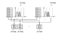
- Radio waves are transmitted from the two antennas 1-1 to 1-2, and reflected waves from the target are received by the receiving unit 2 (steps ST101a and ST101b), and each signal is subjected to pulse Doppler processing by the pulse Doppler processing unit 3.
- Steps ST102a and ST102b the pulse Doppler process is a process for obtaining the Doppler spectrum from the signal received by the receiving unit 2, and since this is known, a detailed description thereof is omitted here.
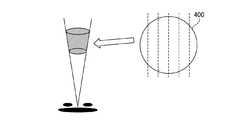
- the frequency dividing unit 4 divides the Doppler spectrum output from the pulse Doppler processing unit 3 into six frequency ranges, respectively (Steps ST103a and ST103b). Thereby, the spectrum of each Gaussian distribution is reproduced from the total spectrum in which a plurality of Gaussian distributions overlap. As shown in FIG. 4, this corresponds to dividing the beam 400 viewed from the front into six equal parts in the horizontal direction as shown by broken lines, that is, azimuthally divided into six parts.
- FIG. 5 is an explanatory diagram of frequency range division in the frequency division unit 4. As shown in FIG. 5, the Doppler spectrum from the frequency division unit 4 is divided into six frequency ranges, and two data in the same frequency range are output to the angle measurement processing unit 5.
- the angle measurement processing unit 5 performs angle measurement processing using Doppler spectra in the same frequency range of the six Doppler spectra output from the frequency division unit 4 (steps ST104a to ST104f). That is, the angle measurement processing unit 5 estimates the arrival direction of the incoming wave from which direction the signal is within the range of each of the six beam widths divided by the arrival direction estimation method.
- the arrival direction estimation method the output of each element antenna is multiplied by an appropriate complex weight. That is, by appropriately manipulating the amplitude and phase of the received signal of each element antenna, the directivity of the array antenna can be given to an arbitrary directivity.
- the received signal strength with each azimuth within the detection range as the directional azimuth is detected, and the directional azimuth at which the received signal strength peaks among the directional azimuths is estimated as the arrival azimuth of the incoming wave.
- the arrival direction of the incoming wave may be estimated with the NULL point of the directivity characteristic directed to an arbitrary direction.
- Various methods such as Beamformer method, Capon method and MUSIC (Multiple Signal Classification) method are known as arrival direction estimation methods. These arrival direction estimation methods are selected according to conditions and the like. By such angle measurement processing, the spectrum and direction of each Gaussian distribution can be associated.
- the output unit 6 associates the result of each angle measurement processing divided into 6 with which part of the divided Doppler frequency wind is within the same angle range and the same distance range. Output (step ST105).
- a pulse Doppler processing unit that performs pulse Doppler processing on each signal received by a plurality of antennas, and a Doppler output from the pulse Doppler processing unit.
- Angle measurement processing that performs angle measurement processing for each divided frequency range using a frequency division unit that divides the frequency range of the spectrum into a plurality of frequency ranges, and a Doppler spectrum between the same frequency ranges in the divided frequency ranges
- an output unit for outputting the angle measurement processing results for each divided frequency range as directions for each angle range obtained by dividing the angle determined by the beam widths of the plurality of antennas by the number of divided frequency ranges.
- the same angle range and the same distance range it can be further divided into multiple areas, which are determined by the beam width It is possible to realize a resolution exceeding the time resolution, for example, it is possible to realize a sufficient resolution even when performing estimation of sudden weather change such as a microburst or wind shear.
- the radar apparatus of the first embodiment since the direction for each angle range obtained by dividing the angle determined by the beam widths of the plurality of antennas by the number of divisions of the frequency range is the horizontal direction, Within the same distance range, it is possible to realize a resolution exceeding the resolution of the direction determined by the beam width. By improving the azimuth resolution, for example, the effect can be expected particularly when the wind direction changes in a layered manner with respect to the azimuth.
- Embodiment 2 the method is effective in a state where the spectrum width is wide.
- the spectrum width is narrow, there is a high possibility that the wind is uniform in the same angle range and the same distance range. In that case, it may not be effective to perform the processing of the first embodiment. Therefore, in the second embodiment, when the received signal obtained for each element antenna is subjected to pulse Doppler processing, if the Doppler velocity width is narrow, angle measurement processing is performed without dividing the range into a plurality of frequencies. It is.
- FIG. 6 is a block diagram showing the configuration of the radar apparatus according to Embodiment 2 of the present invention.
- the radar apparatus according to the second embodiment includes antennas 1-1 to 1-n, a receiving unit 2, a pulse Doppler processing unit 3, a frequency dividing unit 4, an angle measurement processing unit 5, an output unit 6, a Doppler velocity width estimation unit 7, A Doppler speed width comparison unit 8 is provided.
- the Doppler velocity width estimation unit 7 is a processing unit that estimates the frequency range of the Doppler spectrum processed by the pulse Doppler processing unit 3, that is, the Doppler velocity width, and the Doppler velocity width comparison unit 8 estimates the Doppler velocity width estimation unit 7. It is determined whether or not the Doppler velocity width is narrower than the set value.
- the Doppler spectrum in the pulse Doppler processing unit 3 is output to the angle measurement processing unit 5 as it is, and if it is greater than or equal to the set value , A processing unit that outputs to the frequency division unit 4. In addition, about a setting value, it selects suitably. Further, in FIG. 6, since each other configuration is the same as the configuration of the first embodiment shown in FIG. 1, the same reference numerals are given to the corresponding portions, and the description thereof is omitted.
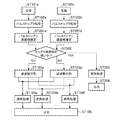
- FIG. 7 is an explanatory diagram showing the operation of the radar apparatus according to the second embodiment.
- the reception operation steps ST101a and ST101b
- the pulse Doppler process steps ST102a and ST102b
- the Doppler velocity width estimation unit 7 estimates the frequency width (Doppler velocity width) of the Doppler spectrum output from the pulse Doppler processing unit 3 (Steps ST201a and ST201b), and compares the Doppler velocity widths.
- the unit 8 determines whether or not the frequency width is narrower than the set value (step ST202). In step ST202, if the frequency width is equal to or larger than the set value, the same operation as in the first embodiment is performed (steps ST103a, ST103b, steps ST104a to ST104f, step ST105).
- step ST202 if the frequency width of the Doppler spectrum is narrower than the set value in step ST202, the frequency division unit 4 does not perform frequency division, and the angle measurement processing unit 5 outputs the Doppler spectrum signal output from the pulse Doppler processing unit 3. Is used for angle measurement processing (step ST203).
- the output unit 6 outputs the result assuming that the azimuth obtained in step ST203 is the wind from any part within the angle determined by the beam width of the antennas 1-1 to 1-n (step ST204). ).
- the pulse Doppler processing unit that performs pulse Doppler processing on each signal received by a plurality of antennas, and the Doppler output from the pulse Doppler processing unit.
- the Doppler velocity width estimation unit for estimating the spectrum frequency range, the Doppler velocity width comparison unit for determining whether the frequency range estimated by the Doppler velocity width estimation unit is narrower than the set value, and the determination results of the Doppler velocity width comparison unit are If it is greater than or equal to the set value, the determination result of the frequency division unit that divides the frequency range of the Doppler spectrum output from the pulse Doppler processing unit into a plurality of frequency ranges and the Doppler velocity width comparison unit is greater than or equal to the set value.
- the frequency divided using the Doppler spectrum of the same frequency range in the divided frequency range Angle measurement processing is performed for each range, and if the determination result of the Doppler velocity width comparison unit is narrower than the set value, the angle measurement processing unit performs angle measurement processing using the Doppler spectrum output from the pulse Doppler processing unit, and the division Output the angle measurement processing results for each frequency range as the direction for each angle range obtained by dividing the angle determined by the beam widths of the plurality of antennas by the number of divisions of the frequency range.
- the resolution exceeding the angular resolution determined by the beam width can be realized while reducing the calculation load within and within the same distance range.
- Embodiment 3 In the first embodiment and the second embodiment, it is assumed that the angle is measured with respect to the horizontal direction of the received beam. However, the vertical direction is the same as in the first or second embodiment. Can be measured, and this will be described as a third embodiment.
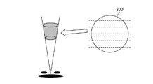
- FIG. 8 shows the concept of beam splitting corresponding to the frequency splitting unit 4 when splitting in the vertical direction.
- the beam 800 when viewed from the front is divided into six equal parts in the vertical direction as indicated by broken lines.
- the configuration of the radar apparatus is the same as that shown in the first embodiment or the second embodiment, except that angle measurement is performed in the vertical direction.
- the direction determined for each angle range obtained by dividing the angle determined by the beam widths of the plurality of antennas by the number of divided frequency ranges is the vertical direction.
- a resolution exceeding the resolution of the elevation angle determined by the beam width can be realized within the angle range and within the same distance range.
- Embodiment 4 the direction of angle measurement is performed in either the horizontal direction or the vertical direction.
- the radar apparatus has a function capable of measuring the angle in two dimensions
- the direction of the angle is determined in both directions.
- angle measurement processing may be performed, which will be described below as a fourth embodiment.
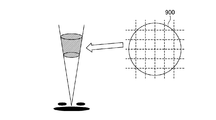
- FIG. 9 shows the concept of beam splitting corresponding to the frequency splitting unit 4 when splitting in both the horizontal and vertical directions.
- the beam 900 when viewed from the front is divided into six equal parts in the horizontal direction and the vertical direction as indicated by broken lines.
- the configuration of the radar apparatus is the same as that shown in the first embodiment or the second embodiment, except that angle measurement is performed in each of the horizontal direction and the vertical direction. With this configuration, the azimuth resolution is improved by the angle measurement in the horizontal direction, and the resolution of the elevation angle is improved by the angle measurement in the vertical direction.
- the direction for each angle range obtained by dividing the angle determined by the beam widths of the plurality of antennas by the number of divided frequency ranges is defined as the horizontal direction and the vertical direction. Therefore, when angle measurement processing is performed in both the horizontal direction and the vertical direction, a finer grid can be obtained within the same angle range and the same distance range by matching the wind direction and direction output for each direction. State output is possible.
- the radar apparatus relates to a radar apparatus having a resolution exceeding the angular resolution determined by the beam width, and is useful for estimating a sudden weather change such as a microburst or wind shear. It is.
- 1-1 to 1-n antenna 1-1 to 1-n antenna, 2 receiving unit, 3 pulse Doppler processing unit, 4 frequency division unit, 5 angle measurement processing unit, 6 output unit, 7 Doppler velocity width estimation unit, 8 Doppler velocity width comparison unit.
Landscapes
- Engineering & Computer Science (AREA)
- Radar, Positioning & Navigation (AREA)
- Remote Sensing (AREA)
- Physics & Mathematics (AREA)
- Computer Networks & Wireless Communication (AREA)
- General Physics & Mathematics (AREA)
- Electromagnetism (AREA)
- Radar Systems Or Details Thereof (AREA)
Abstract
Selon la présente invention, une unité de division de fréquence (4) divise une plage de fréquences de spectre Doppler émis par une unité de traitement Doppler pulsé (3) en une pluralité de plages de fréquences. Une unité de traitement de mesure d'angle (5) réalise un procédé de mesure d'angle pour chacune des plages de fréquences divisées à l'aide du spectre Doppler dans les mêmes plages de fréquences dans les plages de fréquences divisées. Une unité de sortie (6) délivre un résultat du traitement de mesure d'angle pour chacune des plages de fréquences divisées en tant que direction pour chaque plage d'angles qui est obtenue en divisant un angle déterminé par la largeur de faisceau d'antennes 1-1 à 1-n par le nombre de plages de fréquences divisées.
Priority Applications (1)
| Application Number | Priority Date | Filing Date | Title |
|---|---|---|---|
| PCT/JP2015/063087 WO2016178270A1 (fr) | 2015-05-01 | 2015-05-01 | Dispositif de radar |
Applications Claiming Priority (1)
| Application Number | Priority Date | Filing Date | Title |
|---|---|---|---|
| PCT/JP2015/063087 WO2016178270A1 (fr) | 2015-05-01 | 2015-05-01 | Dispositif de radar |
Publications (1)
| Publication Number | Publication Date |
|---|---|
| WO2016178270A1 true WO2016178270A1 (fr) | 2016-11-10 |
Family
ID=57218217
Family Applications (1)
| Application Number | Title | Priority Date | Filing Date |
|---|---|---|---|
| PCT/JP2015/063087 WO2016178270A1 (fr) | 2015-05-01 | 2015-05-01 | Dispositif de radar |
Country Status (1)
| Country | Link |
|---|---|
| WO (1) | WO2016178270A1 (fr) |
Cited By (1)
| Publication number | Priority date | Publication date | Assignee | Title |
|---|---|---|---|---|
| CN110658500A (zh) * | 2018-06-28 | 2020-01-07 | 立积电子股份有限公司 | 多普勒信号处理装置及信号处理方法 |
Citations (4)
| Publication number | Priority date | Publication date | Assignee | Title |
|---|---|---|---|---|
| JP2007147532A (ja) * | 2005-11-30 | 2007-06-14 | Hitachi Ltd | レーダ装置 |
| JP2009156807A (ja) * | 2007-12-27 | 2009-07-16 | Toshiba Corp | 測角装置 |
| JP2009300207A (ja) * | 2008-06-12 | 2009-12-24 | Nagano Japan Radio Co | 海洋レーダ局および海洋レーダ観測装置 |
| JP2010256333A (ja) * | 2009-04-02 | 2010-11-11 | Toshiba Corp | 気象レーダ装置及び気象観測方法 |
-
2015
- 2015-05-01 WO PCT/JP2015/063087 patent/WO2016178270A1/fr active Application Filing
Patent Citations (4)
| Publication number | Priority date | Publication date | Assignee | Title |
|---|---|---|---|---|
| JP2007147532A (ja) * | 2005-11-30 | 2007-06-14 | Hitachi Ltd | レーダ装置 |
| JP2009156807A (ja) * | 2007-12-27 | 2009-07-16 | Toshiba Corp | 測角装置 |
| JP2009300207A (ja) * | 2008-06-12 | 2009-12-24 | Nagano Japan Radio Co | 海洋レーダ局および海洋レーダ観測装置 |
| JP2010256333A (ja) * | 2009-04-02 | 2010-11-11 | Toshiba Corp | 気象レーダ装置及び気象観測方法 |
Cited By (2)
| Publication number | Priority date | Publication date | Assignee | Title |
|---|---|---|---|---|
| CN110658500A (zh) * | 2018-06-28 | 2020-01-07 | 立积电子股份有限公司 | 多普勒信号处理装置及信号处理方法 |
| CN110658500B (zh) * | 2018-06-28 | 2023-05-26 | 立积电子股份有限公司 | 多普勒信号处理装置及信号处理方法 |
Similar Documents
| Publication | Publication Date | Title |
|---|---|---|
| US10539645B2 (en) | Angle of arrival estimation | |
| JP6337030B2 (ja) | Massive−MIMOアンテナ測定装置およびその指向性測定方法 | |
| US20210278518A1 (en) | Novel automotive radar using 3d printed luneburg lens | |
| KR102013205B1 (ko) | 레이더 신호 처리 모의 장치 및 방법 | |
| CN109521426B (zh) | 基于汽车雷达获取目标的角度的方法及其装置 | |
| JP2016008852A (ja) | ドップラレーダ装置及びそのレーダ信号処理方法 | |
| KR101468548B1 (ko) | 레이더 장치 및 레이더 장치에서의 방위각 추정 방법 | |
| Ji et al. | Target monitoring using small-aperture compact high-frequency surface wave radar | |
| CN111665482A (zh) | 基于数字波束形成的目标分辨方法、存储介质及电子设备 | |
| KR102158740B1 (ko) | 레이다 DoA 추정 시스템 및 방법 | |
| WO2016178270A1 (fr) | Dispositif de radar | |
| JP6789671B2 (ja) | レーダ装置及びそのレーダ信号処理方法 | |
| JP2005189171A (ja) | レーダ装置 | |
| JP4784332B2 (ja) | パルスレーダ装置 | |
| CN113740823A (zh) | 适用于机载多通道合成孔径雷达的运动目标信号处理方法 | |
| KR101990078B1 (ko) | 레이더 신호 처리 모의 장치 | |
| Yamamoto et al. | Facility implementation of adaptive clutter suppression to an existing wind profiler radar: First result | |
| JP5501578B2 (ja) | レーダ装置 | |
| JP5047109B2 (ja) | レーダ装置 | |
| JP4867190B2 (ja) | レーダ装置及び測角方法 | |
| Lin et al. | Human tracking using a two-element antenna array | |
| JP2004251774A (ja) | レーダ装置 | |
| JP6415392B2 (ja) | 信号処理装置 | |
| Averyanova et al. | Simulations of multi polarization measurements and reflected signal magnitude variations caused by turbulence | |
| JP7412933B2 (ja) | レーダ装置 |
Legal Events
| Date | Code | Title | Description |
|---|---|---|---|
| 121 | Ep: the epo has been informed by wipo that ep was designated in this application |
Ref document number: 15891277 Country of ref document: EP Kind code of ref document: A1 |
|
| NENP | Non-entry into the national phase |
Ref country code: DE |
|
| 122 | Ep: pct application non-entry in european phase |
Ref document number: 15891277 Country of ref document: EP Kind code of ref document: A1 |
|
| NENP | Non-entry into the national phase |
Ref country code: JP |