WO2016178270A1 - Radar device - Google Patents
Radar device Download PDFInfo
- Publication number
- WO2016178270A1 WO2016178270A1 PCT/JP2015/063087 JP2015063087W WO2016178270A1 WO 2016178270 A1 WO2016178270 A1 WO 2016178270A1 JP 2015063087 W JP2015063087 W JP 2015063087W WO 2016178270 A1 WO2016178270 A1 WO 2016178270A1
- Authority
- WO
- WIPO (PCT)
- Prior art keywords
- doppler
- unit
- angle
- frequency range
- processing unit
- Prior art date
Links
Images

Classifications
-
- G—PHYSICS
- G01—MEASURING; TESTING
- G01S—RADIO DIRECTION-FINDING; RADIO NAVIGATION; DETERMINING DISTANCE OR VELOCITY BY USE OF RADIO WAVES; LOCATING OR PRESENCE-DETECTING BY USE OF THE REFLECTION OR RERADIATION OF RADIO WAVES; ANALOGOUS ARRANGEMENTS USING OTHER WAVES
- G01S13/00—Systems using the reflection or reradiation of radio waves, e.g. radar systems; Analogous systems using reflection or reradiation of waves whose nature or wavelength is irrelevant or unspecified
- G01S13/02—Systems using reflection of radio waves, e.g. primary radar systems; Analogous systems
- G01S13/06—Systems determining position data of a target
- G01S13/42—Simultaneous measurement of distance and other co-ordinates
-
- G—PHYSICS
- G01—MEASURING; TESTING
- G01S—RADIO DIRECTION-FINDING; RADIO NAVIGATION; DETERMINING DISTANCE OR VELOCITY BY USE OF RADIO WAVES; LOCATING OR PRESENCE-DETECTING BY USE OF THE REFLECTION OR RERADIATION OF RADIO WAVES; ANALOGOUS ARRANGEMENTS USING OTHER WAVES
- G01S13/00—Systems using the reflection or reradiation of radio waves, e.g. radar systems; Analogous systems using reflection or reradiation of waves whose nature or wavelength is irrelevant or unspecified
- G01S13/02—Systems using reflection of radio waves, e.g. primary radar systems; Analogous systems
- G01S13/50—Systems of measurement based on relative movement of target
- G01S13/52—Discriminating between fixed and moving objects or between objects moving at different speeds
- G01S13/522—Discriminating between fixed and moving objects or between objects moving at different speeds using transmissions of interrupted pulse modulated waves
- G01S13/524—Discriminating between fixed and moving objects or between objects moving at different speeds using transmissions of interrupted pulse modulated waves based upon the phase or frequency shift resulting from movement of objects, with reference to the transmitted signals, e.g. coherent MTi
-
- G—PHYSICS
- G01—MEASURING; TESTING
- G01S—RADIO DIRECTION-FINDING; RADIO NAVIGATION; DETERMINING DISTANCE OR VELOCITY BY USE OF RADIO WAVES; LOCATING OR PRESENCE-DETECTING BY USE OF THE REFLECTION OR RERADIATION OF RADIO WAVES; ANALOGOUS ARRANGEMENTS USING OTHER WAVES
- G01S13/00—Systems using the reflection or reradiation of radio waves, e.g. radar systems; Analogous systems using reflection or reradiation of waves whose nature or wavelength is irrelevant or unspecified
- G01S13/88—Radar or analogous systems specially adapted for specific applications
- G01S13/95—Radar or analogous systems specially adapted for specific applications for meteorological use
-
- Y—GENERAL TAGGING OF NEW TECHNOLOGICAL DEVELOPMENTS; GENERAL TAGGING OF CROSS-SECTIONAL TECHNOLOGIES SPANNING OVER SEVERAL SECTIONS OF THE IPC; TECHNICAL SUBJECTS COVERED BY FORMER USPC CROSS-REFERENCE ART COLLECTIONS [XRACs] AND DIGESTS
- Y02—TECHNOLOGIES OR APPLICATIONS FOR MITIGATION OR ADAPTATION AGAINST CLIMATE CHANGE
- Y02A—TECHNOLOGIES FOR ADAPTATION TO CLIMATE CHANGE
- Y02A90/00—Technologies having an indirect contribution to adaptation to climate change
- Y02A90/10—Information and communication technologies [ICT] supporting adaptation to climate change, e.g. for weather forecasting or climate simulation
Definitions
- the present invention relates to a radar apparatus having a resolution exceeding an angular resolution determined by a beam width using an array antenna capable of measuring an angle.
- weather radar detects the intensity of echoes reflected by rain particles such as clouds and rain, and uses the Doppler effect of reflected waves to detect dynamic changes in rain and clouds in order to observe or predict weather conditions.
- a pulse Doppler radar that can be captured is used.
- transmission pulses are repeatedly emitted at a required repetition interval. This pulse repetition period is determined by the maximum distance of the target to be detected.
- the minimum distance between two targets that can identify different targets in the same direction from the radar as two targets is determined by the transmission pulse width.
- the minimum azimuth difference between two targets that can identify different targets in the same distance from the radar as two targets is determined by the beam width of the antenna.
- weather radar assumes a uniform wind as a premise to blow within the same angle range and the same distance range, and observes the variation in the wind by the Doppler velocity width (for example, non-patent document). 1).
- the frequency spectrum of the received echo has a total shape in which a plurality of Gaussian distributions are overlapped, so that the Doppler velocity width is widened.
- the speed range is wide, it is estimated that the component moves variously, but it is still assumed that the premise is a uniform wind. Therefore, there has been a problem that the difference between the estimation result and the reality becomes large.
- the present invention has been made to solve such a problem, and an object of the present invention is to obtain a radar apparatus capable of realizing sufficient angular resolution even when a beam having a wide shape is used.
- a radar apparatus includes a pulse Doppler processing unit that performs pulse Doppler processing on each signal received by a plurality of antennas, and a frequency range of a Doppler spectrum output from the pulse Doppler processing unit.
- a frequency division unit that divides the frequency range, a doppler spectrum between the same frequency ranges in the divided frequency range, and an angle measurement processing unit that performs angle measurement processing for each divided frequency range, and for each divided frequency range
- an output unit that outputs the angle measurement processing result as a direction for each angle range obtained by dividing the angle determined by the beam widths of the plurality of antennas by the number of divisions of the frequency range.
- the radar apparatus divides the frequency range of the Doppler spectrum into a plurality of frequency ranges, and performs angle measurement processing for each divided frequency range using the Doppler spectra of the same frequency range in the divided frequency range. It is what I did. Thereby, even when a beam having a wide shape is used, sufficient angular resolution can be realized.
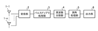
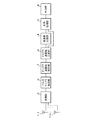
- FIG. 1 is a configuration diagram of a radar apparatus according to the present embodiment.
- the radar apparatus according to the present embodiment includes antennas 1-1 to 1-n, a receiving unit 2, a pulse Doppler processing unit 3, a frequency division unit 4, an angle measurement processing unit 5, and an output unit 6.
- Antennas 1-1 to 1-n are element antennas of an array antenna in which a plurality of element antennas are arranged as transmission antennas or reception antennas of a radar apparatus.
- the receiving unit 2 is a processing unit that acquires received signals from the antennas 1-1 to 1-n.
- the configuration of the transmission system in the radar apparatus is not directly related to the present invention, and thus illustration and description thereof are omitted.
- the pulse Doppler processing unit 3 is a processing unit that performs pulse Doppler processing on the two received signals from the receiving unit 2.
- the frequency dividing unit 4 divides the Doppler frequency range observable by the radar into a plurality of small ranges and proceeds to the next angle measurement process using only the data of each range, so that the output from the pulse Doppler processing unit 3
- the angle measurement processing unit 5 is a processing unit that performs angle measurement processing using signals in the same frequency range divided by the frequency division unit 4.
- the output unit 6 determines the direction for each angle range obtained by dividing the angle determined by the beam width of the antennas 1-1 to 1-n by the number of divisions in the frequency division unit 4 based on the angle measurement processing result in the angle measurement processing unit 5.
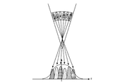
- FIG. 2 is an explanatory diagram showing the concept of angle measurement processing of the radar apparatus according to the first embodiment.
- the two antenna elements are divided into equal frequency ranges, and angle measurement processing is performed using the data of each range, thereby associating the spectrum and direction of each Gaussian distribution. it can. That is, it is possible to correlate from which part within the same distance range the wind having each divided Doppler frequency is.
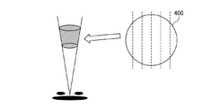
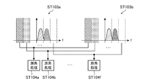
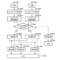
- FIG. 3 is an explanatory diagram illustrating the operation of the radar apparatus according to the first embodiment.
- Radio waves are transmitted from the two antennas 1-1 to 1-2, and reflected waves from the target are received by the receiving unit 2 (steps ST101a and ST101b), and each signal is subjected to pulse Doppler processing by the pulse Doppler processing unit 3.
- Steps ST102a and ST102b the pulse Doppler process is a process for obtaining the Doppler spectrum from the signal received by the receiving unit 2, and since this is known, a detailed description thereof is omitted here.
- the frequency dividing unit 4 divides the Doppler spectrum output from the pulse Doppler processing unit 3 into six frequency ranges, respectively (Steps ST103a and ST103b). Thereby, the spectrum of each Gaussian distribution is reproduced from the total spectrum in which a plurality of Gaussian distributions overlap. As shown in FIG. 4, this corresponds to dividing the beam 400 viewed from the front into six equal parts in the horizontal direction as shown by broken lines, that is, azimuthally divided into six parts.
- FIG. 5 is an explanatory diagram of frequency range division in the frequency division unit 4. As shown in FIG. 5, the Doppler spectrum from the frequency division unit 4 is divided into six frequency ranges, and two data in the same frequency range are output to the angle measurement processing unit 5.
- the angle measurement processing unit 5 performs angle measurement processing using Doppler spectra in the same frequency range of the six Doppler spectra output from the frequency division unit 4 (steps ST104a to ST104f). That is, the angle measurement processing unit 5 estimates the arrival direction of the incoming wave from which direction the signal is within the range of each of the six beam widths divided by the arrival direction estimation method.
- the arrival direction estimation method the output of each element antenna is multiplied by an appropriate complex weight. That is, by appropriately manipulating the amplitude and phase of the received signal of each element antenna, the directivity of the array antenna can be given to an arbitrary directivity.
- the received signal strength with each azimuth within the detection range as the directional azimuth is detected, and the directional azimuth at which the received signal strength peaks among the directional azimuths is estimated as the arrival azimuth of the incoming wave.
- the arrival direction of the incoming wave may be estimated with the NULL point of the directivity characteristic directed to an arbitrary direction.
- Various methods such as Beamformer method, Capon method and MUSIC (Multiple Signal Classification) method are known as arrival direction estimation methods. These arrival direction estimation methods are selected according to conditions and the like. By such angle measurement processing, the spectrum and direction of each Gaussian distribution can be associated.
- the output unit 6 associates the result of each angle measurement processing divided into 6 with which part of the divided Doppler frequency wind is within the same angle range and the same distance range. Output (step ST105).
- a pulse Doppler processing unit that performs pulse Doppler processing on each signal received by a plurality of antennas, and a Doppler output from the pulse Doppler processing unit.
- Angle measurement processing that performs angle measurement processing for each divided frequency range using a frequency division unit that divides the frequency range of the spectrum into a plurality of frequency ranges, and a Doppler spectrum between the same frequency ranges in the divided frequency ranges
- an output unit for outputting the angle measurement processing results for each divided frequency range as directions for each angle range obtained by dividing the angle determined by the beam widths of the plurality of antennas by the number of divided frequency ranges.
- the same angle range and the same distance range it can be further divided into multiple areas, which are determined by the beam width It is possible to realize a resolution exceeding the time resolution, for example, it is possible to realize a sufficient resolution even when performing estimation of sudden weather change such as a microburst or wind shear.
- the radar apparatus of the first embodiment since the direction for each angle range obtained by dividing the angle determined by the beam widths of the plurality of antennas by the number of divisions of the frequency range is the horizontal direction, Within the same distance range, it is possible to realize a resolution exceeding the resolution of the direction determined by the beam width. By improving the azimuth resolution, for example, the effect can be expected particularly when the wind direction changes in a layered manner with respect to the azimuth.
- Embodiment 2 the method is effective in a state where the spectrum width is wide.
- the spectrum width is narrow, there is a high possibility that the wind is uniform in the same angle range and the same distance range. In that case, it may not be effective to perform the processing of the first embodiment. Therefore, in the second embodiment, when the received signal obtained for each element antenna is subjected to pulse Doppler processing, if the Doppler velocity width is narrow, angle measurement processing is performed without dividing the range into a plurality of frequencies. It is.
- FIG. 6 is a block diagram showing the configuration of the radar apparatus according to Embodiment 2 of the present invention.
- the radar apparatus according to the second embodiment includes antennas 1-1 to 1-n, a receiving unit 2, a pulse Doppler processing unit 3, a frequency dividing unit 4, an angle measurement processing unit 5, an output unit 6, a Doppler velocity width estimation unit 7, A Doppler speed width comparison unit 8 is provided.
- the Doppler velocity width estimation unit 7 is a processing unit that estimates the frequency range of the Doppler spectrum processed by the pulse Doppler processing unit 3, that is, the Doppler velocity width, and the Doppler velocity width comparison unit 8 estimates the Doppler velocity width estimation unit 7. It is determined whether or not the Doppler velocity width is narrower than the set value.
- the Doppler spectrum in the pulse Doppler processing unit 3 is output to the angle measurement processing unit 5 as it is, and if it is greater than or equal to the set value , A processing unit that outputs to the frequency division unit 4. In addition, about a setting value, it selects suitably. Further, in FIG. 6, since each other configuration is the same as the configuration of the first embodiment shown in FIG. 1, the same reference numerals are given to the corresponding portions, and the description thereof is omitted.
- FIG. 7 is an explanatory diagram showing the operation of the radar apparatus according to the second embodiment.
- the reception operation steps ST101a and ST101b
- the pulse Doppler process steps ST102a and ST102b
- the Doppler velocity width estimation unit 7 estimates the frequency width (Doppler velocity width) of the Doppler spectrum output from the pulse Doppler processing unit 3 (Steps ST201a and ST201b), and compares the Doppler velocity widths.
- the unit 8 determines whether or not the frequency width is narrower than the set value (step ST202). In step ST202, if the frequency width is equal to or larger than the set value, the same operation as in the first embodiment is performed (steps ST103a, ST103b, steps ST104a to ST104f, step ST105).
- step ST202 if the frequency width of the Doppler spectrum is narrower than the set value in step ST202, the frequency division unit 4 does not perform frequency division, and the angle measurement processing unit 5 outputs the Doppler spectrum signal output from the pulse Doppler processing unit 3. Is used for angle measurement processing (step ST203).
- the output unit 6 outputs the result assuming that the azimuth obtained in step ST203 is the wind from any part within the angle determined by the beam width of the antennas 1-1 to 1-n (step ST204). ).
- the pulse Doppler processing unit that performs pulse Doppler processing on each signal received by a plurality of antennas, and the Doppler output from the pulse Doppler processing unit.
- the Doppler velocity width estimation unit for estimating the spectrum frequency range, the Doppler velocity width comparison unit for determining whether the frequency range estimated by the Doppler velocity width estimation unit is narrower than the set value, and the determination results of the Doppler velocity width comparison unit are If it is greater than or equal to the set value, the determination result of the frequency division unit that divides the frequency range of the Doppler spectrum output from the pulse Doppler processing unit into a plurality of frequency ranges and the Doppler velocity width comparison unit is greater than or equal to the set value.
- the frequency divided using the Doppler spectrum of the same frequency range in the divided frequency range Angle measurement processing is performed for each range, and if the determination result of the Doppler velocity width comparison unit is narrower than the set value, the angle measurement processing unit performs angle measurement processing using the Doppler spectrum output from the pulse Doppler processing unit, and the division Output the angle measurement processing results for each frequency range as the direction for each angle range obtained by dividing the angle determined by the beam widths of the plurality of antennas by the number of divisions of the frequency range.
- the resolution exceeding the angular resolution determined by the beam width can be realized while reducing the calculation load within and within the same distance range.
- Embodiment 3 In the first embodiment and the second embodiment, it is assumed that the angle is measured with respect to the horizontal direction of the received beam. However, the vertical direction is the same as in the first or second embodiment. Can be measured, and this will be described as a third embodiment.
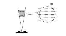
- FIG. 8 shows the concept of beam splitting corresponding to the frequency splitting unit 4 when splitting in the vertical direction.
- the beam 800 when viewed from the front is divided into six equal parts in the vertical direction as indicated by broken lines.
- the configuration of the radar apparatus is the same as that shown in the first embodiment or the second embodiment, except that angle measurement is performed in the vertical direction.
- the direction determined for each angle range obtained by dividing the angle determined by the beam widths of the plurality of antennas by the number of divided frequency ranges is the vertical direction.
- a resolution exceeding the resolution of the elevation angle determined by the beam width can be realized within the angle range and within the same distance range.
- Embodiment 4 the direction of angle measurement is performed in either the horizontal direction or the vertical direction.
- the radar apparatus has a function capable of measuring the angle in two dimensions
- the direction of the angle is determined in both directions.
- angle measurement processing may be performed, which will be described below as a fourth embodiment.
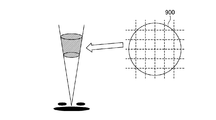
- FIG. 9 shows the concept of beam splitting corresponding to the frequency splitting unit 4 when splitting in both the horizontal and vertical directions.
- the beam 900 when viewed from the front is divided into six equal parts in the horizontal direction and the vertical direction as indicated by broken lines.
- the configuration of the radar apparatus is the same as that shown in the first embodiment or the second embodiment, except that angle measurement is performed in each of the horizontal direction and the vertical direction. With this configuration, the azimuth resolution is improved by the angle measurement in the horizontal direction, and the resolution of the elevation angle is improved by the angle measurement in the vertical direction.
- the direction for each angle range obtained by dividing the angle determined by the beam widths of the plurality of antennas by the number of divided frequency ranges is defined as the horizontal direction and the vertical direction. Therefore, when angle measurement processing is performed in both the horizontal direction and the vertical direction, a finer grid can be obtained within the same angle range and the same distance range by matching the wind direction and direction output for each direction. State output is possible.
- the radar apparatus relates to a radar apparatus having a resolution exceeding the angular resolution determined by the beam width, and is useful for estimating a sudden weather change such as a microburst or wind shear. It is.
- 1-1 to 1-n antenna 1-1 to 1-n antenna, 2 receiving unit, 3 pulse Doppler processing unit, 4 frequency division unit, 5 angle measurement processing unit, 6 output unit, 7 Doppler velocity width estimation unit, 8 Doppler velocity width comparison unit.
Landscapes
- Engineering & Computer Science (AREA)
- Radar, Positioning & Navigation (AREA)
- Remote Sensing (AREA)
- Physics & Mathematics (AREA)
- Computer Networks & Wireless Communication (AREA)
- General Physics & Mathematics (AREA)
- Electromagnetism (AREA)
- Radar Systems Or Details Thereof (AREA)
Abstract
According to the present invention, a frequency dividing unit 4 divides a frequency range of Doppler spectrum output by a pulse Doppler processing unit 3 into a plurality of frequency ranges. An angle measurement processing unit 5 performs an angle measurement process for each of the divided frequency ranges using the Doppler spectrum in the same frequency ranges in the divided frequency ranges. An outputting unit 6 outputs a result of the angle measurement process for each of the divided frequency ranges as a direction for each angle range that is obtained by dividing an angle determined by the beam width of antennas 1-1 to 1-n by the number of divided frequency ranges.
Description
この発明は、測角可能なアレーアンテナを用いて、ビーム幅によって決まる角度分解能を超えた分解能を有するレーダ装置に関するものである。
The present invention relates to a radar apparatus having a resolution exceeding an angular resolution determined by a beam width using an array antenna capable of measuring an angle.
例えば気象レーダでは、雲や雨の降雨粒子によって反射されるエコーの強さを検出し、気象状況を観測あるいは予測するため、反射波のドップラ効果を利用して雨や雲の動的な変化を捉えることができるパルスドップラレーダが用いられている。
For example, weather radar detects the intensity of echoes reflected by rain particles such as clouds and rain, and uses the Doppler effect of reflected waves to detect dynamic changes in rain and clouds in order to observe or predict weather conditions. A pulse Doppler radar that can be captured is used.
一般にパルスドップラレーダでは、送信パルスが所要の繰り返し間隔で繰り返し発射される。このパルス繰り返し周期は、探知しようとする目標の最大距離によって決定される。また、レーダから同一方向にある距離の異なる目標を、二つの目標として識別することができる2目標間の最小距離は、送信パルス幅によって決定される。さらに、レーダから同一距離にある方向の異なる目標を、二つの目標として識別することができる2目標間の最小方位差は、アンテナのビーム幅によって決定される。
Generally, in pulse Doppler radar, transmission pulses are repeatedly emitted at a required repetition interval. This pulse repetition period is determined by the maximum distance of the target to be detected. In addition, the minimum distance between two targets that can identify different targets in the same direction from the radar as two targets is determined by the transmission pulse width. Furthermore, the minimum azimuth difference between two targets that can identify different targets in the same distance from the radar as two targets is determined by the beam width of the antenna.
気象レーダでは、従来、同一角度範囲内及び同一距離範囲内に吹く風は前提として一様風を仮定し、その中での風のばらつきをドップラ速度幅により観測している(例えば、非特許文献1参照)。
Conventionally, weather radar assumes a uniform wind as a premise to blow within the same angle range and the same distance range, and observes the variation in the wind by the Doppler velocity width (for example, non-patent document). 1).
しかしながら、マイクロバーストやウインドシアなど急激に風向きが変わる現象では、同一角度範囲内及び同一距離範囲内で異なる風向きをもつ場合がある。この場合、受信エコーの周波数スペクトルは複数のガウス分布が重なり合った合計の形状をするためドップラ速度幅が広がる。速度幅が広い場合は、成分ごとに様々な動きをしていると評価するものの、依然、前提は一様風であるものと仮定している。従って、推定結果と現実との差が大きくなるという問題があった。
However, a phenomenon in which the wind direction changes suddenly, such as microburst or wind shear, may have different wind directions within the same angle range and within the same distance range. In this case, the frequency spectrum of the received echo has a total shape in which a plurality of Gaussian distributions are overlapped, so that the Doppler velocity width is widened. When the speed range is wide, it is estimated that the component moves variously, but it is still assumed that the premise is a uniform wind. Therefore, there has been a problem that the difference between the estimation result and the reality becomes large.
このような問題に対処するためには、より高い分解能を用いることで、この差異を減少させることができる。しかしながら、より高い角度分解能を得つつ測角精度を向上させるには、より幅の狭いビームを形成することが必要であり、そのためには十分な開口を有する空中線を必要とする。ところが、設置個所や運用の制限から、必ずしも十分な開口を有する空中線部を構成できるとは限らず、幅の広い形状のビームを用いざるを得ない場面においては、十分な角度分解能を得ることが困難であるという問題があった。
In order to deal with such problems, this difference can be reduced by using a higher resolution. However, in order to improve the angle measurement accuracy while obtaining a higher angular resolution, it is necessary to form a narrower beam, which requires an antenna having a sufficient aperture. However, it is not always possible to configure an aerial part having a sufficient opening due to installation location and operational restrictions, and in cases where a beam having a wide shape must be used, sufficient angular resolution can be obtained. There was a problem that it was difficult.
この発明は、かかる問題を解決するためになされたもので、幅の広い形状のビームを用いた場合にも、十分な角度分解能を実現することのできるレーダ装置を得ることを目的とする。
The present invention has been made to solve such a problem, and an object of the present invention is to obtain a radar apparatus capable of realizing sufficient angular resolution even when a beam having a wide shape is used.
この発明に係るレーダ装置は、複数のアンテナで受信したそれぞれの信号に対して、パルスドップラ処理を行うパルスドップラ処理部と、パルスドップラ処理部から出力されたドップラスペクトルの周波数範囲を、それぞれ複数の周波数範囲に分割する周波数分割部と、分割した周波数範囲における同一の周波数範囲同士のドップラスペクトルを用いて、分割した周波数範囲毎に測角処理を行う測角処理部と、分割した周波数範囲毎の測角処理結果を、複数のアンテナのビーム幅によって決定される角度を周波数範囲の分割個数で分割した角度範囲毎の方向として出力する出力部とを備えたものである。
A radar apparatus according to the present invention includes a pulse Doppler processing unit that performs pulse Doppler processing on each signal received by a plurality of antennas, and a frequency range of a Doppler spectrum output from the pulse Doppler processing unit. A frequency division unit that divides the frequency range, a doppler spectrum between the same frequency ranges in the divided frequency range, and an angle measurement processing unit that performs angle measurement processing for each divided frequency range, and for each divided frequency range And an output unit that outputs the angle measurement processing result as a direction for each angle range obtained by dividing the angle determined by the beam widths of the plurality of antennas by the number of divisions of the frequency range.
この発明に係るレーダ装置は、ドップラスペクトルの周波数範囲を複数の周波数範囲に分割し、分割した周波数範囲における同一の周波数範囲同士のドップラスペクトルを用いて、分割した周波数範囲毎に測角処理を行うようにしたものである。これにより、幅の広い形状のビームを用いた場合にも、十分な角度分解能を実現することができる。
The radar apparatus according to the present invention divides the frequency range of the Doppler spectrum into a plurality of frequency ranges, and performs angle measurement processing for each divided frequency range using the Doppler spectra of the same frequency range in the divided frequency range. It is what I did. Thereby, even when a beam having a wide shape is used, sufficient angular resolution can be realized.
以下、この発明をより詳細に説明するために、この発明を実施するための形態について、添付の図面に従って説明する。
実施の形態1.
図1は、本実施の形態によるレーダ装置の構成図である。
本実施の形態によるレーダ装置は、図1に示すように、アンテナ1-1~1-n、受信部2、パルスドップラ処理部3、周波数分割部4、測角処理部5、出力部6を備えている。アンテナ1-1~1-nは、レーダ装置の送信アンテナまたは受信アンテナとして複数の素子アンテナを配列したアレイアンテナの素子アンテナである。本実施の形態では、説明を簡単にするため、アレーアンテナが2個の素子アンテナからなるとして以下の説明を行う。受信部2は、アンテナ1-1~1-nからの受信信号を取得する処理部である。なお、レーダ装置における送信系の構成については本発明では直接関係がないため、その図示及び説明を省略する。パルスドップラ処理部3は、受信部2からの二つの受信信号に対してそれぞれパルスドップラ処理を行う処理部である。周波数分割部4は、レーダで観測可能なドップラ周波数の範囲を複数の小範囲に分割し、各範囲のみのデータを用いてそれぞれ次の測角処理に進めるため、パルスドップラ処理部3からの出力信号を複数の周波数範囲に分割する処理部である。本実施の形態では6分割する例で説明する。測角処理部5は、周波数分割部4で分割された同じ周波数範囲同士の信号を用いて測角処理を行う処理部である。出力部6は、測角処理部5における測角処理結果により、アンテナ1-1~1-nのビーム幅によって決定される角度を周波数分割部4での分割個数で分割した角度範囲毎の方向として出力する処理部である。 Hereinafter, in order to explain the present invention in more detail, modes for carrying out the present invention will be described with reference to the accompanying drawings.
Embodiment 1 FIG.
FIG. 1 is a configuration diagram of a radar apparatus according to the present embodiment.
As shown in FIG. 1, the radar apparatus according to the present embodiment includes antennas 1-1 to 1-n, a receiving unit 2, a pulse Doppler processing unit 3, afrequency division unit 4, an angle measurement processing unit 5, and an output unit 6. I have. Antennas 1-1 to 1-n are element antennas of an array antenna in which a plurality of element antennas are arranged as transmission antennas or reception antennas of a radar apparatus. In the present embodiment, in order to simplify the description, the following description will be made assuming that the array antenna is composed of two element antennas. The receiving unit 2 is a processing unit that acquires received signals from the antennas 1-1 to 1-n. The configuration of the transmission system in the radar apparatus is not directly related to the present invention, and thus illustration and description thereof are omitted. The pulse Doppler processing unit 3 is a processing unit that performs pulse Doppler processing on the two received signals from the receiving unit 2. The frequency dividing unit 4 divides the Doppler frequency range observable by the radar into a plurality of small ranges and proceeds to the next angle measurement process using only the data of each range, so that the output from the pulse Doppler processing unit 3 A processing unit that divides the signal into a plurality of frequency ranges. In this embodiment, an example of dividing into six parts will be described. The angle measurement processing unit 5 is a processing unit that performs angle measurement processing using signals in the same frequency range divided by the frequency division unit 4. The output unit 6 determines the direction for each angle range obtained by dividing the angle determined by the beam width of the antennas 1-1 to 1-n by the number of divisions in the frequency division unit 4 based on the angle measurement processing result in the angle measurement processing unit 5. As a processing unit that outputs as
実施の形態1.
図1は、本実施の形態によるレーダ装置の構成図である。
本実施の形態によるレーダ装置は、図1に示すように、アンテナ1-1~1-n、受信部2、パルスドップラ処理部3、周波数分割部4、測角処理部5、出力部6を備えている。アンテナ1-1~1-nは、レーダ装置の送信アンテナまたは受信アンテナとして複数の素子アンテナを配列したアレイアンテナの素子アンテナである。本実施の形態では、説明を簡単にするため、アレーアンテナが2個の素子アンテナからなるとして以下の説明を行う。受信部2は、アンテナ1-1~1-nからの受信信号を取得する処理部である。なお、レーダ装置における送信系の構成については本発明では直接関係がないため、その図示及び説明を省略する。パルスドップラ処理部3は、受信部2からの二つの受信信号に対してそれぞれパルスドップラ処理を行う処理部である。周波数分割部4は、レーダで観測可能なドップラ周波数の範囲を複数の小範囲に分割し、各範囲のみのデータを用いてそれぞれ次の測角処理に進めるため、パルスドップラ処理部3からの出力信号を複数の周波数範囲に分割する処理部である。本実施の形態では6分割する例で説明する。測角処理部5は、周波数分割部4で分割された同じ周波数範囲同士の信号を用いて測角処理を行う処理部である。出力部6は、測角処理部5における測角処理結果により、アンテナ1-1~1-nのビーム幅によって決定される角度を周波数分割部4での分割個数で分割した角度範囲毎の方向として出力する処理部である。 Hereinafter, in order to explain the present invention in more detail, modes for carrying out the present invention will be described with reference to the accompanying drawings.
FIG. 1 is a configuration diagram of a radar apparatus according to the present embodiment.
As shown in FIG. 1, the radar apparatus according to the present embodiment includes antennas 1-1 to 1-n, a receiving unit 2, a pulse Doppler processing unit 3, a
図2は、実施の形態1のレーダ装置の測角処理の概念を示す説明図である。実施の形態1では、二つのアンテナ素子に対して、等しい周波数の範囲の分割を行い、各範囲のデータを用いて測角処理を行うことにより、各ガウス分布のスペクトルと方向とを関連づけることができる。つまり、分割した各ドップラ周波数を持つ風が同一距離範囲内のどの部分からの風であるかを関連づけることができる。
FIG. 2 is an explanatory diagram showing the concept of angle measurement processing of the radar apparatus according to the first embodiment. In the first embodiment, the two antenna elements are divided into equal frequency ranges, and angle measurement processing is performed using the data of each range, thereby associating the spectrum and direction of each Gaussian distribution. it can. That is, it is possible to correlate from which part within the same distance range the wind having each divided Doppler frequency is.
次に、実施の形態1のレーダ装置の動作について説明する。
図3は、実施の形態1のレーダ装置の動作を示す説明図である。
2本のアンテナ1-1~1-2から電波を送信して目標からの反射波を受信部2で受信し(ステップST101a,ST101b)、それぞれの信号をパルスドップラ処理部3でパルスドップラ処理する(ステップST102a,ST102b)。ここで、パルスドップラ処理とは、受信部2で受信した信号からそのドップラスペクトルを求める処理であるが、これについては公知であるため、ここでの詳細な説明は省略する。次に、周波数分割部4は、パルスドップラ処理部3から出力されたドップラスペクトルをそれぞれ6個の周波数範囲で分割する(ステップST103a,ST103b)。これにより、複数のガウス分布が重なり合った合計のスペクトルから、各ガウス分布のスペクトルを再現させている。これは、図4に示すように、正面から見たビーム400を破線で示すように水平方向に6等分、すなわち、方位を6等分したことに相当する。また、図5は周波数分割部4における周波数範囲分割の説明図である。図5に示すように、周波数分割部4からのドップラスペクトルをそれぞれ6個の周波数範囲に分割し、同一周波数範囲の二つのデータを測角処理部5に出力する。 Next, the operation of the radar apparatus according to the first embodiment will be described.
FIG. 3 is an explanatory diagram illustrating the operation of the radar apparatus according to the first embodiment.
Radio waves are transmitted from the two antennas 1-1 to 1-2, and reflected waves from the target are received by the receiving unit 2 (steps ST101a and ST101b), and each signal is subjected to pulse Doppler processing by the pulse Doppler processing unit 3. (Steps ST102a and ST102b). Here, the pulse Doppler process is a process for obtaining the Doppler spectrum from the signal received by the receiving unit 2, and since this is known, a detailed description thereof is omitted here. Next, thefrequency dividing unit 4 divides the Doppler spectrum output from the pulse Doppler processing unit 3 into six frequency ranges, respectively (Steps ST103a and ST103b). Thereby, the spectrum of each Gaussian distribution is reproduced from the total spectrum in which a plurality of Gaussian distributions overlap. As shown in FIG. 4, this corresponds to dividing the beam 400 viewed from the front into six equal parts in the horizontal direction as shown by broken lines, that is, azimuthally divided into six parts. FIG. 5 is an explanatory diagram of frequency range division in the frequency division unit 4. As shown in FIG. 5, the Doppler spectrum from the frequency division unit 4 is divided into six frequency ranges, and two data in the same frequency range are output to the angle measurement processing unit 5.
図3は、実施の形態1のレーダ装置の動作を示す説明図である。
2本のアンテナ1-1~1-2から電波を送信して目標からの反射波を受信部2で受信し(ステップST101a,ST101b)、それぞれの信号をパルスドップラ処理部3でパルスドップラ処理する(ステップST102a,ST102b)。ここで、パルスドップラ処理とは、受信部2で受信した信号からそのドップラスペクトルを求める処理であるが、これについては公知であるため、ここでの詳細な説明は省略する。次に、周波数分割部4は、パルスドップラ処理部3から出力されたドップラスペクトルをそれぞれ6個の周波数範囲で分割する(ステップST103a,ST103b)。これにより、複数のガウス分布が重なり合った合計のスペクトルから、各ガウス分布のスペクトルを再現させている。これは、図4に示すように、正面から見たビーム400を破線で示すように水平方向に6等分、すなわち、方位を6等分したことに相当する。また、図5は周波数分割部4における周波数範囲分割の説明図である。図5に示すように、周波数分割部4からのドップラスペクトルをそれぞれ6個の周波数範囲に分割し、同一周波数範囲の二つのデータを測角処理部5に出力する。 Next, the operation of the radar apparatus according to the first embodiment will be described.
FIG. 3 is an explanatory diagram illustrating the operation of the radar apparatus according to the first embodiment.
Radio waves are transmitted from the two antennas 1-1 to 1-2, and reflected waves from the target are received by the receiving unit 2 (steps ST101a and ST101b), and each signal is subjected to pulse Doppler processing by the pulse Doppler processing unit 3. (Steps ST102a and ST102b). Here, the pulse Doppler process is a process for obtaining the Doppler spectrum from the signal received by the receiving unit 2, and since this is known, a detailed description thereof is omitted here. Next, the
測角処理部5は、周波数分割部4から出力された6個のドップラスペクトルの同じ周波数範囲のドップラスペクトル同士を用いて測角処理を行う(ステップST104a~ST104f)。すなわち、測角処理部5は、到来方位推定法により、6分割したそれぞれのビーム幅の範囲内でどの方位からの信号であるか、到来波の到来方位を推定する。ここで、到来方位推定法では、各素子アンテナの出力に適当な複素数の重みを乗算する。すなわち各素子アンテナの受信信号の振幅と位相をそれぞれ適切に操作することによって、任意の指向方位にアレーアンテナの指向性をもたせる。このようにして探知範囲内の各方位を指向方位とした受信信号強度を検出し、各指向方位のうち受信信号強度がピークとなる指向方位を到来波の到来方位として推定する。また、指向特性のNULL点を任意の方位に向け到来波の到来方位を推定することもある。到来方位推定法としては、Beamformer法やCapon法やMUSIC(MUltiple SIgnal Classification)法など様々なものが知られている。これら到来方位推定法は条件等に応じて選択する。このような測角処理により、各ガウス分布のスペクトルと方向を関連づけることができる。
The angle measurement processing unit 5 performs angle measurement processing using Doppler spectra in the same frequency range of the six Doppler spectra output from the frequency division unit 4 (steps ST104a to ST104f). That is, the angle measurement processing unit 5 estimates the arrival direction of the incoming wave from which direction the signal is within the range of each of the six beam widths divided by the arrival direction estimation method. Here, in the arrival direction estimation method, the output of each element antenna is multiplied by an appropriate complex weight. That is, by appropriately manipulating the amplitude and phase of the received signal of each element antenna, the directivity of the array antenna can be given to an arbitrary directivity. In this way, the received signal strength with each azimuth within the detection range as the directional azimuth is detected, and the directional azimuth at which the received signal strength peaks among the directional azimuths is estimated as the arrival azimuth of the incoming wave. Further, the arrival direction of the incoming wave may be estimated with the NULL point of the directivity characteristic directed to an arbitrary direction. Various methods such as Beamformer method, Capon method and MUSIC (Multiple Signal Classification) method are known as arrival direction estimation methods. These arrival direction estimation methods are selected according to conditions and the like. By such angle measurement processing, the spectrum and direction of each Gaussian distribution can be associated.
出力部6は、6分割されたそれぞれの測角処理結果に基づき、分割した各ドップラ周波数を持つ風が同一角度範囲内及び同一距離範囲内のどの部分からの風であるかを関連づけて結果を出力する(ステップST105)。
The output unit 6 associates the result of each angle measurement processing divided into 6 with which part of the divided Doppler frequency wind is within the same angle range and the same distance range. Output (step ST105).
以上説明したように、実施の形態1のレーダ装置によれば、複数のアンテナで受信したそれぞれの信号に対して、パルスドップラ処理を行うパルスドップラ処理部と、パルスドップラ処理部から出力されたドップラスペクトルの周波数範囲を、それぞれ複数の周波数範囲に分割する周波数分割部と、分割した周波数範囲における同一の周波数範囲同士のドップラスペクトルを用いて、分割した周波数範囲毎に測角処理を行う測角処理部と、分割した周波数範囲毎の測角処理結果を、複数のアンテナのビーム幅によって決定される角度を周波数範囲の分割個数で分割した角度範囲毎の方向として出力する出力部とを備えたので、同一角度範囲内及び同一距離範囲内において、さらに複数のエリアに分けることができ、ビーム幅によって決まる角度分解能を超えた分解能を実現することが可能となり、例えば、マイクロバーストやウインドシアなどの急激な気象変化の推定を行う際にも十分な分解能を実現することができる。
As described above, according to the radar apparatus of the first embodiment, a pulse Doppler processing unit that performs pulse Doppler processing on each signal received by a plurality of antennas, and a Doppler output from the pulse Doppler processing unit. Angle measurement processing that performs angle measurement processing for each divided frequency range using a frequency division unit that divides the frequency range of the spectrum into a plurality of frequency ranges, and a Doppler spectrum between the same frequency ranges in the divided frequency ranges And an output unit for outputting the angle measurement processing results for each divided frequency range as directions for each angle range obtained by dividing the angle determined by the beam widths of the plurality of antennas by the number of divided frequency ranges. In the same angle range and the same distance range, it can be further divided into multiple areas, which are determined by the beam width It is possible to realize a resolution exceeding the time resolution, for example, it is possible to realize a sufficient resolution even when performing estimation of sudden weather change such as a microburst or wind shear.
また、実施の形態1のレーダ装置によれば、複数のアンテナのビーム幅によって決定される角度を周波数範囲の分割個数で分割した角度範囲毎の方向を水平方向としたので、同一角度範囲内及び同一距離範囲内において、ビーム幅によって決まる方位の分解能を超えた分解能を実現することが可能となる。方位の分解能が向上することで、例えば、方位に対して層状に風向きが変わる場合に特に効果が期待できる。
Further, according to the radar apparatus of the first embodiment, since the direction for each angle range obtained by dividing the angle determined by the beam widths of the plurality of antennas by the number of divisions of the frequency range is the horizontal direction, Within the same distance range, it is possible to realize a resolution exceeding the resolution of the direction determined by the beam width. By improving the azimuth resolution, for example, the effect can be expected particularly when the wind direction changes in a layered manner with respect to the azimuth.
実施の形態2.
上記実施の形態1では、スペクトル幅が広い状態に効果のある方法であるが、スペクトル幅が狭い場合、同一角度範囲内及び同一距離範囲内にふく風が一様風である可能性が高く、その場合、実施の形態1の処理を行うのは有効でないことがある。そこで、実施の形態2では、素子アンテナ毎に得られた受信信号をそれぞれパルスドップラ処理した際、ドップラ速度幅が狭ければ複数の周波数の範囲に分けることなく測角処理を行うようにしたものである。 Embodiment 2. FIG.
In the first embodiment, the method is effective in a state where the spectrum width is wide. However, when the spectrum width is narrow, there is a high possibility that the wind is uniform in the same angle range and the same distance range. In that case, it may not be effective to perform the processing of the first embodiment. Therefore, in the second embodiment, when the received signal obtained for each element antenna is subjected to pulse Doppler processing, if the Doppler velocity width is narrow, angle measurement processing is performed without dividing the range into a plurality of frequencies. It is.
図6は、この発明の実施の形態2のレーダ装置の構成を示すブロック図である。実施の形態2のレーダ装置は、アンテナ1-1~1-n、受信部2、パルスドップラ処理部3、周波数分割部4、測角処理部5、出力部6、ドップラ速度幅推定部7、ドップラ速度幅比較部8を備えている。ドップラ速度幅推定部7は、パルスドップラ処理部3で処理されたドップラスペクトルの周波数範囲すなわちドップラ速度幅を推定する処理部であり、ドップラ速度幅比較部8は、ドップラ速度幅推定部7で推定されたドップラ速度幅が設定値より狭いか否かを判定し、狭かった場合は、パルスドップラ処理部3でのドップラスペクトルをそのまま測角処理部5に出力し、設定値以上であった場合は、周波数分割部4に出力する処理部である。なお、設定値については、適宜選択する。また、図6において、他の各構成は、図1に示した実施の形態1の構成と同様であるため、対応する部分に同一符号を付してその説明を省略する。
FIG. 6 is a block diagram showing the configuration of the radar apparatus according to Embodiment 2 of the present invention. The radar apparatus according to the second embodiment includes antennas 1-1 to 1-n, a receiving unit 2, a pulse Doppler processing unit 3, a frequency dividing unit 4, an angle measurement processing unit 5, an output unit 6, a Doppler velocity width estimation unit 7, A Doppler speed width comparison unit 8 is provided. The Doppler velocity width estimation unit 7 is a processing unit that estimates the frequency range of the Doppler spectrum processed by the pulse Doppler processing unit 3, that is, the Doppler velocity width, and the Doppler velocity width comparison unit 8 estimates the Doppler velocity width estimation unit 7. It is determined whether or not the Doppler velocity width is narrower than the set value. If it is narrow, the Doppler spectrum in the pulse Doppler processing unit 3 is output to the angle measurement processing unit 5 as it is, and if it is greater than or equal to the set value , A processing unit that outputs to the frequency division unit 4. In addition, about a setting value, it selects suitably. Further, in FIG. 6, since each other configuration is the same as the configuration of the first embodiment shown in FIG. 1, the same reference numerals are given to the corresponding portions, and the description thereof is omitted.
次に、実施の形態2のレーダ装置の動作について説明する。
図7は、実施の形態2のレーダ装置の動作を示す説明図である。
先ず、受信動作(ステップST101a,ST101b)及びパルスドップラ処理(ステップST102a,ST102b)は、実施の形態1と同様である。次に、実施の形態2では、ドップラ速度幅推定部7が、パルスドップラ処理部3から出力されたドップラスペクトルの周波数幅(ドップラ速度幅)を推定し(ステップST201a,ST201b)、ドップラ速度幅比較部8が、その周波数幅が設定値より狭いか否かを判定する(ステップST202)。このステップST202において、周波数幅が設定値以上であった場合は、実施の形態1と同様の動作を行う(ステップST103a,ST103b、ステップST104a~ST104f、ステップST105)。 Next, the operation of the radar apparatus according to the second embodiment will be described.
FIG. 7 is an explanatory diagram showing the operation of the radar apparatus according to the second embodiment.
First, the reception operation (steps ST101a and ST101b) and the pulse Doppler process (steps ST102a and ST102b) are the same as those in the first embodiment. Next, in the second embodiment, the Doppler velocity width estimation unit 7 estimates the frequency width (Doppler velocity width) of the Doppler spectrum output from the pulse Doppler processing unit 3 (Steps ST201a and ST201b), and compares the Doppler velocity widths. Theunit 8 determines whether or not the frequency width is narrower than the set value (step ST202). In step ST202, if the frequency width is equal to or larger than the set value, the same operation as in the first embodiment is performed (steps ST103a, ST103b, steps ST104a to ST104f, step ST105).
図7は、実施の形態2のレーダ装置の動作を示す説明図である。
先ず、受信動作(ステップST101a,ST101b)及びパルスドップラ処理(ステップST102a,ST102b)は、実施の形態1と同様である。次に、実施の形態2では、ドップラ速度幅推定部7が、パルスドップラ処理部3から出力されたドップラスペクトルの周波数幅(ドップラ速度幅)を推定し(ステップST201a,ST201b)、ドップラ速度幅比較部8が、その周波数幅が設定値より狭いか否かを判定する(ステップST202)。このステップST202において、周波数幅が設定値以上であった場合は、実施の形態1と同様の動作を行う(ステップST103a,ST103b、ステップST104a~ST104f、ステップST105)。 Next, the operation of the radar apparatus according to the second embodiment will be described.
FIG. 7 is an explanatory diagram showing the operation of the radar apparatus according to the second embodiment.
First, the reception operation (steps ST101a and ST101b) and the pulse Doppler process (steps ST102a and ST102b) are the same as those in the first embodiment. Next, in the second embodiment, the Doppler velocity width estimation unit 7 estimates the frequency width (Doppler velocity width) of the Doppler spectrum output from the pulse Doppler processing unit 3 (Steps ST201a and ST201b), and compares the Doppler velocity widths. The
一方、ステップST202において、ドップラスペクトルの周波数幅が設定値より狭かった場合は、周波数分割部4による周波数分割はせず、測角処理部5はパルスドップラ処理部3から出力されたドップラスペクトルの信号をそのまま用いて測角処理を行う(ステップST203)。次に、出力部6は、ステップST203で求められた方位を、アンテナ1-1~1-nのビーム幅によって決定される角度内のどの部分からの風であるとして結果を出力する(ステップST204)。
On the other hand, if the frequency width of the Doppler spectrum is narrower than the set value in step ST202, the frequency division unit 4 does not perform frequency division, and the angle measurement processing unit 5 outputs the Doppler spectrum signal output from the pulse Doppler processing unit 3. Is used for angle measurement processing (step ST203). Next, the output unit 6 outputs the result assuming that the azimuth obtained in step ST203 is the wind from any part within the angle determined by the beam width of the antennas 1-1 to 1-n (step ST204). ).
以上説明したように、実施の形態2のレーダ装置によれば、複数のアンテナで受信したそれぞれの信号に対して、パルスドップラ処理を行うパルスドップラ処理部と、パルスドップラ処理部から出力されたドップラスペクトルの周波数範囲を推定するドップラ速度幅推定部と、ドップラ速度幅推定部で推定された周波数範囲が設定値より狭いかを判定するドップラ速度幅比較部と、ドップラ速度幅比較部の判定結果が設定値以上であった場合は、パルスドップラ処理部から出力されたドップラスペクトルの周波数範囲を、それぞれ複数の周波数範囲に分割する周波数分割部と、ドップラ速度幅比較部の判定結果が設定値以上であった場合は、分割した周波数範囲における同一の周波数範囲同士のドップラスペクトルを用いて分割した周波数範囲毎に測角処理を行い、ドップラ速度幅比較部の判定結果が設定値より狭かった場合はパルスドップラ処理部から出力されたドップラスペクトルを用いて測角処理を行う測角処理部と、分割した周波数範囲毎の測角処理結果を、複数のアンテナのビーム幅によって決定される角度を周波数範囲の分割個数で分割した角度範囲毎の方向として出力する出力部とを備えたので、同一角度範囲内及び同一距離範囲内において、計算負荷を減らしながら、ビーム幅によって決まる角度分解能を超えた分解能を実現することができる。
As described above, according to the radar apparatus of the second embodiment, the pulse Doppler processing unit that performs pulse Doppler processing on each signal received by a plurality of antennas, and the Doppler output from the pulse Doppler processing unit. The Doppler velocity width estimation unit for estimating the spectrum frequency range, the Doppler velocity width comparison unit for determining whether the frequency range estimated by the Doppler velocity width estimation unit is narrower than the set value, and the determination results of the Doppler velocity width comparison unit are If it is greater than or equal to the set value, the determination result of the frequency division unit that divides the frequency range of the Doppler spectrum output from the pulse Doppler processing unit into a plurality of frequency ranges and the Doppler velocity width comparison unit is greater than or equal to the set value. If so, the frequency divided using the Doppler spectrum of the same frequency range in the divided frequency range Angle measurement processing is performed for each range, and if the determination result of the Doppler velocity width comparison unit is narrower than the set value, the angle measurement processing unit performs angle measurement processing using the Doppler spectrum output from the pulse Doppler processing unit, and the division Output the angle measurement processing results for each frequency range as the direction for each angle range obtained by dividing the angle determined by the beam widths of the plurality of antennas by the number of divisions of the frequency range. The resolution exceeding the angular resolution determined by the beam width can be realized while reducing the calculation load within and within the same distance range.
実施の形態3.
上記実施の形態1及び実施の形態2では、受信ビームの水平方向に対して測角を行ったものを想定しているが、垂直方向に対して、実施の形態1または実施の形態2と同様の測角を行うことができ、これを実施の形態3として説明する。 Embodiment 3 FIG.
In the first embodiment and the second embodiment, it is assumed that the angle is measured with respect to the horizontal direction of the received beam. However, the vertical direction is the same as in the first or second embodiment. Can be measured, and this will be described as a third embodiment.
水平方面からの推定ではビームを縦長に範囲分けすることになるが、垂直方面からの推定では、ビームを横長に範囲分けすることになる。つまり、垂直方向に測角を行った場合、方位分解能は従来と変わらないが、仰角の分解能が向上する。図8に、垂直方向に分割した場合の周波数分割部4に対応するビーム分割の概念を示す。図示のように、正面から見たときのビーム800を破線で示すように垂直方向に6等分する。レーダ装置としての構成は、実施の形態1または実施の形態2で示したものと同様であるが、垂直方向に測角を行う点が異なっている。
In the estimation from the horizontal direction, the beam is divided into a vertically long range, but in the estimation from the vertical direction, the beam is divided into a horizontally long range. That is, when the angle is measured in the vertical direction, the azimuth resolution is not different from the conventional one, but the resolution of the elevation angle is improved. FIG. 8 shows the concept of beam splitting corresponding to the frequency splitting unit 4 when splitting in the vertical direction. As shown in the figure, the beam 800 when viewed from the front is divided into six equal parts in the vertical direction as indicated by broken lines. The configuration of the radar apparatus is the same as that shown in the first embodiment or the second embodiment, except that angle measurement is performed in the vertical direction.
以上説明したように、実施の形態3のレーダ装置によれば、複数のアンテナのビーム幅によって決定される角度を周波数範囲の分割個数で分割した角度範囲毎の方向を垂直方向としたので、同一角度範囲内及び同一距離範囲内において、ビーム幅によって決まる仰角の分解能を超えた分解能を実現することができる。仰角の分解能が向上することで、例えば、高度に対して層状に風向きが変わる場合に特に効果が期待できる。
As described above, according to the radar apparatus of the third embodiment, the direction determined for each angle range obtained by dividing the angle determined by the beam widths of the plurality of antennas by the number of divided frequency ranges is the vertical direction. A resolution exceeding the resolution of the elevation angle determined by the beam width can be realized within the angle range and within the same distance range. By improving the resolution of the elevation angle, for example, an effect can be expected particularly when the wind direction changes in layers with respect to altitude.
実施の形態4.
上記実施の形態1~3では、測角の方向を水平方向または垂直方向のいずれかに対して行っていたが、レーダ装置が2次元に対して測角できる機能をもつ場合、両方の方向に対して測角処理を行うようにしてもよく、これを実施の形態4として以下説明する。Embodiment 4 FIG.
In the first to third embodiments, the direction of angle measurement is performed in either the horizontal direction or the vertical direction. However, when the radar apparatus has a function capable of measuring the angle in two dimensions, the direction of the angle is determined in both directions. On the other hand, angle measurement processing may be performed, which will be described below as a fourth embodiment.
上記実施の形態1~3では、測角の方向を水平方向または垂直方向のいずれかに対して行っていたが、レーダ装置が2次元に対して測角できる機能をもつ場合、両方の方向に対して測角処理を行うようにしてもよく、これを実施の形態4として以下説明する。
In the first to third embodiments, the direction of angle measurement is performed in either the horizontal direction or the vertical direction. However, when the radar apparatus has a function capable of measuring the angle in two dimensions, the direction of the angle is determined in both directions. On the other hand, angle measurement processing may be performed, which will be described below as a fourth embodiment.
図9に、水平方向と垂直方向共に分割した場合の周波数分割部4に対応するビーム分割の概念を示す。図示のように、正面から見たときのビーム900を破線で示すように水平方向と垂直方向にそれぞれ6等分する。レーダ装置としての構成は、実施の形態1または実施の形態2で示したものと同様であるが、水平方向と垂直方向のそれぞれに測角を行う点が異なっている。このように構成することにより、水平方向での測角で方位分解能が向上し、垂直方向での測角で仰角の分解能が向上する。
FIG. 9 shows the concept of beam splitting corresponding to the frequency splitting unit 4 when splitting in both the horizontal and vertical directions. As shown in the figure, the beam 900 when viewed from the front is divided into six equal parts in the horizontal direction and the vertical direction as indicated by broken lines. The configuration of the radar apparatus is the same as that shown in the first embodiment or the second embodiment, except that angle measurement is performed in each of the horizontal direction and the vertical direction. With this configuration, the azimuth resolution is improved by the angle measurement in the horizontal direction, and the resolution of the elevation angle is improved by the angle measurement in the vertical direction.
以上説明したように、実施の形態4のレーダ装置によれば、複数のアンテナのビーム幅によって決定される角度を周波数範囲の分割個数で分割した角度範囲毎の方向を水平方向と垂直方向としたので、水平方向と垂直方向の両方に対して測角処理を行った場合、各方向に対して出力された風向きと方向を合わせることで、同一角度範囲内及び同一距離範囲内において、より細かい格子状の範囲出力が可能となる。
As described above, according to the radar apparatus of the fourth embodiment, the direction for each angle range obtained by dividing the angle determined by the beam widths of the plurality of antennas by the number of divided frequency ranges is defined as the horizontal direction and the vertical direction. Therefore, when angle measurement processing is performed in both the horizontal direction and the vertical direction, a finer grid can be obtained within the same angle range and the same distance range by matching the wind direction and direction output for each direction. State output is possible.
なお、本願発明はその発明の範囲内において、各実施の形態の自由な組み合わせ、あるいは各実施の形態の任意の構成要素の変形、もしくは各実施の形態において任意の構成要素の省略が可能である。
In the present invention, within the scope of the invention, free combinations of the respective embodiments, modifications of arbitrary components of the respective embodiments, or omission of arbitrary components of the respective embodiments are possible. .
以上のように、この発明に係るレーダ装置は、ビーム幅によって決まる角度分解能を超えた分解能を有するレーダ装置に関するもので、例えばマイクロバーストやウインドシアなどの急激な気象変化の推定を行う際に有用である。
As described above, the radar apparatus according to the present invention relates to a radar apparatus having a resolution exceeding the angular resolution determined by the beam width, and is useful for estimating a sudden weather change such as a microburst or wind shear. It is.
1-1~1-n アンテナ、2 受信部、3 パルスドップラ処理部、4 周波数分割部、5 測角処理部、6 出力部、7 ドップラ速度幅推定部、8 ドップラ速度幅比較部。
1-1 to 1-n antenna, 2 receiving unit, 3 pulse Doppler processing unit, 4 frequency division unit, 5 angle measurement processing unit, 6 output unit, 7 Doppler velocity width estimation unit, 8 Doppler velocity width comparison unit.
Claims (4)
- 複数のアンテナで受信したそれぞれの信号に対して、パルスドップラ処理を行うパルスドップラ処理部と、
前記パルスドップラ処理部から出力されたドップラスペクトルの周波数範囲を、それぞれ複数の周波数範囲に分割する周波数分割部と、
前記分割した周波数範囲における同一の周波数範囲同士のドップラスペクトルを用いて、前記分割した周波数範囲毎に測角処理を行う測角処理部と、
前記分割した周波数範囲毎の測角処理結果を、前記複数のアンテナのビーム幅によって決定される角度を前記周波数範囲の分割個数で分割した角度範囲毎の方向として出力する出力部とを備えたレーダ装置。 A pulse Doppler processing unit that performs pulse Doppler processing on each signal received by a plurality of antennas;
A frequency division unit that divides the frequency range of the Doppler spectrum output from the pulse Doppler processing unit into a plurality of frequency ranges;
Using a Doppler spectrum between the same frequency ranges in the divided frequency range, an angle measurement processing unit that performs angle measurement processing for each of the divided frequency ranges;
A radar having an output unit that outputs the angle measurement processing result for each divided frequency range as a direction for each angle range obtained by dividing an angle determined by a beam width of the plurality of antennas by a number of divisions of the frequency range; apparatus. - 複数のアンテナで受信したそれぞれの信号に対して、パルスドップラ処理を行うパルスドップラ処理部と、
前記パルスドップラ処理部から出力されたドップラスペクトルの周波数範囲を推定するドップラ速度幅推定部と、
前記ドップラ速度幅推定部で推定された周波数範囲が設定値より狭いかを判定するドップラ速度幅比較部と、
前記ドップラ速度幅比較部の判定結果が設定値以上であった場合は、前記パルスドップラ処理部から出力されたドップラスペクトルの周波数範囲を、それぞれ複数の周波数範囲に分割する周波数分割部と、
前記ドップラ速度幅比較部の判定結果が設定値以上であった場合は、前記分割した周波数範囲における同一の周波数範囲同士のドップラスペクトルを用いて前記分割した周波数範囲毎に測角処理を行い、前記ドップラ速度幅比較部の判定結果が設定値より狭かった場合は前記パルスドップラ処理部から出力されたドップラスペクトルを用いて測角処理を行う測角処理部と、
前記分割した周波数範囲毎の測角処理結果を、前記複数のアンテナのビーム幅によって決定される角度を前記周波数範囲の分割個数で分割した角度範囲毎の方向として出力する出力部とを備えたレーダ装置。 A pulse Doppler processing unit that performs pulse Doppler processing on each signal received by a plurality of antennas;
A Doppler velocity width estimation unit for estimating a frequency range of a Doppler spectrum output from the pulse Doppler processing unit;
A Doppler speed width comparison unit for determining whether the frequency range estimated by the Doppler speed width estimation unit is narrower than a set value;
When the determination result of the Doppler velocity width comparison unit is a set value or more, a frequency division unit that divides the frequency range of the Doppler spectrum output from the pulse Doppler processing unit into a plurality of frequency ranges,
When the determination result of the Doppler speed width comparison unit is equal to or greater than a set value, the angle measurement process is performed for each divided frequency range using a Doppler spectrum between the same frequency ranges in the divided frequency range, When the determination result of the Doppler velocity width comparison unit is narrower than a set value, an angle measurement processing unit that performs angle measurement processing using the Doppler spectrum output from the pulse Doppler processing unit,
A radar having an output unit that outputs the angle measurement processing result for each divided frequency range as a direction for each angle range obtained by dividing an angle determined by a beam width of the plurality of antennas by a number of divisions of the frequency range; apparatus. - 前記複数のアンテナのビーム幅によって決定される角度を前記周波数範囲の分割個数で分割した角度範囲毎の方向は、水平方向または垂直方向であることを特徴とする請求項1記載のレーダ装置。 The radar apparatus according to claim 1, wherein the direction for each angle range obtained by dividing the angle determined by the beam widths of the plurality of antennas by the number of divisions of the frequency range is a horizontal direction or a vertical direction.
- 前記複数のアンテナのビーム幅によって決定される角度を前記周波数範囲の分割個数で分割した角度範囲毎の方向は、水平方向と垂直方向であることを特徴とする請求項1記載のレーダ装置。 The radar apparatus according to claim 1, wherein the direction for each angle range obtained by dividing the angle determined by the beam width of the plurality of antennas by the number of divisions of the frequency range is a horizontal direction and a vertical direction.
Priority Applications (1)
| Application Number | Priority Date | Filing Date | Title |
|---|---|---|---|
| PCT/JP2015/063087 WO2016178270A1 (en) | 2015-05-01 | 2015-05-01 | Radar device |
Applications Claiming Priority (1)
| Application Number | Priority Date | Filing Date | Title |
|---|---|---|---|
| PCT/JP2015/063087 WO2016178270A1 (en) | 2015-05-01 | 2015-05-01 | Radar device |
Publications (1)
| Publication Number | Publication Date |
|---|---|
| WO2016178270A1 true WO2016178270A1 (en) | 2016-11-10 |
Family
ID=57218217
Family Applications (1)
| Application Number | Title | Priority Date | Filing Date |
|---|---|---|---|
| PCT/JP2015/063087 WO2016178270A1 (en) | 2015-05-01 | 2015-05-01 | Radar device |
Country Status (1)
| Country | Link |
|---|---|
| WO (1) | WO2016178270A1 (en) |
Cited By (1)
| Publication number | Priority date | Publication date | Assignee | Title |
|---|---|---|---|---|
| CN110658500A (en) * | 2018-06-28 | 2020-01-07 | 立积电子股份有限公司 | Doppler signal processing device and signal processing method |
Citations (4)
| Publication number | Priority date | Publication date | Assignee | Title |
|---|---|---|---|---|
| JP2007147532A (en) * | 2005-11-30 | 2007-06-14 | Hitachi Ltd | Radar system |
| JP2009156807A (en) * | 2007-12-27 | 2009-07-16 | Toshiba Corp | Angle measuring device |
| JP2009300207A (en) * | 2008-06-12 | 2009-12-24 | Nagano Japan Radio Co | Ocean radar station and device for ocean radar observation |
| JP2010256333A (en) * | 2009-04-02 | 2010-11-11 | Toshiba Corp | Weather radar and weather observation method |
-
2015
- 2015-05-01 WO PCT/JP2015/063087 patent/WO2016178270A1/en active Application Filing
Patent Citations (4)
| Publication number | Priority date | Publication date | Assignee | Title |
|---|---|---|---|---|
| JP2007147532A (en) * | 2005-11-30 | 2007-06-14 | Hitachi Ltd | Radar system |
| JP2009156807A (en) * | 2007-12-27 | 2009-07-16 | Toshiba Corp | Angle measuring device |
| JP2009300207A (en) * | 2008-06-12 | 2009-12-24 | Nagano Japan Radio Co | Ocean radar station and device for ocean radar observation |
| JP2010256333A (en) * | 2009-04-02 | 2010-11-11 | Toshiba Corp | Weather radar and weather observation method |
Cited By (2)
| Publication number | Priority date | Publication date | Assignee | Title |
|---|---|---|---|---|
| CN110658500A (en) * | 2018-06-28 | 2020-01-07 | 立积电子股份有限公司 | Doppler signal processing device and signal processing method |
| CN110658500B (en) * | 2018-06-28 | 2023-05-26 | 立积电子股份有限公司 | Doppler signal processing device and signal processing method |
Similar Documents
| Publication | Publication Date | Title |
|---|---|---|
| US10539645B2 (en) | Angle of arrival estimation | |
| JP6337030B2 (en) | Massive-MIMO antenna measuring apparatus and directivity measuring method thereof | |
| US20210278518A1 (en) | Novel automotive radar using 3d printed luneburg lens | |
| KR102013205B1 (en) | Simulation Apparatus and Method for Radar Signal Processing | |
| CN109521426B (en) | Method and device for obtaining angle of target based on automobile radar | |
| JP2016008852A (en) | Doppler radar device and radar signal processing method thereof | |
| KR101468548B1 (en) | Radar Apparatus and Method for Estimating Direction of Arrival in the same | |
| Ji et al. | Target monitoring using small-aperture compact high-frequency surface wave radar | |
| CN111665482A (en) | Target distinguishing method based on digital beam forming, storage medium and electronic equipment | |
| KR102158740B1 (en) | SYSTEM AND METHOD FOR ESTIMATING RADAR DoA | |
| WO2016178270A1 (en) | Radar device | |
| JP6789671B2 (en) | Radar device and its radar signal processing method | |
| JP2005189171A (en) | Radar apparatus | |
| JP4784332B2 (en) | Pulse radar equipment | |
| CN113740823A (en) | Moving target signal processing method suitable for airborne multichannel synthetic aperture radar | |
| KR101990078B1 (en) | Simulation Apparatus for Radar Signal Processing | |
| Yamamoto et al. | Facility implementation of adaptive clutter suppression to an existing wind profiler radar: First result | |
| JP5501578B2 (en) | Radar equipment | |
| JP5047109B2 (en) | Radar equipment | |
| JP4867190B2 (en) | Radar apparatus and angle measuring method | |
| Lin et al. | Human tracking using a two-element antenna array | |
| JP2004251774A (en) | Radar system | |
| JP6415392B2 (en) | Signal processing device | |
| Averyanova et al. | Simulations of multi polarization measurements and reflected signal magnitude variations caused by turbulence | |
| JP7412933B2 (en) | radar equipment |
Legal Events
| Date | Code | Title | Description |
|---|---|---|---|
| 121 | Ep: the epo has been informed by wipo that ep was designated in this application |
Ref document number: 15891277 Country of ref document: EP Kind code of ref document: A1 |
|
| NENP | Non-entry into the national phase |
Ref country code: DE |
|
| 122 | Ep: pct application non-entry in european phase |
Ref document number: 15891277 Country of ref document: EP Kind code of ref document: A1 |
|
| NENP | Non-entry into the national phase |
Ref country code: JP |