WO2016174883A1 - ダストキャップ - Google Patents
ダストキャップ Download PDFInfo
- Publication number
- WO2016174883A1 WO2016174883A1 PCT/JP2016/051534 JP2016051534W WO2016174883A1 WO 2016174883 A1 WO2016174883 A1 WO 2016174883A1 JP 2016051534 W JP2016051534 W JP 2016051534W WO 2016174883 A1 WO2016174883 A1 WO 2016174883A1
- Authority
- WO
- WIPO (PCT)
- Prior art keywords
- coupling
- housing
- dust cap
- peripheral surface
- cantilever
- Prior art date
- Legal status (The legal status is an assumption and is not a legal conclusion. Google has not performed a legal analysis and makes no representation as to the accuracy of the status listed.)
- Ceased
Links
Images



Classifications
-
- H—ELECTRICITY
- H01—ELECTRIC ELEMENTS
- H01R—ELECTRICALLY-CONDUCTIVE CONNECTIONS; STRUCTURAL ASSOCIATIONS OF A PLURALITY OF MUTUALLY-INSULATED ELECTRICAL CONNECTING ELEMENTS; COUPLING DEVICES; CURRENT COLLECTORS
- H01R13/00—Details of coupling devices of the kinds covered by groups H01R12/70 or H01R24/00 - H01R33/00
- H01R13/46—Bases; Cases
- H01R13/52—Dustproof, splashproof, drip-proof, waterproof, or flameproof cases
- H01R13/5213—Covers
-
- H—ELECTRICITY
- H01—ELECTRIC ELEMENTS
- H01R—ELECTRICALLY-CONDUCTIVE CONNECTIONS; STRUCTURAL ASSOCIATIONS OF A PLURALITY OF MUTUALLY-INSULATED ELECTRICAL CONNECTING ELEMENTS; COUPLING DEVICES; CURRENT COLLECTORS
- H01R13/00—Details of coupling devices of the kinds covered by groups H01R12/70 or H01R24/00 - H01R33/00
- H01R13/46—Bases; Cases
- H01R13/52—Dustproof, splashproof, drip-proof, waterproof, or flameproof cases
-
- H—ELECTRICITY
- H01—ELECTRIC ELEMENTS
- H01R—ELECTRICALLY-CONDUCTIVE CONNECTIONS; STRUCTURAL ASSOCIATIONS OF A PLURALITY OF MUTUALLY-INSULATED ELECTRICAL CONNECTING ELEMENTS; COUPLING DEVICES; CURRENT COLLECTORS
- H01R13/00—Details of coupling devices of the kinds covered by groups H01R12/70 or H01R24/00 - H01R33/00
- H01R13/02—Contact members
- H01R13/22—Contacts for co-operating by abutting
- H01R13/24—Contacts for co-operating by abutting resilient; resiliently-mounted
- H01R13/2442—Contacts for co-operating by abutting resilient; resiliently-mounted with a single cantilevered beam
-
- H—ELECTRICITY
- H01—ELECTRIC ELEMENTS
- H01R—ELECTRICALLY-CONDUCTIVE CONNECTIONS; STRUCTURAL ASSOCIATIONS OF A PLURALITY OF MUTUALLY-INSULATED ELECTRICAL CONNECTING ELEMENTS; COUPLING DEVICES; CURRENT COLLECTORS
- H01R13/00—Details of coupling devices of the kinds covered by groups H01R12/70 or H01R24/00 - H01R33/00
- H01R13/44—Means for preventing access to live contacts
- H01R13/447—Shutter or cover plate
-
- H—ELECTRICITY
- H01—ELECTRIC ELEMENTS
- H01R—ELECTRICALLY-CONDUCTIVE CONNECTIONS; STRUCTURAL ASSOCIATIONS OF A PLURALITY OF MUTUALLY-INSULATED ELECTRICAL CONNECTING ELEMENTS; COUPLING DEVICES; CURRENT COLLECTORS
- H01R13/00—Details of coupling devices of the kinds covered by groups H01R12/70 or H01R24/00 - H01R33/00
- H01R13/62—Means for facilitating engagement or disengagement of coupling parts or for holding them in engagement
- H01R13/625—Casing or ring with bayonet engagement
Definitions
- This invention relates to a dust cap that is attached to a connector that is not fitted to the mating connector.
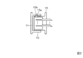
- FIGS. 1A and 1B show a configuration described in Patent Document 1 as a conventional example of this type of dust cap, and FIG. 2 shows that the dust cap shown in FIGS. 1A and 1B is a connector (round connector). It shows the assembled state.
- the dust cap 10 has a rivet guide slot 10a for guiding insertion of the rivet 15a of the connector 15 when the dust cap 10 is assembled and fixed to the connector 15, and a rivet when the connector 15 and the dust cap 10 are fixed.
- a rivet fixing surface 10b having a surface structure to which 15a can be fixed is provided, and a dust-proof material 11 such as silicon rubber, which also serves as dust-proof, is provided at the insertion end portion 10c that contacts when the tip portion of the connector 15 is inserted. Is provided.
- the dust cap 10 and the connector 15 are assembled by inserting the rivet guide slot 10a in accordance with the position of the rivet 15a, pressing the dust cap 10 against the connector 15, and the dust cap 10 at a position where the rivet 15a exceeds the rivet fixing surface 10b. This is done by rotating 10. Thereby, the dust cap 10 is fixed by the rivet 15a and the rivet fixing surface 10b by the repulsive force of the dustproof material 11.
- the dustproof material 11 such as silicon rubber provided inside the dust cap 10 is pressed against the tip of the connector 15, thereby generating a repulsive force due to the elasticity of the dustproof material 11. By this repulsive force, the dust cap 10 is locked with respect to the connector 15.
- the dustproof material 11 is always stressed.
- the silicon rubber of the dustproof material 11 deteriorates, that is, becomes hard and elastic. This causes a problem that the dust cap 10 is easily detached due to a decrease in locking force.
- An object of the present invention is to provide a dust cap that does not lose its locking force even when used for a long period of time, and is therefore difficult to come off.
- the dust cap attached to the receptacle when the plug is not fitted in the bayonet locking connector has an insertion portion on the distal end side, which is inserted into the receptacle shell while the circumferential rotation of the shell is restricted.
- a housing provided with a lid on the rear end side, and a cantilever extending in a direction crossing the insertion direction of the insertion portion provided between the insertion portion and the lid portion, and a cylindrical inner peripheral surface Having a protrusion for bayonet locking on the inner peripheral surface on the front end side, comprising a coupling which is attached to be rotatable relative to the housing around the housing and whose rear end is covered by the lid portion,
- the tip of the cantilever is positioned in a groove formed on the inner peripheral surface of the coupling, and the protrusion is inserted in a bayonet locking recess formed on the outer peripheral surface of the shell.
- Cantilever is not deflected, in order to release the locked state, when rotating the coupling relative to the housing, the cantilever bends the tip portion is pushed by the inner wall of the groove.
- the cantilever for maintaining the locked state of the dust cap with respect to the receptacle is not stressed in the locked state. Therefore, even if it is used for a long time, the cantilever beam is not deteriorated and the elasticity is not lowered, and the locking force is not lowered. Thereby, the dust cap which is hard to come off and excellent in that point can be provided.
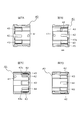
- FIG. 1A is a front view showing a conventional example of a dust cap.
- 1B is a cross-sectional view taken along the line CC of FIG. 1A.
- FIG. 2 is a cross-sectional view showing a state in which the dust cap shown in FIGS. 1A and 1B is assembled to the connector.
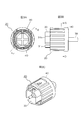
- FIG. 3A is a front view showing an embodiment of a dust cap according to the present invention.
- 3B is a right side view of the dust cap shown in FIG. 3A.
- FIG. 3C is a perspective view thereof.
- 4A is a cross-sectional view taken along the line DD of FIG. 3B.
- FIG. 4B is a cross-sectional view taken along the line EE of FIG. 3A with the right side view of FIG.
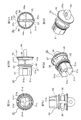
- FIG. 5A is a front view of the housing in FIG. 3C.
- FIG. 5B is a right side view of the housing shown in FIG. 5A.
- FIG. 5C is a bottom view of the housing shown in FIG. 5A.
- FIG. 5D is a cross-sectional view taken along the line GG of FIG. 5B.
- FIG. 5E is a perspective view of the housing shown in FIG. 5A.
- FIG. 5F is a perspective view of the housing shown in FIG. 5A.
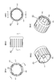
- 6A is a front view of the coupling in FIG. 3C.
- 6B is a right side view of the coupling shown in FIG. 6A.
- FIG. 6C is a rear view of the coupling shown in FIG. 6A.
- 6D is a perspective view of the coupling shown in FIG. 6A.
- FIG. 6E is a perspective view of the coupling shown in FIG. 6A.
- FIG. 7A is an enlarged sectional view taken along line FF in FIG. 6C.
- FIG. 7B is an enlarged sectional view taken along line GG in FIG. 6C.
- FIG. 7C is an enlarged sectional view taken along line HH in FIG. 6A.
- FIG. 7D is an enlarged sectional view taken along line JJ of FIG. 6B.
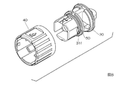
- FIG. 8 is a view for explaining assembly of the dust cap shown in FIG. 3C.
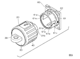
- FIG. 9 is a view for explaining attachment of the dust cap to the receptacle.
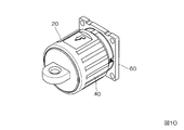
- FIG. 10 is a perspective view showing a state in which the dust cap is attached to the receptacle.
- FIG. 11 is a cross-sectional perspective view of FIG.
- FIGS. 3A to 3C show the appearance of an embodiment of the dust cap according to the present invention
- FIGS. 4A to 4C show the cross-sectional structure thereof.
- the dust cap 20 is attached to a receptacle when the plug is not fitted in a bayonet lock type connector composed of a plug and a receptacle, and includes a housing 30, a coupling 40, and an O-ring 50.
- 5A-5F show details of the housing 30, and FIGS. 6A-6E and 7A-7D show details of the coupling 40.
- the housing 30 has an insertion portion 31 to be inserted into the shell of the receptacle on the front end side as shown in FIG. 5B, and a disc-shaped lid portion 32 on the rear end side.
- the insertion portion 31 includes a cylindrical portion 31a and insertion pieces 31b and 31c formed to project forward from the cylindrical portion 31a.
- the insertion piece 31b is formed so as to protrude from a region occupying approximately 3/4 of the circumference of the cylindrical portion 31a and has a C-shaped cross section, and the insertion piece 31c is formed from the remaining 1/4 of the circumference of the cylindrical portion 31a. Protrusions are formed.
- the cylindrical surface is cut out every 90 ° on the outer peripheral surface of the insertion piece 31b having a C-shaped cross section to form three flat portions 31d.
- the three flat portions 31d are formed so as to be positioned at both ends and the center of the C-shape.
- a recess 31e is formed on the outer surface (outer peripheral surface) of the insertion piece 31c so as to extend in the protruding direction of the insertion piece 31c.
- the flat portion 31d and the recessed portion 31e are formed up to a position where they slightly enter the cylindrical portion 31a.
- a groove 31f is formed in an annular shape on the outer peripheral surface of the cylindrical portion 31a, and reinforcing ribs 31g are provided inside the cylindrical portion 31a so as to form a cross shape.
- a disc portion 33, a prismatic columnar portion 34 and a disc portion 35 are formed in this order from the insertion portion 31 side.
- the columnar portion 34 further includes a pair of cantilevers.
- a beam 36 is formed.
- the outer diameters of the disk portions 33 and 35 are larger than the outer diameter of the cylindrical portion 31 a and smaller than the outer diameter of the lid portion 32.
- the columnar portion 34 is formed on one diameter of the disk portions 33 and 35 so as to be located in a region excluding both ends of the diameter, and the pair of cantilever beams 36 are formed from opposite side surfaces of the columnar portion 34. Projecting outwardly from each other.
- the pair of cantilever beams 36 are formed so as to be positioned on a diameter orthogonal to the diameter of the disk portions 33 and 35 on which the columnar portion 34 is located.
- the columnar portion 34 and the pair of cantilever beams 36 are not illustrated. As shown in 5D, it has a cross-sectional shape.
- the pair of cantilevers 36 are thin plate-like, and the width is slightly narrowed toward the tip. In this example, the tip portion 36a of the cantilever beam 36 is slightly thicker (thickness).
- notches 37 are provided at two upper and lower positions in the diameter position where the columnar portion 34 is located, and the center of the circumferential width of the notch 37 is columnar as shown in FIG. 5D.
- the portion 34 is shifted in the clockwise direction with respect to the center line 34a.
- Cutouts 38 are also provided at two locations above and below the periphery of the disc portion 33.
- the inner bottom surface of the notches 37 and 38 is a surface in which the side surface where the cantilever 36 of the columnar portion 34 is not formed is extended.
- a knob 39 protrudes from the center of the outer surface (outer plate surface) of the lid portion 32 having a disc shape, and a hole 39a is formed through the knob 39.
- the coupling 40 has a cylindrical shape as shown in FIGS. 6A-6E and FIGS. 7A-7D, and bayonet locking protrusions 41 protrude from the inner peripheral surface of the distal end side at 180 °. Yes.
- Grooves 42 are respectively formed at positions where the projections 41 are located on the extensions where the circumferential surfaces of the coupling 40 form 180 °.
- the groove 42 is formed to extend from the rear end of the coupling 40 to substantially the center in the central axis direction of the coupling 40.
- retaining pieces 43 and two protrusions 44 are formed on the inner peripheral surface of the rear end side half of the coupling 40.
- the protrusion 44 is formed at a position shifted by 90 ° from the groove 42 in the circumferential direction of the coupling 40, and the retaining piece 43 is positioned at a position shifted by 45 ° in the circumferential direction of the groove 42 and the protrusion 44 and the coupling 40. Is formed.
- the retaining piece 43 has a rear end side of the coupling 40 as a support end and extends toward the front (the front end of the coupling 40), and the free end portion 43a is the inner end of the coupling 40. It has a shape that is raised away from the peripheral surface.
- the protrusion 44 has an elongated key shape.
- the rear ends of the retaining pieces 43 and the projections 44 are positioned slightly inside the rear ends of the couplings 40, and the inner diameter of the coupling 40 behind the rear ends of the retaining pieces 43 and the projections 44 is the front.
- a step 45 is formed to be slightly larger than the inner diameter on the side.
- the housing 30 and the coupling 40 having the above shapes are both made of resin in this example.
- An O-ring 50 is mounted in the groove 31f of the housing 30, and the housing 30 is inserted into the coupling 40 from the rear end side of the coupling 40 as shown in FIG.
- the dust cap 20 shown in 4A-4C is completed.
- the disc portion 33 of the housing 30 pushes the free end portions 43 a of the four retaining pieces 43 of the coupling 40 outward, passes through the free end portions 43 a, and spreads.
- the free end portion 43a thus elastically returns.
- the retaining piece 43 is caught on the peripheral edge of the disc portion 33.
- the lid portion 32 of the housing 30 is accommodated in the rear end portion of the coupling 40 as shown in FIG. 4B, and by pushing against the step portion 45, further pushing is prevented.
- the rear end of the coupling 40 is covered with a lid portion 32.
- the coupling 40 is prevented from slipping forward with respect to the housing 30 when the free end 43 a of the retaining piece 43 abuts against the disk portion 33 of the housing 30, while the step 45 is abutted against the lid portion 32. 30 is attached around the housing 30 so as to be prevented from coming out backward.
- the tip portions 36a of the pair of cantilevers 36 formed on the housing 30 are respectively positioned in the grooves 42 of the coupling 40 as shown in FIGS. 4A and 4C, and two protrusions formed on the coupling 40 are formed.
- the portions 44 are respectively positioned in the notches 37 of the housing 30 as shown in FIG. 4A.
- the coupling 40 is rotatable with respect to the housing 30 by the amount that the protrusion 44 can move in the circumferential direction in the notch 37. Note that the distal end sides of the insertion pieces 31 b and 31 c of the housing 30 protrude from the distal end side of the coupling 40, and the knob 39 protrudes from the rear end side of the coupling 40.
- FIG. 9 shows a state before the dust cap 20 is attached to the receptacle
- FIG. 10 shows a state after the attachment
- FIG. 11 shows a cross-sectional structure in a state where the dust cap 20 is attached to the receptacle.
- FIG. 9-11 only the shell constituting the receptacle is shown as the receptacle, and the other components are not shown.
- the shell 60 of the receptacle includes a cylindrical part 61 and a flange part 62 provided at one end of the cylindrical part 61.
- a pair of guide grooves 61 a for bayonet locking are formed on the outer peripheral surface of the cylindrical portion 61.
- One side wall on the inlet side of the guide groove 61a is a slope 61b as shown in FIG. 9, and a recess 61c is formed in the back of the slope 61b.
- the slope 61b and the recess 61c of the pair of guide grooves 61a are provided so as to overlap when the cylindrical portion 61 is rotated by 180 °.
- protrusions 61d are formed to extend in the direction of the central axis of the cylindrical portion 61, and three flat portions 61e are formed to protrude every 90 °. In FIG. 9, only one plane portion 61e is hidden and can be seen.
- the flat surface portion 31 d provided on the outer peripheral surface of the insertion piece 31 b of the housing 30 of the dust cap 20 matches the flat surface portion 61 e of the cylindrical portion 61.
- the dust cap 20 is attached to the receptacle by, for example, pinching the knob 39 of the housing 30 to insert the insertion pieces 31b and 31c into the cylindrical portion 61 of the shell 60 and pushing the dust cap 20 in.
- the protrusion 61d of the shell 60 extended in the insertion direction of the insertion pieces 31b and 31c is fitted into the recess 31e of the insertion piece 31c, and the insertion piece is formed with three plane portions 31d.
- the insertion pieces 31b and 31c are positioned when the outer peripheral shape of 31b matches the inner peripheral shape of the cylindrical portion 61 having the three flat portions 61e, that is, the housing 30 is restricted from rotating in the circumferential direction of the cylindrical portion 61 of the shell 60. Is done.
- the pair of protrusions 41 of the coupling 40 abut against the inclined surface 61b of the guide groove 61a of the shell 60, and are guided by the inclined surface 61b, so that only the coupling 40 starts to rotate.
- the pair of cantilevers 36 of the housing 30 is not bent as shown in FIG. 4A, that is, the tip 36 a of the cantilever 36 located in the groove 42 of the coupling 40 is the inner wall of the groove 42. 42a, the tip part 36a of the cantilever 36 is pushed by the inner wall 42a of the groove 42 when the coupling 40 starts to rotate. Therefore, as the coupling 40 rotates, the pair of cantilevers 36 I will bend.
- the protrusion 41 of the coupling 40 gets over the slope 61b.
- the pair of cantilever beams 36 that have been bent returns to their initial state due to elasticity.
- the inner wall 42a of the groove 42 is pushed by the tip 36a of the cantilever beam 36 to rotate in the reverse direction, and the protrusion 41 is fitted into the recess 61c at the back of the slope 61b. It becomes locked.
- the dust cap 20 is attached to the shell 60 of the receptacle, and is locked and covers the opening of the shell 60.
- the locked state the pair of cantilever beams 36 of the dust cap 20 are not bent, but the locked state is maintained by the presence of the cantilever beams 36 in the initial state.
- the pair of cantilevers 36 is When the tip 36a is pushed by the inner wall 42a of the groove 42 of the coupling 40 and is attached, the cantilever 36 returns to the initial state without deflection when the dust cap 20 is detached from the receptacle.
- the two protrusions 44 formed on the coupling 40 in any direction are constituted by both side walls of the notches 37 formed on the disk portion 35 of the housing 30.
- the abutting surfaces 37a and 37b By striking against the abutting surfaces 37a and 37b, excessive rotation of the coupling 40 is prevented, thereby preventing the occurrence of problems such that the cantilever 36 is excessively bent and broken. ing.
- the cantilever beam 36 is not stressed in the locked state with respect to the receptacle, and thus the locking force does not decrease even when used for a long time. It is possible to obtain a dust cap that does not easily come off at a point.
- the cylindrical portion 61 of the shell 60 enters between the coupling 40 of the dust cap 20 and the insertion portion 31 of the housing 30 as shown in FIG. Since the O-ring 50 is sandwiched between the inner peripheral surface 61 and the housing 30, by providing such an O-ring 50, an excellent dustproof structure is realized in this example.
- the housing 30 of the dust cap 20 is provided with the insertion pieces 31b and 31c that sufficiently enter the cylindrical portion 61 of the shell 60 as shown in FIG.
- the attachment strength of the dust cap 20 can be improved.
- the dust cap 20 receives external force from the lateral direction. Can be made difficult to come off and hard to break.
- the outer shape of the coupling 40 is also cylindrical, but the outer shape of the coupling 40 may be any shape as long as it has an inner peripheral surface that matches the cylindrical portion 61 of the shell 60.
- the tip portion 36a of the cantilever beam 36 is slightly thicker in this example, but may be a cantilever beam 36 having a uniform thickness without increasing the wall thickness.
- tip part 36a is enlarged, formation of the groove
- the housing 30 is made of resin in the above-described example, but is not limited to resin, and may be made of metal.
- the cantilever 36 may be made of metal, and the cantilever 36 may be attached by insert molding or press-fitting to form the housing 30 with resin.
- the number of cantilever beams 36 may be three or more, or may be one.
- it is preferable that their tip portions are positioned at rotationally symmetric positions around the central axis of the coupling 40.
- the cantilever beam 36 is supported by the columnar portion 34, that is, the support end of the cantilever beam 36 is located at the center portion of the housing 30, and the cantilever beam 36 is outward from the center portion of the housing 30.
- the support portion (columnar portion 34 in the above example) that supports the cantilever beam 36 is displaced from the center portion of the housing 30, and the support end of the cantilever beam 36 is displaced from the center portion of the housing 30. It may be in a different position. If the supporting end of the cantilever beam 36 is in such a position, the length of the cantilever beam 36 can be increased.
- the cantilever beam 36 is extended in a direction orthogonal to the insertion direction of the insertion portion 31 with respect to the shell 60, but does not necessarily extend in a direction orthogonal to the insertion direction, and intersects the insertion direction. It only needs to be extended in the direction.
Landscapes
- Connector Housings Or Holding Contact Members (AREA)
Abstract
Description
Claims (6)
- バヨネットロック式コネクタにおけるプラグ非嵌合時のレセプタクルに取り付けられるダストキャップであり、
前記レセプタクルのシェルに、前記シェルの周方向の回転が規制されて挿入される挿入部を先端側に有し、蓋部を後端側に備え、前記挿入部の挿入方向と交差する方向に伸長された片持梁が前記挿入部と前記蓋部との間に設けられたハウジングと、
円筒状の内周面を有し、先端側内周面にバヨネットロック用の突起を備え、前記ハウジングの回りに前記ハウジングに対して回転可能とされて取り付けられて後端が前記蓋部によって蓋されたカップリングとよりなり、
前記片持梁の先端部は前記カップリングの内周面に形成された溝内に位置し、
前記突起が前記シェルの外周面に形成されているバヨネットロック用の凹みに嵌まり込んだロック状態では前記片持梁はたわまず、
前記ロック状態を解除すべく、前記ハウジングに対して前記カップリングを回転すると、前記片持梁は前記先端部が前記溝の内壁によって押されてたわむ。 - 請求項1のダストキャップにおいて、
前記片持梁を複数備え、
複数の前記片持梁の前記先端部は前記カップリングの中心軸を中心とする回転対称位置に位置されている。 - 請求項1又は2のダストキャップにおいて、
前記挿入方向に延伸されて前記シェルの内周面に形成されている突条が嵌まり込む凹部が前記挿入部の外面に形成されている。 - 請求項1乃至3のいずれかのダストキャップにおいて、
前記カップリングの内周面に突部が突出形成され、
前記突部が突き当たることによって前記カップリングの過大な回転を阻止する突き当て面が前記ハウジングに形成されている。 - 請求項1乃至4のいずれかのダストキャップにおいて、
前記シェルの内周面と前記ハウジングとによって挟み込まれるOリングが前記ハウジングの外周面に装着されている。 - 請求項1乃至5のいずれかのダストキャップにおいて、
前記蓋部の外面につまみが突出形成されている。
Priority Applications (2)
| Application Number | Priority Date | Filing Date | Title |
|---|---|---|---|
| KR1020177024297A KR101930064B1 (ko) | 2015-04-27 | 2016-01-20 | 더스트 캡 |
| US15/559,491 US10003154B2 (en) | 2015-04-27 | 2016-01-20 | Dust cap having a housing with a cantilever beam secured to a shell of a receptacle by a coupling member |
Applications Claiming Priority (2)
| Application Number | Priority Date | Filing Date | Title |
|---|---|---|---|
| JP2015-090589 | 2015-04-27 | ||
| JP2015090589A JP5925938B1 (ja) | 2015-04-27 | 2015-04-27 | ダストキャップ |
Publications (1)
| Publication Number | Publication Date |
|---|---|
| WO2016174883A1 true WO2016174883A1 (ja) | 2016-11-03 |
Family
ID=56069537
Family Applications (1)
| Application Number | Title | Priority Date | Filing Date |
|---|---|---|---|
| PCT/JP2016/051534 Ceased WO2016174883A1 (ja) | 2015-04-27 | 2016-01-20 | ダストキャップ |
Country Status (4)
| Country | Link |
|---|---|
| US (1) | US10003154B2 (ja) |
| JP (1) | JP5925938B1 (ja) |
| KR (1) | KR101930064B1 (ja) |
| WO (1) | WO2016174883A1 (ja) |
Families Citing this family (7)
| Publication number | Priority date | Publication date | Assignee | Title |
|---|---|---|---|---|
| JP1595923S (ja) * | 2017-05-17 | 2018-01-29 | ||
| DE102019002346B4 (de) * | 2019-03-29 | 2025-11-27 | Yamaichi Electronics Deutschland Gmbh | Verwendung einer universellen Verschlusskappe, Verschlusssystem für Steckverbinder, Verfahren zum Verschließen eines Steckverbinders |
| DE102019002345A1 (de) * | 2019-03-29 | 2020-10-01 | Yamaichi Electronics Deutschland Gmbh | Verschlusskappe zum Verschließen einer Steckverbinder-Buchse, System bestehend aus einer Steckverbinder-Buchse und einer universellen Verschlusskappe, und Verfahren zum Verschließen einer Steckverbinder-Buchse |
| JP7314012B2 (ja) | 2019-10-07 | 2023-07-25 | 日本航空電子工業株式会社 | ソケットコンタクト及びコネクタ |
| JP2022120628A (ja) * | 2021-02-05 | 2022-08-18 | 住友電装株式会社 | 車両用コネクタ |
| JP7748856B2 (ja) * | 2021-11-12 | 2025-10-03 | 日本航空電子工業株式会社 | コネクタ組立体および防水キャップ |
| JP2026005655A (ja) * | 2024-06-27 | 2026-01-16 | 矢崎総業株式会社 | キャップ、及び、キャップ付きユニット |
Citations (4)
| Publication number | Priority date | Publication date | Assignee | Title |
|---|---|---|---|---|
| JPH01104670U (ja) * | 1987-12-29 | 1989-07-14 | ||
| JPH11126649A (ja) * | 1997-10-21 | 1999-05-11 | Yazaki Corp | キャップ部材のロック構造 |
| US20070012474A1 (en) * | 2005-06-30 | 2007-01-18 | Leviton Manufacturing Co., Inc. | Communication wall receptacle cap retaining system and method |
| JP2012226864A (ja) * | 2011-04-15 | 2012-11-15 | Nec Corp | 防水ユニットに対する樹脂製部材の取り付け構造、防水ユニット、及び樹脂製部材の取り付け方法 |
Family Cites Families (3)
| Publication number | Priority date | Publication date | Assignee | Title |
|---|---|---|---|---|
| EP1880448B1 (de) * | 2006-05-11 | 2013-10-23 | ABL SURSUM BAYERISCHE ELEKTROZUBEHÖR GmbH & Co. KG | Drehbare einspeisung |
| US20090163058A1 (en) * | 2007-12-21 | 2009-06-25 | Darrell Wayne Craig | Electrical connector with tethered cover |
| DE102013107282A1 (de) * | 2013-07-10 | 2015-01-15 | Harting Electric Gmbh & Co. Kg | Verschlusskappe für einen Steckverbinder |
-
2015
- 2015-04-27 JP JP2015090589A patent/JP5925938B1/ja active Active
-
2016
- 2016-01-20 US US15/559,491 patent/US10003154B2/en active Active
- 2016-01-20 KR KR1020177024297A patent/KR101930064B1/ko active Active
- 2016-01-20 WO PCT/JP2016/051534 patent/WO2016174883A1/ja not_active Ceased
Patent Citations (4)
| Publication number | Priority date | Publication date | Assignee | Title |
|---|---|---|---|---|
| JPH01104670U (ja) * | 1987-12-29 | 1989-07-14 | ||
| JPH11126649A (ja) * | 1997-10-21 | 1999-05-11 | Yazaki Corp | キャップ部材のロック構造 |
| US20070012474A1 (en) * | 2005-06-30 | 2007-01-18 | Leviton Manufacturing Co., Inc. | Communication wall receptacle cap retaining system and method |
| JP2012226864A (ja) * | 2011-04-15 | 2012-11-15 | Nec Corp | 防水ユニットに対する樹脂製部材の取り付け構造、防水ユニット、及び樹脂製部材の取り付け方法 |
Also Published As
| Publication number | Publication date |
|---|---|
| US10003154B2 (en) | 2018-06-19 |
| KR20170108145A (ko) | 2017-09-26 |
| US20180123280A1 (en) | 2018-05-03 |
| JP5925938B1 (ja) | 2016-05-25 |
| KR101930064B1 (ko) | 2018-12-17 |
| JP2016207572A (ja) | 2016-12-08 |
Similar Documents
| Publication | Publication Date | Title |
|---|---|---|
| JP5925938B1 (ja) | ダストキャップ | |
| CN101981329B (zh) | 夹子 | |
| CA2613658C (en) | Optical connector excellent in maintenance of a connected state | |
| JP5627940B2 (ja) | グロメット | |
| JPH07287143A (ja) | プラグ誤脱防止機構 | |
| JP5703139B2 (ja) | コネクタ | |
| JPH1027646A (ja) | コネクタ | |
| JP2013047804A (ja) | 光ファイバコネクタ | |
| KR20180077078A (ko) | 전기 커넥터 및 전기 커넥터 쌍 | |
| JP2015183851A (ja) | 差込継手部材 | |
| JP2019021497A (ja) | レバー式コネクタ | |
| JP5811078B2 (ja) | レバー式コネクタ | |
| JP2020126714A (ja) | レバー式コネクタ | |
| WO2019124030A1 (ja) | コネクタ | |
| JP2007234563A (ja) | レバー式コネクタ | |
| JP6571910B2 (ja) | レバー式コネクタ | |
| JP5922487B2 (ja) | 部材の固定装置 | |
| JP6861582B2 (ja) | コネクタ | |
| JP7123708B2 (ja) | 光コネクタ | |
| JP7528877B2 (ja) | コネクタ | |
| JP6839608B2 (ja) | コネクタ | |
| JP6574686B2 (ja) | コルゲートチューブ保持具、及び、保持具付きコルゲートチューブ | |
| JP6707229B2 (ja) | コネクタ | |
| JP6211794B2 (ja) | 光コネクタ | |
| JP6272266B2 (ja) | プラガブル光送受信モジュール |
Legal Events
| Date | Code | Title | Description |
|---|---|---|---|
| 121 | Ep: the epo has been informed by wipo that ep was designated in this application |
Ref document number: 16786160 Country of ref document: EP Kind code of ref document: A1 |
|
| ENP | Entry into the national phase |
Ref document number: 20177024297 Country of ref document: KR Kind code of ref document: A |
|
| WWE | Wipo information: entry into national phase |
Ref document number: 15559491 Country of ref document: US |
|
| NENP | Non-entry into the national phase |
Ref country code: DE |
|
| 122 | Ep: pct application non-entry in european phase |
Ref document number: 16786160 Country of ref document: EP Kind code of ref document: A1 |