WO2016174846A1 - 液体ブロー成形装置および液体ブロー成形方法 - Google Patents
液体ブロー成形装置および液体ブロー成形方法 Download PDFInfo
- Publication number
- WO2016174846A1 WO2016174846A1 PCT/JP2016/002074 JP2016002074W WO2016174846A1 WO 2016174846 A1 WO2016174846 A1 WO 2016174846A1 JP 2016002074 W JP2016002074 W JP 2016002074W WO 2016174846 A1 WO2016174846 A1 WO 2016174846A1
- Authority
- WO
- WIPO (PCT)
- Prior art keywords
- liquid
- preform
- pressurized liquid
- blow molding
- supply path
- Prior art date
Links
Images

Classifications
-
- B—PERFORMING OPERATIONS; TRANSPORTING
- B29—WORKING OF PLASTICS; WORKING OF SUBSTANCES IN A PLASTIC STATE IN GENERAL
- B29C—SHAPING OR JOINING OF PLASTICS; SHAPING OF MATERIAL IN A PLASTIC STATE, NOT OTHERWISE PROVIDED FOR; AFTER-TREATMENT OF THE SHAPED PRODUCTS, e.g. REPAIRING
- B29C49/00—Blow-moulding, i.e. blowing a preform or parison to a desired shape within a mould; Apparatus therefor
- B29C49/42—Component parts, details or accessories; Auxiliary operations
- B29C49/46—Component parts, details or accessories; Auxiliary operations characterised by using particular environment or blow fluids other than air
-
- B—PERFORMING OPERATIONS; TRANSPORTING
- B29—WORKING OF PLASTICS; WORKING OF SUBSTANCES IN A PLASTIC STATE IN GENERAL
- B29C—SHAPING OR JOINING OF PLASTICS; SHAPING OF MATERIAL IN A PLASTIC STATE, NOT OTHERWISE PROVIDED FOR; AFTER-TREATMENT OF THE SHAPED PRODUCTS, e.g. REPAIRING
- B29C49/00—Blow-moulding, i.e. blowing a preform or parison to a desired shape within a mould; Apparatus therefor
- B29C49/42—Component parts, details or accessories; Auxiliary operations
- B29C49/4205—Handling means, e.g. transfer, loading or discharging means
- B29C49/42069—Means explicitly adapted for transporting blown article
-
- B—PERFORMING OPERATIONS; TRANSPORTING
- B29—WORKING OF PLASTICS; WORKING OF SUBSTANCES IN A PLASTIC STATE IN GENERAL
- B29C—SHAPING OR JOINING OF PLASTICS; SHAPING OF MATERIAL IN A PLASTIC STATE, NOT OTHERWISE PROVIDED FOR; AFTER-TREATMENT OF THE SHAPED PRODUCTS, e.g. REPAIRING
- B29C49/00—Blow-moulding, i.e. blowing a preform or parison to a desired shape within a mould; Apparatus therefor
- B29C49/42—Component parts, details or accessories; Auxiliary operations
- B29C49/78—Measuring, controlling or regulating
- B29C49/783—Measuring, controlling or regulating blowing pressure
-
- B—PERFORMING OPERATIONS; TRANSPORTING
- B29—WORKING OF PLASTICS; WORKING OF SUBSTANCES IN A PLASTIC STATE IN GENERAL
- B29C—SHAPING OR JOINING OF PLASTICS; SHAPING OF MATERIAL IN A PLASTIC STATE, NOT OTHERWISE PROVIDED FOR; AFTER-TREATMENT OF THE SHAPED PRODUCTS, e.g. REPAIRING
- B29C49/00—Blow-moulding, i.e. blowing a preform or parison to a desired shape within a mould; Apparatus therefor
- B29C49/42—Component parts, details or accessories; Auxiliary operations
- B29C49/46—Component parts, details or accessories; Auxiliary operations characterised by using particular environment or blow fluids other than air
- B29C2049/4602—Blowing fluids
- B29C2049/465—Blowing fluids being incompressible
- B29C2049/4664—Blowing fluids being incompressible staying in the final article
-
- B—PERFORMING OPERATIONS; TRANSPORTING
- B29—WORKING OF PLASTICS; WORKING OF SUBSTANCES IN A PLASTIC STATE IN GENERAL
- B29C—SHAPING OR JOINING OF PLASTICS; SHAPING OF MATERIAL IN A PLASTIC STATE, NOT OTHERWISE PROVIDED FOR; AFTER-TREATMENT OF THE SHAPED PRODUCTS, e.g. REPAIRING
- B29C49/00—Blow-moulding, i.e. blowing a preform or parison to a desired shape within a mould; Apparatus therefor
- B29C49/42—Component parts, details or accessories; Auxiliary operations
- B29C49/78—Measuring, controlling or regulating
- B29C49/783—Measuring, controlling or regulating blowing pressure
- B29C2049/7834—Pressure increase speed, e.g. dependent on stretch or position
-
- B—PERFORMING OPERATIONS; TRANSPORTING
- B29—WORKING OF PLASTICS; WORKING OF SUBSTANCES IN A PLASTIC STATE IN GENERAL
- B29C—SHAPING OR JOINING OF PLASTICS; SHAPING OF MATERIAL IN A PLASTIC STATE, NOT OTHERWISE PROVIDED FOR; AFTER-TREATMENT OF THE SHAPED PRODUCTS, e.g. REPAIRING
- B29C2949/00—Indexing scheme relating to blow-moulding
- B29C2949/07—Preforms or parisons characterised by their configuration
- B29C2949/0715—Preforms or parisons characterised by their configuration the preform having one end closed
-
- B—PERFORMING OPERATIONS; TRANSPORTING
- B29—WORKING OF PLASTICS; WORKING OF SUBSTANCES IN A PLASTIC STATE IN GENERAL
- B29C—SHAPING OR JOINING OF PLASTICS; SHAPING OF MATERIAL IN A PLASTIC STATE, NOT OTHERWISE PROVIDED FOR; AFTER-TREATMENT OF THE SHAPED PRODUCTS, e.g. REPAIRING
- B29C49/00—Blow-moulding, i.e. blowing a preform or parison to a desired shape within a mould; Apparatus therefor
- B29C49/02—Combined blow-moulding and manufacture of the preform or the parison
- B29C49/06—Injection blow-moulding
-
- B—PERFORMING OPERATIONS; TRANSPORTING
- B29—WORKING OF PLASTICS; WORKING OF SUBSTANCES IN A PLASTIC STATE IN GENERAL
- B29C—SHAPING OR JOINING OF PLASTICS; SHAPING OF MATERIAL IN A PLASTIC STATE, NOT OTHERWISE PROVIDED FOR; AFTER-TREATMENT OF THE SHAPED PRODUCTS, e.g. REPAIRING
- B29C49/00—Blow-moulding, i.e. blowing a preform or parison to a desired shape within a mould; Apparatus therefor
- B29C49/08—Biaxial stretching during blow-moulding
- B29C49/10—Biaxial stretching during blow-moulding using mechanical means for prestretching
- B29C49/12—Stretching rods
-
- B—PERFORMING OPERATIONS; TRANSPORTING
- B29—WORKING OF PLASTICS; WORKING OF SUBSTANCES IN A PLASTIC STATE IN GENERAL
- B29C—SHAPING OR JOINING OF PLASTICS; SHAPING OF MATERIAL IN A PLASTIC STATE, NOT OTHERWISE PROVIDED FOR; AFTER-TREATMENT OF THE SHAPED PRODUCTS, e.g. REPAIRING
- B29C49/00—Blow-moulding, i.e. blowing a preform or parison to a desired shape within a mould; Apparatus therefor
- B29C49/42—Component parts, details or accessories; Auxiliary operations
- B29C49/58—Blowing means
-
- B—PERFORMING OPERATIONS; TRANSPORTING
- B29—WORKING OF PLASTICS; WORKING OF SUBSTANCES IN A PLASTIC STATE IN GENERAL
- B29L—INDEXING SCHEME ASSOCIATED WITH SUBCLASS B29C, RELATING TO PARTICULAR ARTICLES
- B29L2031/00—Other particular articles
- B29L2031/712—Containers; Packaging elements or accessories, Packages
- B29L2031/7158—Bottles
Definitions
- the present invention relates to a liquid blow molding apparatus and a liquid blow molding method for supplying a pressurized liquid to a resin preform and performing liquid blow molding on a container having a predetermined shape.
- Resin containers such as polypropylene (PP) bottles and polyethylene terephthalate (PET) bottles are used to contain various liquids such as beverages, cosmetics, chemicals, detergents, and shampoos. Yes.
- PP polypropylene
- PET polyethylene terephthalate
- Such a container is generally manufactured by blow-molding a preform formed into a bottomed cylindrical shape from a resin material.
- a blow molding apparatus for blow molding a preform a liquid blow molding apparatus using a liquid as a pressurized fluid supplied to the preform is known.
- a blow mold in which a preform is disposed, a blow nozzle that engages with a mouth portion of the preform disposed in the blow mold, and a supply path connected to the blow nozzle are pressurized.
- a pressurized liquid supply unit that supplies liquid and a seal member that opens and closes the supply path with respect to the blow nozzle, and supplies the pressurized liquid from the pressurized liquid supply unit to the supply path and opens the seal member
- the liquid blow molding apparatus is described in which the liquid pressurized in step 1 is supplied into the preform and the preform is liquid blow molded into a container having a predetermined shape. According to such a liquid blow molding apparatus, by using the content liquid finally contained in the container as a product such as a beverage as the liquid to be supplied to the preform, the process of filling the content liquid into the container after molding Can be omitted, and the production process and the configuration of the liquid blow molding apparatus can be simplified.
- liquid blow molding apparatus there is an apparatus that performs liquid blow molding by starting the opening operation of the seal member at the same time as the supply of the pressurized liquid from the pressurized liquid supply unit to the supply path is started.
- the present invention has been made in view of such a problem, and an object of the present invention is to provide a liquid blower that stabilizes the behavior of the liquid at the initial stage of supplying the liquid into the preform and improves the moldability of the preform.
- the object is to provide a molding apparatus and a liquid blow molding method.
- the liquid blow molding apparatus of the present invention is a liquid blow molding apparatus for liquid blow molding a resin preform into a container having a predetermined shape, and a blow molding die in which the preform is disposed, and a mouth portion of the preform A blow nozzle that engages with the nozzle, a pressurized liquid supply unit that supplies pressurized liquid to a supply path connected to the blow nozzle, and a supply path that opens and closes the supply path with respect to the blow nozzle.
- the pressurized liquid supply unit starts supplying pressurized liquid to the supply path after opening of the seal member is started.
- the liquid blow molding apparatus of the present invention in the above-described configuration, is the time from when the opening of the seal member is started until the pressurized liquid supply unit starts supplying pressurized liquid to the supply path, It is preferable that it is 0.01 second or more and 0.05 second or less.
- the liquid blow molding apparatus of the present invention in the above-described configuration, is the time from when the opening of the seal member is started until the pressurized liquid supply unit starts supplying pressurized liquid to the supply path, It is preferable to set it to 0.01 seconds or more and 0.03 seconds or less.
- the liquid blow molding apparatus of the present invention preferably includes a stretching rod for stretching the preform in the longitudinal direction.
- the liquid blow molding method of the present invention is a liquid blow molding method in which a resin preform is liquid blow molded into a container having a predetermined shape, and a blow mold in which the preform is disposed, and a mouth portion of the preform A blow nozzle that engages with the nozzle, a pressurized liquid supply unit that supplies pressurized liquid to a supply path connected to the blow nozzle, and a supply path that opens and closes the supply path with respect to the blow nozzle. And a pressurizing liquid supply unit starts supplying pressurized liquid to the supply path after the opening of the sealing member is started. .
- the time from when the opening of the seal member is started to when the pressurized liquid supply unit starts supplying pressurized liquid to the supply path It is preferable that it is 0.01 second or more and 0.05 second or less.
- the time from when the opening of the seal member is started to when the pressurized liquid supply unit starts supplying pressurized liquid to the supply path It is preferable to set it to 0.01 seconds or more and 0.03 seconds or less.
- the pressurized liquid supply unit starts supplying the pressurized liquid to the supply channel, so that the liquid in the supply channel is discharged before the seal member is opened. Since it is possible to prevent the pressurized liquid supply unit from being pressurized beyond a predetermined value, the behavior of the liquid at the initial stage of supplying the liquid into the preform is stabilized and the moldability of the preform is improved. be able to.
- a liquid blow molding apparatus and a liquid blow molding method that stabilize the behavior of the liquid at the initial stage of supplying the liquid into the preform and improve the moldability of the preform. Can do.
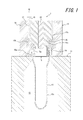
- a liquid blow molding apparatus 1 performs a liquid blow molding of a resin preform 10 into a container having a predetermined shape by a liquid blow molding method according to an embodiment of the present invention.
- the container is manufactured.
- the liquid blow molding is a blow molding using a pressurized liquid instead of the pressurized air as the pressurized fluid supplied to the preform 10.
- the liquid blow molding apparatus 1 has a blow molding die 11 composed of, for example, a blow molding die. Although only a part is shown in FIG. 1, the cavity 12 of the blow mold 11 has a bottle shape and opens upward on the upper surface of the blow mold 11. Although details are not shown, the blow mold 11 can be opened left and right, and the molded product can be taken out from the blow mold 11 by opening the blow mold 11.
- the preform 10 is placed in a blow mold 11 and is liquid blow molded by the liquid blow molding apparatus 1 to form a container.
- a resin material that exhibits stretchability by heating such as polypropylene (PP) or polyethylene terephthalate (PET) is formed by means of injection molding, compression molding, extrusion molding, or the like. Can be used that is formed into a bottomed cylindrical shape (substantially test tube).
- PP polypropylene
- PET polyethylene terephthalate
- Such a preform 10 is preheated to a predetermined temperature that exhibits stretchability, and is placed in the blow mold 11 in an upright posture in which the mouth portion 10a protrudes upward from the cavity 12.
- the preform 10 is not limited to a single layer structure formed of only one type of resin material, but may have a stacked structure in which a plurality of types of resin materials are stacked. In this case, a plurality of resin layers can be bonded to each other, but in addition to this, a laminated structure in which the outer layer and the inner layer are formed of different materials and stacked so as not to adhere to each other
- the laminated structure may have a laminated structure in which an adhesive layer is provided in an axial band between the outer layer and the inner layer.
- the said preform 10 can be formed in the lamination peeling container of a predetermined shape with the liquid blow molding apparatus 1.
- the preform 10 having a laminated structure is not limited to the above, and any layer structure may be used.
- a nozzle unit 13 is provided on the upper side of the blow mold 11 so as to be movable relative to the blow mold 11 in the vertical direction.
- the nozzle unit 13 has a main body block 14 and a blow nozzle 15.
- the blow nozzle 15 includes a nozzle body 15a formed in a cylindrical shape having a smaller diameter than the inner diameter of the mouth portion 10a of the preform 10 and a large-diameter clamping portion 15b formed integrally with the nozzle body 15a.
- the structure is integrally formed of a resin material or the like, and the clamping portion 15 b is fixed to the main body block 14 by being fitted into the inner surface of the main body block 14.
- the nozzle body 15a is disposed coaxially with the cavity 12 of the blow mold 11 so that when the nozzle unit 13 is lowered to a predetermined position, the nozzle body 15a engages with the mouth portion 10a of the preform 10 attached to the blow mold 11. It has become.
- Reference numeral 16 denotes a seal body that seals between the nozzle body 15a and the mouth portion 10a.
- a supply path 17 which is coaxial with the nozzle main body 15a and extends in the vertical direction, and this supply path 17 is connected to the blow nozzle 15 at the lower end thereof.
- a pressurized liquid supply unit 19 is connected to the supply path 17 via a pipe 18.
- the pressurized liquid supply unit 19 can supply liquid pressurized to a predetermined pressure to the supply path 17 via the pipe 18.
- the pressurized liquid is supplied from the pressurized liquid supply unit 19 to the supply path 17, the liquid is supplied from the supply path 17 to the inside of the preform 10 disposed in the blow mold 11 through the blow nozzle 15.
- the preform 10 is liquid blow molded into a container having a shape along the cavity 12 of the blow mold 11.
- the pressurized liquid supply unit 19 for example, a configuration using a plunger pump as a pressurizing source is preferably used, but a liquid pressurized to a predetermined pressure can be supplied into the preform 10. Any other configuration can be used.
- a seal member 20 is arranged to open and close the supply path 17 with respect to the blow nozzle 15, that is, to open and close the flow path between the supply path 17 and the blow nozzle 15. .
- the seal member 20 is formed in a columnar shape extending along the axis of the supply path 17 and is relatively movable in the vertical direction with respect to the main body block 14 inside the supply path 17.
- a tapered closing surface 15c is provided on the upper surface of the sandwiching portion 15b of the blow nozzle 15.
- the supply path 17 is closed with respect to the blow nozzle 15.
- the sealing member 20 moves upward and the tapered surface 20a provided at the lower end of the sealing member 20 is separated from the closing surface 15c, the supply path 17 and the nozzle body 15a are communicated, and the supply path 17 is connected to the blow nozzle 15. Are opened, that is, opened.
- the pressurized liquid supply unit 19 is engaged with the nozzle body 15 a engaged with the mouth portion 10 a of the preform 10, the seal member 20 is opened, and the supply path 17 is communicated with the blow nozzle 15. ,
- the pressurized liquid is supplied into the preform 10 from the pressurized liquid supply section 19 via the supply path 17 and the blow nozzle 15, and the preform 10 can be subjected to liquid blow molding.
- the liquid blow molding apparatus 1 may be configured such that the extending rod 22 is slidably mounted in the insertion hole formed in the central portion of the seal member 20.
- the extending rod 22 is movable relative to the seal member 20 in the vertical direction (axial direction), and is directed downward (bottom of the cavity 12) with respect to the seal member 20 as shown in FIG.
- the bottom portion of the main body portion 10b of the preform 10 disposed in the blow mold 11 is pushed downward to extend the main body portion 10b in the axial direction (longitudinal direction) inside the cavity 12.
- the liquid blow molding apparatus 1 uses a liquid that is pressurized while stretching the preform 10 disposed in the blow molding die 11 in the longitudinal direction using the stretching rod 22. It is configured to perform biaxial stretch blow molding that extends in the radial direction.
- the liquid blow molding apparatus 1 opens the seal member 20 and allows the supply path 17 to communicate with the blow nozzle 15, thereby adding pressure.
- the pressurized liquid is supplied to the preform 10 through the blow nozzle 15, and liquid blow molding is performed.
- the opening of the seal member 20 is started (the opening operation of the seal member 20 is started)
- supply of the pressurized liquid to the supply path 17 by the pressurized liquid supply unit 19 is started. Yes.
- the supply of the pressurized liquid to the supply passage 17 by the pressurized liquid supply unit 19 is not started at the same time when the opening of the seal member 20 is started, but the seal After the opening of the member 20 is started, supply of the pressurized liquid to the supply path 17 by the pressurized liquid supply unit 19 is started.
- the pressurized liquid supply part 19 prevents the liquid in the supply path 17 from being pressurized beyond a predetermined value, and the seal member 20 can sufficiently flow the liquid.
- the liquid is supplied to the preform 10 at a desired pressure when the opening is opened to stabilize the behavior of the liquid at the initial stage of supplying the liquid into the preform 10.
- the formability of the reform 10 can be improved.
- the seal member 20 is preferably configured to start opening at the same time as the opening operation thereof is started. However, the seal member 20 is configured to start opening after a predetermined time has elapsed since the opening operation started. It may be a thing. In this case, the pressurized liquid supply unit 19 is not based on the time when the seal member 20 starts to open, but when the seal member 20 actually starts to open the supply path 17 to the blow nozzle 15. As a reference, supply of pressurized liquid to the supply path 17 is started.
- the pressurized liquid supply section is started after the opening of the seal member 20 is started. It is preferable that the time until the supply of the pressurized liquid to the supply path 17 by 19 is started is 0.01 seconds or more and 0.05 seconds or less. When the time is less than 0.01 seconds, the opening degree of the seal member 20 when the pressurized liquid supply unit 19 starts supplying pressurized liquid to the supply path 17 is still small, and the supply path 17 The liquid inside is pressurized slightly above the predetermined value, and the moldability of the preform 10 is slightly lowered.
- the time is longer than 0.05 seconds, the amount of unpressurized liquid that flows into the preform 10 before the preform 10 is subjected to liquid blow molding with the pressurized liquid. As a result, the preform 10 in a heated state is cooled by the liquid, and its moldability is lowered. Therefore, as described above, the time from the start of the opening of the seal member 20 to the start of the supply of the pressurized liquid to the supply path 17 by the pressurized liquid supply unit 19 is 0.01 seconds or more, It is preferable that the time be 0.05 seconds or less.
- the time from the start of the opening of the seal member 20 to the start of the supply of pressurized liquid to the supply path 17 by the pressurized liquid supply unit 19. is preferably 0.01 seconds or more and 0.03 seconds or less.
- the time exceeds 0.03 seconds it is possible to avoid a decrease in formability (including formability) due to an increase in pressure in the supply passage 17, but the liquid is blown by the pressurized liquid of the preform 10.
- the amount of unpressurized liquid that flows into the preform 10 increases, and the preform is cooled by the liquid and the moldability of the preform is lowered. Increased post-shrinkage will reduce the full capacity. In addition, excessive cooling leads to misalignment of the container.
- the time is set to 0.03 seconds or less, the amount of the non-pressurized liquid flowing into the preform 10 is increased before the preform 10 is liquid blow molded by the pressurized liquid. Since the effect of cooling on the reform 10 can be substantially eliminated, the preform 10 in the heated state is cooled by the liquid to prevent the moldability from being lowered, and the moldability is further improved. be able to.
- the problem that the preform 10 is cooled when the liquid that is not pressurized is supplied to the preform 10 and the moldability is deteriorated is, for example, that the temperature of the liquid supplied to the preform 10 is normal temperature (for example, 20 ° C.) In the case of a low temperature (10 ° C. or lower) or the like, it will occur remarkably when a liquid having a temperature lower than the heating temperature (preheating temperature) of the preform 10 is used. It can be solved by raising the temperature to a certain level.
- the preform is liquid blow-molded by supplying water at room temperature (20 ° C.) pressurized to a predetermined pressure to the resin-made preform.
- room temperature (20 ° C.) pressurized to a predetermined pressure to the resin-made preform.
- the time from the start of the opening operation of the seal member to the start of the supply of pressurized liquid to the supply path by the pressurized liquid supply unit Various tests were performed to perform liquid blow molding, and the moldability was evaluated. The evaluation results are shown in Table 1.
- the column “Operation Timing of Pressurized Liquid Supply Unit” indicates the time (seconds) from the start of opening the seal member until the pressurized liquid supply unit starts supplying the pressurized liquid to the supply path. ).
- “0” indicates a case where the pressurized liquid supply unit starts supplying pressurized liquid to the supply path at the same time when opening of the seal member is started.
- the effective cross-sectional area of the flow path that communicates between the supply path and the blow nozzle generated by opening the seal member is expressed as a percentage (% ). “0” indicates that the channel is fully closed, and “100” indicates that the channel is fully open.
- the column “Increase in pressure in the supply channel at the initial supply stage” is the pressure of the liquid supplied to the preform at the initial stage when the pressurized liquid supply unit starts supplying pressurized liquid to the supply channel.
- “Present” indicates that the pressure exceeds a predetermined value (a value set by the pressurized liquid supply unit), and “none” indicates a state where the predetermined value is not exceeded.
- the column “center misalignment” shows the evaluation result of the presence or absence of misalignment in the molded container. Furthermore, as a physical property value of the molded container, a measurement result for three times of the full injection capacity (amount of liquid that can be injected) and an average value thereof are shown.
- the operation timing of the pressurized liquid supply unit is 0 (seconds), that is, the start of the release of the seal member is started, and at the same time, the pressurized liquid supply unit starts supplying pressurized liquid to the supply path.
- the pressure of the liquid supplied to the preform in the initial supply stage is increased, and the container after molding is misaligned.
- the supply of the pressurized liquid supply unit is started after the seal member is opened. It was confirmed that when the supply of pressurized liquid to the passage was started, the pressure increase did not occur, that is, the moldability could be improved without causing a decrease in moldability due to the pressure increase.
- the pressurized liquid supply unit supplies the pressurized liquid to the supply path. It was confirmed that the opening degree of the seal member when starting the process can be sufficiently secured to ensure high moldability. Further, even when water at room temperature (20 ° C.) is used as the pressurized fluid as in this test, the operation timing of the pressurized liquid supply unit is set to 0.05 ( It was confirmed that a high formability could be maintained without causing misalignment. From these results, it was confirmed that the operation timing of the pressurized liquid supply unit is more preferably 0.01 (second) or more and 0.05 (second) or less after the opening of the seal member is started. .
- the moldability is not deteriorated due to the pressure increase, but the preform is liquid blow molded.
- the amount of unpressurized liquid that flows into the preform before is increased, and the preform is cooled, thereby causing misalignment such as misalignment.
- the measurement of the full capacity was omitted.
- the time from when the seal member 20 starts to open until the pressurized liquid supply unit 19 starts supplying pressurized liquid to the supply path 17 is not limited to the above numerical range, and may be arbitrarily set. Can do.
- seal member 20 is not limited to the above-described configuration, and various configurations may be adopted as long as the seal member 20 is provided in the supply passage 17 and can open and close the supply passage 17 with respect to the blow nozzle 15. it can.
- liquid blow molding apparatus 1 may be configured such that the stretching rod 22 is not provided.
Landscapes
- Engineering & Computer Science (AREA)
- Manufacturing & Machinery (AREA)
- Mechanical Engineering (AREA)
- Blow-Moulding Or Thermoforming Of Plastics Or The Like (AREA)
Priority Applications (4)
| Application Number | Priority Date | Filing Date | Title |
|---|---|---|---|
| US15/570,208 US11155016B2 (en) | 2015-04-30 | 2016-04-18 | Liquid blow molding apparatus and liquid blow molding method |
| EP16786125.1A EP3292985B1 (en) | 2015-04-30 | 2016-04-18 | Liquid blow molding apparatus and liquid blow molding method |
| CN201680025295.5A CN107848188B (zh) | 2015-04-30 | 2016-04-18 | 液体吹塑成型装置以及液体吹塑成型方法 |
| US17/510,339 US20220040901A1 (en) | 2015-04-30 | 2021-10-25 | Liquid blow molding apparatus |
Applications Claiming Priority (2)
| Application Number | Priority Date | Filing Date | Title |
|---|---|---|---|
| JP2015093651A JP6450641B2 (ja) | 2015-04-30 | 2015-04-30 | 液体ブロー成形装置および液体ブロー成形方法 |
| JP2015-093651 | 2015-04-30 |
Related Child Applications (2)
| Application Number | Title | Priority Date | Filing Date |
|---|---|---|---|
| US15/570,208 A-371-Of-International US11155016B2 (en) | 2015-04-30 | 2016-04-18 | Liquid blow molding apparatus and liquid blow molding method |
| US17/510,339 Division US20220040901A1 (en) | 2015-04-30 | 2021-10-25 | Liquid blow molding apparatus |
Publications (1)
| Publication Number | Publication Date |
|---|---|
| WO2016174846A1 true WO2016174846A1 (ja) | 2016-11-03 |
Family
ID=57199251
Family Applications (1)
| Application Number | Title | Priority Date | Filing Date |
|---|---|---|---|
| PCT/JP2016/002074 WO2016174846A1 (ja) | 2015-04-30 | 2016-04-18 | 液体ブロー成形装置および液体ブロー成形方法 |
Country Status (5)
| Country | Link |
|---|---|
| US (2) | US11155016B2 (zh) |
| EP (1) | EP3292985B1 (zh) |
| JP (1) | JP6450641B2 (zh) |
| CN (1) | CN107848188B (zh) |
| WO (1) | WO2016174846A1 (zh) |
Cited By (2)
| Publication number | Priority date | Publication date | Assignee | Title |
|---|---|---|---|---|
| WO2018079012A1 (ja) * | 2016-10-28 | 2018-05-03 | 株式会社吉野工業所 | 液体ブロー成形方法 |
| US10940631B2 (en) | 2016-10-28 | 2021-03-09 | Yoshino Kogyosho Co., Ltd. | Liquid blow molding method |
Citations (5)
| Publication number | Priority date | Publication date | Assignee | Title |
|---|---|---|---|---|
| JPH1076568A (ja) * | 1996-09-05 | 1998-03-24 | Mitsubishi Plastics Ind Ltd | ブロー成形方法 |
| WO2003095179A1 (fr) * | 2002-05-03 | 2003-11-20 | Nestle Waters Management & Technology (Societe Anonyme) | Procede de fabrication d'un contenant en resine polyester et dispositif pour sa mise en oeuvre |
| JP2013154617A (ja) * | 2012-01-31 | 2013-08-15 | Yoshino Kogyosho Co Ltd | ブロー成形装置 |
| WO2013117492A1 (en) * | 2012-02-10 | 2013-08-15 | Nestec S.A. | A method of blowing, filling and capping containers |
| JP2014008636A (ja) * | 2012-06-28 | 2014-01-20 | Yoshino Kogyosho Co Ltd | 容器内部の陽圧化方法及び充填容器 |
Family Cites Families (8)
| Publication number | Priority date | Publication date | Assignee | Title |
|---|---|---|---|---|
| FR1031320A (fr) * | 1951-01-23 | 1953-06-23 | Raint Gobain | Procédé de fabrication en continu d'articles creux en matière thermo-plastique |
| CN103596745B (zh) * | 2011-06-09 | 2016-12-14 | 帝斯克玛股份有限公司 | 在形成期间将co2保持在溶液中的csd冷却和加压 |
| WO2013114796A1 (ja) * | 2012-01-31 | 2013-08-08 | 株式会社吉野工業所 | ブロー成形装置 |
| US10189594B2 (en) | 2012-03-30 | 2019-01-29 | Discma Ag | Method for manufacturing a container containing a content fluid, a method for placing an inside of a container under a positive pressure, a filled container, a blow molding method, and a blow molding device |
| JP5829566B2 (ja) * | 2012-03-30 | 2015-12-09 | 株式会社吉野工業所 | ブロー成形装置 |
| US9764509B2 (en) * | 2012-08-03 | 2017-09-19 | Discma Ag | Method and apparatus for fabricating containers |
| JP5870001B2 (ja) * | 2012-09-28 | 2016-02-24 | 株式会社吉野工業所 | ブロー成形装置及び容器の製造方法 |
| JP6230926B2 (ja) * | 2014-01-30 | 2017-11-15 | 株式会社吉野工業所 | ブロー成形装置およびブロー成形方法 |
-
2015
- 2015-04-30 JP JP2015093651A patent/JP6450641B2/ja active Active
-
2016
- 2016-04-18 WO PCT/JP2016/002074 patent/WO2016174846A1/ja active Application Filing
- 2016-04-18 CN CN201680025295.5A patent/CN107848188B/zh active Active
- 2016-04-18 EP EP16786125.1A patent/EP3292985B1/en active Active
- 2016-04-18 US US15/570,208 patent/US11155016B2/en active Active
-
2021
- 2021-10-25 US US17/510,339 patent/US20220040901A1/en not_active Abandoned
Patent Citations (5)
| Publication number | Priority date | Publication date | Assignee | Title |
|---|---|---|---|---|
| JPH1076568A (ja) * | 1996-09-05 | 1998-03-24 | Mitsubishi Plastics Ind Ltd | ブロー成形方法 |
| WO2003095179A1 (fr) * | 2002-05-03 | 2003-11-20 | Nestle Waters Management & Technology (Societe Anonyme) | Procede de fabrication d'un contenant en resine polyester et dispositif pour sa mise en oeuvre |
| JP2013154617A (ja) * | 2012-01-31 | 2013-08-15 | Yoshino Kogyosho Co Ltd | ブロー成形装置 |
| WO2013117492A1 (en) * | 2012-02-10 | 2013-08-15 | Nestec S.A. | A method of blowing, filling and capping containers |
| JP2014008636A (ja) * | 2012-06-28 | 2014-01-20 | Yoshino Kogyosho Co Ltd | 容器内部の陽圧化方法及び充填容器 |
Non-Patent Citations (1)
| Title |
|---|
| See also references of EP3292985A4 * |
Cited By (2)
| Publication number | Priority date | Publication date | Assignee | Title |
|---|---|---|---|---|
| WO2018079012A1 (ja) * | 2016-10-28 | 2018-05-03 | 株式会社吉野工業所 | 液体ブロー成形方法 |
| US10940631B2 (en) | 2016-10-28 | 2021-03-09 | Yoshino Kogyosho Co., Ltd. | Liquid blow molding method |
Also Published As
| Publication number | Publication date |
|---|---|
| EP3292985B1 (en) | 2020-10-21 |
| CN107848188B (zh) | 2021-05-07 |
| JP6450641B2 (ja) | 2019-01-09 |
| CN107848188A (zh) | 2018-03-27 |
| US11155016B2 (en) | 2021-10-26 |
| JP2016210036A (ja) | 2016-12-15 |
| US20180117826A1 (en) | 2018-05-03 |
| EP3292985A1 (en) | 2018-03-14 |
| US20220040901A1 (en) | 2022-02-10 |
| EP3292985A4 (en) | 2019-01-16 |
Similar Documents
| Publication | Publication Date | Title |
|---|---|---|
| WO2017187698A1 (ja) | 液体ブロー成形方法 | |
| WO2017090340A1 (ja) | 液体ブロー成形方法 | |
| JP2017510483A (ja) | 容器内にヘッドスペースを形成し、設定する方法 | |
| JP6685705B2 (ja) | 液体ブロー成形方法及び液体ブロー成形装置 | |
| CN109863012B (zh) | 液体吹塑成型方法 | |
| US10766183B2 (en) | Liquid blow-molding method for delamination container | |
| WO2019003698A1 (ja) | 液体入り容器の製造方法 | |
| US20220040901A1 (en) | Liquid blow molding apparatus | |
| WO2021084834A1 (ja) | 液体ブロー成形装置 | |
| US10933573B2 (en) | Liquid blow molding apparatus and liquid blow molding method | |
| WO2018179747A1 (ja) | 容器製造方法 | |
| CN109803808B (zh) | 液体吹塑成型系统 | |
| JP6840025B2 (ja) | 液体入り容器の製造方法 | |
| JP6636589B2 (ja) | 液体ブロー成形装置および液体ブロー成形方法 | |
| WO2017168996A1 (ja) | 液体ブロー成形による容器製造方法 | |
| WO2016157686A1 (ja) | 液体ブロー成形装置 |
Legal Events
| Date | Code | Title | Description |
|---|---|---|---|
| 121 | Ep: the epo has been informed by wipo that ep was designated in this application |
Ref document number: 16786125 Country of ref document: EP Kind code of ref document: A1 |
|
| WWE | Wipo information: entry into national phase |
Ref document number: 15570208 Country of ref document: US |
|
| NENP | Non-entry into the national phase |
Ref country code: DE |
|
| WWE | Wipo information: entry into national phase |
Ref document number: 2016786125 Country of ref document: EP |