WO2016174846A1 - Liquid blow molding apparatus and liquid blow molding method - Google Patents
Liquid blow molding apparatus and liquid blow molding method Download PDFInfo
- Publication number
- WO2016174846A1 WO2016174846A1 PCT/JP2016/002074 JP2016002074W WO2016174846A1 WO 2016174846 A1 WO2016174846 A1 WO 2016174846A1 JP 2016002074 W JP2016002074 W JP 2016002074W WO 2016174846 A1 WO2016174846 A1 WO 2016174846A1
- Authority
- WO
- WIPO (PCT)
- Prior art keywords
- liquid
- preform
- pressurized liquid
- blow molding
- supply path
- Prior art date
Links
Images

Classifications
-
- B—PERFORMING OPERATIONS; TRANSPORTING
- B29—WORKING OF PLASTICS; WORKING OF SUBSTANCES IN A PLASTIC STATE IN GENERAL
- B29C—SHAPING OR JOINING OF PLASTICS; SHAPING OF MATERIAL IN A PLASTIC STATE, NOT OTHERWISE PROVIDED FOR; AFTER-TREATMENT OF THE SHAPED PRODUCTS, e.g. REPAIRING
- B29C49/00—Blow-moulding, i.e. blowing a preform or parison to a desired shape within a mould; Apparatus therefor
- B29C49/42—Component parts, details or accessories; Auxiliary operations
- B29C49/46—Component parts, details or accessories; Auxiliary operations characterised by using particular environment or blow fluids other than air
-
- B—PERFORMING OPERATIONS; TRANSPORTING
- B29—WORKING OF PLASTICS; WORKING OF SUBSTANCES IN A PLASTIC STATE IN GENERAL
- B29C—SHAPING OR JOINING OF PLASTICS; SHAPING OF MATERIAL IN A PLASTIC STATE, NOT OTHERWISE PROVIDED FOR; AFTER-TREATMENT OF THE SHAPED PRODUCTS, e.g. REPAIRING
- B29C49/00—Blow-moulding, i.e. blowing a preform or parison to a desired shape within a mould; Apparatus therefor
- B29C49/42—Component parts, details or accessories; Auxiliary operations
- B29C49/4205—Handling means, e.g. transfer, loading or discharging means
- B29C49/42069—Means explicitly adapted for transporting blown article
-
- B—PERFORMING OPERATIONS; TRANSPORTING
- B29—WORKING OF PLASTICS; WORKING OF SUBSTANCES IN A PLASTIC STATE IN GENERAL
- B29C—SHAPING OR JOINING OF PLASTICS; SHAPING OF MATERIAL IN A PLASTIC STATE, NOT OTHERWISE PROVIDED FOR; AFTER-TREATMENT OF THE SHAPED PRODUCTS, e.g. REPAIRING
- B29C49/00—Blow-moulding, i.e. blowing a preform or parison to a desired shape within a mould; Apparatus therefor
- B29C49/42—Component parts, details or accessories; Auxiliary operations
- B29C49/78—Measuring, controlling or regulating
- B29C49/783—Measuring, controlling or regulating blowing pressure
-
- B—PERFORMING OPERATIONS; TRANSPORTING
- B29—WORKING OF PLASTICS; WORKING OF SUBSTANCES IN A PLASTIC STATE IN GENERAL
- B29C—SHAPING OR JOINING OF PLASTICS; SHAPING OF MATERIAL IN A PLASTIC STATE, NOT OTHERWISE PROVIDED FOR; AFTER-TREATMENT OF THE SHAPED PRODUCTS, e.g. REPAIRING
- B29C49/00—Blow-moulding, i.e. blowing a preform or parison to a desired shape within a mould; Apparatus therefor
- B29C49/42—Component parts, details or accessories; Auxiliary operations
- B29C49/46—Component parts, details or accessories; Auxiliary operations characterised by using particular environment or blow fluids other than air
- B29C2049/4602—Blowing fluids
- B29C2049/465—Blowing fluids being incompressible
- B29C2049/4664—Blowing fluids being incompressible staying in the final article
-
- B—PERFORMING OPERATIONS; TRANSPORTING
- B29—WORKING OF PLASTICS; WORKING OF SUBSTANCES IN A PLASTIC STATE IN GENERAL
- B29C—SHAPING OR JOINING OF PLASTICS; SHAPING OF MATERIAL IN A PLASTIC STATE, NOT OTHERWISE PROVIDED FOR; AFTER-TREATMENT OF THE SHAPED PRODUCTS, e.g. REPAIRING
- B29C49/00—Blow-moulding, i.e. blowing a preform or parison to a desired shape within a mould; Apparatus therefor
- B29C49/42—Component parts, details or accessories; Auxiliary operations
- B29C49/78—Measuring, controlling or regulating
- B29C49/783—Measuring, controlling or regulating blowing pressure
- B29C2049/7834—Pressure increase speed, e.g. dependent on stretch or position
-
- B—PERFORMING OPERATIONS; TRANSPORTING
- B29—WORKING OF PLASTICS; WORKING OF SUBSTANCES IN A PLASTIC STATE IN GENERAL
- B29C—SHAPING OR JOINING OF PLASTICS; SHAPING OF MATERIAL IN A PLASTIC STATE, NOT OTHERWISE PROVIDED FOR; AFTER-TREATMENT OF THE SHAPED PRODUCTS, e.g. REPAIRING
- B29C2949/00—Indexing scheme relating to blow-moulding
- B29C2949/07—Preforms or parisons characterised by their configuration
- B29C2949/0715—Preforms or parisons characterised by their configuration the preform having one end closed
-
- B—PERFORMING OPERATIONS; TRANSPORTING
- B29—WORKING OF PLASTICS; WORKING OF SUBSTANCES IN A PLASTIC STATE IN GENERAL
- B29C—SHAPING OR JOINING OF PLASTICS; SHAPING OF MATERIAL IN A PLASTIC STATE, NOT OTHERWISE PROVIDED FOR; AFTER-TREATMENT OF THE SHAPED PRODUCTS, e.g. REPAIRING
- B29C49/00—Blow-moulding, i.e. blowing a preform or parison to a desired shape within a mould; Apparatus therefor
- B29C49/02—Combined blow-moulding and manufacture of the preform or the parison
- B29C49/06—Injection blow-moulding
-
- B—PERFORMING OPERATIONS; TRANSPORTING
- B29—WORKING OF PLASTICS; WORKING OF SUBSTANCES IN A PLASTIC STATE IN GENERAL
- B29C—SHAPING OR JOINING OF PLASTICS; SHAPING OF MATERIAL IN A PLASTIC STATE, NOT OTHERWISE PROVIDED FOR; AFTER-TREATMENT OF THE SHAPED PRODUCTS, e.g. REPAIRING
- B29C49/00—Blow-moulding, i.e. blowing a preform or parison to a desired shape within a mould; Apparatus therefor
- B29C49/08—Biaxial stretching during blow-moulding
- B29C49/10—Biaxial stretching during blow-moulding using mechanical means for prestretching
- B29C49/12—Stretching rods
-
- B—PERFORMING OPERATIONS; TRANSPORTING
- B29—WORKING OF PLASTICS; WORKING OF SUBSTANCES IN A PLASTIC STATE IN GENERAL
- B29C—SHAPING OR JOINING OF PLASTICS; SHAPING OF MATERIAL IN A PLASTIC STATE, NOT OTHERWISE PROVIDED FOR; AFTER-TREATMENT OF THE SHAPED PRODUCTS, e.g. REPAIRING
- B29C49/00—Blow-moulding, i.e. blowing a preform or parison to a desired shape within a mould; Apparatus therefor
- B29C49/42—Component parts, details or accessories; Auxiliary operations
- B29C49/58—Blowing means
-
- B—PERFORMING OPERATIONS; TRANSPORTING
- B29—WORKING OF PLASTICS; WORKING OF SUBSTANCES IN A PLASTIC STATE IN GENERAL
- B29L—INDEXING SCHEME ASSOCIATED WITH SUBCLASS B29C, RELATING TO PARTICULAR ARTICLES
- B29L2031/00—Other particular articles
- B29L2031/712—Containers; Packaging elements or accessories, Packages
- B29L2031/7158—Bottles
Landscapes
- Engineering & Computer Science (AREA)
- Manufacturing & Machinery (AREA)
- Mechanical Engineering (AREA)
- Blow-Moulding Or Thermoforming Of Plastics Or The Like (AREA)
Abstract
A liquid blow molding apparatus (1) that performs liquid blow molding of a resin preform (10) in a container having a prescribed shape comprises: a blow molding mold (11) in which the preform (10) is arranged; a blow nozzle (15) that engages with a mouth part (10a) of the preform (10); a pressurized liquid supply section (19) that supplies a pressurized liquid to a supply path (17) connected to the blow nozzle (15); and a seal member (20) that is provided inside the supply path (17) and opens/closes the supply path (17) with respect to the blow nozzle (15), wherein the pressurized liquid supply section (19) is configured to start supplying the pressurized liquid to the supply path (17) after the seal member (20) has begun to open.
Description
本発明は、樹脂製のプリフォームに加圧した液体を供給して所定形状の容器に液体ブロー成形する液体ブロー成形装置および液体ブロー成形方法に関する。
The present invention relates to a liquid blow molding apparatus and a liquid blow molding method for supplying a pressurized liquid to a resin preform and performing liquid blow molding on a container having a predetermined shape.
ポリプロピレン(PP)製のボトルやポリエチレンテレフタレート(PET)製のボトルに代表されるような樹脂製の容器は、飲料、化粧品、薬品、洗剤、シャンプー等の様々な液体を収容する用途に使用されている。このような容器は、樹脂材料により有底筒状に形成されたプリフォームをブロー成形することにより製造されるのが一般的である。
Resin containers such as polypropylene (PP) bottles and polyethylene terephthalate (PET) bottles are used to contain various liquids such as beverages, cosmetics, chemicals, detergents, and shampoos. Yes. Such a container is generally manufactured by blow-molding a preform formed into a bottomed cylindrical shape from a resin material.
プリフォームをブロー成形するブロー成形装置としては、プリフォームに供給する加圧流体として液体を用いた液体ブロー成形装置が知られている。例えば特許文献1には、プリフォームが配置されるブロー成形型と、ブロー成形型に配置されたプリフォームの口部に係合するブローノズルと、ブローノズルに接続される供給路に加圧した液体を供給する加圧液体供給部と、供給路をブローノズルに対して開閉するシール部材とを有し、加圧液体供給部から供給路へ加圧した液体を供給するとともにシール部材を開くことで加圧した液体をプリフォームの内部に供給して、当該プリフォームを所定形状の容器に液体ブロー成形するようにした液体ブロー成形装置が記載されている。このような液体ブロー成形装置によれば、プリフォームに供給する液体として飲料等の最終的に製品として容器に収容される内容液を使用することにより、成形後の容器への内容液の充填工程を省略して、その生産工程や液体ブロー成形装置の構成を簡略化することができる。
As a blow molding apparatus for blow molding a preform, a liquid blow molding apparatus using a liquid as a pressurized fluid supplied to the preform is known. For example, in Patent Document 1, a blow mold in which a preform is disposed, a blow nozzle that engages with a mouth portion of the preform disposed in the blow mold, and a supply path connected to the blow nozzle are pressurized. A pressurized liquid supply unit that supplies liquid and a seal member that opens and closes the supply path with respect to the blow nozzle, and supplies the pressurized liquid from the pressurized liquid supply unit to the supply path and opens the seal member The liquid blow molding apparatus is described in which the liquid pressurized in step 1 is supplied into the preform and the preform is liquid blow molded into a container having a predetermined shape. According to such a liquid blow molding apparatus, by using the content liquid finally contained in the container as a product such as a beverage as the liquid to be supplied to the preform, the process of filling the content liquid into the container after molding Can be omitted, and the production process and the configuration of the liquid blow molding apparatus can be simplified.
このような液体ブロー成形装置としては、加圧液体供給部から供給路への加圧した液体の供給を開始するのと同時にシール部材の開動作を開始させることにより、液体ブロー成形するものがある。
As such a liquid blow molding apparatus, there is an apparatus that performs liquid blow molding by starting the opening operation of the seal member at the same time as the supply of the pressurized liquid from the pressurized liquid supply unit to the supply path is started. .
このような構成では、加圧液体供給部から供給路への加圧した液体の供給が開始されたときにはシール部材が開いておらず、そのためシール部材が開き始める初期段階において供給路内の液体の圧力が高められることになる。そして、この状態でシール部材が開かれると、当該圧力を高められた液体がプリフォーム内に一気に供給されることになり、これによりプリフォーム内への液体の供給初期において当該プリフォーム内における液体の挙動が乱れ、成形後の容器に芯ずれや破裂、肉厚の偏り等を生じるなど、その成形性が低下することが懸念された。
In such a configuration, when the supply of pressurized liquid from the pressurized liquid supply unit to the supply path is started, the seal member is not opened, and therefore, the liquid in the supply path is initially opened at the initial stage when the seal member starts to open. The pressure will be increased. When the seal member is opened in this state, the liquid whose pressure has been increased is supplied all at once into the preform, whereby the liquid in the preform is initially supplied in the preform. There has been a concern that the moldability of the molded container may be deteriorated, such as misalignment, rupture, uneven thickness, and the like.
本発明は、このような課題に鑑みてなされたものであり、その目的は、プリフォーム内への液体の供給初期における当該液体の挙動を安定化させてプリフォームの成形性を高めた液体ブロー成形装置および液体ブロー成形方法を提供することにある。
The present invention has been made in view of such a problem, and an object of the present invention is to provide a liquid blower that stabilizes the behavior of the liquid at the initial stage of supplying the liquid into the preform and improves the moldability of the preform. The object is to provide a molding apparatus and a liquid blow molding method.
本発明の液体ブロー成形装置は、樹脂製のプリフォームを所定形状の容器に液体ブロー成形する液体ブロー成形装置であって、前記プリフォームが配置されるブロー成形型と、前記プリフォームの口部に係合するブローノズルと、前記ブローノズルに接続される供給路に加圧した液体を供給する加圧液体供給部と、前記供給路に設けられ、前記供給路を前記ブローノズルに対して開閉するシール部材とを有し、前記シール部材の開放が開始された後に、前記加圧液体供給部が前記供給路への加圧した液体の供給を開始することを特徴とする。
The liquid blow molding apparatus of the present invention is a liquid blow molding apparatus for liquid blow molding a resin preform into a container having a predetermined shape, and a blow molding die in which the preform is disposed, and a mouth portion of the preform A blow nozzle that engages with the nozzle, a pressurized liquid supply unit that supplies pressurized liquid to a supply path connected to the blow nozzle, and a supply path that opens and closes the supply path with respect to the blow nozzle. The pressurized liquid supply unit starts supplying pressurized liquid to the supply path after opening of the seal member is started.
本発明の液体ブロー成形装置は、上記構成において、前記シール部材の開放が開始されてから、前記加圧液体供給部が前記供給路への加圧した液体の供給を開始するまでの時間を、0.01秒以上、0.05秒以下とするのが好ましい。
The liquid blow molding apparatus of the present invention, in the above-described configuration, is the time from when the opening of the seal member is started until the pressurized liquid supply unit starts supplying pressurized liquid to the supply path, It is preferable that it is 0.01 second or more and 0.05 second or less.
本発明の液体ブロー成形装置は、上記構成において、前記シール部材の開放が開始されてから、前記加圧液体供給部が前記供給路への加圧した液体の供給を開始するまでの時間を、0.01秒以上、0.03秒以下とするのが好ましい。
The liquid blow molding apparatus of the present invention, in the above-described configuration, is the time from when the opening of the seal member is started until the pressurized liquid supply unit starts supplying pressurized liquid to the supply path, It is preferable to set it to 0.01 seconds or more and 0.03 seconds or less.
本発明の液体ブロー成形装置は、上記構成において、前記プリフォームを縦方向に延伸するための延伸ロッドを備える構成とされるのが好ましい。
In the above configuration, the liquid blow molding apparatus of the present invention preferably includes a stretching rod for stretching the preform in the longitudinal direction.
本発明の液体ブロー成形方法は、樹脂製のプリフォームを所定形状の容器に液体ブロー成形する液体ブロー成形方法であって、前記プリフォームが配置されるブロー成形型と、前記プリフォームの口部に係合するブローノズルと、前記ブローノズルに接続される供給路に加圧した液体を供給する加圧液体供給部と、前記供給路に設けられ、前記供給路を前記ブローノズルに対して開閉するシール部材とを有する液体ブロー成形装置を用い、前記シール部材の開放が開始された後に、前記加圧液体供給部が前記供給路への加圧した液体の供給を開始することを特徴とする。
The liquid blow molding method of the present invention is a liquid blow molding method in which a resin preform is liquid blow molded into a container having a predetermined shape, and a blow mold in which the preform is disposed, and a mouth portion of the preform A blow nozzle that engages with the nozzle, a pressurized liquid supply unit that supplies pressurized liquid to a supply path connected to the blow nozzle, and a supply path that opens and closes the supply path with respect to the blow nozzle. And a pressurizing liquid supply unit starts supplying pressurized liquid to the supply path after the opening of the sealing member is started. .
本発明の液体ブロー成形方法は、上記構成において、前記シール部材の開放が開始されてから、前記加圧液体供給部が前記供給路への加圧した液体の供給を開始するまでの時間を、0.01秒以上、0.05秒以下とするのが好ましい。
In the liquid blow molding method of the present invention, in the above configuration, the time from when the opening of the seal member is started to when the pressurized liquid supply unit starts supplying pressurized liquid to the supply path, It is preferable that it is 0.01 second or more and 0.05 second or less.
本発明の液体ブロー成形方法は、上記構成において、前記シール部材の開放が開始されてから、前記加圧液体供給部が前記供給路への加圧した液体の供給を開始するまでの時間を、0.01秒以上、0.03秒以下とするのが好ましい。
In the liquid blow molding method of the present invention, in the above configuration, the time from when the opening of the seal member is started to when the pressurized liquid supply unit starts supplying pressurized liquid to the supply path, It is preferable to set it to 0.01 seconds or more and 0.03 seconds or less.
本発明によれば、シール部材の開放が開始された後に、加圧液体供給部が供給路への加圧した液体の供給を開始することにより、シール部材が開く前に供給路内の液体が加圧液体供給部によって所定値を超えて加圧されることを防止することができるので、プリフォーム内への液体の供給初期における当該液体の挙動を安定化させてプリフォームの成形性を高めることができる。
According to the present invention, after the opening of the seal member is started, the pressurized liquid supply unit starts supplying the pressurized liquid to the supply channel, so that the liquid in the supply channel is discharged before the seal member is opened. Since it is possible to prevent the pressurized liquid supply unit from being pressurized beyond a predetermined value, the behavior of the liquid at the initial stage of supplying the liquid into the preform is stabilized and the moldability of the preform is improved. be able to.
このように、本発明によれば、プリフォーム内への液体の供給初期における当該液体の挙動を安定化させてプリフォームの成形性を高めた液体ブロー成形装置および液体ブロー成形方法を提供することができる。
Thus, according to the present invention, there are provided a liquid blow molding apparatus and a liquid blow molding method that stabilize the behavior of the liquid at the initial stage of supplying the liquid into the preform and improve the moldability of the preform. Can do.
以下、図面を参照して、本発明をより具体的に例示説明する。
Hereinafter, the present invention will be described in more detail with reference to the drawings.
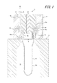
図1に示す本発明の一実施の形態である液体ブロー成形装置1は、本発明の一実施の形態である液体ブロー成形方法によって樹脂製のプリフォーム10を所定形状の容器に液体ブロー成形して当該容器を製造するものである。なお、液体ブロー成形とは、プリフォーム10に供給する加圧流体として加圧エアーに替えて加圧した液体を用いたブロー成形のことである。
A liquid blow molding apparatus 1 according to an embodiment of the present invention shown in FIG. 1 performs a liquid blow molding of a resin preform 10 into a container having a predetermined shape by a liquid blow molding method according to an embodiment of the present invention. The container is manufactured. The liquid blow molding is a blow molding using a pressurized liquid instead of the pressurized air as the pressurized fluid supplied to the preform 10.
液体ブロー成形装置1は、例えばブロー成形用の金型等で構成されるブロー成形型11を有している。図1においては一部のみを示すが、このブロー成形型11のキャビティ12はボトル形状となっており、ブロー成形型11の上面において上方に向けて開口している。詳細は図示しないが、ブロー成形型11は左右に型開きすることができるようになっており、ブロー成形型11を開くことで成形後の製品をブロー成形型11から取り出すことができる。
The liquid blow molding apparatus 1 has a blow molding die 11 composed of, for example, a blow molding die. Although only a part is shown in FIG. 1, the cavity 12 of the blow mold 11 has a bottle shape and opens upward on the upper surface of the blow mold 11. Although details are not shown, the blow mold 11 can be opened left and right, and the molded product can be taken out from the blow mold 11 by opening the blow mold 11.
プリフォーム10はブロー成形型11に配置され、この液体ブロー成形装置1により液体ブロー成形されて容器に形成される。
The preform 10 is placed in a blow mold 11 and is liquid blow molded by the liquid blow molding apparatus 1 to form a container.
プリフォーム10としては、例えばポリプロピレン(PP)やポリエチレンテレフタレート(PET)等の加熱により延伸性が発現する樹脂材料を、射出成形、圧縮成形、押出成形等の手段により、口部10aと本体部10bとを備えた有底筒状(略試験管状)に形成したものを用いることができる。このようなプリフォーム10は、延伸性を発現する所定の温度にまで予め加熱され、その状態で口部10aをキャビティ12から上方に突出させた起立姿勢でブロー成形型11に配置される。
As the preform 10, for example, a resin material that exhibits stretchability by heating, such as polypropylene (PP) or polyethylene terephthalate (PET), is formed by means of injection molding, compression molding, extrusion molding, or the like. Can be used that is formed into a bottomed cylindrical shape (substantially test tube). Such a preform 10 is preheated to a predetermined temperature that exhibits stretchability, and is placed in the blow mold 11 in an upright posture in which the mouth portion 10a protrudes upward from the cavity 12.
なお、プリフォーム10は、1種類の樹脂材料のみで形成された単層構造に限らず、複数種類の樹脂材料を積層した積層構造のものとすることもできる。この場合、複数の樹脂層が互いに接着された構成とすることができるが、それ以外にも、外側層と内側層とを異材質で形成して、お互いが接着しないように積層した積層構造や、当該積層構造において外側層と内側層との間に接着層を軸方向帯状に設けた積層構造のものとすることもできる。このようにプリフォーム10を互いに接着させない積層構造とした場合には、当該プリフォーム10を液体ブロー成形装置1により、所定形状の積層剥離容器に形成することができる。なお、積層構造のプリフォーム10としては、上記のものに限らず、どのような層構成としてもよい。
Note that the preform 10 is not limited to a single layer structure formed of only one type of resin material, but may have a stacked structure in which a plurality of types of resin materials are stacked. In this case, a plurality of resin layers can be bonded to each other, but in addition to this, a laminated structure in which the outer layer and the inner layer are formed of different materials and stacked so as not to adhere to each other The laminated structure may have a laminated structure in which an adhesive layer is provided in an axial band between the outer layer and the inner layer. Thus, when it is set as the laminated structure which does not mutually adhere the preform 10, the said preform 10 can be formed in the lamination peeling container of a predetermined shape with the liquid blow molding apparatus 1. FIG. The preform 10 having a laminated structure is not limited to the above, and any layer structure may be used.
ブロー成形型11の上側には、ブロー成形型11に対して上下方向に相対移動自在にノズルユニット13が設けられている。ノズルユニット13は本体ブロック14とブローノズル15とを有している。
A nozzle unit 13 is provided on the upper side of the blow mold 11 so as to be movable relative to the blow mold 11 in the vertical direction. The nozzle unit 13 has a main body block 14 and a blow nozzle 15.
ブローノズル15は、プリフォーム10の口部10aの内径よりも小径の円筒状に形成されたノズル本体15aとこのノズル本体15aと一体に形成された大径の挟持部15bとが、例えば鋼材や樹脂材料等により一体に形成された構成となっており、挟持部15bが本体ブロック14の内面に嵌め込まれることにより本体ブロック14に固定されている。
The blow nozzle 15 includes a nozzle body 15a formed in a cylindrical shape having a smaller diameter than the inner diameter of the mouth portion 10a of the preform 10 and a large-diameter clamping portion 15b formed integrally with the nozzle body 15a. The structure is integrally formed of a resin material or the like, and the clamping portion 15 b is fixed to the main body block 14 by being fitted into the inner surface of the main body block 14.
ノズル本体15aは、ブロー成形型11のキャビティ12と同軸に配置されており、ノズルユニット13が所定位置にまで下降するとブロー成形型11に装着されたプリフォーム10の口部10aに係合するようになっている。なお、符号16はノズル本体15aと口部10aとの間を密封するシール体である。
The nozzle body 15a is disposed coaxially with the cavity 12 of the blow mold 11 so that when the nozzle unit 13 is lowered to a predetermined position, the nozzle body 15a engages with the mouth portion 10a of the preform 10 attached to the blow mold 11. It has become. Reference numeral 16 denotes a seal body that seals between the nozzle body 15a and the mouth portion 10a.
本体ブロック14の内部にはノズル本体15aと同軸となって上下方向に延びる供給路17が設けられており、この供給路17はその下端においてブローノズル15に接続されている。
Inside the main body block 14 is provided a supply path 17 which is coaxial with the nozzle main body 15a and extends in the vertical direction, and this supply path 17 is connected to the blow nozzle 15 at the lower end thereof.
供給路17には配管18を介して加圧液体供給部19が接続されている。加圧液体供給部19は、配管18を介して供給路17に所定の圧力にまで加圧した液体を供給することができる。加圧液体供給部19から供給路17に加圧した液体が供給されると、当該液体は供給路17からブローノズル15を介してブロー成形型11に配置されたプリフォーム10の内部に供給され、当該プリフォーム10がブロー成形型11のキャビティ12に沿った形状の容器に液体ブロー成形されることになる。
A pressurized liquid supply unit 19 is connected to the supply path 17 via a pipe 18. The pressurized liquid supply unit 19 can supply liquid pressurized to a predetermined pressure to the supply path 17 via the pipe 18. When the pressurized liquid is supplied from the pressurized liquid supply unit 19 to the supply path 17, the liquid is supplied from the supply path 17 to the inside of the preform 10 disposed in the blow mold 11 through the blow nozzle 15. The preform 10 is liquid blow molded into a container having a shape along the cavity 12 of the blow mold 11.
加圧液体供給部19としては、例えば加圧源としてプランジャーポンプを用いた構成のものを用いるのが好ましいが、プリフォーム10の内部に所定の圧力に加圧した液体を供給することができるものであれば、他の構成のものを用いることもできる。
As the pressurized liquid supply unit 19, for example, a configuration using a plunger pump as a pressurizing source is preferably used, but a liquid pressurized to a predetermined pressure can be supplied into the preform 10. Any other configuration can be used.
供給路17の内部には、この供給路17をブローノズル15に対して開閉するため、つまり供給路17とブローノズル15との間で流路を開閉するためにシール部材20が配置されている。シール部材20は、供給路17の軸心に沿って延びる円柱状に形成されており、供給路17の内部で本体ブロック14に対して上下方向に相対移動自在となっている。これに対して、ブローノズル15の挟持部15bの上面にはテーパ状の閉塞面15cが設けられている。シール部材20が下方のストローク端にまで移動してシール部材20の下端に設けられたテーパ面20aが閉塞面15cに当接すると、供給路17とノズル本体15aとの連通がシール部材20によって遮断され、供給路17はブローノズル15に対して閉塞された状態とされる。一方、シール部材20が上方に移動してシール部材20の下端に設けられたテーパ面20aが閉塞面15cから離間すると、供給路17とノズル本体15aとが連通され、供給路17はブローノズル15に対して開かれた状態つまり開放状態とされる。
Inside the supply path 17, a seal member 20 is arranged to open and close the supply path 17 with respect to the blow nozzle 15, that is, to open and close the flow path between the supply path 17 and the blow nozzle 15. . The seal member 20 is formed in a columnar shape extending along the axis of the supply path 17 and is relatively movable in the vertical direction with respect to the main body block 14 inside the supply path 17. On the other hand, a tapered closing surface 15c is provided on the upper surface of the sandwiching portion 15b of the blow nozzle 15. When the sealing member 20 moves to the lower stroke end and the tapered surface 20a provided at the lower end of the sealing member 20 contacts the closing surface 15c, the communication between the supply path 17 and the nozzle body 15a is blocked by the sealing member 20. Then, the supply path 17 is closed with respect to the blow nozzle 15. On the other hand, when the sealing member 20 moves upward and the tapered surface 20a provided at the lower end of the sealing member 20 is separated from the closing surface 15c, the supply path 17 and the nozzle body 15a are communicated, and the supply path 17 is connected to the blow nozzle 15. Are opened, that is, opened.
したがって、図2に示すように、ノズル本体15aをプリフォーム10の口部10aに係合させ、シール部材20を開いて供給路17をブローノズル15に連通させた状態で加圧液体供給部19を作動させることで、加圧液体供給部19から供給路17及びブローノズル15を介してプリフォーム10内に加圧した液体を供給して、当該プリフォーム10を液体ブロー成形することができる。
Therefore, as shown in FIG. 2, the pressurized liquid supply unit 19 is engaged with the nozzle body 15 a engaged with the mouth portion 10 a of the preform 10, the seal member 20 is opened, and the supply path 17 is communicated with the blow nozzle 15. , The pressurized liquid is supplied into the preform 10 from the pressurized liquid supply section 19 via the supply path 17 and the blow nozzle 15, and the preform 10 can be subjected to liquid blow molding.
液体ブロー成形装置1は、シール部材20の中央部に形成された挿通孔に延伸ロッド22が摺動自在に装着された構成とすることもできる。この場合、延伸ロッド22はシール部材20に対して上下方向(軸方向)に相対移動可能となっており、図2に示すように、シール部材20に対して下方(キャビティ12の底部)に向けて移動することにより、ブロー成形型11に配置されたプリフォーム10の本体部10bの底部分を下方に向けて押し下げて、当該本体部10bをキャビティ12の内部において軸方向(縦方向)に延伸させる。つまり、延伸ロッド22が設けられた場合には、液体ブロー成形装置1は、ブロー成形型11に配置されたプリフォーム10を、延伸ロッド22を用いて縦方向に延伸させつつ加圧した液体で径方向に延伸させる二軸延伸ブロー成形を行うように構成される。
The liquid blow molding apparatus 1 may be configured such that the extending rod 22 is slidably mounted in the insertion hole formed in the central portion of the seal member 20. In this case, the extending rod 22 is movable relative to the seal member 20 in the vertical direction (axial direction), and is directed downward (bottom of the cavity 12) with respect to the seal member 20 as shown in FIG. The bottom portion of the main body portion 10b of the preform 10 disposed in the blow mold 11 is pushed downward to extend the main body portion 10b in the axial direction (longitudinal direction) inside the cavity 12. Let That is, in the case where the stretching rod 22 is provided, the liquid blow molding apparatus 1 uses a liquid that is pressurized while stretching the preform 10 disposed in the blow molding die 11 in the longitudinal direction using the stretching rod 22. It is configured to perform biaxial stretch blow molding that extends in the radial direction.
なお、加圧液体供給部19、シール部材20及び延伸ロッド22は、図示しない制御装置によりその作動ないし作動タイミング等が統合制御されるようになっている。
In addition, the operation | movement thru | or operation timing of the pressurized liquid supply part 19, the sealing member 20, and the extending | stretching rod 22 are integratedly controlled by the control apparatus which is not shown in figure.
上述のように、液体ブロー成形装置1は、ノズル本体15aをプリフォーム10の口部10aに係合させた状態で、シール部材20を開放して供給路17をブローノズル15に連通させ、加圧液体供給部19から供給路17に加圧した液体を供給することで、ブローノズル15を介して加圧した液体をプリフォーム10に供給して液体ブロー成形を行うようになっているが、その際、シール部材20の開放が開始された(シール部材20の開動作が開始された)後に、加圧液体供給部19による供給路17への加圧した液体の供給を開始させるようにしている。つまり、本発明の液体ブロー成形装置1では、シール部材20の開放が開始されるのと同時に加圧液体供給部19による供給路17への加圧した液体の供給を開始するのではなく、シール部材20の開放が開始された後に、加圧液体供給部19による供給路17への加圧した液体の供給を開始させるようにしている。これにより、シール部材20が開く前に加圧液体供給部19によって供給路17内の液体が所定値を超えて加圧されることを防止し、シール部材20が十分に液体を流すことができる開度にまで開かれたときにプリフォーム10内に当該液体が所望の圧力で供給されるようにして、プリフォーム10内への液体の供給初期における当該液体の挙動を安定化させ、当該プリフォーム10の成形性を高めることができる。
As described above, in the state where the nozzle body 15a is engaged with the mouth portion 10a of the preform 10, the liquid blow molding apparatus 1 opens the seal member 20 and allows the supply path 17 to communicate with the blow nozzle 15, thereby adding pressure. By supplying pressurized liquid from the pressurized liquid supply unit 19 to the supply path 17, the pressurized liquid is supplied to the preform 10 through the blow nozzle 15, and liquid blow molding is performed. At that time, after the opening of the seal member 20 is started (the opening operation of the seal member 20 is started), supply of the pressurized liquid to the supply path 17 by the pressurized liquid supply unit 19 is started. Yes. That is, in the liquid blow molding apparatus 1 of the present invention, the supply of the pressurized liquid to the supply passage 17 by the pressurized liquid supply unit 19 is not started at the same time when the opening of the seal member 20 is started, but the seal After the opening of the member 20 is started, supply of the pressurized liquid to the supply path 17 by the pressurized liquid supply unit 19 is started. Thereby, before the seal member 20 opens, the pressurized liquid supply part 19 prevents the liquid in the supply path 17 from being pressurized beyond a predetermined value, and the seal member 20 can sufficiently flow the liquid. The liquid is supplied to the preform 10 at a desired pressure when the opening is opened to stabilize the behavior of the liquid at the initial stage of supplying the liquid into the preform 10. The formability of the reform 10 can be improved.
なお、シール部材20は、その開動作が開始されるのと同時にその開放が開始される構成とされるのが好ましいが、開動作が開始されてから一定時間経過後に開放が開始される構成のものであってもよい。この場合、加圧液体供給部19は、シール部材20が開動作を開始したときを基準とするのではなく、シール部材20が実際に供給路17をブローノズル15に対して開放し始めたときを基準として、供給路17への加圧した液体の供給を開始させることになる。
The seal member 20 is preferably configured to start opening at the same time as the opening operation thereof is started. However, the seal member 20 is configured to start opening after a predetermined time has elapsed since the opening operation started. It may be a thing. In this case, the pressurized liquid supply unit 19 is not based on the time when the seal member 20 starts to open, but when the seal member 20 actually starts to open the supply path 17 to the blow nozzle 15. As a reference, supply of pressurized liquid to the supply path 17 is started.
上記のように、プリフォーム10内への供給初期における液体の挙動を安定化させてプリフォーム10の成形性を高めるためには、シール部材20の開放を開始してから、加圧液体供給部19による供給路17への加圧した液体の供給を開始するまでの時間を、0.01秒以上、0.05秒以下とするのが好ましい。当該時間を0.01秒未満とした場合には、加圧液体供給部19が供給路17への加圧した液体の供給を開始したときのシール部材20の開度が未だ小さく、供給路17内の液体が所定値を僅かに超えて加圧されてプリフォーム10の成形性が若干低下することになる。一方、当該時間を0.05秒より大きくした場合には、プリフォーム10が加圧した液体によって液体ブロー成形される前に、当該プリフォーム10の内部に流入する加圧されていない液体の量が多くなって、当該液体により加熱状態のプリフォーム10が冷却されてその成形性が低下することになる。よって、上記のように、シール部材20の開放を開始してから、加圧液体供給部19による供給路17への加圧した液体の供給を開始するまでの時間は、0.01秒以上、0.05秒以下とするのが好ましい。
As described above, in order to stabilize the behavior of the liquid at the initial stage of supply into the preform 10 and improve the moldability of the preform 10, the pressurized liquid supply section is started after the opening of the seal member 20 is started. It is preferable that the time until the supply of the pressurized liquid to the supply path 17 by 19 is started is 0.01 seconds or more and 0.05 seconds or less. When the time is less than 0.01 seconds, the opening degree of the seal member 20 when the pressurized liquid supply unit 19 starts supplying pressurized liquid to the supply path 17 is still small, and the supply path 17 The liquid inside is pressurized slightly above the predetermined value, and the moldability of the preform 10 is slightly lowered. On the other hand, if the time is longer than 0.05 seconds, the amount of unpressurized liquid that flows into the preform 10 before the preform 10 is subjected to liquid blow molding with the pressurized liquid. As a result, the preform 10 in a heated state is cooled by the liquid, and its moldability is lowered. Therefore, as described above, the time from the start of the opening of the seal member 20 to the start of the supply of the pressurized liquid to the supply path 17 by the pressurized liquid supply unit 19 is 0.01 seconds or more, It is preferable that the time be 0.05 seconds or less.
また、よりプリフォーム10の成形性を高めるためには、シール部材20の開放を開始してから、加圧液体供給部19による供給路17への加圧した液体の供給を開始するまでの時間を、0.01秒以上、0.03秒以下とするのが好ましい。当該時間が0.03秒を超える場合は、供給路17内の圧力上昇による成形性(賦形性を含む)の低下を避けることはできるが、プリフォーム10が加圧された液体によって液体ブロー成形される前に、当該プリフォーム10の内部に流入する加圧されていない液体の量が多くなって、当該液体により加熱状態のプリフォームが冷却されてその成形性が低下し、容器の成形後収縮が大きくなることで満注容量が減少することになる。また、過度の冷却により容器の芯ずれにもつながる。当該時間を0.03秒以下とした場合には、プリフォーム10が加圧した液体によって液体ブロー成形される前に、当該プリフォーム10の内部に流入する加圧されていない液体の量をプリフォーム10に対する冷却の影響を実質的に無くす程度に少なくすることができるので、当該液体により加熱状態のプリフォーム10が冷却されて成形性が低下することを防止して、その成形性をより高めることができる。
In order to further improve the moldability of the preform 10, the time from the start of the opening of the seal member 20 to the start of the supply of pressurized liquid to the supply path 17 by the pressurized liquid supply unit 19. Is preferably 0.01 seconds or more and 0.03 seconds or less. When the time exceeds 0.03 seconds, it is possible to avoid a decrease in formability (including formability) due to an increase in pressure in the supply passage 17, but the liquid is blown by the pressurized liquid of the preform 10. Before molding, the amount of unpressurized liquid that flows into the preform 10 increases, and the preform is cooled by the liquid and the moldability of the preform is lowered. Increased post-shrinkage will reduce the full capacity. In addition, excessive cooling leads to misalignment of the container. When the time is set to 0.03 seconds or less, the amount of the non-pressurized liquid flowing into the preform 10 is increased before the preform 10 is liquid blow molded by the pressurized liquid. Since the effect of cooling on the reform 10 can be substantially eliminated, the preform 10 in the heated state is cooled by the liquid to prevent the moldability from being lowered, and the moldability is further improved. be able to.
なお、加圧されない液体がプリフォーム10に供給されることにより当該プリフォーム10が冷却されて成形性が低下する問題は、例えばプリフォーム10に供給する液体の温度が常温(例えば20℃)や低温(10℃以下)の場合等、プリフォーム10の加熱温度(余熱温度)よりも低温の液体を用いるときに顕著に生じることになるが、当該液体の温度をプリフォーム10に冷却を生じさせない程度の温度にまで高めることによって解消することができる。
In addition, the problem that the preform 10 is cooled when the liquid that is not pressurized is supplied to the preform 10 and the moldability is deteriorated is, for example, that the temperature of the liquid supplied to the preform 10 is normal temperature (for example, 20 ° C.) In the case of a low temperature (10 ° C. or lower) or the like, it will occur remarkably when a liquid having a temperature lower than the heating temperature (preheating temperature) of the preform 10 is used. It can be solved by raising the temperature to a certain level.
次に、本発明の効果を確認するために、樹脂製のプリフォームに所定の圧力にまで加圧した常温(20℃)の水を供給することにより当該プリフォームを液体ブロー成形して内容量360ml用として使用されるボトル形状の容器を成形する場合について、シール部材の開動作を開始してから、加圧液体供給部による供給路への加圧した液体の供給を開始するまでの時間を種々変更して液体ブロー成形を行う試験を行い、その成形性についての評価を行った。その評価結果を表1に示す。
Next, in order to confirm the effect of the present invention, the preform is liquid blow-molded by supplying water at room temperature (20 ° C.) pressurized to a predetermined pressure to the resin-made preform. In the case of forming a bottle-shaped container used for 360 ml, the time from the start of the opening operation of the seal member to the start of the supply of pressurized liquid to the supply path by the pressurized liquid supply unit Various tests were performed to perform liquid blow molding, and the moldability was evaluated. The evaluation results are shown in Table 1.

表1において、「加圧液体供給部の作動タイミング」の欄は、シール部材の開放を開始してから加圧液体供給部が供給路に加圧した液体の供給を開始するまでの時間(秒)を示す。なお、当該欄において「0」は、シール部材の開放を開始するのと同時に加圧液体供給部が供給路への加圧した液体の供給を開始した場合を示す。また、「シール部材の開度」の欄は、シール部材が開かれることにより生じる供給路とブローノズルとの間を連通させる流路の有効断面積を当該流路が全開のときに対する百分率(%)で示す。「0」は当該流路が全閉であることを示し、「100」は当該流路が全開であることを示す。さらに、「供給初期の供給路内の圧力上昇」の欄は、加圧液体供給部が供給路への加圧した液体の供給を開始した初期段階におけるプリフォームに供給される液体の圧力であり、「あり」は所定値(加圧液体供給部により設定された値)を超えた圧力であることを示し、「なし」は所定値を超えない状態を示す。また、「芯ずれ」の欄には、成形後の容器における芯ずれの有無の評価結果を示す。さらに、成形後の容器の物性値として、当該容器の満注容量(注入可能な液体の量)の3回分の測定結果及びその平均値を示す。
In Table 1, the column “Operation Timing of Pressurized Liquid Supply Unit” indicates the time (seconds) from the start of opening the seal member until the pressurized liquid supply unit starts supplying the pressurized liquid to the supply path. ). In this column, “0” indicates a case where the pressurized liquid supply unit starts supplying pressurized liquid to the supply path at the same time when opening of the seal member is started. In the column of “opening degree of seal member”, the effective cross-sectional area of the flow path that communicates between the supply path and the blow nozzle generated by opening the seal member is expressed as a percentage (% ). “0” indicates that the channel is fully closed, and “100” indicates that the channel is fully open. Further, the column “Increase in pressure in the supply channel at the initial supply stage” is the pressure of the liquid supplied to the preform at the initial stage when the pressurized liquid supply unit starts supplying pressurized liquid to the supply channel. , “Present” indicates that the pressure exceeds a predetermined value (a value set by the pressurized liquid supply unit), and “none” indicates a state where the predetermined value is not exceeded. The column “center misalignment” shows the evaluation result of the presence or absence of misalignment in the molded container. Furthermore, as a physical property value of the molded container, a measurement result for three times of the full injection capacity (amount of liquid that can be injected) and an average value thereof are shown.
表1の評価結果から、加圧液体供給部の作動タイミングが0(秒)つまりシール部材の開放を開始するのと同時に加圧液体供給部が供給路への加圧した液体の供給を開始した場合では、供給初期段階におけるプリフォームに供給される液体の圧力上昇が生じ、成形後の容器に芯ずれが生じるのに対して、シール部材の開放を開始した後に、加圧液体供給部の供給路への加圧した液体の供給を開始させた場合では、前記圧力上昇が生じず、つまり当該圧力上昇に起因する成形性の低下が生じずにその成形性を高められることが確認できた。
From the evaluation results in Table 1, the operation timing of the pressurized liquid supply unit is 0 (seconds), that is, the start of the release of the seal member is started, and at the same time, the pressurized liquid supply unit starts supplying pressurized liquid to the supply path. In some cases, the pressure of the liquid supplied to the preform in the initial supply stage is increased, and the container after molding is misaligned. On the other hand, the supply of the pressurized liquid supply unit is started after the seal member is opened. It was confirmed that when the supply of pressurized liquid to the passage was started, the pressure increase did not occur, that is, the moldability could be improved without causing a decrease in moldability due to the pressure increase.
特に、加圧液体供給部の作動タイミングを、シール部材の開放を開始してから0.01(秒)以上とした場合には、加圧液体供給部が供給路への加圧した液体の供給を開始したときのシール部材の開度を十分に確保して、高い成形性を確保できることが確認できた。また、本試験のように加圧流体として常温(20℃)の水を用いた場合であっても、加圧液体供給部の作動タイミングを、シール部材の開放を開始してから0.05(秒)以下とすれば、芯ずれを生じさせずに高い成形性を維持できることが確認できた。これらの結果から、加圧液体供給部の作動タイミングを、シール部材の開放を開始してから0.01(秒)以上、0.05(秒)以下とすれば、より好ましいことが確認できた。
In particular, when the operation timing of the pressurized liquid supply unit is set to 0.01 (seconds) or more after the opening of the seal member is started, the pressurized liquid supply unit supplies the pressurized liquid to the supply path. It was confirmed that the opening degree of the seal member when starting the process can be sufficiently secured to ensure high moldability. Further, even when water at room temperature (20 ° C.) is used as the pressurized fluid as in this test, the operation timing of the pressurized liquid supply unit is set to 0.05 ( It was confirmed that a high formability could be maintained without causing misalignment. From these results, it was confirmed that the operation timing of the pressurized liquid supply unit is more preferably 0.01 (second) or more and 0.05 (second) or less after the opening of the seal member is started. .
なお、加圧液体供給部の作動タイミングがシール部材の開放を開始してから0.06(秒)の場合、前記圧力上昇による成形性の低下は生じないが、プリフォームが液体ブロー成形される前に当該プリフォームの内部に流入する加圧されていない液体の量が多くなってプリフォームが冷却され、これにより芯ずれを生じるなどその成形性が低下することになる。この場合、容器に成形不良が生じるため、その満注容量の測定は省略した。
When the operation timing of the pressurized liquid supply unit is 0.06 (seconds) after the opening of the seal member is started, the moldability is not deteriorated due to the pressure increase, but the preform is liquid blow molded. The amount of unpressurized liquid that flows into the preform before is increased, and the preform is cooled, thereby causing misalignment such as misalignment. In this case, since the molding defect occurred in the container, the measurement of the full capacity was omitted.
また、表1の評価結果から、加圧液体供給部の作動タイミングを、シール部材の開放を開始してから0.01秒以上、0.03秒以下とした場合、加圧液体供給部の作動タイミングが0(秒)つまりシール部材の開放が開始されるのと同時に加圧液体供給部が供給路への加圧した液体の供給を開始した場合に対して、成形後の容器の満注容量が増大していることが解る。このことから、加圧液体供給部の作動タイミングを、0.01秒以上、0.03秒以下とした場合には、より良好なプリフォームの成形性を得られることが確認できた。
Further, from the evaluation results in Table 1, when the operation timing of the pressurized liquid supply unit is set to 0.01 seconds or more and 0.03 seconds or less after the opening of the seal member is started, the operation of the pressurized liquid supply unit is performed. When the timing is 0 (seconds), that is, when the pressurized liquid supply unit starts supplying pressurized liquid to the supply passage at the same time as the opening of the seal member is started, the full capacity of the molded container It can be seen that is increasing. From this, it was confirmed that when the operation timing of the pressurized liquid supply unit was set to 0.01 seconds or more and 0.03 seconds or less, better moldability of the preform could be obtained.
本発明は前記実施の形態に限定されるものではなく、その要旨を逸脱しない範囲で種々変更可能であることはいうまでもない。
It goes without saying that the present invention is not limited to the above-described embodiment, and various modifications can be made without departing from the scope of the invention.
例えば、シール部材20が開放を開始した後、加圧液体供給部19が供給路17への加圧した液体の供給を開始するまでの時間は、上記数値範囲に限らず、任意に設定することができる。
For example, the time from when the seal member 20 starts to open until the pressurized liquid supply unit 19 starts supplying pressurized liquid to the supply path 17 is not limited to the above numerical range, and may be arbitrarily set. Can do.
また、シール部材20は上記した構成に限らず、供給路17に設けられて当該供給路17をブローノズル15に対して開閉することができるものであれば種々の構成のものを採用することができる。
Further, the seal member 20 is not limited to the above-described configuration, and various configurations may be adopted as long as the seal member 20 is provided in the supply passage 17 and can open and close the supply passage 17 with respect to the blow nozzle 15. it can.
さらに、液体ブロー成形装置1は、延伸ロッド22が設けられない構成とすることもできる。
Furthermore, the liquid blow molding apparatus 1 may be configured such that the stretching rod 22 is not provided.
1 液体ブロー成形装置
10 プリフォーム
10a 口部
10b 本体部
11 ブロー成形型
12 キャビティ
13 ノズルユニット
14 本体ブロック
15 ブローノズル
15a ノズル本体
15b 挟持部
15c 閉塞面
16 シール体
17 供給路
18 配管
19 加圧液体供給部
20 シール部材
20a テーパ面
22 延伸ロッド DESCRIPTION OF SYMBOLS 1 Liquidblow molding apparatus 10 Preform 10a Mouth part 10b Main body part 11 Blow molding die 12 Cavity 13 Nozzle unit 14 Main body block 15 Blow nozzle 15a Nozzle main body 15b Nipping part 15c Closure surface 16 Sealing body 17 Supply path 18 Piping 19 Pressurized liquid Supply unit 20 Seal member 20a Tapered surface 22 Stretched rod
10 プリフォーム
10a 口部
10b 本体部
11 ブロー成形型
12 キャビティ
13 ノズルユニット
14 本体ブロック
15 ブローノズル
15a ノズル本体
15b 挟持部
15c 閉塞面
16 シール体
17 供給路
18 配管
19 加圧液体供給部
20 シール部材
20a テーパ面
22 延伸ロッド DESCRIPTION OF SYMBOLS 1 Liquid
Claims (7)
- 樹脂製のプリフォームを所定形状の容器に液体ブロー成形する液体ブロー成形装置であって、
前記プリフォームが配置されるブロー成形型と、
前記プリフォームの口部に係合するブローノズルと、
前記ブローノズルに接続される供給路に加圧した液体を供給する加圧液体供給部と、
前記供給路に設けられ、前記供給路を前記ブローノズルに対して開閉するシール部材とを有し、
前記シール部材の開放が開始された後に、前記加圧液体供給部が前記供給路への加圧した液体の供給を開始することを特徴とする液体ブロー成形装置。 A liquid blow molding device for liquid blow molding a resin preform into a container having a predetermined shape,
A blow mold in which the preform is disposed;
A blow nozzle engaged with the mouth of the preform;
A pressurized liquid supply unit for supplying pressurized liquid to a supply path connected to the blow nozzle;
A seal member that is provided in the supply path and opens and closes the supply path with respect to the blow nozzle;
The liquid blow molding apparatus, wherein after the opening of the seal member is started, the pressurized liquid supply unit starts supplying pressurized liquid to the supply path. - 前記シール部材の開放が開始されてから、前記加圧液体供給部が前記供給路への加圧した液体の供給を開始するまでの時間を、0.01秒以上、0.05秒以下とする、請求項1に記載の液体ブロー成形装置。 The time from when the opening of the seal member is started to when the pressurized liquid supply unit starts supplying pressurized liquid to the supply path is 0.01 seconds or more and 0.05 seconds or less. The liquid blow molding apparatus according to claim 1.
- 前記シール部材の開放が開始されてから、前記加圧液体供給部が前記供給路への加圧した液体の供給を開始するまでの時間を、0.01秒以上、0.03秒以下とする、請求項1に記載の液体ブロー成形装置。 The time from when the opening of the seal member is started to when the pressurized liquid supply unit starts supplying pressurized liquid to the supply path is 0.01 seconds or more and 0.03 seconds or less. The liquid blow molding apparatus according to claim 1.
- 前記プリフォームを縦方向に延伸するための延伸ロッドを備える、請求項1~3の何れか1項に記載の液体ブロー成形装置。 4. The liquid blow molding apparatus according to claim 1, further comprising a stretching rod for stretching the preform in a longitudinal direction.
- 樹脂製のプリフォームを所定形状の容器に液体ブロー成形する液体ブロー成形方法であって、
前記プリフォームが配置されるブロー成形型と、
前記プリフォームの口部に係合するブローノズルと、
前記ブローノズルに接続される供給路に加圧した液体を供給する加圧液体供給部と、
前記供給路に設けられ、前記供給路を前記ブローノズルに対して開閉するシール部材とを有する液体ブロー成形装置を用い、
前記シール部材の開放が開始された後に、前記加圧液体供給部が前記供給路への加圧した液体の供給を開始することを特徴とする液体ブロー成形方法。 A liquid blow molding method in which a resin preform is liquid blow molded into a container having a predetermined shape,
A blow mold in which the preform is disposed;
A blow nozzle engaged with the mouth of the preform;
A pressurized liquid supply unit for supplying pressurized liquid to a supply path connected to the blow nozzle;
Using a liquid blow molding device provided in the supply path and having a seal member that opens and closes the supply path with respect to the blow nozzle,
The liquid blow molding method, wherein after the opening of the seal member is started, the pressurized liquid supply unit starts supplying pressurized liquid to the supply path. - 前記シール部材の開放が開始されてから、前記加圧液体供給部が前記供給路への加圧した液体の供給を開始するまでの時間を、0.01秒以上、0.05秒以下とする、請求項5に記載の液体ブロー成形方法。 The time from when the opening of the seal member is started to when the pressurized liquid supply unit starts supplying pressurized liquid to the supply path is 0.01 seconds or more and 0.05 seconds or less. The liquid blow molding method according to claim 5.
- 前記シール部材の開放が開始されてから、前記加圧液体供給部が前記供給路への加圧した液体の供給を開始するまでの時間を、0.01秒以上、0.03秒以下とする、請求項5に記載の液体ブロー成形方法。 The time from when the opening of the seal member is started to when the pressurized liquid supply unit starts supplying pressurized liquid to the supply path is 0.01 seconds or more and 0.03 seconds or less. The liquid blow molding method according to claim 5.
Priority Applications (4)
| Application Number | Priority Date | Filing Date | Title |
|---|---|---|---|
| EP16786125.1A EP3292985B1 (en) | 2015-04-30 | 2016-04-18 | Liquid blow molding apparatus and liquid blow molding method |
| CN201680025295.5A CN107848188B (en) | 2015-04-30 | 2016-04-18 | Liquid blow molding device and liquid blow molding method |
| US15/570,208 US11155016B2 (en) | 2015-04-30 | 2016-04-18 | Liquid blow molding apparatus and liquid blow molding method |
| US17/510,339 US20220040901A1 (en) | 2015-04-30 | 2021-10-25 | Liquid blow molding apparatus |
Applications Claiming Priority (2)
| Application Number | Priority Date | Filing Date | Title |
|---|---|---|---|
| JP2015-093651 | 2015-04-30 | ||
| JP2015093651A JP6450641B2 (en) | 2015-04-30 | 2015-04-30 | Liquid blow molding apparatus and liquid blow molding method |
Related Child Applications (2)
| Application Number | Title | Priority Date | Filing Date |
|---|---|---|---|
| US15/570,208 A-371-Of-International US11155016B2 (en) | 2015-04-30 | 2016-04-18 | Liquid blow molding apparatus and liquid blow molding method |
| US17/510,339 Division US20220040901A1 (en) | 2015-04-30 | 2021-10-25 | Liquid blow molding apparatus |
Publications (1)
| Publication Number | Publication Date |
|---|---|
| WO2016174846A1 true WO2016174846A1 (en) | 2016-11-03 |
Family
ID=57199251
Family Applications (1)
| Application Number | Title | Priority Date | Filing Date |
|---|---|---|---|
| PCT/JP2016/002074 WO2016174846A1 (en) | 2015-04-30 | 2016-04-18 | Liquid blow molding apparatus and liquid blow molding method |
Country Status (5)
| Country | Link |
|---|---|
| US (2) | US11155016B2 (en) |
| EP (1) | EP3292985B1 (en) |
| JP (1) | JP6450641B2 (en) |
| CN (1) | CN107848188B (en) |
| WO (1) | WO2016174846A1 (en) |
Cited By (2)
| Publication number | Priority date | Publication date | Assignee | Title |
|---|---|---|---|---|
| WO2018079012A1 (en) * | 2016-10-28 | 2018-05-03 | 株式会社吉野工業所 | Liquid blow-molding method |
| US10940631B2 (en) | 2016-10-28 | 2021-03-09 | Yoshino Kogyosho Co., Ltd. | Liquid blow molding method |
Citations (5)
| Publication number | Priority date | Publication date | Assignee | Title |
|---|---|---|---|---|
| JPH1076568A (en) * | 1996-09-05 | 1998-03-24 | Mitsubishi Plastics Ind Ltd | Method of blow molding |
| WO2003095179A1 (en) * | 2002-05-03 | 2003-11-20 | Nestle Waters Management & Technology (Societe Anonyme) | Method of producing a polyester resin container and device for performing same |
| WO2013117492A1 (en) * | 2012-02-10 | 2013-08-15 | Nestec S.A. | A method of blowing, filling and capping containers |
| JP2013154617A (en) * | 2012-01-31 | 2013-08-15 | Yoshino Kogyosho Co Ltd | Blow molding device |
| JP2014008636A (en) * | 2012-06-28 | 2014-01-20 | Yoshino Kogyosho Co Ltd | Method for positively pressurizing vessel inside and filling vessel |
Family Cites Families (8)
| Publication number | Priority date | Publication date | Assignee | Title |
|---|---|---|---|---|
| FR1031320A (en) * | 1951-01-23 | 1953-06-23 | Raint Gobain | Process for the continuous production of hollow articles in thermoplastic material |
| US8740609B2 (en) * | 2011-06-09 | 2014-06-03 | Amcor Limited | CSD cooling and pressurization to keep CO2 in solution during forming |
| EP2810763B1 (en) * | 2012-01-31 | 2018-03-07 | Discma AG | Blow molding device |
| JP5829566B2 (en) * | 2012-03-30 | 2015-12-09 | 株式会社吉野工業所 | Blow molding equipment |
| EP2832682B1 (en) * | 2012-03-30 | 2018-07-25 | Discma AG | Method for manufacturing container containing content fluid and blow-molding device |
| WO2014020042A1 (en) * | 2012-08-03 | 2014-02-06 | Nestec S.A. | Method and apparatus for fabricating containers |
| JP5870001B2 (en) * | 2012-09-28 | 2016-02-24 | 株式会社吉野工業所 | Blow molding apparatus and container manufacturing method |
| JP6230926B2 (en) * | 2014-01-30 | 2017-11-15 | 株式会社吉野工業所 | Blow molding apparatus and blow molding method |
-
2015
- 2015-04-30 JP JP2015093651A patent/JP6450641B2/en active Active
-
2016
- 2016-04-18 CN CN201680025295.5A patent/CN107848188B/en active Active
- 2016-04-18 EP EP16786125.1A patent/EP3292985B1/en active Active
- 2016-04-18 US US15/570,208 patent/US11155016B2/en active Active
- 2016-04-18 WO PCT/JP2016/002074 patent/WO2016174846A1/en active Application Filing
-
2021
- 2021-10-25 US US17/510,339 patent/US20220040901A1/en not_active Abandoned
Patent Citations (5)
| Publication number | Priority date | Publication date | Assignee | Title |
|---|---|---|---|---|
| JPH1076568A (en) * | 1996-09-05 | 1998-03-24 | Mitsubishi Plastics Ind Ltd | Method of blow molding |
| WO2003095179A1 (en) * | 2002-05-03 | 2003-11-20 | Nestle Waters Management & Technology (Societe Anonyme) | Method of producing a polyester resin container and device for performing same |
| JP2013154617A (en) * | 2012-01-31 | 2013-08-15 | Yoshino Kogyosho Co Ltd | Blow molding device |
| WO2013117492A1 (en) * | 2012-02-10 | 2013-08-15 | Nestec S.A. | A method of blowing, filling and capping containers |
| JP2014008636A (en) * | 2012-06-28 | 2014-01-20 | Yoshino Kogyosho Co Ltd | Method for positively pressurizing vessel inside and filling vessel |
Non-Patent Citations (1)
| Title |
|---|
| See also references of EP3292985A4 * |
Cited By (2)
| Publication number | Priority date | Publication date | Assignee | Title |
|---|---|---|---|---|
| WO2018079012A1 (en) * | 2016-10-28 | 2018-05-03 | 株式会社吉野工業所 | Liquid blow-molding method |
| US10940631B2 (en) | 2016-10-28 | 2021-03-09 | Yoshino Kogyosho Co., Ltd. | Liquid blow molding method |
Also Published As
| Publication number | Publication date |
|---|---|
| CN107848188B (en) | 2021-05-07 |
| CN107848188A (en) | 2018-03-27 |
| US11155016B2 (en) | 2021-10-26 |
| US20220040901A1 (en) | 2022-02-10 |
| US20180117826A1 (en) | 2018-05-03 |
| EP3292985B1 (en) | 2020-10-21 |
| JP6450641B2 (en) | 2019-01-09 |
| JP2016210036A (en) | 2016-12-15 |
| EP3292985A1 (en) | 2018-03-14 |
| EP3292985A4 (en) | 2019-01-16 |
Similar Documents
| Publication | Publication Date | Title |
|---|---|---|
| US9987790B2 (en) | Blow molding apparatus | |
| WO2017187698A1 (en) | Liquid blow molding method | |
| WO2017090340A1 (en) | Liquid blow molding method | |
| JP2017510483A (en) | Forming and setting the headspace in the container | |
| JP6685705B2 (en) | Liquid blow molding method and liquid blow molding apparatus | |
| CN109863012B (en) | Liquid blow molding method | |
| US10766183B2 (en) | Liquid blow-molding method for delamination container | |
| US20220040901A1 (en) | Liquid blow molding apparatus | |
| WO2021084834A1 (en) | Liquid blow molding device | |
| US10933573B2 (en) | Liquid blow molding apparatus and liquid blow molding method | |
| WO2018179747A1 (en) | Container manufacturing method | |
| CN109803808B (en) | Liquid blow molding system | |
| JP6840025B2 (en) | Manufacturing method of liquid container | |
| JP6636589B2 (en) | Liquid blow molding apparatus and liquid blow molding method | |
| WO2017168996A1 (en) | Method for producing container by liquid blow molding | |
| WO2016157686A1 (en) | Liquid blow molding apparatus |
Legal Events
| Date | Code | Title | Description |
|---|---|---|---|
| 121 | Ep: the epo has been informed by wipo that ep was designated in this application |
Ref document number: 16786125 Country of ref document: EP Kind code of ref document: A1 |
|
| WWE | Wipo information: entry into national phase |
Ref document number: 15570208 Country of ref document: US |
|
| NENP | Non-entry into the national phase |
Ref country code: DE |
|
| WWE | Wipo information: entry into national phase |
Ref document number: 2016786125 Country of ref document: EP |