WO2016174709A1 - 超音波振動子の製造方法および超音波振動子 - Google Patents
超音波振動子の製造方法および超音波振動子 Download PDFInfo
- Publication number
- WO2016174709A1 WO2016174709A1 PCT/JP2015/062683 JP2015062683W WO2016174709A1 WO 2016174709 A1 WO2016174709 A1 WO 2016174709A1 JP 2015062683 W JP2015062683 W JP 2015062683W WO 2016174709 A1 WO2016174709 A1 WO 2016174709A1
- Authority
- WO
- WIPO (PCT)
- Prior art keywords
- piezoelectric element
- piezoelectric elements
- mechanical quality
- quality factor
- ultrasonic transducer
- Prior art date
Links
- 238000004519 manufacturing process Methods 0.000 title claims abstract description 31
- 230000007423 decrease Effects 0.000 claims description 19
- 238000000034 method Methods 0.000 claims description 11
- 230000020169 heat generation Effects 0.000 description 18
- 230000005540 biological transmission Effects 0.000 description 6
- 230000000694 effects Effects 0.000 description 6
- 230000000052 comparative effect Effects 0.000 description 4
- 238000010586 diagram Methods 0.000 description 4
- 238000001816 cooling Methods 0.000 description 3
- 210000001519 tissue Anatomy 0.000 description 3
- 230000002238 attenuated effect Effects 0.000 description 2
- 230000008602 contraction Effects 0.000 description 2
- 238000002560 therapeutic procedure Methods 0.000 description 2
- 206010037660 Pyrexia Diseases 0.000 description 1
- 229910001069 Ti alloy Inorganic materials 0.000 description 1
- 229910052782 aluminium Inorganic materials 0.000 description 1
- XAGFODPZIPBFFR-UHFFFAOYSA-N aluminium Chemical compound [Al] XAGFODPZIPBFFR-UHFFFAOYSA-N 0.000 description 1
- 210000000988 bone and bone Anatomy 0.000 description 1
- 210000000845 cartilage Anatomy 0.000 description 1
- 238000006243 chemical reaction Methods 0.000 description 1
- 239000012212 insulator Substances 0.000 description 1
- VJPLIHZPOJDHLB-UHFFFAOYSA-N lead titanium Chemical compound [Ti].[Pb] VJPLIHZPOJDHLB-UHFFFAOYSA-N 0.000 description 1
- 239000000463 material Substances 0.000 description 1
- 229910052751 metal Inorganic materials 0.000 description 1
- 239000002184 metal Substances 0.000 description 1
- 239000007769 metal material Substances 0.000 description 1
- 230000001225 therapeutic effect Effects 0.000 description 1
Images

Classifications
-
- B—PERFORMING OPERATIONS; TRANSPORTING
- B06—GENERATING OR TRANSMITTING MECHANICAL VIBRATIONS IN GENERAL
- B06B—METHODS OR APPARATUS FOR GENERATING OR TRANSMITTING MECHANICAL VIBRATIONS OF INFRASONIC, SONIC, OR ULTRASONIC FREQUENCY, e.g. FOR PERFORMING MECHANICAL WORK IN GENERAL
- B06B1/00—Methods or apparatus for generating mechanical vibrations of infrasonic, sonic, or ultrasonic frequency
- B06B1/02—Methods or apparatus for generating mechanical vibrations of infrasonic, sonic, or ultrasonic frequency making use of electrical energy
- B06B1/06—Methods or apparatus for generating mechanical vibrations of infrasonic, sonic, or ultrasonic frequency making use of electrical energy operating with piezoelectric effect or with electrostriction
- B06B1/0607—Methods or apparatus for generating mechanical vibrations of infrasonic, sonic, or ultrasonic frequency making use of electrical energy operating with piezoelectric effect or with electrostriction using multiple elements
- B06B1/0611—Methods or apparatus for generating mechanical vibrations of infrasonic, sonic, or ultrasonic frequency making use of electrical energy operating with piezoelectric effect or with electrostriction using multiple elements in a pile
-
- B—PERFORMING OPERATIONS; TRANSPORTING
- B06—GENERATING OR TRANSMITTING MECHANICAL VIBRATIONS IN GENERAL
- B06B—METHODS OR APPARATUS FOR GENERATING OR TRANSMITTING MECHANICAL VIBRATIONS OF INFRASONIC, SONIC, OR ULTRASONIC FREQUENCY, e.g. FOR PERFORMING MECHANICAL WORK IN GENERAL
- B06B3/00—Methods or apparatus specially adapted for transmitting mechanical vibrations of infrasonic, sonic, or ultrasonic frequency
-
- H—ELECTRICITY
- H04—ELECTRIC COMMUNICATION TECHNIQUE
- H04R—LOUDSPEAKERS, MICROPHONES, GRAMOPHONE PICK-UPS OR LIKE ACOUSTIC ELECTROMECHANICAL TRANSDUCERS; DEAF-AID SETS; PUBLIC ADDRESS SYSTEMS
- H04R17/00—Piezoelectric transducers; Electrostrictive transducers
- H04R17/10—Resonant transducers, i.e. adapted to produce maximum output at a predetermined frequency
-
- B—PERFORMING OPERATIONS; TRANSPORTING
- B06—GENERATING OR TRANSMITTING MECHANICAL VIBRATIONS IN GENERAL
- B06B—METHODS OR APPARATUS FOR GENERATING OR TRANSMITTING MECHANICAL VIBRATIONS OF INFRASONIC, SONIC, OR ULTRASONIC FREQUENCY, e.g. FOR PERFORMING MECHANICAL WORK IN GENERAL
- B06B2201/00—Indexing scheme associated with B06B1/0207 for details covered by B06B1/0207 but not provided for in any of its subgroups
- B06B2201/50—Application to a particular transducer type
- B06B2201/55—Piezoelectric transducer
Definitions
- the present invention relates to an ultrasonic transducer manufacturing method and an ultrasonic transducer.
- an ultrasonic therapy apparatus is used in a treatment such as incision of a living tissue (for example, see Patent Document 1).
- a high-power bolted Langevin type (BLT) vibrator is known as one of ultrasonic vibrators mounted on a therapeutic ultrasonic device (see, for example, Patent Document 2).
- the ultrasonic vibrator generates heat with vibration, and the temperature of the handpiece containing the ultrasonic vibrator rises. Therefore, in order to maintain the surface temperature of the handpiece at a temperature at which the operator can hold it with bare hands, an ultrasonic therapy apparatus in which an air cooling structure such as a heat radiating fin is provided in the grip portion of the handpiece has been proposed (for example, (See Patent Document 3).
- the amount of heat released by the air cooling structure of Patent Document 3 is insufficient, and it is difficult to sufficiently suppress the temperature rise of the ultrasonic vibrator.
- a very high output is required, and it is necessary to increase the amount of power input to the ultrasonic transducer.
- the amount of heat generated by the ultrasonic transducer becomes very large, the amount of generated heat exceeds the amount of heat released by the air cooling structure, and the temperature of the ultrasonic transducer rises.
- Patent Document 3 has a problem that it is difficult to stably drive the ultrasonic transducer with high output.
- the present invention has been made in view of the above-described circumstances, and an ultrasonic transducer manufacturing method and an ultrasonic transducer that can suppress a temperature increase caused by vibration and can be stably driven at a high output.
- the purpose is to provide.
- a first aspect of the present invention includes a horn, a laminate in which a plurality of piezoelectric elements are laminated in the longitudinal direction, and a back mass in order from the distal end side to the proximal end side in the longitudinal direction.
- the arrangement of the plurality of piezoelectric elements is such that the difference in mechanical quality factor between the piezoelectric elements adjacent in the longitudinal direction is within 5% of the average value of the mechanical quality coefficients of the plurality of piezoelectric elements.
- the laminated body, the horn and the back mass are assembled into one so that the laminated body having the laminated structure of piezoelectric elements is sandwiched from both sides by the horn and the back mass.
- an ultrasonic transducer can be manufactured.
- the arrangement of the piezoelectric elements is determined in the arrangement determining step so that the difference in the mechanical quality factor between the adjacent piezoelectric elements is at most 5% of the average value.
- the heat generation of the ultrasonic transducer is suppressed.
- vibrator accompanying a vibration can be suppressed, and an ultrasonic transducer
- vibrator can be driven stably with a high output.
- the first aspect includes a piezoelectric element selection step of selecting the plurality of piezoelectric elements based on a mechanical quality factor, and in the piezoelectric element selection step, an average value of mechanical quality factors of the plurality of piezoelectric elements.
- the plurality of piezoelectric elements are selected so that the variation in mechanical quality factor of the plurality of piezoelectric elements is within ⁇ 2.5%, and the piezoelectric element selection step selects the plurality of piezoelectric elements.
- the arrangement of the plurality of piezoelectric elements may be determined. By doing so, the difference in mechanical quality factor between adjacent piezoelectric elements is always within 5%, so that the arrangement of the piezoelectric elements can be determined at random in the arrangement determining step.
- the arrangement determining step at least the horn side of the plurality of piezoelectric elements is reduced so that the mechanical quality factor decreases in order from the horn side toward the back mass side. Some sequences may be determined. By doing so, since the piezoelectric element having a large mechanical quality factor is arranged on the side close to the horn, the longitudinal vibration generated in the laminated body is efficiently transmitted to the horn. As a result, input / output efficiency (amplitude of longitudinal vibration with respect to the amount of supplied power) can be improved, and power necessary for driving the ultrasonic transducer can be reduced.
- the ultrasonic transducer is a half-wave resonance type, and the piezoelectric element located closest to the back mass side from the piezoelectric element located closest to the horn in the arrangement determining step.
- the arrangement of the plurality of piezoelectric elements may be determined so that the mechanical quality factor becomes smaller in order toward. By doing so, it is possible to further suppress the heat generation of the ultrasonic vibrator and to obtain higher input / output efficiency.
- the ultrasonic transducer is a one-wavelength resonance type, and the piezoelectric element located at the node of the longitudinal vibration from the piezoelectric element located closest to the horn in the arrangement determining step
- the mechanical quality factor decreases in order toward the piezoelectric element, and the mechanical quality factor increases in order from the piezoelectric element located at the node of the longitudinal vibration toward the piezoelectric element located closest to the back mass.
- the arrangement of the plurality of piezoelectric elements may be determined. By doing so, it is possible to further suppress the heat generation of the ultrasonic vibrator and to obtain higher input / output efficiency.
- the ultrasonic transducer is a one-wavelength resonance type, and the piezoelectric element located at the antinode of the longitudinal vibration from the piezoelectric element located closest to the horn in the arrangement determining step
- the mechanical quality factor increases in order toward the piezoelectric element, and the mechanical quality factor decreases in order from the piezoelectric element located at the antinode of the longitudinal vibration toward the piezoelectric element located closest to the back mass.
- the arrangement of the plurality of piezoelectric elements may be determined. By doing in this way, the heat_generation
- a second aspect of the present invention includes a horn, a laminate in which a plurality of piezoelectric elements are laminated in the longitudinal direction, and a back mass in order from the distal end side to the proximal end side along the longitudinal direction.
- the plurality of piezoelectric elements are arranged such that a difference in mechanical quality factor between the piezoelectric elements adjacent in the longitudinal direction is within 5% of an average value of the mechanical quality factor of the plurality of piezoelectric elements. It is an ultrasonic transducer.
- the variation in the mechanical quality factor of the plurality of piezoelectric elements may be within ⁇ 2.5% with respect to the average value of the mechanical quality factor of the plurality of piezoelectric elements.
- the plurality of piezoelectric elements have a mechanical quality factor in order from the piezoelectric element located closest to the horn toward the piezoelectric element located on the antinode of the longitudinal vibration in the longitudinal direction. You may arrange so that it may become small.
- the second aspect it is a half-wavelength resonance type, and the plurality of piezoelectric elements are mechanically sequentially from the piezoelectric element located closest to the horn toward the piezoelectric element closest to the back mass. They may be arranged so that the target quality factor is small.
- it is a one-wavelength resonance type, and the plurality of piezoelectric elements are mechanically sequentially from the piezoelectric element located closest to the horn toward the piezoelectric element located on the antinode of the longitudinal vibration.
- the mechanical quality factor decreases and the mechanical quality factor increases in order from the piezoelectric element located at the antinode of the longitudinal vibration toward the piezoelectric element located closest to the back mass side. May be.
- the second aspect it is a one-wavelength resonance type, and the plurality of piezoelectric elements are directed from the piezoelectric element located closest to the horn toward the piezoelectric element located on the antinode of longitudinal vibration in the longitudinal direction.
- the mechanical quality factor increases in order, and the mechanical quality factor decreases in order from the piezoelectric element located at the antinode of the longitudinal vibration toward the piezoelectric element located closest to the back mass side, It may be arranged.
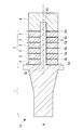
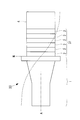
- FIG. 1 is a longitudinal sectional view showing an overall configuration of an ultrasonic transducer according to a first embodiment of the present invention.
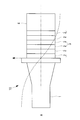
- FIG. 2 is a simplified diagram illustrating an overall configuration of the ultrasonic transducer of FIG. 1.
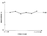
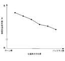
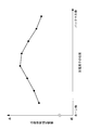
- 2 is a graph showing a distribution of mechanical loss coefficients in the laminate of the ultrasonic transducer of FIG. 1.
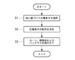
- 2 is a flowchart showing a method for manufacturing the ultrasonic transducer of FIG. 1.
- FIG. 6 is a simplified diagram illustrating an overall configuration of an ultrasonic transducer according to a second embodiment of the present invention. It is a graph which shows distribution of the mechanical loss coefficient in the laminated body of the ultrasonic transducer
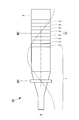
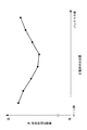
- FIG. 6 is a simplified diagram showing an overall configuration of an ultrasonic transducer according to a third embodiment of the present invention. It is a graph which shows distribution of the mechanical loss coefficient in the laminated body of the ultrasonic transducer
- the ultrasonic transducer 10 which concerns on the 1st Embodiment of this invention, and its manufacturing method are demonstrated with reference to FIGS.
- the ultrasonic transducer 10 is a bolted Langevin type (BLT) transducer, and in order along the longitudinal axis A from the distal end side toward the proximal end side, 1, a laminated body 3 in which a plurality of piezoelectric elements 2 are laminated, and a back mass 4.
- BLT Langevin type
- the horn 1 has a columnar shape extending along the longitudinal axis A, and has a shape in which the area of the cross section perpendicular to the longitudinal axis A decreases from the proximal end toward the distal end.
- the horn 1 is made of a metal having high strength such as a titanium alloy.
- a columnar bolt 5 extending along the longitudinal axis A is provided at a substantially central position of the base end face of the horn 1.
- the piezoelectric element 2 is a ring-shaped plate member made of a piezoelectric material such as PZT (lead titanium zirconate).
- the laminate 3 has a laminated structure in which the piezoelectric elements 2 and the electrodes 6a or 6b are alternately laminated in the longitudinal axis A direction so that each piezoelectric element 2 is sandwiched between the two electrodes 6a and 6b in the longitudinal axis A direction.
- the electrodes alternately constitute positive electrodes 6a and negative electrodes 6b in the longitudinal axis A direction, and each piezoelectric element 2 expands and contracts in the longitudinal axis A direction when alternating power is supplied to the electrodes 6a and 6b. It is like that.
- the laminated body 3 is electrically connected to the horn 1 and the back mass 4. Insulated. Further, the laminated body 3 is formed with a bolt hole 3a that penetrates from the front end to the base end along the longitudinal axis A and into which the bolt 5 is inserted.
- the back mass 4 is a columnar member formed from a metal material such as aluminum.
- a screw hole 4 a that is fastened to the bolt 5 is formed along the longitudinal axis A on the front end surface of the back mass 4.
- the bolt 3 is inserted into the bolt hole 3 a of the laminated body 3, and the back mass 4 is fastened to the base end portion of the bolt 5 protruding from the base end surface of the laminated body 3. And are tightened firmly from both sides.
- the ultrasonic transducer 10 is a half wavelength resonance type. That is, the dimension in the longitudinal axis A direction of the ultrasonic transducer 10 is designed to be half the wavelength of the resonance frequency of the ultrasonic transducer 10. Thereby, as shown in FIG. 2, the ultrasonic transducer 10 resonates at half wavelength when alternating power having a resonance frequency is supplied to the electrodes 6 a and 6 b. In half-wave resonance, two antinodes appear at the tip of the horn 1 and the base end of the back mass, and one node N appears at the boundary between the horn 1 and the laminate 2.
- vibrator 10 may not be a half wavelength resonance type but the 1 wavelength resonance type which has the dimension of the longitudinal axis A direction same as the wavelength of resonance frequency.
- each piezoelectric element 2 has the same or similar mechanical quality factor Qm (hereinafter simply referred to as “Qm”). Specifically, the Qm of each piezoelectric element 2 is within an average value M (Qm) ⁇ 2.5% of the Qm of all the piezoelectric elements 2. Therefore, the difference in Qm between two piezoelectric elements 2 adjacent in the longitudinal axis A direction is 5% of the average value M (Qm) at the maximum.
- each data point corresponds to each piezoelectric element 2.
- the manufacturing method of the ultrasonic transducer 10 includes the piezoelectric element selection step S1 for selecting the piezoelectric element 2 based on Qm, and the arrangement of the piezoelectric elements 2 in the laminate 3.
- An arrangement determining step S2 to be determined and an assembling step S3 for assembling the laminate 3, the horn 1 and the back mass 4 into one are included.
- the Qm of the piezoelectric element 2 purchased from the manufacturer varies by several hundreds.
- As many piezoelectric elements 2 having the same or approximate Qm as the number required for the stacked body 3 (six in this example) are selected. Specifically, the six piezoelectric elements 2 have a variation in Qm of 6 pieces so that the Qm average value M (Qm) of the six piezoelectric elements 2 is within ⁇ 2.5%. The piezoelectric element 2 is selected.
- the array of the six piezoelectric elements 2 selected in the piezoelectric element selection step S1 is randomly determined.
- the six piezoelectric elements 2 and the electrodes 6a and 6b are alternately stacked so that the six piezoelectric elements 2 are arranged according to the random arrangement determined in the arrangement determination step S2.
- the laminated body 3 is formed.
- the bolt 5 of the horn 1 is inserted into the bolt hole 3 a of the formed laminate 3, the back mass 4 is fastened to the tip of the bolt 5 protruding from the laminate 3, and the laminate 3 is attached to the longitudinal axis A. Compress in the direction. Thereby, the ultrasonic transducer
- an alternating power having a resonance frequency of the ultrasonic vibrator 10 or a frequency near the resonance frequency is electrically supplied from a power source (not shown). It supplies to electrodes 6a and 6b via a cable (not shown). Thereby, each piezoelectric element 2 expands and contracts in the longitudinal axis A direction, and the laminate 3 generates longitudinal vibration. Longitudinal vibration generated in the laminate 3 is transmitted to the horn 1, and the tip of the horn 1 vibrates at high frequency in the direction of the longitudinal axis A.
- the mechanical quality factor Qm is a coefficient representing the elastic loss that occurs in the piezoelectric element 2 during stretching vibration, and is the reciprocal of the mechanical loss coefficient.
- the laminated body 3 Since the inside of the same piezoelectric element is homogeneous, the transmission efficiency of vibration in the same piezoelectric element is high, and the vibration is transmitted without being attenuated. Therefore, if the laminated body 3 is composed of a single homogeneous piezoelectric element, the entire laminated body 3 vibrates longitudinally in synchronism and heat generation in the laminated body 3 is small.
- the actual laminated body 3 has a laminated structure of a plurality of piezoelectric elements 2, and the properties of the piezoelectric elements 2 change discontinuously between the piezoelectric elements 2 and the other piezoelectric elements 2. In this way, at the boundary between the piezoelectric elements 2 whose properties change discontinuously, a part of the longitudinal vibration is lost due to reflection or the like, so that vibration from the piezoelectric element 2 to another adjacent piezoelectric element 2 occurs. The transmission efficiency decreases. Also, heat is generated with the loss of vibration. That is, the vibration reflected at the boundary of the piezoelectric element 2 acts with other vibrations to generate harmonics that cause heat generation.
- the ultrasonic transducer 10 since the piezoelectric element 2 having substantially the same Qm is used for the laminated body 3, the Qm in the laminated body 3 is substantially uniform. Therefore, the multilayer body 3 composed of a plurality of piezoelectric elements 2 behaves similarly to the multilayer body composed of a single piezoelectric element. In the multilayer body 3, longitudinal vibration is transmitted with high efficiency without being attenuated, and the multilayer body 3 Heat generation at is suppressed. Thereby, even if the alternating power supplied to the electrodes 6a and 6b is increased in order to increase the output of the ultrasonic transducer 10 (the amplitude of the tip of the horn 1), the ultrasonic transducer 10 does not rise in temperature. There is an advantage that a high output can be continuously exhibited.
- the laminate 3 has the largest amount of heat generation. Therefore, by suppressing the heat generation in the laminated body 3, there is an advantage that the temperature rise of the entire ultrasonic transducer 10 can be efficiently suppressed. In addition, there is an advantage that the ultrasonic transducer 10 with a small amount of heat generation can be manufactured only by changing the selection of the piezoelectric element 2 from the conventional BLT transducer manufacturing method.
- vibrator 20 which concerns on the 2nd Embodiment of this invention, and its manufacturing method are demonstrated with reference to FIG. 5 and FIG.
- the ultrasonic transducer 20 according to the present embodiment is different from the ultrasonic transducer 10 of the first embodiment in the arrangement of the piezoelectric elements 2 in the multilayer body 31. Therefore, in this embodiment, the laminated body 31 is mainly demonstrated, the same code
- the ultrasonic transducer 20 is a half-wavelength resonance type like the ultrasonic transducer 10.
- the piezoelectric elements 2 are arranged such that Qm decreases in order from the horn 1 side toward the back mass 4 side, as shown in FIG. Accordingly, the Qm of the piezoelectric element 2 located closest to the horn 1 is the largest, and the Qm of the piezoelectric element 2 located closest to the back mass 4 is the smallest. Furthermore, the difference in Qm between the piezoelectric elements 2 adjacent in the longitudinal axis A direction is within 5% of the average value M (Qm) of Qm of the six piezoelectric elements 2.
- the method for manufacturing the ultrasonic transducer 20 includes a piezoelectric element selection step, an arrangement determination step, and an assembly step.
- the piezoelectric element selection step the Qm of the piezoelectric element 2 is measured in the same manner as the piezoelectric element selection step S1 described in the first embodiment.
- the variation in Qm of the six piezoelectric elements 2 is within ⁇ 15% with respect to the average value M (Qm) of the six piezoelectric elements 2, and the Qm values are in order of magnitude.
- the six piezoelectric elements 2 are selected so that the difference between adjacent Qm when arranged is within 5% of the average value M (Qm).
- the arrangement of the six piezoelectric elements 2 selected in the selection step is sequentially performed from the piezoelectric element 2 positioned closest to the horn 1 toward the piezoelectric element 2 positioned closest to the back mass 4. Is determined so that Qm becomes smaller.
- the six piezoelectric elements 2 and the electrodes 6a and 6b are alternately stacked so that the six piezoelectric elements 2 are arranged according to the arrangement determined in the arrangement determination step.
- the horn 1, the laminate 3 and the back mass 4 are arranged so that the piezoelectric element 2 having the largest Qm is arranged on the horn 1 side and the piezoelectric element 2 having the smallest Qm is arranged on the back mass 4 side. Are assembled into one.
- the ultrasonic transducer 20 has the following effects in addition to the effects of the first embodiment. As described above, there is an individual error in the Qm of the piezoelectric element 2, and there is a variation in the Qm of the piezoelectric element 2 purchased from the manufacturer. When only the piezoelectric elements 2 having substantially the same Qm are selected and used as in the first embodiment, some of the purchased piezoelectric elements 2 cannot be used for manufacturing. According to this embodiment, there is an advantage that the purchased piezoelectric element 2 can be effectively used for manufacturing by using the piezoelectric elements 2 having different Qm in combination.
- the piezoelectric element 2 having a large Qm on the side close to the horn 1, the longitudinal vibration generated in the laminate 3 is efficiently transmitted to the horn 1.
- the input / output efficiency of the ultrasonic transducer 20 (vibration amplitude of the horn 1 with respect to the alternating power supplied to the electrodes 6a and 6b) is increased, and a large output is obtained while reducing the alternating power supplied to the electrodes 6a and 6b.
- the horn 1 has a larger Qm than the piezoelectric element 2, and vibration loss and heat generation due to the difference in Qm occur at the boundary between the horn 1 and the piezoelectric element 2. Therefore, by disposing the piezoelectric element 2 having the largest Qm next to the horn 1 and minimizing the difference between the Qm of the horn 1 and the Qm of the piezoelectric element 2, vibration transmission from the laminate 3 to the horn 1 is achieved. There is an advantage that efficiency can be increased and heat generation can be further suppressed.
- the ultrasonic transducer 30 according to the present embodiment is different from the ultrasonic transducer 10 of the first embodiment in the arrangement of the piezoelectric elements 2 in the multilayer body 32. Therefore, in this embodiment, the laminated body 32 is mainly demonstrated, the same code
- the ultrasonic transducer 30 differs from the ultrasonic transducers 10 and 20 according to the first and second embodiments and is a one-wavelength resonance type. That is, the dimension in the longitudinal axis A direction of the ultrasonic transducer 30 is designed to be the same as the wavelength of the resonance frequency of the ultrasonic transducer 30. Thereby, as shown in FIG. 7, the ultrasonic transducer 30 resonates one wavelength when the alternating power having the resonance frequency is supplied to the electrodes 6a and 6b. In one-wavelength resonance, three antinodes appear, and two nodes N1 and N2 appear at a midway position in the longitudinal direction of the horn 1 and at a midway position in the longitudinal direction of the laminate 3.
- the laminated body 32 includes eight piezoelectric elements 2.
- the piezoelectric element 2 has a Qm that decreases in order from the piezoelectric element 2 located closest to the horn 1 toward the piezoelectric element 2 located at the node N2. They are arranged so that Qm increases in order from the piezoelectric element 2 positioned at N2 toward the piezoelectric element 2 positioned closest to the back mass 4. At this time, it is preferable that the piezoelectric element 2 having the largest Qm is located closest to the horn 1. Further, the difference in Qm between the piezoelectric elements 2 adjacent in the longitudinal axis A direction is within 5% of the average value M (Qm) of the Qm of the eight piezoelectric elements 2.
- the method for manufacturing the ultrasonic transducer 30 includes a piezoelectric element selection step, an arrangement determination step, and an assembly step.
- the piezoelectric element selection step the Qm of the piezoelectric element 2 is measured in the same manner as the piezoelectric element selection step S1 described in the first embodiment.
- the variation of Qm of the eight piezoelectric elements 2 is within ⁇ 7.5% with respect to the average value M (Qm) of the Qm of the eight piezoelectric elements 2, and each piezoelectric element
- the eight piezoelectric elements 2 are selected so that the difference between the Qm of 2 and the Qm of at least one other piezoelectric element 2 is within 5% of the average value M (Qm).
- the arrangement of the eight piezoelectric elements 2 selected in the selection step is such that Qm is minimized at the node N2, and Qm is sequentially turned from the node N2 toward the horn 1 side and the back mass 4 side. Decide to be larger.
- the eight piezoelectric elements 2 and the electrodes 6a and 6b are alternately stacked so that the eight piezoelectric elements 2 are arranged according to the arrangement determined in the arrangement determination step. Form.
- the formed laminate 3, horn 1, and back mass 4 are assembled into one.
- the ultrasonic transducer 30 has the following effects in addition to the effects of the first embodiment.
- similarly to the second embodiment by using a combination of piezoelectric elements 2 having different Qm, there is an advantage that the purchased piezoelectric element 2 can be effectively used for manufacturing. is there.
- the piezoelectric element 2 having a large Qm on the side close to the horn 1, the input / output efficiency of the ultrasonic transducer 30 (vibration amplitude of the horn 1 with respect to the alternating power supplied to the electrodes 6a and 6b) is increased. There is an advantage that a large output can be obtained while reducing the alternating power supplied to the electrodes 6a and 6b. Furthermore, the piezoelectric element 2 having the smallest position Qm is arranged at the node N2 where the amplitude of the longitudinal vibration is zero in the multilayer body 3, and the piezoelectric element 2 having a larger Qm is arranged at a position where the amplitude becomes larger. Thus, there is an advantage that the transmission efficiency of the longitudinal vibration can be improved and the heat generation in the stacked body 3 can be further reduced.
- the ultrasonic transducer 40 is a one-wavelength resonance type like the ultrasonic transducer 30, and the stacked body 33 includes eight piezoelectric elements 2. .
- the piezoelectric element 2 has a Qm that increases in order from the piezoelectric element 2 located closest to the horn 1 toward the piezoelectric element 2 located at the node N2, and The piezoelectric elements 2 are arranged so that the Qm decreases in order from the piezoelectric element 2 located at 2 toward the piezoelectric element 2 located closest to the back mass 4. Further, the difference in Qm between the piezoelectric elements 2 adjacent in the longitudinal axis A direction is within 5% of the average value M (Qm) of the Qm of the eight piezoelectric elements 2.
- the method for manufacturing the ultrasonic transducer 40 includes a piezoelectric element selection step, an arrangement determination step, and an assembly step.
- the piezoelectric element selection step of the present embodiment is the same as the piezoelectric element selection step described in the third embodiment.
- the arrangement of the eight piezoelectric elements 2 selected in the selection step is such that Qm is maximized at the node N2, and Qm is sequentially turned from the node N2 toward the horn 1 side and the back mass 4 side. Decide to be smaller.
- the eight piezoelectric elements 2 and the electrodes 6a and 6b are alternately stacked so that the eight piezoelectric elements 2 are arranged according to the arrangement determined in the arrangement determination step. Form.
- the formed laminate 3, horn 1, and back mass 4 are assembled into one.
- the ultrasonic transducer 40 according to this embodiment has the following effects in addition to the effects of the first embodiment. According to this embodiment, similarly to the second embodiment, by using a combination of piezoelectric elements 2 having different Qm, there is an advantage that the purchased piezoelectric element 2 can be effectively used for manufacturing. is there.
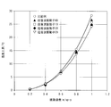
- FIG. 11 shows the temperature when the ultrasonic vibrators 10, 20, 30, 40 according to the first to fourth embodiments are supplied with alternating power of equal power amount to cause half-wave resonance or single-wave resonance. It is a graph which shows the result of having measured the rise. As a comparative example, the temperature rise of an ultrasonic transducer manufactured using a randomly selected piezoelectric element was also measured.
- the amount of temperature increase of the ultrasonic transducers 10, 20, 30, and 40 according to the present embodiment is significantly smaller than that of the comparative example.
- heat generation of the ultrasonic transducers 20 and 30 can be effectively suppressed by disposing the piezoelectric element 2 having a small Qm and a large Qm on the horn 1 side with a small amount of temperature rise.
- the temperature rise amount of the ultrasonic transducer 20 is 4 ° C. lower than that of the comparative example, and even if the alternating power supplied to the ultrasonic transducer 20 is increased by 11 W (14%), the temperature rise is equivalent to that of the comparative example. It was confirmed that it can be suppressed.
Landscapes
- Engineering & Computer Science (AREA)
- Mechanical Engineering (AREA)
- Physics & Mathematics (AREA)
- Acoustics & Sound (AREA)
- Signal Processing (AREA)
- Transducers For Ultrasonic Waves (AREA)
- Apparatuses For Generation Of Mechanical Vibrations (AREA)
- Piezo-Electric Transducers For Audible Bands (AREA)
Abstract
本発明の超音波振動子の製造方法は、積層体における複数の圧電素子の配列を各圧電素子が有する機械的品質係数に基づいて決定する配列決定ステップ(S2)と、該配列決定ステップにおいて決定された配列に従って複数の圧電素子が配列された積層体、ホーン、およびバックマスを1つに組み立てる組立ステップ(S3)とを含み、配列決定ステップ(S2)において、長手方向に隣接する圧電素子間の機械的品質係数の差が、複数の圧電素子の機械的品質係数の平均値の5%以内となるように、複数の圧電素子の配列を決定する。
Description
本発明は、超音波振動子の製造方法および超音波振動子に関するものである。
従来、生体組織の切開等の処置において超音波治療装置が使用されている(例えば、特許文献1参照。)。また、治療用超音波装置に搭載される超音波振動子の1つとして、高出力のボルト締めランジュバン型(BLT)振動子が知られている(例えば、特許文献2参照。)。
超音波振動子は振動に伴って発熱し、超音波振動子を内蔵するハンドピースの温度が上昇する。そこで、ハンドピースの表面温度を操作者が素手で把持可能な温度に保つために、ハンドピースのグリップ部分に放熱フィンのような空冷構造を設けた超音波治療装置が提案されている(例えば、特許文献3参照)。
しかしながら、特許文献3の空冷構造による放熱量は不十分であり、超音波振動子の温度上昇を十分に抑制することは難しい。例えば、骨や軟骨等の硬組織や石灰化した組織の処置においては、非常に高い出力が必要とされ、超音波振動子への電力投入量を増大する必要がある。このような場合、超音波振動子による発熱量も非常に大きくなって発熱量が空冷構造による放熱量を上回り、超音波振動子の温度が上昇する。
超音波振動子の共振周波数は温度に依存するため、温度上昇によって超音波振動子の共振周波数が変化すると、超音波振動子に供給されている駆動電力の周波数に対する超音波振動子の共振周波数のずれが大きくなり、超音波振動子の出力(振動振幅)が低下する。高出力を維持し続けるためには電力投入量をさらに増大しなければならず、さらなる発熱を招いたり超音波振動子の駆動が不安定になったりする。このように、特許文献3においては、超音波振動子を高い出力で安定的に駆動し続けることが難しいという問題がある。
本発明は、上述した事情に鑑みてなされたものであって、振動に伴う温度上昇を抑制し、高い出力で安定的に駆動し続けることができる超音波振動子の製造方法および超音波振動子を提供することを目的とする。
上記目的を達成するため、本発明は以下の手段を提供する。
本発明の第1の態様は、先端側から基端側へ向かって長手方向に沿って順に、ホーンと、複数の圧電素子が前記長手方向に積層された積層体と、バックマスとを備え、前記長手方向の縦振動を発生する超音波振動子の製造方法であって、前記積層体における前記複数の圧電素子の配列を各前記圧電素子が有する機械的品質係数に基づいて決定する配列決定ステップと、該配列決定ステップにおいて決定された配列に従って前記複数の圧電素子が配列された前記積層体、前記ホーン、および前記バックマスを1つに組み立てる組立ステップとを含み、前記配列決定ステップにおいて、前記長手方向に隣接する圧電素子間の機械的品質係数の差が、前記複数の圧電素子の機械的品質係数の平均値の5%以内となるように、前記複数の圧電素子の配列を決定する超音波振動子の製造方法である。
本発明の第1の態様は、先端側から基端側へ向かって長手方向に沿って順に、ホーンと、複数の圧電素子が前記長手方向に積層された積層体と、バックマスとを備え、前記長手方向の縦振動を発生する超音波振動子の製造方法であって、前記積層体における前記複数の圧電素子の配列を各前記圧電素子が有する機械的品質係数に基づいて決定する配列決定ステップと、該配列決定ステップにおいて決定された配列に従って前記複数の圧電素子が配列された前記積層体、前記ホーン、および前記バックマスを1つに組み立てる組立ステップとを含み、前記配列決定ステップにおいて、前記長手方向に隣接する圧電素子間の機械的品質係数の差が、前記複数の圧電素子の機械的品質係数の平均値の5%以内となるように、前記複数の圧電素子の配列を決定する超音波振動子の製造方法である。
本発明の第1の態様によれば、組立ステップにおいて、圧電素子の積層構造を有する積層体がホーンとバックマスとによって両側から挟まれるように、積層体、ホーンおよびバックマスを1つに組み立てることによって、超音波振動子を製造することができる。
この場合に、隣接する圧電素子間の機械的品質係数の差は最大でも平均値の5%となるように、配列決定ステップにおいて圧電素子の配列が決定される。このように、同一または近似する機械的品質係数を有する圧電素子同士が隣接するように圧電素子を配列することによって、圧電素子間の振動の伝達効率が向上して振動の熱への変換が抑制され、超音波振動子の発熱が抑制される。これにより、振動に伴う超音波振動子の温度上昇を抑制し、高い出力で安定的に超音波振動子を駆動し続けることができる。
この場合に、隣接する圧電素子間の機械的品質係数の差は最大でも平均値の5%となるように、配列決定ステップにおいて圧電素子の配列が決定される。このように、同一または近似する機械的品質係数を有する圧電素子同士が隣接するように圧電素子を配列することによって、圧電素子間の振動の伝達効率が向上して振動の熱への変換が抑制され、超音波振動子の発熱が抑制される。これにより、振動に伴う超音波振動子の温度上昇を抑制し、高い出力で安定的に超音波振動子を駆動し続けることができる。
上記第1の態様においては、機械的品質係数に基づいて前記複数の圧電素子を選択する圧電素子選択ステップを含み、該圧電素子選択ステップにおいて、前記複数の圧電素子の機械的品質係数の平均値に対して前記複数の圧電素子の機械的品質係数のばらつきが±2.5%以内となるように、前記複数の圧電素子を選択し、前記配列決定ステップにおいて、前記圧電素子選択ステップにおいて選択された前記複数の圧電素子の配列を決定してもよい。
このようにすることで、隣接する圧電素子間の機械的品質係数の差は必ず5%以内となるので、配列決定ステップにおいては、圧電素子の配列をランダムに決定することができる。
このようにすることで、隣接する圧電素子間の機械的品質係数の差は必ず5%以内となるので、配列決定ステップにおいては、圧電素子の配列をランダムに決定することができる。
上記第1の態様においては、前記配列決定ステップにおいて、前記ホーン側から前記バックマス側に向かって順番に機械的品質係数が小さくなるように、前記複数の圧電素子の内、前記ホーン側の少なくとも一部の配列を決定してもよい。
このようにすることで、ホーンに近い側に大きな機械的品質係数を有する圧電素子が配置されるので、積層体において発生した縦振動がホーンに効率的に伝達される。これにより、入出力効率(供給電力量に対する縦振動の振幅)を向上し、超音波振動子の駆動に必要な電力を低減することができる。また、ホーンと該ホーンに隣接する圧電素子との間の機械的品質係数の差が小さくなるので、ホーンと圧電素子との境界における発熱を抑制し、超音波振動子の発熱をさらに抑制することができる。
このようにすることで、ホーンに近い側に大きな機械的品質係数を有する圧電素子が配置されるので、積層体において発生した縦振動がホーンに効率的に伝達される。これにより、入出力効率(供給電力量に対する縦振動の振幅)を向上し、超音波振動子の駆動に必要な電力を低減することができる。また、ホーンと該ホーンに隣接する圧電素子との間の機械的品質係数の差が小さくなるので、ホーンと圧電素子との境界における発熱を抑制し、超音波振動子の発熱をさらに抑制することができる。
上記第1の態様においては、前記超音波振動子が、半波長共振型であり、前記配列決定ステップにおいて、最も前記ホーン側に位置する前記圧電素子から最も前記バックマス側に位置する前記圧電素子に向かって順番に機械的品質係数が小さくなるように、前記複数の圧電素子の配列を決定してもよい。
このようにすることで、超音波振動子の発熱をさらに抑制することができるとともに、さらに高い入出力効率を得ることができる。
このようにすることで、超音波振動子の発熱をさらに抑制することができるとともに、さらに高い入出力効率を得ることができる。
上記第1の態様においては、前記超音波振動子が、1波長共振型であり、前記配列決定ステップにおいて、最も前記ホーン側に位置する前記圧電素子から前記縦振動の節に位置する前記圧電素子に向かって順番に機械的品質係数が小さくなり、かつ、前記縦振動の節に位置する前記圧電素子から最も前記バックマス側に位置する前記圧電素子に向かって順番に機械的品質係数が大きくなるように、前記複数の圧電素子の配列を決定してもよい。
このようにすることで、超音波振動子の発熱をさらに抑制することができるとともに、さらに高い入出力効率を得ることができる。
このようにすることで、超音波振動子の発熱をさらに抑制することができるとともに、さらに高い入出力効率を得ることができる。
上記第1の態様においては、前記超音波振動子が、1波長共振型であり、前記配列決定ステップにおいて、最も前記ホーン側に位置する前記圧電素子から前記縦振動の腹に位置する前記圧電素子に向かって順番に機械的品質係数が大きくなり、かつ、前記縦振動の腹に位置する前記圧電素子から最も前記バックマス側に位置する前記圧電素子に向かって順番に機械的品質係数が小さくなるように、前記複数の圧電素子の配列を決定してもよい。
このようにすることで、超音波振動子の発熱をより抑制することができる。
このようにすることで、超音波振動子の発熱をより抑制することができる。
本発明の第2の態様は、先端側から基端側へ向かって長手方向に沿って順に、ホーンと、複数の圧電素子が前記長手方向に積層された積層体と、バックマスとを備え、前記複数の圧電素子は、前記長手方向に隣接する圧電素子間の機械的品質係数の差が、前記複数の圧電素子の機械的品質係数の平均値の5%以内となるように配列されている超音波振動子である。
上記第2の態様においては、前記複数の圧電素子の機械的品質係数のばらつきが、前記複数の圧電素子の機械的品質係数の平均値に対して±2.5%以内であってもよい。
上記第2の態様においては、前記複数の圧電素子は、最も前記ホーン側に位置する前記圧電素子から前記長手方向の縦振動の腹に位置する前記圧電素子に向かって順番に機械的品質係数が小さくなるように、配列されていてもよい。
上記第2の態様においては、前記複数の圧電素子は、最も前記ホーン側に位置する前記圧電素子から前記長手方向の縦振動の腹に位置する前記圧電素子に向かって順番に機械的品質係数が小さくなるように、配列されていてもよい。
上記第2の態様においては、半波長共振型であり、前記複数の圧電素子は、最も前記ホーン側に位置する前記圧電素子から最も前記バックマス側に位置する前記圧電素子に向かって順番に機械的品質係数が小さくなるように、配列されていてもよい。
上記第2の態様においては、1波長共振型であり、前記複数の圧電素子は、最も前記ホーン側に位置する前記圧電素子から前記縦振動の腹に位置する前記圧電素子に向かって順番に機械的品質係数が小さくなり、かつ、前記縦振動の腹に位置する前記圧電素子から最も前記バックマス側に位置する前記圧電素子に向かって順番に機械的品質係数が大きくなるように、配列されていてもよい。
上記第2の態様においては、1波長共振型であり、前記複数の圧電素子は、最も前記ホーン側に位置する前記圧電素子から前記縦振動の腹に位置する前記圧電素子に向かって順番に機械的品質係数が小さくなり、かつ、前記縦振動の腹に位置する前記圧電素子から最も前記バックマス側に位置する前記圧電素子に向かって順番に機械的品質係数が大きくなるように、配列されていてもよい。
上記第2の態様においては、1波長共振型であり、前記複数の圧電素子は、最も前記ホーン側に位置する前記圧電素子から前記長手方向の縦振動の腹に位置する前記圧電素子に向かって順番に機械的品質係数が大きくなり、かつ、前記縦振動の腹に位置する前記圧電素子から最も前記バックマス側に位置する前記圧電素子に向かって順番に機械的品質係数が小さくなるように、配列されていてもよい。
本発明によれば、振動に伴う温度上昇を抑制し、超音波振動子を高い出力で安定的に駆動し続けることができるという効果を奏する。
(第1の実施形態)
本発明の第1の実施形態に係る超音波振動子10とその製造方法について図1から図4を参照して説明する。
本実施形態に係る超音波振動子10は、図1に示されるように、ボルト締めランジュバン型(BLT)振動子であり、先端側から基端側へ向かって長手軸Aに沿って順に、ホーン1と、複数の圧電素子2が積層された積層体3と、バックマス4とを備えている。
本発明の第1の実施形態に係る超音波振動子10とその製造方法について図1から図4を参照して説明する。
本実施形態に係る超音波振動子10は、図1に示されるように、ボルト締めランジュバン型(BLT)振動子であり、先端側から基端側へ向かって長手軸Aに沿って順に、ホーン1と、複数の圧電素子2が積層された積層体3と、バックマス4とを備えている。
ホーン1は、長手軸Aに沿って延びる柱状であり、長手軸Aに直交する横断面の面積が基端から先端に向かう程小さくなる形状を有している。ホーン1は、チタン合金のような高い強度を有する金属から形成されている。ホーン1の基端面の略中心位置には、長手軸Aに沿って延びる柱状のボルト5が設けられている。
圧電素子2は、PZT(チタンジルコン酸鉛)のような圧電材料からなるリング状の板状部材である。積層体3は、各圧電素子2が2つの電極6a,6bによって長手軸A方向に挟まれるように、圧電素子2と電極6aまたは6bとが長手軸A方向に交互に積層された積層構造を有している。電極は、長手軸A方向に交互に正電極6aと負電極6bとを構成しており、電極6a,6bに交番電力が供給されたときに各圧電素子2が長手軸A方向に伸縮振動するようになっている。積層体3とホーン1との間、および、積層体3とバックマス4との間には、図示しない絶縁体が挟まれており、積層体3は、ホーン1およびバックマス4と電気的に絶縁されている。また、積層体3には、先端から基端まで長手軸Aに沿って貫通形成され、ボルト5が挿入されるボルト穴3aが形成されている。
バックマス4は、アルミのような金属材料から形成された柱状の部材である。バックマス4の先端面には、ボルト5に締結されるねじ穴4aが長手軸Aに沿って形成されている。
積層体3のボルト穴3a内にボルト5を挿入し、積層体3の基端面から突出したボルト5の基端部にバックマス4を締結することによって、積層体3がホーン1とバックマス4とによって両側から強固に締め付けられている。
積層体3のボルト穴3a内にボルト5を挿入し、積層体3の基端面から突出したボルト5の基端部にバックマス4を締結することによって、積層体3がホーン1とバックマス4とによって両側から強固に締め付けられている。
超音波振動子10は、半波長共振型である。すなわち、超音波振動子10の長手軸A方向の寸法は、超音波振動子10の共振周波数の波長の半分に設計されている。これにより、超音波振動子10は、図2に示されるように、共振周波数の交番電力が電極6a,6bに供給されたときに、半波長共振する。半波長共振において、2つの腹がホーン1の先端およびバックマスの基端に現れ、1つの節Nがホーン1と積層体2との境界に現れる。
なお、超音波振動子10は、半波長共振型ではなく、共振周波数の波長と同一の長手軸A方向の寸法を有する1波長共振型であってもよい。
なお、超音波振動子10は、半波長共振型ではなく、共振周波数の波長と同一の長手軸A方向の寸法を有する1波長共振型であってもよい。
さらに、図3に示されるように、積層体3において、全ての圧電素子2が、互いに同一または近似する機械的品質係数Qm(以下、単に「Qm」という。)を有している。具体的には、各圧電素子2のQmは、全ての圧電素子2のQmの平均値M(Qm)±2.5%以内である。したがって、長手軸A方向に隣接する2つの圧電素子2間のQmの差は、最大で平均値M(Qm)の5%となる。図3において、各データ点は各圧電素子2に対応している。
次に、超音波振動子10の製造方法について説明する。
本実施形態に係る超音波振動子10の製造方法は、図4に示されるように、Qmに基づいて圧電素子2を選択する圧電素子選択ステップS1と、圧電素子2の積層体3における配列を決定する配列決定ステップS2と、積層体3、ホーン1およびバックマス4を1つに組み立てる組立ステップS3とを含む。
本実施形態に係る超音波振動子10の製造方法は、図4に示されるように、Qmに基づいて圧電素子2を選択する圧電素子選択ステップS1と、圧電素子2の積層体3における配列を決定する配列決定ステップS2と、積層体3、ホーン1およびバックマス4を1つに組み立てる組立ステップS3とを含む。
製造会社から購入する圧電素子2のQmには、数100程度のばらつきがある。圧電素子選択ステップS1においては、まず、圧電素子2のQmを測定する。Qmの測定には、公知の任意の方法が用いられる。例えば、インピーダンスアナライザや周波数計測器等によって共振周波数fsおよび該共振周波数を示すピーク波形の半値幅(f2-f1)を測定し、Qm=fs/(f2-f1)の関係式からQmを算出する。次に、同一または近似のQmを有する圧電素子2を、積層体3に必要な数(本例においては6個)だけ選択する。具体的には、6個の圧電素子2のQmのばらつきが、該6個の圧電素子2のQmの平均値M(Qm)に対して±2.5%以内となるように、6個の圧電素子2を選択する。
次に、配列決定ステップS2において、圧電素子選択ステップS1において選択された6個の圧電素子2の配列をランダムに決定する。
次に、組立ステップS3において、6個の圧電素子2が、配列決定ステップS2において決定されたランダム配列に従って配列するように、6個の圧電素子2と電極6a,6bとを交互に積層して積層体3を形成する。次に、形成された積層体3のボルト穴3a内にホーン1のボルト5を挿入し、積層体3から突出したボルト5の先端部にバックマス4を締結して積層体3を長手軸A方向に圧縮する。これにより、超音波振動子10が製造される。
次に、組立ステップS3において、6個の圧電素子2が、配列決定ステップS2において決定されたランダム配列に従って配列するように、6個の圧電素子2と電極6a,6bとを交互に積層して積層体3を形成する。次に、形成された積層体3のボルト穴3a内にホーン1のボルト5を挿入し、積層体3から突出したボルト5の先端部にバックマス4を締結して積層体3を長手軸A方向に圧縮する。これにより、超音波振動子10が製造される。
次に、このように構成された超音波振動子10の作用について説明する。
本実施形態に係る超音波振動子10によって超音波振動を発生させるためには、電源(図示略)から、超音波振動子10の共振周波数または該共振周波数の近傍の周波数を有する交番電力を電気ケーブル(図示略)を介して電極6a,6bに供給する。これにより、個々の圧電素子2が長手軸A方向に伸縮振動して積層体3が縦振動を発生する。積層体3において発生した縦振動は、ホーン1に伝達され、ホーン1の先端が長手軸A方向に高周波振動する。
本実施形態に係る超音波振動子10によって超音波振動を発生させるためには、電源(図示略)から、超音波振動子10の共振周波数または該共振周波数の近傍の周波数を有する交番電力を電気ケーブル(図示略)を介して電極6a,6bに供給する。これにより、個々の圧電素子2が長手軸A方向に伸縮振動して積層体3が縦振動を発生する。積層体3において発生した縦振動は、ホーン1に伝達され、ホーン1の先端が長手軸A方向に高周波振動する。
ここで、圧電素子2のQmと積層体3における振動伝達との関係について説明する。
機械的品質係数Qmは、伸縮振動の際に圧電素子2に生じる弾性損失を表す係数であり、機械的損失係数の逆数である。機械的品質係数Qmが高い程、弾性損失が小さく、振動を減衰させ難く、発熱が少ない。したがって、超音波振動子10用の圧電素子2としては、例えば1000以上の高いQmを有する圧電素子が使用される。
機械的品質係数Qmは、伸縮振動の際に圧電素子2に生じる弾性損失を表す係数であり、機械的損失係数の逆数である。機械的品質係数Qmが高い程、弾性損失が小さく、振動を減衰させ難く、発熱が少ない。したがって、超音波振動子10用の圧電素子2としては、例えば1000以上の高いQmを有する圧電素子が使用される。
同一の圧電素子内は均質であるため、同一の圧電素子内における振動の伝達効率は高く、振動はほとんど減衰することなく伝達する。したがって、仮に、積層体3が、単一の均質な圧電素子から構成されていた場合、積層体3全体が同調して縦振動し、積層体3における発熱は少ない。
実際の積層体3は、複数の圧電素子2の積層構造を有し、圧電素子2と他の圧電素子2との間で圧電素子2の性質が不連続に変化する。このように、性質が不連続に変化する圧電素子2同士の境界においては、縦振動の一部が反射される等して損失するため、圧電素子2から隣接する他の圧電素子2への振動の伝達効率は低下する。また、振動の損失に伴って熱が発生する。すなわち、圧電素子2の境界で反射された振動が他の振動と作用することによって発熱の原因となる高調波を発生させる。また、隣接する2つの圧電素子2のQmに差がある場合は、一方の圧電素子2の伸縮挙動と他方の圧電素子2の伸縮挙動とにずれが生じることによって2つの圧電素子2の境界において滑り運動が生じ、摩擦熱が生じる。
本実施形態に係る超音波振動子10によれば、略等しいQmを有する圧電素子2を積層体3に使用しているので、積層体3におけるQmが略均一になっている。したがって、複数の圧電素子2からなる積層体3は、単一の圧電素子からなる積層体と類似の挙動を示し、積層体3において縦振動は減衰することなく高い効率で伝達するとともに積層体3における発熱が抑制される。これにより、超音波振動子10の出力(ホーン1の先端の振幅)を増大するために電極6a,6bに供給する交番電力を増大したとしても、超音波振動子10は、温度上昇することなく高い出力を安定的に発揮し続けることができるという利点がある。
特に、超音波振動子10を構成する部品の内、発熱量が最も大きいものは積層体3である。したがって、積層体3における発熱を抑制することによって、超音波振動子10全体の温度上昇を効率的に抑制することができるという利点がある。また、従来のBLT振動子の製造方法から圧電素子2の選択のみを変更するだけで、発熱量の少ない超音波振動子10を製造することができるという利点がある。
(第2の実施形態)
本発明の第2の実施形態に係る超音波振動子20およびその製造方法について図5および図6を参照して説明する。
本実施形態に係る超音波振動子20は、積層体31における圧電素子2の配列において、第1の実施形態の超音波振動子10と異なっている。したがって、本実施形態においては、積層体31について主に説明し、第1の実施形態と共通する構成については同一の符号を付して説明を省略する。
本発明の第2の実施形態に係る超音波振動子20およびその製造方法について図5および図6を参照して説明する。
本実施形態に係る超音波振動子20は、積層体31における圧電素子2の配列において、第1の実施形態の超音波振動子10と異なっている。したがって、本実施形態においては、積層体31について主に説明し、第1の実施形態と共通する構成については同一の符号を付して説明を省略する。
本実施形態に係る超音波振動子20は、図5に示されるように、超音波振動子10と同様に、半波長共振型である。
積層体31において、圧電素子2は、図6に示されるように、Qmが、ホーン1側からバックマス4側に向かって順番に小さくなるように配列されている。したがって、最もホーン1側に位置する圧電素子2のQmが最も大きくなっており、最もバックマス4側に位置する圧電素子2のQmが最も小さくなっている。さらに、長手軸A方向に隣接する圧電素子2間のQmの差は、6個の圧電素子2のQmの平均値M(Qm)の5%以内である。
積層体31において、圧電素子2は、図6に示されるように、Qmが、ホーン1側からバックマス4側に向かって順番に小さくなるように配列されている。したがって、最もホーン1側に位置する圧電素子2のQmが最も大きくなっており、最もバックマス4側に位置する圧電素子2のQmが最も小さくなっている。さらに、長手軸A方向に隣接する圧電素子2間のQmの差は、6個の圧電素子2のQmの平均値M(Qm)の5%以内である。
次に、超音波振動子20の製造方法について説明する。
本実施形態に係る超音波振動子20の製造方法は、圧電素子選択ステップと、配列決定ステップと、組立ステップとを含む。
圧電素子選択ステップにおいて、第1の実施形態において説明した圧電素子選択ステップS1と同様にして、圧電素子2のQmを測定する。次に、6個の圧電素子2のQmのばらつきが、該6個の圧電素子2のQmの平均値M(Qm)に対して±15%以内となるように、かつ、Qmを大きさ順に並べたときに隣接するQm間の差が平均値M(Qm)の5%以内となるように、6個の圧電素子2を選択する。
本実施形態に係る超音波振動子20の製造方法は、圧電素子選択ステップと、配列決定ステップと、組立ステップとを含む。
圧電素子選択ステップにおいて、第1の実施形態において説明した圧電素子選択ステップS1と同様にして、圧電素子2のQmを測定する。次に、6個の圧電素子2のQmのばらつきが、該6個の圧電素子2のQmの平均値M(Qm)に対して±15%以内となるように、かつ、Qmを大きさ順に並べたときに隣接するQm間の差が平均値M(Qm)の5%以内となるように、6個の圧電素子2を選択する。
次に、配列決定ステップにおいて、選択ステップにおいて選択された6個の圧電素子2の配列を、最もホーン1側に位置する圧電素子2から最もバックマス4側に位置する圧電素子2に向かって順番にQmが小さくなるように、決定する。
次に、組立ステップにおいて、6個の圧電素子2が、配列決定ステップにおいて決定された配列に従って配列するように、6個の圧電素子2と電極6a,6bとを交互に積層して積層体3を形成する。次に、最も大きなQmを有する圧電素子2がホーン1側に配置され、最も小さなQmを有する圧電素子2がバックマス4側に配置されるように、ホーン1と積層体3とバックマス4とを1つに組み立てる。
次に、組立ステップにおいて、6個の圧電素子2が、配列決定ステップにおいて決定された配列に従って配列するように、6個の圧電素子2と電極6a,6bとを交互に積層して積層体3を形成する。次に、最も大きなQmを有する圧電素子2がホーン1側に配置され、最も小さなQmを有する圧電素子2がバックマス4側に配置されるように、ホーン1と積層体3とバックマス4とを1つに組み立てる。
本実施形態に係る超音波振動子20によれば、第1の実施形態の効果に加えて以下の効果を奏する。
上述したように、圧電素子2のQmには個体誤差が存在し、製造会社から購入した圧電素子2のQmにはばらつきが存在する。第1の実施形態のように、略等しいQmを有する圧電素子2のみを選別して使用する場合、購入した圧電素子2の内、一部を製造に利用することができない。本実施形態によれば、異なるQmを有する圧電素子2を組み合わせて使用することによって、購入した圧電素子2を有効的に製造に利用することができるという利点がある。
上述したように、圧電素子2のQmには個体誤差が存在し、製造会社から購入した圧電素子2のQmにはばらつきが存在する。第1の実施形態のように、略等しいQmを有する圧電素子2のみを選別して使用する場合、購入した圧電素子2の内、一部を製造に利用することができない。本実施形態によれば、異なるQmを有する圧電素子2を組み合わせて使用することによって、購入した圧電素子2を有効的に製造に利用することができるという利点がある。
また、ホーン1に近い側に大きなQmを有する圧電素子2を配置することによって、積層体3において発生した縦振動がホーン1へ効率的に伝達される。これにより、超音波振動子20の入出力効率(電極6a,6bに供給される交番電力に対するホーン1の振動振幅)を高め、電極6a,6bに供給する交番電力を低減しながら大きな出力を得ることができるという利点がある。
さらに、ホーン1は圧電素子2よりも大きなQmを有し、ホーン1と圧電素子2との境界においても、Qmの差に起因する振動の損失および発熱が生じる。そこで、最も大きなQmを有する圧電素子2をホーン1の隣に配置し、ホーン1のQmと圧電素子2のQmとの差を最小とすることによって、積層体3からホーン1への振動の伝達効率的を高め、発熱をさらに抑制することができるという利点がある。
(第3の実施形態)
本発明の第3の実施形態に係る超音波振動子30およびその製造方法について図7および図8を参照して説明する。
本実施形態に係る超音波振動子30は、積層体32における圧電素子2の配列において、第1の実施形態の超音波振動子10と異なっている。したがって、本実施形態においては、積層体32について主に説明し、第1の実施形態と共通する構成については同一の符号を付して説明を省略する。
本発明の第3の実施形態に係る超音波振動子30およびその製造方法について図7および図8を参照して説明する。
本実施形態に係る超音波振動子30は、積層体32における圧電素子2の配列において、第1の実施形態の超音波振動子10と異なっている。したがって、本実施形態においては、積層体32について主に説明し、第1の実施形態と共通する構成については同一の符号を付して説明を省略する。
本実施形態に係る超音波振動子30は、図7に示されるように、第1および第2の実施形態に係る超音波振動子10,20とは全長が異なり、1波長共振型である。すなわち、超音波振動子30の長手軸A方向の寸法は、超音波振動子30の共振周波数の波長と同一に設計されている。これにより、超音波振動子30は、図7に示されるように、共振周波数の交番電力が電極6a,6bに供給されたときに、1波長共振する。1波長共振において、3つの腹が現れ、2つの節N1,N2がホーン1の長手方向の途中位置と積層体3の長手方向の途中位置に現れる。
本実施形態例において、積層体32は8個の圧電素子2を備えている。積層体32において、圧電素子2は、図8に示されるように、最もホーン1側に位置する圧電素子2から節N2に位置する圧電素子2に向かって順番にQmが小さくなり、かつ、節N2に位置する圧電素子2から最もバックマス4側に位置する圧電素子2に向かって順番にQmが大きくなるように、配列されている。このときに、最も大きなQmを有する圧電素子2が最もホーン1側に位置することが好ましい。さらに、長手軸A方向に隣接する圧電素子2間のQmの差は、8個の圧電素子2のQmの平均値M(Qm)の5%以内である。
次に、超音波振動子30の製造方法について説明する。
本実施形態に係る超音波振動子30の製造方法は、圧電素子選択ステップと、配列決定ステップと、組立ステップとを含む。
圧電素子選択ステップにおいて、第1の実施形態において説明した圧電素子選択ステップS1と同様にして、圧電素子2のQmを測定する。次に、8個の圧電素子2のQmのばらつきが、該8個の圧電素子2のQmの平均値M(Qm)に対して±7.5%以内となるように、かつ、各圧電素子2のQmと他の少なくとも1つの圧電素子2のQmとの差が平均値M(Qm)の5%以内となるように、8個の圧電素子2を選択する。
本実施形態に係る超音波振動子30の製造方法は、圧電素子選択ステップと、配列決定ステップと、組立ステップとを含む。
圧電素子選択ステップにおいて、第1の実施形態において説明した圧電素子選択ステップS1と同様にして、圧電素子2のQmを測定する。次に、8個の圧電素子2のQmのばらつきが、該8個の圧電素子2のQmの平均値M(Qm)に対して±7.5%以内となるように、かつ、各圧電素子2のQmと他の少なくとも1つの圧電素子2のQmとの差が平均値M(Qm)の5%以内となるように、8個の圧電素子2を選択する。
次に、配列決定ステップにおいて、選択ステップにおいて選択された8個の圧電素子2の配列を、節N2においてQmが最小となり、節N2からホーン1側およびバックマス4側に向かってQmが順番に大きくなるように、決定する。
次に、組立ステップにおいて、8個の圧電素子2が、配列決定ステップにおいて決定された配列に従って配列するように、8個の圧電素子2と電極6a,6bとを交互に積層して積層体3を形成する。次に、形成された積層体3とホーン1とバックマス4とを1つに組み立てる。
次に、組立ステップにおいて、8個の圧電素子2が、配列決定ステップにおいて決定された配列に従って配列するように、8個の圧電素子2と電極6a,6bとを交互に積層して積層体3を形成する。次に、形成された積層体3とホーン1とバックマス4とを1つに組み立てる。
本実施形態に係る超音波振動子30によれば、第1の実施形態の効果に加えて以下の効果を奏する。
本実施形態によれば、第2の実施形態と同様に、異なるQmを有する圧電素子2を組み合わせて使用することによって、購入した圧電素子2を有効的に製造に利用することができるという利点がある。
本実施形態によれば、第2の実施形態と同様に、異なるQmを有する圧電素子2を組み合わせて使用することによって、購入した圧電素子2を有効的に製造に利用することができるという利点がある。
また、ホーン1に近い側に大きなQmを有する圧電素子2を配置することによって、超音波振動子30の入出力効率(電極6a,6bに供給される交番電力に対するホーン1の振動振幅)を高め、電極6a,6bに供給する交番電力を低減しながら大きな出力を得ることができるという利点がある。
さらに、積層体3の内、縦振動の振幅がゼロとなる節N2に、最も小さい位置Qmを有する圧電素子2を配置し、振幅が大きくなる位置程、大きなQmを有する圧電素子2を配置することによって、縦振動の伝達効率を向上し、積層体3における発熱をさらに低減することができるという利点がある。
さらに、積層体3の内、縦振動の振幅がゼロとなる節N2に、最も小さい位置Qmを有する圧電素子2を配置し、振幅が大きくなる位置程、大きなQmを有する圧電素子2を配置することによって、縦振動の伝達効率を向上し、積層体3における発熱をさらに低減することができるという利点がある。
(第4の実施形態)
本発明の第4の実施形態に係る超音波振動子40およびその製造方法について図9および図10を参照して説明する。
本実施形態に係る超音波振動子40は、積層体33における圧電素子2の配列において、第3の実施形態の超音波振動子30と異なっている。したがって、本実施形態においては、積層体33について主に説明し、第3の実施形態と共通する構成については同一の符号を付して説明を省略する。
本発明の第4の実施形態に係る超音波振動子40およびその製造方法について図9および図10を参照して説明する。
本実施形態に係る超音波振動子40は、積層体33における圧電素子2の配列において、第3の実施形態の超音波振動子30と異なっている。したがって、本実施形態においては、積層体33について主に説明し、第3の実施形態と共通する構成については同一の符号を付して説明を省略する。
本実施形態に係る超音波振動子40は、図9に示されるように、超音波振動子30と同様に、1波長共振型であり、積層体33は8個の圧電素子2を備えている。
積層体33において、圧電素子2は、図10に示されるように、最もホーン1側に位置する圧電素子2から節N2に位置する圧電素子2に向かって順番にQmが大きくなり、かつ、節2に位置する圧電素子2から最もバックマス4側に位置する圧電素子2に向かって順番にQmが小さくなるように、配列されている。さらに、長手軸A方向に隣接する圧電素子2間のQmの差は、8個の圧電素子2のQmの平均値M(Qm)の5%以内である。
積層体33において、圧電素子2は、図10に示されるように、最もホーン1側に位置する圧電素子2から節N2に位置する圧電素子2に向かって順番にQmが大きくなり、かつ、節2に位置する圧電素子2から最もバックマス4側に位置する圧電素子2に向かって順番にQmが小さくなるように、配列されている。さらに、長手軸A方向に隣接する圧電素子2間のQmの差は、8個の圧電素子2のQmの平均値M(Qm)の5%以内である。
次に、超音波振動子40の製造方法について説明する。
本実施形態に係る超音波振動子40の製造方法は、圧電素子選択ステップと、配列決定ステップと、組立ステップとを含む。
本実施形態の圧電素子選択ステップは、第3の実施形態において説明した圧電素子選択ステップと同一である。
本実施形態に係る超音波振動子40の製造方法は、圧電素子選択ステップと、配列決定ステップと、組立ステップとを含む。
本実施形態の圧電素子選択ステップは、第3の実施形態において説明した圧電素子選択ステップと同一である。
次に、配列決定ステップにおいて、選択ステップにおいて選択された8個の圧電素子2の配列を、節N2においてQmが最大となり、節N2からホーン1側およびバックマス4側に向かってQmが順番に小さくなるように、決定する。
次に、組立ステップにおいて、8個の圧電素子2が、配列決定ステップにおいて決定された配列に従って配列するように、8個の圧電素子2と電極6a,6bとを交互に積層して積層体3を形成する。次に、形成された積層体3とホーン1とバックマス4とを1つに組み立てる。
次に、組立ステップにおいて、8個の圧電素子2が、配列決定ステップにおいて決定された配列に従って配列するように、8個の圧電素子2と電極6a,6bとを交互に積層して積層体3を形成する。次に、形成された積層体3とホーン1とバックマス4とを1つに組み立てる。
本実施形態に係る超音波振動子40によれば、第1の実施形態の効果に加えて以下の効果を奏する。
本実施形態によれば、第2の実施形態と同様に、異なるQmを有する圧電素子2を組み合わせて使用することによって、購入した圧電素子2を有効的に製造に利用することができるという利点がある。
本実施形態によれば、第2の実施形態と同様に、異なるQmを有する圧電素子2を組み合わせて使用することによって、購入した圧電素子2を有効的に製造に利用することができるという利点がある。
次に、上述した積層体3,31,32,33におけるQmの分布と、超音波振動子10,20,30,40発熱量との関係について説明する。
図11には、第1から第4の実施形態に係る超音波振動子10,20,30,40に、等しい電力量の交番電力を供給して半波長共振または1波長共振させたときの温度上昇を測定した結果を示すグラフである。比較例として、無作為に選択した圧電素子を使用して製造した超音波振動子の温度上昇も測定した。
図11には、第1から第4の実施形態に係る超音波振動子10,20,30,40に、等しい電力量の交番電力を供給して半波長共振または1波長共振させたときの温度上昇を測定した結果を示すグラフである。比較例として、無作為に選択した圧電素子を使用して製造した超音波振動子の温度上昇も測定した。
図11示されるように、本実施形態に係る超音波振動子10,20,30,40の温度上昇量は、比較例に比べて優位に小さいことが確認された。特に、超音波振動子20,30の温度上昇量が小さく、大きなQmを有する圧電素子2をホーン1側に配置することによって超音波振動子20,30の発熱を効果的に抑制できることが確認された。また、超音波振動子20の温度上昇量は、比較例に比べて4℃低く、超音波振動子20に供給する交番電力を11W(14%)増加したとしても、温度上昇を比較例と同等に抑制することができることが確認された。
10,20,30,40 超音波振動子
1 ホーン
2 圧電素子
3,31,32,33 積層体
4 バックマス
5 ボルト
6a,6b 電極
S1 圧電素子選択ステップ
S2 配列決定ステップ
S3 組立ステップ
1 ホーン
2 圧電素子
3,31,32,33 積層体
4 バックマス
5 ボルト
6a,6b 電極
S1 圧電素子選択ステップ
S2 配列決定ステップ
S3 組立ステップ
Claims (12)
- 先端側から基端側へ向かって長手方向に沿って順に、ホーンと、複数の圧電素子が前記長手方向に積層された積層体と、バックマスとを備え、前記長手方向の縦振動を発生する超音波振動子の製造方法であって、
前記積層体における前記複数の圧電素子の配列を各前記圧電素子が有する機械的品質係数に基づいて決定する配列決定ステップと、
該配列決定ステップにおいて決定された配列に従って前記複数の圧電素子が配列された前記積層体、前記ホーン、および前記バックマスを1つに組み立てる組立ステップとを含み、
前記配列決定ステップにおいて、前記長手方向に隣接する圧電素子間の機械的品質係数の差が、前記複数の圧電素子の機械的品質係数の平均値の5%以内となるように、前記複数の圧電素子の配列を決定する超音波振動子の製造方法。 - 機械的品質係数に基づいて前記複数の圧電素子を選択する圧電素子選択ステップを含み、
該圧電素子選択ステップにおいて、前記複数の圧電素子の機械的品質係数の平均値に対して前記複数の圧電素子の機械的品質係数のばらつきが±2.5%以内となるように、前記複数の圧電素子を選択し、
前記配列決定ステップにおいて、前記圧電素子選択ステップにおいて選択された前記複数の圧電素子の配列を決定する請求項1に記載の超音波振動子の製造方法。 - 前記配列決定ステップにおいて、前記ホーン側から前記バックマス側に向かって順番に機械的品質係数が小さくなるように、前記複数の圧電素子の内、前記ホーン側の少なくとも一部の配列を決定する請求項1に記載の超音波振動子の製造方法。
- 前記超音波振動子が、半波長共振型であり、
前記配列決定ステップにおいて、最も前記ホーン側に位置する前記圧電素子から最も前記バックマス側に位置する前記圧電素子に向かって順番に機械的品質係数が小さくなるように、前記複数の圧電素子の配列を決定する請求項3に記載の超音波振動子の製造方法。 - 前記超音波振動子が、1波長共振型であり、
前記配列決定ステップにおいて、最も前記ホーン側に位置する前記圧電素子から前記縦振動の節に位置する前記圧電素子に向かって順番に機械的品質係数が小さくなり、かつ、前記縦振動の節に位置する前記圧電素子から最も前記バックマス側に位置する前記圧電素子に向かって順番に機械的品質係数が大きくなるように、前記複数の圧電素子の配列を決定する請求項3に記載の超音波振動子の製造方法。 - 前記超音波振動子が、1波長共振型であり、
前記配列決定ステップにおいて、最も前記ホーン側に位置する前記圧電素子から前記縦振動の節に位置する前記圧電素子に向かって順番に機械的品質係数が大きくなり、かつ、前記縦振動の節に位置する前記圧電素子から最も前記バックマス側に位置する前記圧電素子に向かって順番に機械的品質係数が小さくなるように、前記複数の圧電素子の配列を決定する請求項1に記載の超音波振動子の製造方法。 - 先端側から基端側へ向かって長手方向に沿って順に、ホーンと、複数の圧電素子が前記長手方向に積層された積層体と、バックマスとを備え、
前記複数の圧電素子は、前記長手方向に隣接する圧電素子間の機械的品質係数の差が、前記複数の圧電素子の機械的品質係数の平均値の5%以内となるように配列されている超音波振動子。 - 前記複数の圧電素子の機械的品質係数のばらつきが、前記複数の圧電素子の機械的品質係数の平均値に対して±2.5%以内である請求項7に記載の超音波振動子。
- 前記複数の圧電素子は、最も前記ホーン側に位置する前記圧電素子から前記長手方向の縦振動の節に位置する前記圧電素子に向かって順番に機械的品質係数が小さくなるように、配列されている請求項7に記載の超音波振動子。
- 半波長共振型であり、
前記複数の圧電素子は、最も前記ホーン側に位置する前記圧電素子から最も前記バックマス側に位置する前記圧電素子に向かって順番に機械的品質係数が小さくなるように、配列されている請求項9に記載の超音波振動子。 - 1波長共振型であり、
前記複数の圧電素子は、最も前記ホーン側に位置する前記圧電素子から前記縦振動の節に位置する前記圧電素子に向かって順番に機械的品質係数が小さくなり、かつ、前記縦振動の節に位置する前記圧電素子から最も前記バックマス側に位置する前記圧電素子に向かって順番に機械的品質係数が大きくなるように、配列されている請求項9に記載の超音波振動子。 - 1波長共振型であり、
前記複数の圧電素子は、最も前記ホーン側に位置する前記圧電素子から前記長手方向の縦振動の節に位置する前記圧電素子に向かって順番に機械的品質係数が大きくなり、かつ、前記縦振動の節に位置する前記圧電素子から最も前記バックマス側に位置する前記圧電素子に向かって順番に機械的品質係数が小さくなるように、配列されている請求項7に記載の超音波振動子。
Priority Applications (5)
| Application Number | Priority Date | Filing Date | Title |
|---|---|---|---|
| PCT/JP2015/062683 WO2016174709A1 (ja) | 2015-04-27 | 2015-04-27 | 超音波振動子の製造方法および超音波振動子 |
| EP15890693.3A EP3291579A4 (en) | 2015-04-27 | 2015-04-27 | PROCESS FOR PRODUCING ULTRASONIC TRANSDUCER AND ULTRASONIC TRANSDUCER |
| JP2016526958A JP6091712B1 (ja) | 2015-04-27 | 2015-04-27 | 超音波振動子の製造方法および超音波振動子 |
| CN201580059183.7A CN107113513B (zh) | 2015-04-27 | 2015-04-27 | 超声波振子的制造方法和超声波振子 |
| US15/618,260 US20170274420A1 (en) | 2015-04-27 | 2017-06-09 | Method for producing ultrasonic transducer and ultrasonic transducer |
Applications Claiming Priority (1)
| Application Number | Priority Date | Filing Date | Title |
|---|---|---|---|
| PCT/JP2015/062683 WO2016174709A1 (ja) | 2015-04-27 | 2015-04-27 | 超音波振動子の製造方法および超音波振動子 |
Related Child Applications (1)
| Application Number | Title | Priority Date | Filing Date |
|---|---|---|---|
| US15/618,260 Continuation US20170274420A1 (en) | 2015-04-27 | 2017-06-09 | Method for producing ultrasonic transducer and ultrasonic transducer |
Publications (1)
| Publication Number | Publication Date |
|---|---|
| WO2016174709A1 true WO2016174709A1 (ja) | 2016-11-03 |
Family
ID=57199027
Family Applications (1)
| Application Number | Title | Priority Date | Filing Date |
|---|---|---|---|
| PCT/JP2015/062683 WO2016174709A1 (ja) | 2015-04-27 | 2015-04-27 | 超音波振動子の製造方法および超音波振動子 |
Country Status (5)
| Country | Link |
|---|---|
| US (1) | US20170274420A1 (ja) |
| EP (1) | EP3291579A4 (ja) |
| JP (1) | JP6091712B1 (ja) |
| CN (1) | CN107113513B (ja) |
| WO (1) | WO2016174709A1 (ja) |
Cited By (2)
| Publication number | Priority date | Publication date | Assignee | Title |
|---|---|---|---|---|
| CN110662146A (zh) * | 2019-10-14 | 2020-01-07 | 陕西师范大学 | 提高声换能器电压发射响应性能的方法及声换能器 |
| WO2023162861A1 (ja) * | 2022-02-22 | 2023-08-31 | 学校法人日本大学 | 超音波投射装置 |
Families Citing this family (6)
| Publication number | Priority date | Publication date | Assignee | Title |
|---|---|---|---|---|
| CN112604929A (zh) * | 2015-10-15 | 2021-04-06 | 优威富有限公司 | 朗之万型超声波振子的振动激励方法以及超声波加工方法和超声波发送方法 |
| CN109792580B (zh) * | 2016-09-30 | 2020-11-10 | 奥林巴斯株式会社 | 超声波转换器及超声波转换器的制造方法 |
| JP6745347B2 (ja) * | 2016-10-14 | 2020-08-26 | オリンパス株式会社 | 超音波トランスデューサ及び超音波処置システム |
| CN111504586B (zh) * | 2020-05-13 | 2021-12-24 | 吴疆 | 一种振动体机械品质因数的测量系统和测量方法 |
| DE102021108462A1 (de) | 2021-04-01 | 2022-10-06 | Herrmann Ultraschalltechnik Gmbh & Co. Kg | Konverter mit integriertem Bolzen |
| DE102021126665A1 (de) | 2021-10-14 | 2023-04-20 | Herrmann Ultraschalltechnik Gmbh & Co. Kg | Ultraschallschwingsystem mit mechanischem Resonator |
Citations (3)
| Publication number | Priority date | Publication date | Assignee | Title |
|---|---|---|---|---|
| JPH08213664A (ja) * | 1995-01-31 | 1996-08-20 | Nippon Cement Co Ltd | 積層セラミックス圧電体素子 |
| JP2003070271A (ja) * | 2001-08-23 | 2003-03-07 | Asmo Co Ltd | 振動駆動装置 |
| JP2003333695A (ja) * | 2002-05-15 | 2003-11-21 | Olympus Optical Co Ltd | ボルト締めランジュバン型振動子 |
Family Cites Families (4)
| Publication number | Priority date | Publication date | Assignee | Title |
|---|---|---|---|---|
| JP4624659B2 (ja) * | 2003-09-30 | 2011-02-02 | パナソニック株式会社 | 超音波探触子 |
| US20100106173A1 (en) * | 2008-10-23 | 2010-04-29 | Hideto Yoshimine | Ultrasonic surgical device |
| US8650728B2 (en) * | 2009-06-24 | 2014-02-18 | Ethicon Endo-Surgery, Inc. | Method of assembling a transducer for a surgical instrument |
| JP5301585B2 (ja) * | 2011-02-23 | 2013-09-25 | 富士フイルム株式会社 | 超音波処置具 |
-
2015
- 2015-04-27 CN CN201580059183.7A patent/CN107113513B/zh active Active
- 2015-04-27 WO PCT/JP2015/062683 patent/WO2016174709A1/ja unknown
- 2015-04-27 EP EP15890693.3A patent/EP3291579A4/en not_active Withdrawn
- 2015-04-27 JP JP2016526958A patent/JP6091712B1/ja active Active
-
2017
- 2017-06-09 US US15/618,260 patent/US20170274420A1/en not_active Abandoned
Patent Citations (3)
| Publication number | Priority date | Publication date | Assignee | Title |
|---|---|---|---|---|
| JPH08213664A (ja) * | 1995-01-31 | 1996-08-20 | Nippon Cement Co Ltd | 積層セラミックス圧電体素子 |
| JP2003070271A (ja) * | 2001-08-23 | 2003-03-07 | Asmo Co Ltd | 振動駆動装置 |
| JP2003333695A (ja) * | 2002-05-15 | 2003-11-21 | Olympus Optical Co Ltd | ボルト締めランジュバン型振動子 |
Non-Patent Citations (1)
| Title |
|---|
| See also references of EP3291579A4 * |
Cited By (2)
| Publication number | Priority date | Publication date | Assignee | Title |
|---|---|---|---|---|
| CN110662146A (zh) * | 2019-10-14 | 2020-01-07 | 陕西师范大学 | 提高声换能器电压发射响应性能的方法及声换能器 |
| WO2023162861A1 (ja) * | 2022-02-22 | 2023-08-31 | 学校法人日本大学 | 超音波投射装置 |
Also Published As
| Publication number | Publication date |
|---|---|
| US20170274420A1 (en) | 2017-09-28 |
| CN107113513B (zh) | 2019-11-08 |
| JPWO2016174709A1 (ja) | 2017-05-18 |
| EP3291579A1 (en) | 2018-03-07 |
| EP3291579A4 (en) | 2019-04-24 |
| JP6091712B1 (ja) | 2017-03-08 |
| CN107113513A (zh) | 2017-08-29 |
Similar Documents
| Publication | Publication Date | Title |
|---|---|---|
| JP6091712B1 (ja) | 超音波振動子の製造方法および超音波振動子 | |
| EP3838191B1 (en) | Ultrasonic transducer | |
| JP7234321B2 (ja) | 超音波トランスデューサの導波管への音響連結、接続、及び構成 | |
| JP4545323B2 (ja) | 圧縮圧力の伝達を改良した超音波トランスデューサ | |
| US7285895B2 (en) | Ultrasonic medical device and method | |
| US6278218B1 (en) | Apparatus and method for tuning ultrasonic transducers | |
| US8836200B2 (en) | Torsional mode ultrasonic generator | |
| US20170007855A1 (en) | Thereapeutic ultrasonic transducer | |
| US11383271B2 (en) | Ultrasound transducer | |
| US20070080609A1 (en) | Low loss ultrasound transducers | |
| EP3101912B1 (en) | Laminated ultrasonic vibration device and ultrasonic medical apparatus | |
| JP6086742B2 (ja) | 超音波振動デバイスおよび超音波医療装置 | |
| JP6292963B2 (ja) | 超音波振動子及び超音波医療装置 | |
| JP4675463B2 (ja) | トリムマスを用いた超音波トランスデユーサを同調するための装置および方法 |
Legal Events
| Date | Code | Title | Description |
|---|---|---|---|
| ENP | Entry into the national phase |
Ref document number: 2016526958 Country of ref document: JP Kind code of ref document: A |
|
| 121 | Ep: the epo has been informed by wipo that ep was designated in this application |
Ref document number: 15890693 Country of ref document: EP Kind code of ref document: A1 |
|
| NENP | Non-entry into the national phase |
Ref country code: DE |