WO2016171223A1 - 光学積層体 - Google Patents
光学積層体 Download PDFInfo
- Publication number
- WO2016171223A1 WO2016171223A1 PCT/JP2016/062670 JP2016062670W WO2016171223A1 WO 2016171223 A1 WO2016171223 A1 WO 2016171223A1 JP 2016062670 W JP2016062670 W JP 2016062670W WO 2016171223 A1 WO2016171223 A1 WO 2016171223A1
- Authority
- WO
- WIPO (PCT)
- Prior art keywords
- optical
- protective film
- melting point
- layer
- optical laminate
- Prior art date
- Legal status (The legal status is an assumption and is not a legal conclusion. Google has not performed a legal analysis and makes no representation as to the accuracy of the status listed.)
- Ceased
Links
Images


Classifications
-
- B—PERFORMING OPERATIONS; TRANSPORTING
- B29—WORKING OF PLASTICS; WORKING OF SUBSTANCES IN A PLASTIC STATE IN GENERAL
- B29C—SHAPING OR JOINING OF PLASTICS; SHAPING OF MATERIAL IN A PLASTIC STATE, NOT OTHERWISE PROVIDED FOR; AFTER-TREATMENT OF THE SHAPED PRODUCTS, e.g. REPAIRING
- B29C53/00—Shaping by bending, folding, twisting, straightening or flattening; Apparatus therefor
- B29C53/02—Bending or folding
- B29C53/04—Bending or folding of plates or sheets
- B29C53/06—Forming folding lines by pressing or scoring
-
- B—PERFORMING OPERATIONS; TRANSPORTING
- B32—LAYERED PRODUCTS
- B32B—LAYERED PRODUCTS, i.e. PRODUCTS BUILT-UP OF STRATA OF FLAT OR NON-FLAT, e.g. CELLULAR OR HONEYCOMB, FORM
- B32B7/00—Layered products characterised by the relation between layers; Layered products characterised by the relative orientation of features between layers, or by the relative values of a measurable parameter between layers, i.e. products comprising layers having different physical, chemical or physicochemical properties; Layered products characterised by the interconnection of layers
- B32B7/02—Physical, chemical or physicochemical properties
- B32B7/027—Thermal properties
-
- B—PERFORMING OPERATIONS; TRANSPORTING
- B32—LAYERED PRODUCTS
- B32B—LAYERED PRODUCTS, i.e. PRODUCTS BUILT-UP OF STRATA OF FLAT OR NON-FLAT, e.g. CELLULAR OR HONEYCOMB, FORM
- B32B27/00—Layered products comprising a layer of synthetic resin
- B32B27/40—Layered products comprising a layer of synthetic resin comprising polyurethanes
-
- G—PHYSICS
- G02—OPTICS
- G02B—OPTICAL ELEMENTS, SYSTEMS OR APPARATUS
- G02B5/00—Optical elements other than lenses
- G02B5/20—Filters
- G02B5/22—Absorbing filters
- G02B5/23—Photochromic filters
Definitions
- the present invention relates to an optical laminate including an optical functional layer exhibiting optical functions such as photochromic properties and polarizing properties. More specifically, the optical functional layer is sandwiched between a pair of transparent substrates. It is related with the optical laminated body.
- plastic photochromic sunglasses that can adjust the antiglare property by changing the transmittance according to the surrounding brightness by combining with the photochromic compound are rapidly gaining popularity. .
- Patent Document 1 discloses an optical laminate in which a photochromic layer is laminated between two polycarbonate sheets.
- Patent Document 2 discloses an optical laminate in which a polarizing layer is laminated between two polycarbonates.
- An optical laminate including an optical functional layer such as a photochromic layer or a polarizing layer as described above is generally processed into a desired shape by hot bending.
- an optical laminate is placed on a mold (mold) that has been digged into a desired shape, and is heated (under a temperature near the glass transition temperature of the laminate). And by shaping under pressure or reduced pressure (vacuum).
- the optical layered body is generally die-cut into a desired shape before or after the heat bending process.
- a plastic sheet such as polycarbonate is likely to be scratched, dirty, or foreign.
- a protective film is usually provided on the surface of the plastic sheet for the purpose of protecting the surface at the time of the hot bending process, die cutting process, storage, and transportation.
- a protective film for example, a polyolefin film such as polyethylene or polypropylene is used.
- Such a protective film is peeled off when the optical laminate is used as a final product such as a spectacle lens.
- Patent Document 3 discloses a protective film having a first film layer disposed on the side in contact with the mold and a second film layer disposed on the polycarbonate sheet side.
- the first film layer is a polyolefin film layer having a melting point of 150 ° C. or more
- the second film layer is a polyolefin film layer having a melting point of 125 to 145 ° C.
- the second film layer and the polycarbonate sheet Between the two, a polyethylene-based adhesive layer is provided.
- the protective film having such a structure is excellent in heat resistance and can effectively prevent adhesion of the protective film to the mold surface during hot bending.
- Patent Document 4 proposes a protective film comprising a base material layer and an adhesive layer.
- This protective film has a melting peak (A) of 105 to 130 ° C. and a melting peak (B) of 160 to 175 ° C., and the area ratio [(A) / (B)] of the melting peak is 35. / 65 to 80/20.
- this protective film it is possible to suppress the occurrence of filaments (such as burrs) from the end of the protective film during the die cutting process, and it is possible to fuse the protective film to the mold by hot bending. Wear can be suppressed.
- the conventionally known optical layered body having the above-described structure has a problem that a dent is generated on the surface of the transparent substrate when the protective film is peeled off after the heat bending process.
- the conventionally known optical laminates have a problem of poor appearance due to so-called adhesive residue (adhesive adhesion) when the protective film is peeled off or deterioration of optical properties, and further protection during hot bending.
- adhesive residue adhesive adhesion
- the film was fused to the mold.
- floating of the end portion of the protective film and a thread-like material are generated, and these cause defective molding when the optical laminate is subjected to hot bending after die cutting.
- the objective of this invention is providing the optical laminated body with a protective film in which the problem of the dent which generate
- Another object of the present invention is the problem of adhesive residue when the protective film is peeled off, as well as the fusion of the protective film to the mold during hot bending and the lifting of the edge of the protective film during die cutting.
- Another object of the present invention is to provide an optical laminate with a protective film that solves the problem of generation of yarns and filaments.
- the present inventors have surprisingly found that a dent is generated on the surface of the transparent substrate corresponding to the form of the protective film.
- the protective film includes a low-melting layer and a high-melting layer with respect to the fusion of the protective film to the mold during the hot bending process and the generation of the flotation of the protective film end and the thread-like material during the die-cutting process. It has been found that this can be solved by using a laminated structure.
- the optical functional layer is sandwiched between a pair of transparent substrates, and a protective film is directly laminated on the surface of at least one transparent substrate.
- the protective film inevitably contains optical impurity particles, but the following conditional expression: 1.0t ⁇ d ⁇ 2.0t Where t is the thickness of the protective film; d is the length of the impurity particles in the film thickness direction,
- the optical laminated body is characterized in that the number of coarse optical impurity particles satisfying the above is suppressed to 10 or less per 100 cm 2 .
- the optical functional layer comprises an optical functional material and a urethane resin
- the optical functional material is a photochromic compound
- the protective film is made of an olefin resin
- the thickness of the protective film is in the range of 10 to 150 ⁇ m
- the protective film includes a low melting point layer having a melting point in the range of 100 to 125 ° C and a high melting point layer having a melting point in the range of 150 to 175 ° C. It is in close contact with the surface of the substrate, (6)
- the melting point of the low melting point layer is 123 ° C. or lower, Is preferred.
- a die-cut or hot-bending product made of the optical laminate.
- the present invention further has a basic layer structure in which an optical functional layer is sandwiched between a pair of transparent substrates, and a protective film is directly laminated on the surface of at least one transparent substrate.
- the protective film includes a low melting point layer having a melting point in the range of 100 to 125 ° C. and a high melting point layer having a melting point in the range of 150 to 175 ° C.
- An optical laminate is provided, which is in close contact with the surface of the transparent substrate.
- coarse optical impurity particles as a protective film that is, the length d in the film thickness direction is greater than 1.0 times and 2.0 times the thickness t of the protective film. It has a great feature in that the number of optical impurity particles less than 10 is suppressed to 10 or less per 100 cm 2 .
- an inexpensive low-grade thermoplastic resin film for example, an olefin-based resin film is generally used as the protective film.
- Such low-grade films are hard, white and cloudy called fish eyes (so-called “butsu”) due to insufficient melting of the raw material resin, temperature unevenness at the time of film formation, etc. It contains a lot of visible optical impurity particles, and the present inventors have formed a dent on the surface of the transparent substrate at the time of hot bending corresponding to a large size of such optical impurity particles. I believe.
- the optical functional layer containing an optical functional material such as a photochromic compound contains a binder resin having a softening point lower than that of the transparent base material in order to adhere to the hard transparent base material. For this reason, when heat bending is performed on an optical laminate on which a protective film is laminated, the protective film is pressed against the surface of the transparent substrate with the optical functional layer sandwiched between the transparent substrates softened. As a result, it is considered that the shape of large and hard optical impurity particles present in the protective film is reflected as a dent on the transparent substrate surface.
- the use of a high-grade protective film with a small optical impurity and a small amount can effectively prevent the formation of a dent on the surface of the transparent substrate during hot bending. It has not been considered at all so far that the form of the protective film affects the form of the surface of the transparent substrate after hot bending, which is extremely unexpected.
- a film having a laminated structure including a low melting point layer and a high melting point layer can be used as the protective film.
- Such a laminated structure film is provided such that the low melting point layer is in close contact with the surface of the transparent substrate. For this reason, for example, the end of the protective film is not lifted off the surface of the transparent substrate by the die-cutting process, and the generation of filaments from the end of the protective film can be effectively prevented. it can. Further, since the low melting point layer is firmly adhered to the surface of the transparent substrate, it is not always necessary to use an adhesive for the low melting point layer. In this case, the protective film can be easily removed from the surface of the transparent substrate. It can be peeled off and does not cause problems such as adhesive residue.
- the high melting point layer is provided on the surface side, it is possible to effectively prevent fusion of the protective film to the mold surface during the heat bending process.
- the float at the end of the protective film and the generation of the filamentous material are effectively prevented as described above, it is possible to effectively prevent the molding failure due to the float and the filamentous material.
- the filamentous material may be reflected on the surface of the transparent base material, which may cause dents or the like on the surface of the transparent base material.
- the optical laminated body does not adhere tightly to the mold, making it impossible to process into a desired shape.
- the optical laminated body can be processed into a desired shape.
- optical layered body of the present invention it is possible to effectively prevent molding defects during secondary processing such as thermal bending and die cutting processes, and thus optical functionality such as photochromic properties and polarization properties.
- a secondary optical product such as a plastic lens having the above can be manufactured with high accuracy.
- the optical laminate shown as 1 as a whole is a basic layer in which an optical functional layer 5 is sandwiched between a pair of transparent substrates 3 and 3. It has a structure.
- the optical functional layer 5 is appropriately bonded to the transparent substrate 3 by the adhesive layer 7.
- a protective film 9 is provided on the surface of the transparent substrate 3.
- the transparent substrate 3 may be colored in a desired color, but has transparency so as not to disturb the optical function of the optical function layer 5 described later.
- those having a light transmittance of 50% or more with respect to light having a wavelength of 500 nm are preferably used.
- Examples of such a transparent substrate include polycarbonate resin, polyethylene terephthalate resin, nylon resin, triacetyl cellulose resin, acrylic resin, urethane resin, allyl resin, epoxy resin, and polyvinyl alcohol resin.
- polycarbonate resin is preferable in that it has excellent adhesion to an optical functional layer and the like, and is excellent in injection moldability.
- the polycarbonate resin is hard and the surface is easily scratched, it is particularly suitable for the optical laminate 1 of the present invention provided with the protective film 9.
- the thickness of the transparent substrate 3 is not particularly limited, and may have an appropriate thickness depending on the use of the optical laminate 1, but is generally 100 to 1500 ⁇ m, particularly 200 to 1000 ⁇ m. preferable. Of course, the thickness of the two transparent substrates 3 and 3 may be different.
- the optical functional layer 5 is a layer showing an optical function represented by photochromic properties and polarization properties, and is a layer in which an optical functional material showing such an optical function is dispersed in a binder resin.
- the optical functional material include a photochromic material and a polarizing material.
- a photochromic compound known per se for example, a chromene compound, a fulgimide compound, a spirooxazine compound, a spiropyran compound or the like is used alone or in combination of two or more.
- a chromene compound having an indeno (2,1-f) naphtho (2,1-b) pyran skeleton is 1 from the viewpoint of photochromic properties such as color density, initial coloration, durability, and fading speed. It is more preferable to use more than one type. Further, among these chromene compounds, compounds having a molecular weight of 540 or more are preferable because they are particularly excellent in color density and fading speed. Such a photochromic compound exhibits sufficient photochromic properties (color density, fading speed, photochromic durability), is uniformly dispersed in the binder resin, and further from the viewpoint of adhesion to the transparent substrate 3 and the like. Generally, the amount is 0.1 to 20 parts by mass, particularly 0.5 to 10 parts by mass, and most preferably 1 to 7 parts by mass, per 100 parts by mass of the binder resin.
- iodine, iodine compounds or dichroic dyes can be used as the polarizing material.
- a polarizing material is generally used in an amount of about 0.1 to 5 parts by mass per 100 parts by mass of the binder resin.
- the binder resin an appropriate one is used according to the kind of the optical functional material described above.
- a polarizing material such as polyvinyl alcohol is preferably used, and the polarizing property can be increased by uniaxially stretching such a binder resin impregnated with a polarizing material.
- the optical functional layer 5 shown can be formed.
- a photochromic compound as an optical functional material, a urethane resin or a (meth) acrylic resin is preferably used. In particular, from the viewpoint of adhesion to the transparent substrate 3, a urethane resin is most preferable.
- the urethane resin is a resin having a urethane bond in the molecule, and specifically, a known resin obtained by reacting a diisocyanate compound such as isophorone diisocyanate with a polyol compound such as polycarbonate polyol or polyester polyol. Among them, a urethane-urea resin obtained by reacting a chain extender such as diamine or triamine is preferable. Further, by using it as a diamine or triamine chain extender, a urea bond (—R—NH—CO—NH—) is introduced into the urethane resin to form a urethane-urea resin.
- urethane resin for example, urethane resins described in Japanese Patent No.
- the adhesive force of the optical laminated body obtained using the said urethane resin can be improved by post-adding the polyisocyanate compound which has two or more isocyanate bonds in a molecule
- the urethane resin particularly preferably used in the present invention preferably has a softening point of 80 to 150 ° C. in that it has good heat resistance and does not inhibit the photochromic property of the photochromic compound.
- the thickness of the optical functional layer 5 described above is set to an appropriate thickness according to the optical function, but it is usually desirable to be in the range of 10 to 500 ⁇ m.
- an amount as long as an additive known per se does not impair the optical function, for example, an amount of 20 parts by mass or less, more preferably 3 parts by mass or less per 100 parts by mass of the binder resin. It may be blended with.
- additives include surfactants, antioxidants, radical scavengers, UV stabilizers, UV absorbers, mold release agents, anti-coloring agents, antistatic agents, fluorescent dyes, dyes, pigments, perfumes, plastics. Agents and the like.
- the optical functional layer 5 described above is appropriately bonded to the transparent substrate 3 via the adhesive layer 7.
- limit especially as an adhesive agent used for formation of the contact bonding layer 7 The urethane resin mentioned above is used suitably also as an adhesive agent.
- the thickness of the adhesive layer 7 is usually about 2 to 40 ⁇ m.
- the protective film 9 is used to protect the surface of the transparent substrate 3 and prevent the surface from being scratched or soiled, and used as an optical article finally obtained from the optical laminate 1. In doing so, it is peeled off from the surface of the transparent substrate 3.
- Examples of such a protective film 9 include inexpensive thermoplastic resin films such as ionomer, olefin resin, polyvinyl chloride, polyvinylidene chloride, polyvinyl alcohol, polyester, polycarbonate, polystyrene, polyacrylonitrile, polyurethane, and ethylene vinyl acetate.
- inexpensive thermoplastic resin films such as ionomer, olefin resin, polyvinyl chloride, polyvinylidene chloride, polyvinyl alcohol, polyester, polycarbonate, polystyrene, polyacrylonitrile, polyurethane, and ethylene vinyl acetate.
- examples thereof include a polymer, an ethylene-vinyl alcohol copolymer, an ethylene-methacrylic acid copolymer, and nylon.
- an olefin resin film is preferably used.
- olefin resins examples include polypropylene, polyethylene, ethylene-propylene copolymer, ethylene- ⁇ -olefin copolymer, and propylene- ⁇ -olefin copolymer, which are used by appropriately blending them. You can also
- the protective film 9 as described above is formed by the above-described thermoplastic resin film molding or extrusion molding, the raw material resin is not sufficiently melted, or melt unevenness due to heat distribution at the time of molding or the like. Therefore, the optical impurity particles (fish eyes) 15 are cloudy or non-uniform unlike the peripheral portion, and can be visually recognized with a digital microscope or a laser microscope. As described above, when the impurity particles 15 have a large size, the surface of the transparent base material 3 is dented corresponding to the impurity particles 15 during hot bending. Have been confirmed.
- the protective film 9 As the protective film 9, the following conditional expression: 1.0t ⁇ d ⁇ 2.0t Where t is the thickness of the protective film 9, d is the length of the impurity particles in the film thickness direction, The number of coarse optical impurity particles satisfying the above is controlled to 10 or less, particularly 5 or less per 100 cm 2 . That is, when the thermal bending process is performed in a state where such large impurity particles 15 are present, the large impurity particles 15 are pressed against the surface of the transparent base material 3 through the protective film 9, and as a result, the surface of the transparent base material 3. A dent will be formed in this. For this reason, in this invention, what has few large sized impurity particles 15 is used as the protective film 9 as mentioned above. (Thickness whose length d in the film thickness direction is smaller than the thickness t of the protective film 9 does not affect the surface shape of the transparent substrate 3)
- the protective film 9 which satisfies said conditions.
- the obtained film can be used as the protective film 9 by measuring the size and number thereof, and selecting those satisfying the above conditions.
- the thickness t of such a protective film 9 is not particularly limited, but is usually 10 to 150 ⁇ m in order to sufficiently exert its protective function and not impair the hot bending workability. In particular, it is desirable that it is between 25 and 110 ⁇ m, more preferably between 50 and 80 ⁇ m.
- the protective film 9 described above may have a laminated structure including a low melting point layer 9a and a high melting point layer 9b, as shown in FIG.
- the optical laminate 1 shown in FIG. 2 is the same as the optical laminate 1 of FIG. 1 except that the protective film 9 has a two-layer structure including a low melting point layer 9a and a high melting point layer 9b. It has a structure.
- the low melting point layer 9 a has a melting point in the range of 100 to 125 ° C., particularly 100 to 123 ° C., and is in close contact with the surface of the transparent substrate 3. That is, the low melting point layer 9a functions as an adhesive layer, and is a layer for preventing the protective film 9 from being peeled off during secondary processing. Since it has such a low melting point and excellent adhesion to the surface of the transparent substrate 3, it is not necessary to add a tackifier component such as a terpene resin, a hydrogenated terpene resin, a rosin resin, or a phenol resin. This is preferable from the viewpoint of preventing the problem of adhesive residue on the surface of the material 3.
- a tackifier component such as a terpene resin, a hydrogenated terpene resin, a rosin resin, or a phenol resin. This is preferable from the viewpoint of preventing the problem of adhesive residue on the surface of the material 3.
- Such a low melting point layer 9a effectively prevents, for example, an inconvenience that the end of the protective film 9 is peeled off from the surface of the transparent substrate 3 during die cutting (blade used for die cutting). As a result, the generation of thread-like materials such as burrs caused by defective cutting at the end of the protective film 9 is suppressed.
- the subsequent thermal bending process can be performed with high accuracy. For example, even when the thermal bending process is performed by a suction process, the optical base material and the gold Since the mold adheres cleanly, it can be processed into a desired shape.
- the melting point of the low melting point layer 9a when the melting point of the low melting point layer 9a is lower than the above range, it is difficult to peel off the protective film 9, or when the protective film 9 is peeled off, a part of the low melting point layer 9a is a transparent substrate. 3 may remain on the surface 3 and the optical properties may be impaired. Moreover, when the melting point of the low melting point layer 9a is higher than the above range, the adhesion between the protective film 9 and the transparent substrate 3 is impaired, and the protective film 9 is liable to be peeled off during the secondary processing, resulting in poor molding. Problems arise.
- the low melting point layer 9a has a high cutting ability with respect to the blade used at the time of die cutting, and has a tensile strength of 30 MPa or less, particularly 20 MPa, from the viewpoint of preventing lifting of the end portion at the time of die cutting. It is preferable that:
- the high melting point layer 9b has a melting point in the range of 150 to 175 ° C. and is located on the low melting point layer 9a. That is, the high melting point layer 9b has a function of imparting heat resistance to the protective film 9, for example, a function of preventing the protective film 9 from being fused to the mold surface during hot bending. ing. For example, if the melting point of the high-melting point layer 9b is lower than the above range, fusion to the mold surface is likely to occur during hot bending, which tends to cause molding defects. On the other hand, if it is higher than the above range of the high melting point layer 9b, the secondary workability is impaired, and there is a possibility that molding by hot bending becomes difficult.
- the heat melting amount (I) of 80 to 135 ° C. mainly derived from the low melting point layer 9a
- the layer structure is formed so that the area ratio [(I) / (II)] with respect to the heat of fusion (II) of 145 to 175 ° C. or less derived from the high melting point layer 9b is in the range of 60/40 to 99/1. Is desirable. That is, since polycarbonate has a glass transition temperature of 145 to 150 ° C., secondary processing such as hot bending is usually performed at a temperature of about 150 ° C.
- the melting point and the heat of fusion of the low melting point layer 9a and the high melting point layer 9b described above can be measured according to JIS-K7121 without separating each layer using a DSC (differential scanning calorimeter).
- the melting point is the peak top value.
- the resin for forming the low melting point layer 9a and the high melting point layer 9b has a predetermined melting point and has a predetermined tensile strength from among the thermoplastic resins for forming the protective film described above. May be formed of the same kind of resin, or may be formed of different kinds of resins, but from the viewpoint of adhesion between the layers 9a and 9b, both are formed of an olefin resin.
- the low melting point layer 9a is low, medium and high density polyethylene
- a propylene-based polymer comprising an ethylene / ⁇ -olefin copolymer or an ethylene polymer composed of a blend thereof
- the high melting point layer 9b comprising a polypropylene, a propylene / ⁇ -olefin copolymer and a blend thereof.
- it is formed of a polymer.
- the thickness of the low melting point layer 9a and the high melting point layer 9b is such that the total thickness of the protective film 9 is within the above-mentioned range (for example, 10 to 150 ⁇ m). It is only necessary to be set in such a range that can be fully exhibited.
- the low melting point layer 9a has a thickness of 5 to 100 ⁇ m, particularly 5 to 30 ⁇ m
- the high melting point layer 9b has a thickness of 5 to 100 ⁇ m, particularly 20 to 100 ⁇ m.
- thermoplastic resin for protective film (particularly, between the layers 9a and 9b, in order to adjust the thickness and enhance the adhesion between the low melting point layer 9a and the high melting point layer 9b).
- An intermediate layer formed of an olefin resin can also be provided.
- Each layer forming the laminated protective film 9 described above has an antioxidant, a light stabilizer, a surfactant (antistatic agent), a conductive material, as long as the function is not impaired and the melting point is not changed. A small amount of materials and the like can be blended.
- Such a laminated protective film 9 is prepared by coextrusion using a resin for forming each layer.
- the protective film 9 is provided on both the pair of transparent substrates 3 and 3, but can be provided only on one transparent substrate 3. Further, a hard coat layer, an antireflection layer, or the like may be formed on the surface of the transparent substrate 3.
- the optical laminate 1 of the present invention shown in FIGS. 1 and 2 is prepared by pasting a protective film 9 on one surface of a transparent sheet on which a transparent substrate 3 is formed in advance by thermocompression bonding or the like. And it can manufacture by laminating
- the optical functional layer 5 is laminated by, for example, preparing a coating liquid in which a binder resin (or a prepolymer thereof) and an optical functional material for forming the optical functional layer 5 are dispersed or dissolved in an organic solvent. The liquid can be applied to the other surface of the transparent sheet and dried by heating.
- an adhesive layer forming resin for example, urethane resin or a prepolymer thereof
- an organic solvent What is necessary is just to laminate
- the optical layered body 1 of the present invention obtained by the above-described method can be used as it is for secondary processing or the like, but in order to improve the adhesion of the obtained optical layered body 1 and during the secondary processing.
- the following treatment is preferably performed prior to the secondary processing.
- the humidification treatment is preferably performed at a temperature of room temperature to 100 ° C. and a humidity of 30 to 100% RH. Furthermore, when such a humidification process is performed, the excess moisture present in the optical laminate 1 can be removed by standing at 40 to 130 ° C. under normal pressure or under vacuum.
- optical layered body 1 of the present invention that has been subjected to the above-described treatment is usually molded into a desired optical article by secondary processing.
- the optical laminated body 1 is die-cut into a desired shape (die-cutting process), and then a spherical shape that is applied to lenses, sunglasses, goggles, etc. is formed by thermal bending.
- a blade such as a Thomson blade, a pinnacle blade, an engraving blade or an etching blade is used, but it is preferable to use a Thomson blade from the viewpoint of processing stability and economy.
- Examples of the shape of the Thomson blade include a double blade, a single blade, a two-stage blade, a three-stage blade, and a two-stage blade.
- the blade angle of the blade edge is preferably in the range of 25 to 60 °.
- the thickness of the blade is preferably 0.3 to 2.0 mm, and the material is preferably all steel having a Shore hardness of 30 to 90. As for the Shore hardness, it is also possible to adjust the sharpness by increasing only the hardness of the blade edge.
- a blade having a blade angle of 45 ° or less is used in consideration of the cutting property of the protective film 9 attached to the optical laminate 1. More preferably, the blade is most preferably 30 ° or less.
- the blade angle of the Thomson blade to be used exceeds 60 °, the cutting property of the protective film 9 is deteriorated, so that the protective film 9 extends to the end of the optical laminate 1 to generate a filamentous material, or the protective film 9 The end portion of the lens may be lifted, which may cause a defect in the finally obtained plastic lens and a decrease in yield.
- the pressure at the time of die cutting may be determined as appropriate depending on the material of the optical laminate 1 to be die-cut, but the optical laminate 1 of the present invention is subjected to a pressure of 500 to 1000 kg per sheet. It is preferable to remove.
- the optical laminated body 1 of the present invention for example, when the protective film 9 having a laminated structure as shown in FIG. 2 is used, the end of the protective film 9 at the time of die cutting is effectively prevented from being lifted. Therefore, generation of thread-like materials such as burrs is effectively suppressed.
- this optical layered body 1 is punched into a circle, the generation of a thread-like material having a length of 2 mm or more generated at the outer edge portion (end portion) is effectively suppressed. That is, as shown in the examples described later, the number of the filamentous material when the optical laminated body 1 is punched to a diameter of 80 mm is 20 or less.
- the filamentous material For the measurement of the filamentous material, using a digital microscope (VHX-2000, manufactured by Keyence Corporation), the filamentous material having a length of 2 mm or more present on the outer periphery of the sheet punched into a circular shape having a diameter of 80 mm was confirmed. It is measured by counting the number of the filaments.
- VHX-2000 digital microscope
- the hot bending process is performed by a hot press process using a predetermined mold, a pressurizing process, a vacuum suction process, or the like.
- the optical laminate of the present invention can be closely adhered to the mold because the floating of the protective film edge is suppressed, and its molding processability is greatly improved. This is preferable because it is possible.
- the hot press processing first, a desired spherical convex mold and a concave mold are mounted on a hot press machine, and the optical laminate 1 is pressed between the molds with a fixing jig, and the convex is formed. The mold and the concave mold are heated.
- Pressurization is performed using an apparatus having a desired spherical concave mold.
- the optical laminate 1 of the present invention is fixed to the concave mold by a fixing jig, and a mold capable of injecting compressed air is placed on the lower surface side of the optical laminate 1, and the whole is heated by a heater.
- compressed air is injected from the lower surface side of the optical layered body 1 to be deformed into the shape of a concave mold.
- the vacuum suction processing uses a device having a desired spherical concave mold as in the pressurization processing.
- the optical laminate 1 of the present invention is installed in this concave mold, or is fixed with a fixing jig, and the whole is heated with a heater.
- the optical laminate 1 is deformed into the shape of the concave mold by sucking under reduced pressure from the inside of the concave mold.
- the optical laminated body 1 can also be shaped by the heat bending process using pressure processing and vacuum suction processing together.
- the temperature during the above-described hot bending process may be appropriately determined depending on the material of the transparent substrate 3 used in the optical laminate 1, but it is preferably performed at a temperature of 120 to 200 ° C.
- the protective film 9 having a small number of large optical impurity particles is selected and used, the dent on the surface of the transparent substrate 3 with respect to the above-mentioned hot bending process is used. Is effectively suppressed, appearance defects when the protective film 9 is peeled off are effectively prevented, and the excellent optical properties are stably exhibited.
- heat bending process as described above can be performed before the die cutting process.
- the optical laminate 1 subjected to the secondary processing as described above can be directly sold as an optical article, and can be used as an optical article by peeling off the protective film 9. Moreover, after peeling off this protective film, it can also be integrated with a predetermined optical base material and used as an optical article such as a lens.
- the integration with the optical base material is performed by mounting the optical laminate 1 from which the protective film 9 has been peeled off in a predetermined mold, and forming a polymer (for example, polycarbonate) by injection molding using a so-called inner mold. ) In a mold and can be performed simultaneously with the molding of the optical substrate.
- Thin film of the thus formed optical substrate surface (the surface of the transparent substrate 3 of the optical stack 1), or to form a suitable hard coat layer, SiO 2, TiO 2, ZrO 2 or the like of the metal oxide Processing such as antireflection treatment or antistatic treatment by vapor deposition or coating of an organic polymer thin film, or secondary treatment can also be performed.
- the invention is illustrated by the following experimental example.
- measurement or evaluation of various characteristics of the optical laminate or a lens obtained by processing the optical laminate was performed by the following method.
- Maximum absorption wavelength ( ⁇ max) It is the maximum absorption wavelength after color development determined by a spectrophotometer (instant multi-channel photo director MCPD1000) manufactured by Otsuka Electronics Co., Ltd. The maximum absorption wavelength is related to the color tone at the time of color development.
- the color density was evaluated before and after the test, the color density (A0) before the test and the color density (A96) after the test were measured, and the value of [(A96) / A0] ⁇ 100] was determined as the residual rate. (%) And used as an index of color durability. The higher the remaining rate, the higher the durability of coloring.
- the obtained optical laminate was subjected to die cutting to produce 20 disk-shaped sheets having a diameter of 80 mm.
- the number of disc-shaped sheets with a protective film float of 0.5 mm width or more at the edge of the disc-shaped sheet is 1 ⁇ 4 or less of the outer circumference is regarded as a non-defective product, and the ratio of non-defective disc-shaped sheets is a non-defective product acquisition rate. Calculated as Evaluation was evaluated visually. The higher the non-defective product acquisition rate, the more excellent the optical laminate is in the die cutting processability.
- ⁇ Lens appearance evaluation> The following evaluation was performed visually and with a digital microscope (VHX-2000, manufactured by Keyence Corporation) as to whether or not a defective portion exists in the lens obtained by processing the optical layered body.
- the defect which can be easily confirmed visually is a shape defect generated at the lens end, and this defect is presumed to be mainly caused by the floating of the protective film end.
- (Lens molding yield) Using a digital microscope, it was observed whether or not a defective portion was present in the obtained lens, and the ratio of non-defective lenses to 20 lenses was calculated as a lens molding yield. (Bad 1) The number of defective products confirmed by observing the lens surface with a digital microscope was measured.
- a lens having irregularities with a diameter of 30 ⁇ m or more was defined as a defective lens, and the number of defective products per 20 sheets was shown. This defect is mainly derived from the optical impurity fine particles.
- (Bad 2) The shape defect of the lens end was visually observed, and the lens having the shape defect was regarded as a defective lens, and indicated as the number of defective products per 20 sheets. This defect is mainly caused by the fact that the end of the protective film is lifted during vacuum suction.
- Defect 3 The adhesive residue on the lens surface was visually observed, and the one where the adhesive residue was confirmed was regarded as a defective lens, and indicated as the number of defective products per 20 sheets.
- Table 1 shows the material, tensile strength, and thickness of each protective film. The abbreviations used in Table 1 are as follows.
- LDPE Low density polyethylene
- HDPE High density polyethylene
- PP Polypropylene LDHDmix: Mixture of low density polyethylene and high density polyethylene
- PPLDmix Mixture of polypropylene and low density polyethylene
- PVCL Polyvinyl chloride
- ADLDPE-HDPEmix 5% by weight of hydrogenated terpene resin mixture of low density polyethylene and high density polyethylene
- PEVAC Polyethylene / vinyl acetate copolymer Note that low density polyethylene (LDPE) with a melting point of 130 ° C or 120 ° C is used. Has been. In addition, polypropylene (PP) having a melting point of 160 ° C. or 165 ° C. is used.
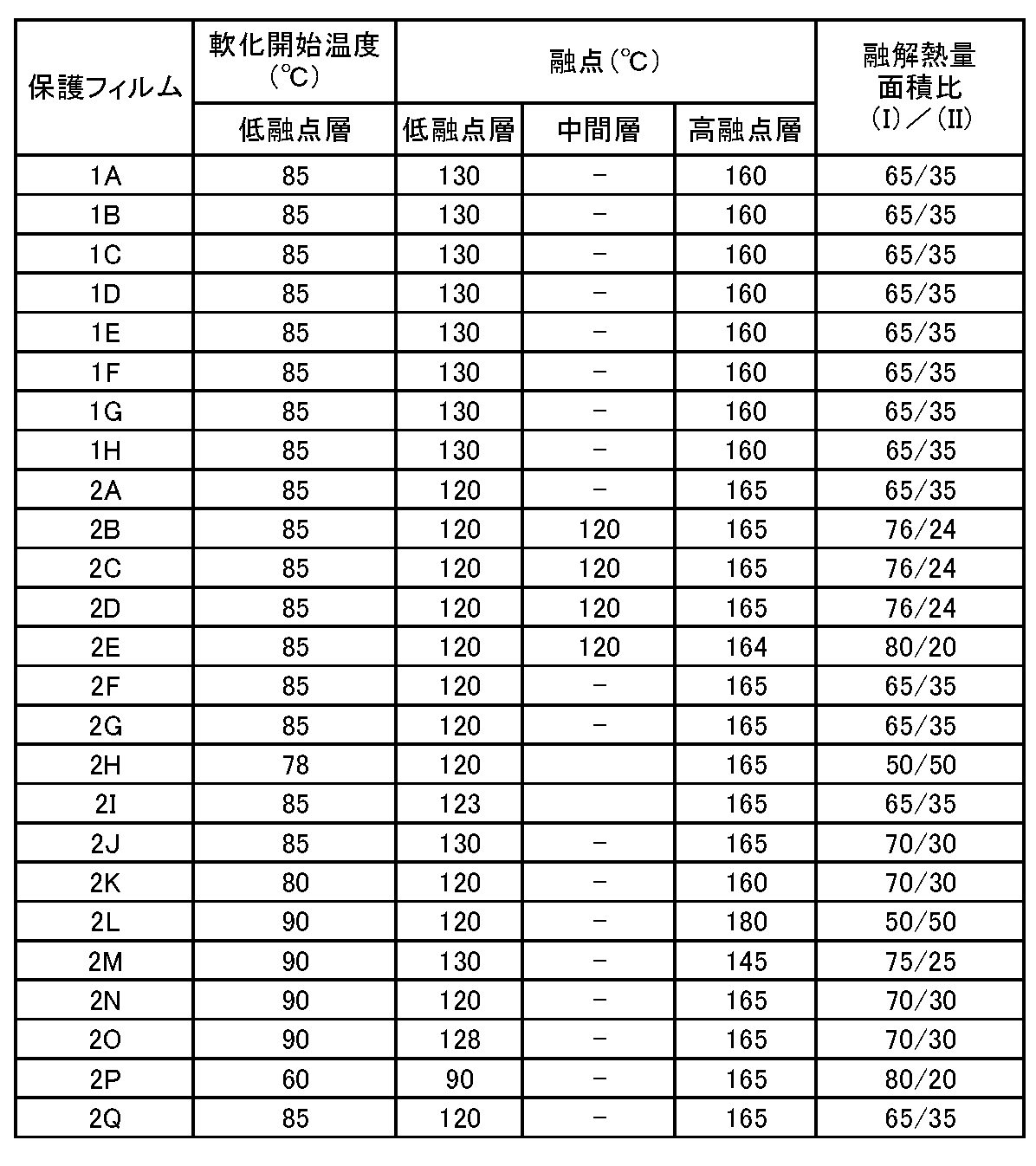
- Table 2 shows the softening start temperature and the heat of fusion area ratio (I) / (II) measured by DSC for the protective film.
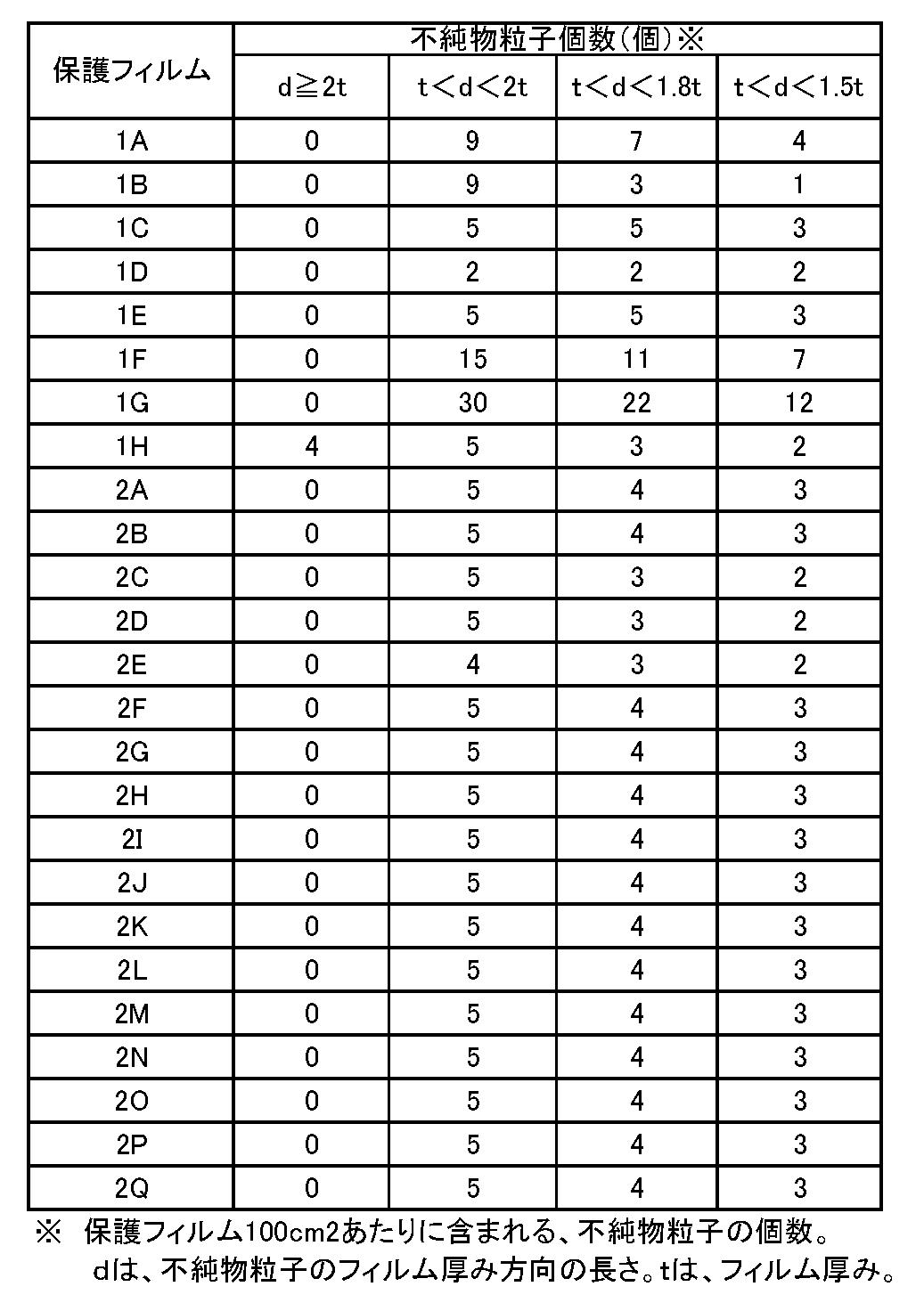
- the number of optical impurity particles is measured, and the length d of the impurity particles in the film thickness direction is 2 t or more, 1 to 2 t, 1 to 1.8 t,
- Table 3 shows the numbers contained in the range of 1 to 1.5 t per 100 cm 2 of film.
- the softening point of the urethane resin contained in the urethane resin solution for the optical function layer was 105 ° C.
- n-butylamine was further added dropwise and reacted at 25 ° C. for 1 hour to obtain a propylene glycol monomethyl ether solution of urethane resin.
- a propylene glycol monomethyl ether solution of urethane resin To this urethane resin solution, 2.0 g of DOW CORNING TORAY L-7001 as a surfactant was added and stirred and mixed at room temperature to obtain a urethane resin solution for an adhesive layer.
- the softening point of the urethane resin contained in the urethane resin solution for the adhesive layer was 150 ° C.
- Example 1> (Creation of optical laminate) A protective film 1A was laminated on one side of a 400 ⁇ m thick polycarbonate sheet to prepare a transparent substrate with a protective film.
- the protective film 1A used here has a two-layer structure of a low melting point layer (thickness 15 ⁇ m) made of low density polyethylene having a melting point of 130 ° C. and a high melting point layer (thickness 15 ⁇ m) made of polypropylene having a melting point of 160 ° C.
- the total thickness t is 30 ⁇ m (see Tables 1 and 2).
- This protective film 1A contains 9 optical impurity particles having a size in the plane direction of 40 ⁇ m or more and a length d in the film thickness direction of 40 ⁇ m or more (1t ⁇ d ⁇ 2t) per 100 cm 2. (See Table 3). Further, for this protective film 1A, the area ratio [(I) / (II)] of the heat of fusion (I) of 80 to 135 ° C. determined by DSC and the heat of fusion (II) of 145 to 175 ° C. was 65 / 35.
- the urethane resin solution for the adhesive layer is applied on the polycarbonate sheet surface (the surface on which the protective film is not laminated) of the transparent substrate at a coating speed of 0.5 m / min.
- the adhesive layer having a thickness of 5 ⁇ m was formed by coating and drying at a drying temperature of 110 ° C. for 3 minutes.
- the urethane resin solution for optical function layer prepared above is applied on an OPP film (stretched polypropylene film) having a thickness of 50 ⁇ m prepared separately at a coating speed of 0.3 m / min, and a drying temperature of 100 ° C. Was dried for 5 minutes to form a functional sheet (corresponding to the optical functional layer) having a thickness of 40 ⁇ m on the OPP film.
- the optical functional layer is placed on the adhesive layer of the transparent substrate formed in advance, and is laminated using a laminate roll, and is composed of protective film / polycarbonate sheet / adhesive layer / functional sheet / OPP film. A laminate ⁇ was obtained.
- a laminate roll obtained by peeling the OPP film from the laminate ⁇ and a polycarbonate sheet with a protective film having an adhesive layer are laminated so that the functional sheet and the adhesive layer on the polycarbonate sheet are joined.
- the laminated sheet thus obtained was allowed to stand at 60 ° C. under vacuum (500 Pa) for 12 hours (degassing step), then heat-treated at 120 ° C. for 2 hours (heating step), and then 70 ° C. and 90%.
- An optical laminate having photochromic properties was obtained by performing a humidification treatment (humidification step) with RH for 20 hours, and finally leaving it at 80 ° C. under vacuum (500 Pa) for 5 hours (drying step).
- the layer structure of this optical laminated body is as follows.
- Protective film / PC sheet / adhesive layer / functional sheet / adhesive layer / PC sheet / protective film (PC sheet is a polycarbonate sheet)
- the peel strength of the functional sheet was 200 N / 25 mm at the initial peel strength and 180 N / 25 mm after the boiling test.
- the maximum absorption wavelength ( ⁇ max) was 585 nm, the color density 1.0, the fading speed 45 seconds, and the durability 93%.
- the peel strength of the protective film was an initial peel strength of 0.5 N / 25 mm, and a post-heat treatment peel strength of 0.5 N / 25 mm.
- the obtained disk-shaped sheet was bent into a spherical shape by hot press molding.
- a convex mold having a diameter of 8 cm and a concave mold, which are a pair of spherical shapes, are mounted on a heat press machine, and the laminate is installed on the concave mold with a fixing jig, and 150 convex and concave molds are provided.
- the optical laminate is heated with a heated convex mold at a pressure of 250 N / cm 2 , left for 5 minutes, cooled to 50 ° C. or less, and removed from the mold to be processed into a spherical shape. (Processed sheet) was obtained. Prior to hot pressing, the laminate was preheated at 80 ° C. for 1 hour under vacuum.
- the protective films on both sides were peeled off from the processed sheet of the obtained optical laminate having a spherical shape, and then placed in a mold of an injection molding machine and heated to 100 ° C.
- the injection molding machine is filled with pellets of polycarbonate resin (Panlite manufactured by Teijin Chemicals Co., Ltd.) preheated at 120 ° C for 5 hours, heated and melted at 300 ° C and 60 rpm, and placed in the mold at an injection pressure of 14000 N / cm 2.
- a plastic lens (optical article) integrated with a polycarbonate resin was produced.
- the lens molding yield (lens appearance evaluation) of the obtained lens was 85%.
- Table 4 shows the results of peel strength of the functional sheet, peel strength of the protective film, photochromic characteristics, and lens molding yield.
- optical impurity fine particles having a length d in the film thickness direction larger than 1.0 t and less than 2.0 t with respect to the thickness t of the protective film are 100 cm 2.
- the molding yield of the lens finally obtained was poor.
- the optical laminated body is bent into a spherical shape by hot press molding.
- Example 6> (Creation of optical laminate) As shown in Table 5, an optical laminate was produced in the same manner as in Example 1 except that the protective film 2A was used. In the obtained optical laminate, the peel strength of the functional sheet (initial peel strength and peel strength after boiling test), the peel strength of the protective film (initial peel strength and peel strength after heating test), photochromic properties (maximum absorption wavelength ⁇ max , Color density, fading speed, and durability) were measured, and the results are shown in Table 6. Moreover, the die-cutting workability of this optical laminate was evaluated, and the results are also shown in Table 6.
- thermo bending processing thermo bending processing
- This vacuum suction processing was carried out by placing a concave mold having a diameter of 90 mm in an atmosphere at 150 ° C. and performing vacuum suction from a hole in the center of the concave mold with a vacuum pump.
- the processing time was about 20 minutes per sheet, and an optical laminate processed into a spherical shape was obtained by removing it from the mold.
- the optical laminate was preheated at 80 ° C. for 1 hour under vacuum.
- a plastic lens is manufactured in the same manner as in Example 1, and the appearance of the lens is evaluated (lens molding yield, defect 1, defect 2, defect 3). The results are shown in Table 6.
- Examples 7 to 22> Using the protective film shown in Table 5, an optical laminate and a lens were produced in the same manner as in Example 6, and the same evaluation as in Example 6 was performed. The results are shown in Table 6.
- Example 23 An optical laminate and a lens were produced in the same manner as in Example 6 except that the protective film 2A was used, and a polarizing film made of polyvinyl alcohol was used as a functional sheet corresponding to the optical functional layer. The same evaluation was performed and the results are shown in Table 6.
- Optical laminated body 3 Transparent substrate 5: Optical functional layer 7: Adhesive layer 9: Protective film 9a: Low melting point layer 9b: High melting point layer 15: Optical impurity particles
Landscapes
- Physics & Mathematics (AREA)
- Thermal Sciences (AREA)
- General Physics & Mathematics (AREA)
- Optics & Photonics (AREA)
- Engineering & Computer Science (AREA)
- Mechanical Engineering (AREA)
- Laminated Bodies (AREA)
Abstract
本発明の光学積層体1は1対の透明基材3、3の間に、光学機能層5がサンドイッチされた基本層構造を有しており、少なくとも一方の透明基材3の表面に保護フィルム9が直接積層されており、保護フィルム9には、光学的不純物粒子15が不可避的に含まれているが、下記条件式: 1.0t<d<2.0t 式中、 tは前記保護フィルム9の厚みであり、 dは前記不純物粒子15のフィルム厚み方向の長さである、 を満足する粗大な光学的不純物粒子15の数が100cm2あたり、10個以下に抑制されていることを特徴とする。
Description
本発明は、フォトクロミック性や偏光性等の光学機能を示す光学機能層を備えた光学積層体に関するものであり、より詳細には、1対の透明基材の間に、光学機能層がサンドイッチされている光学積層体に関するものである。
近年、防眩性を有するサングラスなどに、透明で優れた耐衝撃性を有するポリカーボネートを用いたプラスチック基材の需要が急速に高まっている。そして、このようなプラスチック製サングラスにおいては、フォトクロミック化合物と組み合わせることによって、周囲の明るさに応じて透過率が変化することにより防眩性を調節できるプラスチック製フォトクロミックサングラスが急速に人気を得ている。
例えば、特許文献1には、2枚のポリカーボネートシートの間にフォトクロミック層が積層されている光学積層体が開示されている。
また、特許文献2には、2枚のポリカーボネートの間に偏光層が積層されている光学積層体が開示されている。
また、特許文献2には、2枚のポリカーボネートの間に偏光層が積層されている光学積層体が開示されている。
上記のようなフォトクロミック層や偏光層等の光学機能層を備えた光学積層体は、一般に、熱曲げ加工により、所望の形状に加工される。この熱曲げ加工は、所望の形状に掘り込み加工が施された金型(mold)上に、光学積層体を載置し、加熱環境下(積層体のガラス転移温度近辺の温度下)のもと、加圧あるいは減圧(真空)下で賦形することにより行われる。
また、係る光学積層体は、一般に上記の熱曲げ加工前、もしくは後に、所望の形状に型抜き加工される。
また、係る光学積層体は、一般に上記の熱曲げ加工前、もしくは後に、所望の形状に型抜き加工される。
ところで、ポリカーボネートなどのプラスチックシートには、キズや汚れ、或いは異物がつきやすい。このため、上記熱曲げ加工時や型抜き加工時、或いは保管時、及び輸送時における表面保護を目的として、通常、該プラスチックシート表面には、保護フィルムが設けられる。このような保護フィルムとして、例えば、ポリエチレンやポリプロピレン等のポリオレフィン系フィルムが用いられている。
係る保護フィルムは、光学積層体をメガネレンズ等の最終製品として使用する際には、引き剥がされるものである。
係る保護フィルムは、光学積層体をメガネレンズ等の最終製品として使用する際には、引き剥がされるものである。
例えば、特許文献3には、金型に接する側に配置された第一フィルム層とポリカーボネートシート側に配置された第二フィルム層とを有する保護フィルムが開示されている。
上記の保護フィルムでは、第一フィルム層の融点が150℃以上のポリオレフィン系フィルム層であり、第二フィルム層の融点が125~145℃のポリオレフィン系フィルム層であり、第二フィルム層とポリカーボネートシートとの間には、ポリエチレン系の粘着層が設けられている。係る構造の保護フィルムは、耐熱性に優れており、熱曲げ加工時の保護フィルムの金型表面への付着を有効に防止できるというものである。
上記の保護フィルムでは、第一フィルム層の融点が150℃以上のポリオレフィン系フィルム層であり、第二フィルム層の融点が125~145℃のポリオレフィン系フィルム層であり、第二フィルム層とポリカーボネートシートとの間には、ポリエチレン系の粘着層が設けられている。係る構造の保護フィルムは、耐熱性に優れており、熱曲げ加工時の保護フィルムの金型表面への付着を有効に防止できるというものである。
更には、特許文献4には、基材層と接着剤層とからなる保護フィルムが提案されている。この保護フィルムでは、105~130℃の融解ピーク(A)と160℃~175℃の融解ピーク(B)とを有しており、融解ピークの面積比[(A)/(B)]が35/65~80/20となっている。この保護フィルムを用いることにより、型抜き加工時において、保護フィルムの端部からの糸状物(バリのようなもの)の発生が抑制でき、また、熱曲げ加工による保護フィルムの金型への融着を抑制することができる。
しかしながら、上述した構造を有する従来公知の光学積層体には、熱曲げ加工後において、保護フィルムを引き剥がしたとき、透明基材の表面に凹みが発生するという問題があった。
また、従来公知の光学積層体においては、保護フィルムを引き剥がしたときの所謂糊残り(粘着剤の付着)による外観不良あるいは光学特性の低下という問題があり、さらには、熱曲げ加工時における保護フィルムの金型への融着が生じる問題があった。また、光学積層体の型抜き加工時に、保護フィルム端部の浮きや糸状物が発生し、これらは光学積層体を型抜き加工後に熱曲げ加工に供すと成形不良を引き起こしていた。
また、従来公知の光学積層体においては、保護フィルムを引き剥がしたときの所謂糊残り(粘着剤の付着)による外観不良あるいは光学特性の低下という問題があり、さらには、熱曲げ加工時における保護フィルムの金型への融着が生じる問題があった。また、光学積層体の型抜き加工時に、保護フィルム端部の浮きや糸状物が発生し、これらは光学積層体を型抜き加工後に熱曲げ加工に供すと成形不良を引き起こしていた。
したがって、本発明の目的は、熱曲げ加工後に保護フィルムを引き剥がしたときの透明基材表面に発生する凹みの問題が有効に解決された保護フィルム付き光学積層体を提供することにある。
本発明の他の目的は、保護フィルムを引き剥がしたときの糊残りの問題と同時に、熱曲げ加工時における保護フィルムの金型への融着および、型抜き加工での保護フィルム端部の浮きや糸状物の発生という問題も解決された保護フィルム付き光学積層体を提供することにある。
本発明の他の目的は、保護フィルムを引き剥がしたときの糊残りの問題と同時に、熱曲げ加工時における保護フィルムの金型への融着および、型抜き加工での保護フィルム端部の浮きや糸状物の発生という問題も解決された保護フィルム付き光学積層体を提供することにある。
本発明者らは、熱曲げ加工後における上記凹みの問題について、多くの実験を行い検討した結果、意外にも、保護フィルムの形態に対応して透明基材の表面に凹みが発生するという知見を見出し、本発明を完成させるに至った。
また、熱曲げ加工時における保護フィルムの金型への融着および、型抜き加工での保護フィルム端部の浮きや糸状物の発生に関しては、保護フィルムを低融点層と高融点層とを含む積層構造とすることにより解決し得ることを見出した。
また、熱曲げ加工時における保護フィルムの金型への融着および、型抜き加工での保護フィルム端部の浮きや糸状物の発生に関しては、保護フィルムを低融点層と高融点層とを含む積層構造とすることにより解決し得ることを見出した。
すなわち、本発明によれば、1対の透明基材の間に、光学機能層がサンドイッチされた基本層構造を有しており、少なくとも一方の透明基材の表面に保護フィルムが直接積層されている光学積層体において、
前記保護フィルムには、光学的不純物粒子が不可避的に含まれているが、下記条件式:
1.0t<d<2.0t
式中、
tは前記保護フィルムの厚みであり、
dは前記不純物粒子のフィルム厚み方向の長さである、
を満足する粗大な光学的不純物粒子の数が100cm2あたり、10個以下に抑制されていることを特徴とする光学積層体が提供される。
前記保護フィルムには、光学的不純物粒子が不可避的に含まれているが、下記条件式:
1.0t<d<2.0t
式中、
tは前記保護フィルムの厚みであり、
dは前記不純物粒子のフィルム厚み方向の長さである、
を満足する粗大な光学的不純物粒子の数が100cm2あたり、10個以下に抑制されていることを特徴とする光学積層体が提供される。
上記の光学積層体においては、
(1)前記光学機能層は、光学機能性材料とウレタン樹脂とを含んでなること、
(2)前記光学機能性材料が、フォトクロミック化合物であること、
(3)前記保護フィルムが、オレフィン系樹脂製であること、
(4)前記保護フィルムの厚みが10~150μmの範囲にあること、
(5)前記保護フィルムが、融点が100~125℃の範囲にある低融点層と、融点が150~175℃の範囲にある高融点層とを含んでおり、該低融点層が、前記透明基材の表面に密着していること、
(6)前記低融点層の融点が、123℃以下であること、
が好ましい。
(1)前記光学機能層は、光学機能性材料とウレタン樹脂とを含んでなること、
(2)前記光学機能性材料が、フォトクロミック化合物であること、
(3)前記保護フィルムが、オレフィン系樹脂製であること、
(4)前記保護フィルムの厚みが10~150μmの範囲にあること、
(5)前記保護フィルムが、融点が100~125℃の範囲にある低融点層と、融点が150~175℃の範囲にある高融点層とを含んでおり、該低融点層が、前記透明基材の表面に密着していること、
(6)前記低融点層の融点が、123℃以下であること、
が好ましい。
本発明によればまた、上記光学積層体からなる型抜き加工品あるいは熱曲げ加工品が提供される。
本発明によれば更に、1対の透明基材の間に、光学機能層がサンドイッチされた基本層構造を有しており、少なくとも一方の透明基材の表面に保護フィルムが直接積層されている光学積層体において、前記保護フィルムが、融点が100~125℃の範囲にある低融点層と、融点が150~175℃の範囲にある高融点層とを含んでおり、該低融点層が、前記透明基材の表面に密着していることを特徴とする光学積層体が提供される。
本発明の光学積層体においては、保護フィルムとして粗大な光学的不純物粒子、すなわち、フィルム厚み方向の長さdが保護フィルムの厚みtに対して1.0倍より大きく、かつ、2.0倍未満の光学的不純物粒子の数が100cm2あたり、10個以下に抑制されている点に大きな特徴を有している。このような粗大な光学的不純物の数が少ない保護フィルムを使用することにより、熱曲げ加工後に保護フィルムを引き剥がしたときに透明基材表面に発生する凹みの発生が有効に防止されている。
上記のような保護フィルムの使用により、熱曲げ加工後における透明基材表面に発生する凹みの発生が防止されることは、多くの実験により現象として見出されたものであり、その理由は明確に解明されていないが、本発明者らは、次のように推定している。
透明基材表面に設けられる保護フィルムは、使用時には引き剥がされてしまうものであるため、一般に安価なローグレードの熱可塑性樹脂フィルム、例えば、オレフィン系樹脂フィルムが保護フィルムとして使用されている。このようなローグレードのフィルムは、原料樹脂の溶融不足、フィルム成形時での温度ムラ等に起因してフィッシュアイ(所謂ブツ)と呼ばれる硬く、白く濁たり、逆に光が散乱して光って見える光学的不純物粒子を多く含んでおり、本発明者らは、このような光学的不純物粒子の内、大きなサイズのものに対応して熱曲げ加工時に透明基材表面に凹みが形成されるものと考えている。
すなわち、フォトクロミック化合物等の光学機能性材料を含む光学機能層には硬質の透明基材と接着させるため、該透明基材と比較して低軟化点のバインダ樹脂を含んでいる。このため、保護フィルムが積層されている光学積層体について熱曲げ加工を行うと、透明基材の間にサンドイッチされている光学機能層が軟化した状態で保護フィルムが透明基材表面に押し付けられることとなり、この結果、保護フィルムに存在している大きく硬い光学的不純物粒子の形状が透明基材表面に凹みとして反映されてしまうものと考えられる。
すなわち、フォトクロミック化合物等の光学機能性材料を含む光学機能層には硬質の透明基材と接着させるため、該透明基材と比較して低軟化点のバインダ樹脂を含んでいる。このため、保護フィルムが積層されている光学積層体について熱曲げ加工を行うと、透明基材の間にサンドイッチされている光学機能層が軟化した状態で保護フィルムが透明基材表面に押し付けられることとなり、この結果、保護フィルムに存在している大きく硬い光学的不純物粒子の形状が透明基材表面に凹みとして反映されてしまうものと考えられる。
したがって、本発明では、光学的不純物が小さく、かつ、少ないハイグレードの保護フィルムを用いることにより、熱曲げ加工時における透明基材表面の凹みの発生を有効に防止できる。保護フィルムの形態が熱曲げ加工後の透明基材表面の形態に影響を与えることは従来全く考えられておらず、極めて予想外のことである。
本発明では、保護フィルムとして低融点層と高融点層とを含む積層構造を有しているフィルムを使用することができる。このような積層構造フィルムは、低融点層が透明基材の表面に密着するように設けられる。このため、例えば、型抜き工程により、保護フィルムの端部が透明基材表面から浮いてしまうようなことがなく、このような保護フィルム端部からの糸状物の発生を有効に防止することができる。
また、斯様に低融点層が透明基材の表面にしっかりと密着しているため、必ずしも低融点層に粘着剤を用いる必要がなく、この場合、保護フィルムを容易に透明基材の表面から引き剥がすことができ、糊残り等の問題を生じることがない。
さらに、この態様においては、高融点層が表面側に設けられるため、熱曲げ加工時における保護フィルムの金型表面への融着を有効に防止することができる。
加えるに、上記のように保護フィルム端部の浮きや糸状物の発生が有効に防止されているため、このような浮きや糸状物による成形不良を有効に防止することができる。例えば、糸状物が発生している状態で熱曲げ加工を行うと、糸状物が透明基材表面に反映されてしまい、透明基材表面に凹み等が発生するおそれがあるが、保護フィルムを低融点層を含む積層構造とすることにより、このような透明基材表面の凹みをより確実に防止することができる。また、保護フィルムの端部が浮いている状態で熱曲げ加工(特に減圧吸引加工)を行うと、光学積層体が金型にきれいに密着しないため、所望の形状に加工できなくなるが、こうした保護フィルム端部の浮きを抑制できることにより、光学積層体を所望の形状に加工することができる。
また、斯様に低融点層が透明基材の表面にしっかりと密着しているため、必ずしも低融点層に粘着剤を用いる必要がなく、この場合、保護フィルムを容易に透明基材の表面から引き剥がすことができ、糊残り等の問題を生じることがない。
さらに、この態様においては、高融点層が表面側に設けられるため、熱曲げ加工時における保護フィルムの金型表面への融着を有効に防止することができる。
加えるに、上記のように保護フィルム端部の浮きや糸状物の発生が有効に防止されているため、このような浮きや糸状物による成形不良を有効に防止することができる。例えば、糸状物が発生している状態で熱曲げ加工を行うと、糸状物が透明基材表面に反映されてしまい、透明基材表面に凹み等が発生するおそれがあるが、保護フィルムを低融点層を含む積層構造とすることにより、このような透明基材表面の凹みをより確実に防止することができる。また、保護フィルムの端部が浮いている状態で熱曲げ加工(特に減圧吸引加工)を行うと、光学積層体が金型にきれいに密着しないため、所望の形状に加工できなくなるが、こうした保護フィルム端部の浮きを抑制できることにより、光学積層体を所望の形状に加工することができる。
このように、本発明の光学積層体によれば、熱曲げ加工や型抜き工程等の二次加工時の成形不良を有効に防止することができるため、フォトクロミック性や偏光性等の光学機能性を有するプラスチックレンズ等の二次光学製品を精度よく製造することができる。
本発明の光学積層体の断面構造を示す図1を参照して、全体として1で示す光学積層体は、1対の透明基材3、3の間に光学機能層5がサンドイッチされた基本層構造を有している。上記の基本構造において、光学機能層5は適宜接着層7により透明基材3に接着されている。また、図1に示されているように、透明基材3の表面には保護フィルム9が設けられている。
(透明基材3)
本発明の光学積層体1において、上記の透明基材3としては、所望の色に着色してあっても良いが、後述する光学機能層5の光学機能を阻害しないような透明性を有するもの、例えば、波長500nmの光に対する光透過率が50%以上のものが好適に使用される。
このような透明性を有する基材の例としては、ポリカーボネート樹脂、ポリエチレンテレフタレート樹脂、ナイロン樹脂、トリアセチルセルロース樹脂、アクリル樹脂、ウレタン樹脂、アリル樹脂、エポキシ樹脂、ポリビニルアルコール樹脂などが挙げられる。その中でも、光学機能層等に対する接着性に優れ、射出成形性にも優れているという点で、ポリカーボネート樹脂が好ましい。特にポリカーボネート樹脂は硬質であり、表面が傷付き易いため、保護フィルム9を設けている本発明の光学積層体1には、特に好適である。
本発明の光学積層体1において、上記の透明基材3としては、所望の色に着色してあっても良いが、後述する光学機能層5の光学機能を阻害しないような透明性を有するもの、例えば、波長500nmの光に対する光透過率が50%以上のものが好適に使用される。
このような透明性を有する基材の例としては、ポリカーボネート樹脂、ポリエチレンテレフタレート樹脂、ナイロン樹脂、トリアセチルセルロース樹脂、アクリル樹脂、ウレタン樹脂、アリル樹脂、エポキシ樹脂、ポリビニルアルコール樹脂などが挙げられる。その中でも、光学機能層等に対する接着性に優れ、射出成形性にも優れているという点で、ポリカーボネート樹脂が好ましい。特にポリカーボネート樹脂は硬質であり、表面が傷付き易いため、保護フィルム9を設けている本発明の光学積層体1には、特に好適である。
上記の透明基材3の厚みは、特に制限されず、この光学積層体1の用途に応じて適宜の厚みを有していればよいが、一般的には100~1500μm、特に200~1000μmが好ましい。もちろん、二つの透明基材3、3の厚みは異なっていてもよい。
(光学機能層5)
光学機能層5は、フォトクロミック性や偏光性に代表される光学機能を示す層であり、このような光学機能を示す光学機能性材料がバインダ樹脂に分散された層である。
上記の光学機能性材料としては、フォトクロミック材料や、偏光材料を挙げることができる。
光学機能層5は、フォトクロミック性や偏光性に代表される光学機能を示す層であり、このような光学機能を示す光学機能性材料がバインダ樹脂に分散された層である。
上記の光学機能性材料としては、フォトクロミック材料や、偏光材料を挙げることができる。
フォトクロミック材料としては、それ自体公知のフォトクロミック化合物、例えば、クロメン化合物、フルギミド化合物、スピロオキサジン化合物、スピロピラン化合物等が、単独あるいは二種以上の組み合わせで使用される。
上記のフルギミド化合物、スピロオキサジン化合物、スピロピラン化合物およびクロメン化合物としては、例えば特開平2-28154号公報、特開昭62-288830号公報、WO94/22850号パンフレット、WO96/14596号パンフレットなどに記載されている化合物を挙げることができる。
これらのフォトクロミック化合物の中でも、発色濃度、初期着色、耐久性、退色速度などのフォトクロミック特性の観点から、インデノ(2,1-f)ナフト(2,1-b)ピラン骨格を有するクロメン化合物を1種類以上用いることがより好ましい。さらにこれらクロメン化合物中でもその分子量が540以上の化合物は、発色濃度および退色速度に特に優れるため好適である。
このようなフォトクロミック化合物は、十分なフォトクロミック性(発色濃度、退色速度、フォトクロミック耐久性)を発揮させ、かつ、バインダ樹脂中に均一に分散させ、さらには透明基材3に対する接着性等の観点から、一般にバインダ樹脂100質量部あたり0.1~20質量部、特に0.5~10質量部、最も好ましくは1~7質量部とするのがよい。
このようなフォトクロミック化合物は、十分なフォトクロミック性(発色濃度、退色速度、フォトクロミック耐久性)を発揮させ、かつ、バインダ樹脂中に均一に分散させ、さらには透明基材3に対する接着性等の観点から、一般にバインダ樹脂100質量部あたり0.1~20質量部、特に0.5~10質量部、最も好ましくは1~7質量部とするのがよい。
また、偏光材料としては、ヨウ素、ヨウ素化合物あるいは二色性染料を用いることができる。このような偏光材料は、一般にバインダ樹脂100質量部あたり0.1~5質量部程度使用される。
バインダ樹脂としては、前述した光学機能材料の種類に応じて適宜のものが使用される。
例えば、偏光材料を光学機能材料として用いた場合にはポリビニルアルコール等の水溶性樹脂が好適に使用され、このようなバインダ樹脂に偏光材料を含浸させたものを一軸延伸することにより、偏光性を示す光学機能層5を形成することができる。
また、フォトクロミック化合物を光学機能材料として使用する場合には、ウレタン樹脂や(メタ)アクリル樹脂が好適に使用され、特に透明基材3に対する接着性の観点から、ウレタン樹脂が最も好適である。
例えば、偏光材料を光学機能材料として用いた場合にはポリビニルアルコール等の水溶性樹脂が好適に使用され、このようなバインダ樹脂に偏光材料を含浸させたものを一軸延伸することにより、偏光性を示す光学機能層5を形成することができる。
また、フォトクロミック化合物を光学機能材料として使用する場合には、ウレタン樹脂や(メタ)アクリル樹脂が好適に使用され、特に透明基材3に対する接着性の観点から、ウレタン樹脂が最も好適である。
上記のウレタン樹脂は、分子内にウレタン結合を有する樹脂であり、具体的には、イソホロンジイソシアネート等のジイソシアネート化合物と、ポリカーボネートポリオール、ポリエステルポリオール等のポリオール化合物とを反応させて得られる公知のものが使用され、その中でもジアミン、トリアミン等の鎖延長剤を反応させて得られるウレタン-ウレア樹脂であることが好適である。また、ジアミンあるいはトリアミン鎖延長剤として用いることにより、ウレタン樹脂中にウレア結合(-R-NH-CO-NH-)が導入され、ウレタン-ウレア樹脂となる。
上記のウレタン樹脂としては、例えば、日本国特許第5863317号、特開2012-207198号公報などに記載されているウレタン樹脂を使用することができる。
また、上記のウレタン樹脂に対し、更にイソシアネート結合を分子内に2個以上有するポリイソシアネート化合物を後添加することにより、前記ウレタン樹脂を用いて得られる光学積層体の接着力を向上させることが出来る。これは、前記ウレタン樹脂と別途後添加する前記イソシアネート化合物とが反応し、橋架け構造を有するポリウレタン樹脂が形成され、耐熱性が向上すると共に凝集破壊が起こりにくくなったために、接着性が向上すると考えられる。
上記のウレタン樹脂としては、例えば、日本国特許第5863317号、特開2012-207198号公報などに記載されているウレタン樹脂を使用することができる。
また、上記のウレタン樹脂に対し、更にイソシアネート結合を分子内に2個以上有するポリイソシアネート化合物を後添加することにより、前記ウレタン樹脂を用いて得られる光学積層体の接着力を向上させることが出来る。これは、前記ウレタン樹脂と別途後添加する前記イソシアネート化合物とが反応し、橋架け構造を有するポリウレタン樹脂が形成され、耐熱性が向上すると共に凝集破壊が起こりにくくなったために、接着性が向上すると考えられる。
本発明において特に好適に使用されるウレタン樹脂は、耐熱性が良好であり、かつ、フォトクロミック化合物のフォトクロミック性を阻害しないという点で、80~150℃の軟化点を有しているものが好ましい。
上述した光学機能層5の厚みは、その光学機能に応じて適宜な厚みに設定されるが、通常、10~500μmの範囲にあることが望ましい。
また、このような光学機能層5には、それ自体公知の添加剤が光学機能を損なわない限りの量、例えば、バインダ樹脂100質量部あたり20質量部以下、より好ましくは3質量部以下の量で配合されていてよい。このような添加剤としては、界面活性剤、酸化防止剤、ラジカル補足剤、紫外線安定剤、紫外線吸収剤、離型剤、着色防止剤、帯電防止剤、蛍光染料、染料、顔料、香料、可塑剤等が挙げられる。
(接着層7)
上述した光学機能層5は、適宜、接着層7を介して透明基材3に接合される。
接着層7の形成に使用される接着剤としては、特に制限されないが、前述したウレタン樹脂が接着剤としても好適に使用される。
係る接着層7の厚みは、通常、2~40μm程度である。
上述した光学機能層5は、適宜、接着層7を介して透明基材3に接合される。
接着層7の形成に使用される接着剤としては、特に制限されないが、前述したウレタン樹脂が接着剤としても好適に使用される。
係る接着層7の厚みは、通常、2~40μm程度である。
(保護フィルム9)
保護フィルム9は、透明基材3の表面を保護し、該表面の傷付きや汚れの付着を防止するために使用されるものであり、光学積層体1から最終的に得られる光学物品として使用する際には、透明基材3の表面から引き剥がされるものである。
保護フィルム9は、透明基材3の表面を保護し、該表面の傷付きや汚れの付着を防止するために使用されるものであり、光学積層体1から最終的に得られる光学物品として使用する際には、透明基材3の表面から引き剥がされるものである。
このような保護フィルム9としては、安価な熱可塑性樹脂のフィルム、例えば、アイオノマー、オレフィン樹脂、ポリ塩化ビニル、ポリ塩化ビニリデン、ポリビニルアルコール、ポリエステル、ポリカーボネート、ポリスチレン、ポリアクリロニトリル、ポリウレタン、エチレン酢酸ビニル共重合体、エチレン-ビニルアルコール共重合体、エチレン-メタクリル酸共重合体、ナイロン等が挙げられ、特にコストや耐熱性の観点から、オレフィン樹脂のフィルムが好適に使用される。
このようなオレフィン樹脂としては、ポリプロピレン、ポリエチレン、エチレン-プロピレン共重合体、エチレン-α-オレフィン共重合体およびプロピレン-α-オレフィン共重合体を挙げることができ、これらは適宜ブレンドされて使用することもできる。
このようなオレフィン樹脂としては、ポリプロピレン、ポリエチレン、エチレン-プロピレン共重合体、エチレン-α-オレフィン共重合体およびプロピレン-α-オレフィン共重合体を挙げることができ、これらは適宜ブレンドされて使用することもできる。
ところで、上記のような保護フィルム9は、上述した熱可塑性樹脂のフィルム成形や押出成形によって成形されるため、原料樹脂の溶融が不十分であったり、成形時の熱分布等に起因する溶融ムラによって、光学的不純物粒子(フィッシュアイ)15は白濁していたり、周辺部と異なり不均一であるため、デジタルマイクロスコープやレーザー顕微鏡により視認することができる。
先にも述べた通り、このような不純物粒子15が大きなサイズを有していると、熱曲げ加工時にこの不純物粒子15に対応して透明基材3の表面に凹みが生じることが本発明者らにより確認されている。
従って、本発明では、上記保護フィルム9として、下記条件式:
1.0t<d<2.0t
式中、
tは前記保護フィルム9の厚みであり、
dは前記不純物粒子のフィルム厚み方向の長さである、
を満足する粗大な光学的不純物粒子の数が100cm2あたり、10個以下、特に5個以下に抑制されているものを使用する。すなわち、このような大きな不純物粒子15が存在した状態で熱曲げ加工を行うと、この大きな不純物粒子15が保護フィルム9を通して透明基材3の表面に圧接され、この結果として透明基材3の表面に凹みが形成されることとなる。このため、本発明では、上記のように大きなサイズの不純物粒子15が少ないものを保護フィルム9として使用するわけである。(フィルム厚み方向の長さdが保護フィルム9の厚みtよりも小さいものは、透明基材3の表面形状に影響を与えることはない)
先にも述べた通り、このような不純物粒子15が大きなサイズを有していると、熱曲げ加工時にこの不純物粒子15に対応して透明基材3の表面に凹みが生じることが本発明者らにより確認されている。
従って、本発明では、上記保護フィルム9として、下記条件式:
1.0t<d<2.0t
式中、
tは前記保護フィルム9の厚みであり、
dは前記不純物粒子のフィルム厚み方向の長さである、
を満足する粗大な光学的不純物粒子の数が100cm2あたり、10個以下、特に5個以下に抑制されているものを使用する。すなわち、このような大きな不純物粒子15が存在した状態で熱曲げ加工を行うと、この大きな不純物粒子15が保護フィルム9を通して透明基材3の表面に圧接され、この結果として透明基材3の表面に凹みが形成されることとなる。このため、本発明では、上記のように大きなサイズの不純物粒子15が少ないものを保護フィルム9として使用するわけである。(フィルム厚み方向の長さdが保護フィルム9の厚みtよりも小さいものは、透明基材3の表面形状に影響を与えることはない)
なお、上記の条件を満足する保護フィルム9としては、ハイグレードの高品質フィルムとして市販されているものを使用すればよい。もちろん、入手したフィルムについて、その大きさや数を測定し、上記の条件を満足するものを取捨選択して保護フィルム9として使用することもできる。
このような保護フィルム9の厚みtは、特に制限されるものではないが、その保護機能を十分に発揮させ、かつ、熱曲げ加工性を損なわないようにするために、通常、10~150μm、特に25~110μm、より好ましくは50~80μmの間にあることが望ましい。
また、上述した保護フィルム9は、図2に示されているように、低融点層9aと高融点層9bとを含む積層構造とすることもできる。図2に示されている光学積層体1は、保護フィルム9が低融点層9aと高融点層9bとを含む二層構造となっていることを除けば、図1の光学積層体1と同じ構造を有している。
図2において、低融点層9aは、融点が100~125℃、特に100~123℃の範囲にあるものであり、透明基材3の表面に密着して存在している。すなわち、この低融点層9aは、接着層として機能するものであり、二次加工時等における保護フィルム9の剥がれを防止するための層である。斯様に低融点であり、透明基材3の表面との密着性に優れるため、テルペン樹脂、水添テルペン樹脂、ロジン樹脂、フェノール樹脂等の粘着性付与成分は別に配合しないのが、透明基材3の表面への糊残りの問題を防止する観点から好ましい。このような低融点層9aの形成により、例えば、型抜き加工に際して保護フィルム9の端部が透明基材3の表面から剥がれて浮いてしまうという不都合が有効に防止され(型抜きに使用する刃により、スムーズに切断される)、この結果、保護フィルム9の端部の切断不良に起因するバリのような糸状物の発生が抑制される。また、保護フィルム9の端部の浮きが防止されているため、その後の熱曲げ加工も精度よく行うことができ、例えば、吸引加工により熱曲げ加工を実施した場合においても、光学基材と金型がきれいに密着するために、所望の形状に加工することが出来る。
例えば、低融点層9aの融点が上記範囲よりも低いと、保護フィルム9の引き剥がしが困難となったり、あるいは、保護フィルム9を引き剥がしたとき、低融点層9aの一部が透明基材3の表面に残ってしまい、光学特性が損なわれてしまうおそれがある。
また、低融点層9aの融点が上記範囲よりも高いと、保護フィルム9と透明基材3との密着性が損なわれ、二次加工時に保護フィルム9の剥がれが生じ易くなり、成形不良等の問題が生じてしまう。
例えば、低融点層9aの融点が上記範囲よりも低いと、保護フィルム9の引き剥がしが困難となったり、あるいは、保護フィルム9を引き剥がしたとき、低融点層9aの一部が透明基材3の表面に残ってしまい、光学特性が損なわれてしまうおそれがある。
また、低融点層9aの融点が上記範囲よりも高いと、保護フィルム9と透明基材3との密着性が損なわれ、二次加工時に保護フィルム9の剥がれが生じ易くなり、成形不良等の問題が生じてしまう。
さらに、上記の低融点層9aは、型抜き加工時に使用する刃に対して高い切れ性を示し、型抜き時の端部の浮き等を防止する観点から、その引っ張り強度が30MPa以下、特に20MPa以下であることが好適である。
また、高融点層9bは、融点が150~175℃の範囲にあるものであり、上記低融点層9aの上に位置している。すなわち、この高融点層9bは、保護フィルム9に耐熱性を付与する機能を有しており、例えば、熱曲げ加工時に金型表面への保護フィルム9の融着を防止するという機能を有している。
例えば、高融点層9bの融点が上記範囲よりも低いと、熱曲げ加工に際して金型表面への融着が生じ易くなり、成形不良等を生じ易くなってしまう。また、高融点層9bの上記範囲よりも高いと、二次加工性が損なわれ、熱曲げ加工による成形が困難となるおそれがある。
例えば、高融点層9bの融点が上記範囲よりも低いと、熱曲げ加工に際して金型表面への融着が生じ易くなり、成形不良等を生じ易くなってしまう。また、高融点層9bの上記範囲よりも高いと、二次加工性が損なわれ、熱曲げ加工による成形が困難となるおそれがある。
上述した積層構造を有する保護フィルム9において、透明基材3としてポリカーボネートシートが使用されている場合には、主に低融点層9a由来の80~135℃の熱融解量(I)と、主に高融点層9b由来の145~175℃以下の融解熱量(II)との面積比[(I)/(II)]が60/40~99/1の範囲になるように層構造を形成することが望ましい。すなわち、ポリカーボネートはガラス転移温度が145~150℃であるため、通常、150℃程度の温度で熱曲げ加工等の二次加工が実施される。
なお、上述した低融点層9a、高融点層9bの融点や融解熱量は、DSC(示差走査熱量計)を用いて各層を分離することなくJIS-K7121に準拠して測定することができる。融点はピークトップの値である。
本発明において、低融点層9a及び高融点層9bを形成する樹脂としては、前述した保護フィルム形成用の熱可塑性樹脂の中から所定の融点を有し、かつ、所定の引張り強度を有するようなものが選択され、互いに同種の樹脂により形成されていてもよいし、異種の樹脂により形成されていてもよいが、両層9a、9bの接着性の観点から、いずれもオレフィン系樹脂により形成されていることが望ましい。また、低融点層9aが示す透明基材3との接着性及び高融点層9bが示す耐熱性や表面保護性を最大限活かすという観点から、低融点層9aが低、中及び高密度ポリエチレンやエチレン/α-オレフィン共重合体もしくはこれらのブレンド物からなるエチレン系重合体により形成されており、高融点層9bが、ポリプロピレン、プロピレン/α-オレフィン共重合体及びこれらのブレンド物からなるプロピレン系重合体により形成されていることが最も好適である。
また、上記低融点層9a及び高融点層9bの厚みは、保護フィルム9のトータルの厚みが前述した範囲内(例えば、10~150μm)にあることを条件として、これらの層9a、9bの機能が十分に発揮されるような範囲に設定されていればよい。例えば、低融点層9aの厚みが5~100μm、特に5~30μmの間にあり、高融点層9bの厚みが5~100μm、特に20~100μmの間にあることが好適である。
さらに、上記の保護フィルム9においては、厚み調整や低融点層9aと高融点層9bとの接着性を高めるために、両層9a、9bの間に、前述した保護フィルム用熱可塑性樹脂(特にオレフィン系樹脂)により形成された中間層を設けることもできる。
なお、上述した積層型の保護フィルム9を形成する各層には、その機能を損なわず且つ融点の変動をきたさない限りにおいて、酸化防止剤、光安定剤、界面活性剤(帯電防止剤)、導電材等を少量配合することもできる。
このような、積層型の保護フィルム9は、各層を形成する樹脂を用いの共押出により作成される。
上述した図1あるいは図2に示された本発明の光学積層体1においては、種々の設計変更が可能である。例えば、図1および図2の例では、保護フィルム9は1対の透明基材3、3の両方に設けられているが、一方の透明基材3にのみ設けることも可能である。また、透明基材3の表面には、ハードコート層や反射防止層等が形成されていてもよい。
(光学積層体1の製造)
図1及び図2に示される本発明の光学積層体1は、予め透明基材3を形成する透明シートの一方の面に保護フィルム9を熱圧着等により貼付けて、保護フィルム付透明シートを作成し、この透明シートの他方の面に光学機能層5を積層することにより製造することができる。
光学機能層5の積層は、例えば、光学機能層5を形成するためのバインダ樹脂(あるいはそのプレポリマー)及び光学機能材料が有機溶媒中に分散ないし溶解した塗工液を調製し、この塗工液を上記透明シートの他方の面に塗布し、加熱乾燥することにより行うことができる。
また、光学機能層5と透明基材3との間に接着層7を介在させる場合には、接着層形成用の樹脂(例えば、ウレタン樹脂あるいはそのプレポリマー)を有機溶媒に溶解ないし分散した塗工液を調製し、この塗工液を前述した保護フィルム付透明シートの他方の面に塗布した後、上記と同様に光学機能層5を積層すればよい。
図1及び図2に示される本発明の光学積層体1は、予め透明基材3を形成する透明シートの一方の面に保護フィルム9を熱圧着等により貼付けて、保護フィルム付透明シートを作成し、この透明シートの他方の面に光学機能層5を積層することにより製造することができる。
光学機能層5の積層は、例えば、光学機能層5を形成するためのバインダ樹脂(あるいはそのプレポリマー)及び光学機能材料が有機溶媒中に分散ないし溶解した塗工液を調製し、この塗工液を上記透明シートの他方の面に塗布し、加熱乾燥することにより行うことができる。
また、光学機能層5と透明基材3との間に接着層7を介在させる場合には、接着層形成用の樹脂(例えば、ウレタン樹脂あるいはそのプレポリマー)を有機溶媒に溶解ないし分散した塗工液を調製し、この塗工液を前述した保護フィルム付透明シートの他方の面に塗布した後、上記と同様に光学機能層5を積層すればよい。
前述の方法により得られた本発明の光学積層体1は、そのまま二次加工等に使用することもできるが、得られた光学積層体1の密着性向上のため、また二次加工時での発泡等を防止するために、二次加工に先立って以下の処理を行っておくことが好ましい。
例えば、製造直後の光学積層体1を20~70℃の温度で4時間以上常圧もしくは減圧下で静置し、脱気することが好ましい。さらに、この静置した積層体を60~130℃の温度下、30分以上3時間以下放置しておくことが好ましい。これにより、二次加工時の発泡を有効に防止することができる。
また、光学機能層5に、ウレタン樹脂(ウレタン-ウレア樹脂)に加えてイソシアネート化合物が添加されている場合には、架橋密度を高め、光学機能層5と透明基材3との接着性を高めるために、室温~100℃の温度、及び30~100%RHの湿度下で加湿処理されることが好ましい。さらに、このような加湿処理が行われたときには、常圧下、もしくは真空下において、40~130℃で静置することにより、光学積層体1中に存在する過剰の水分を除去することができる。
例えば、製造直後の光学積層体1を20~70℃の温度で4時間以上常圧もしくは減圧下で静置し、脱気することが好ましい。さらに、この静置した積層体を60~130℃の温度下、30分以上3時間以下放置しておくことが好ましい。これにより、二次加工時の発泡を有効に防止することができる。
また、光学機能層5に、ウレタン樹脂(ウレタン-ウレア樹脂)に加えてイソシアネート化合物が添加されている場合には、架橋密度を高め、光学機能層5と透明基材3との接着性を高めるために、室温~100℃の温度、及び30~100%RHの湿度下で加湿処理されることが好ましい。さらに、このような加湿処理が行われたときには、常圧下、もしくは真空下において、40~130℃で静置することにより、光学積層体1中に存在する過剰の水分を除去することができる。
(光学積層体1の二次加工)
上記のような処理が行われた本発明の光学積層体1は、通常、二次加工により目的とする光学物品の形態に成形される。例えば、光学積層体1を所望の形状に型抜きし(型抜き加工)、次いで熱曲げ加工によりレンズやサングラス、ゴーグル等に適用される球面形状が形成される。
上記のような処理が行われた本発明の光学積層体1は、通常、二次加工により目的とする光学物品の形態に成形される。例えば、光学積層体1を所望の形状に型抜きし(型抜き加工)、次いで熱曲げ加工によりレンズやサングラス、ゴーグル等に適用される球面形状が形成される。
上記の型抜き加工には、トムソン刃、ピナクル刃、彫刻刃、エッチング刃などの刃が使用されるが、加工安定性、経済性の観点からトムソン刃を用いることが好ましい。トムソン刃の形状としては、両刃、片刃、2段刃、3段刃、片2段刃などが挙げられ、刃先の刃角としては25~60°の範囲が好ましい。
刃の厚みとしては0.3~2.0mmが好ましく、材質はショア硬度30~90の全鋼であることが好ましい。また、ショア硬度に関しては、刃先の硬度だけを高くして、切れ味を調整することも可能である。
本発明の光学積層体1を、トムソン刃により抜き加工を行う場合には、光学積層体1に貼り付けられている保護フィルム9の切断性を考慮し、刃角が45°以下の刃を用いることがより好ましく、最も好ましくは30°以下の刃である。使用するトムソン刃の刃角が60°を超える場合、保護フィルム9の切断性が低下するため、光学積層体1の端部に保護フィルムが9伸びて糸状物が発生したり、または保護フィルム9の端部の浮きが発生し、最終的に得られるプラスチックレンズの不良、及び収率低下の原因となる場合がある。
また、型抜き加工時の圧力は、型抜きをする光学積層体1の材料によって適宜決定すれば良いが、本発明の光学積層体1については、1枚当たり500~1000kgの圧力をかけて型抜きをすることが好ましい。
本発明の光学積層体1では、例えば図2に示されるような積層構造を有する保護フィルム9が使用されているときには、この型抜き加工時での保護フィルム9端部の浮きが有効に防止されているため、バリのような糸状物の発生が有効に抑制される。例えば、この光学積層体1を円形に型抜きした際に、外縁部(端部)に生成する長さ2mm以上の糸状物の発生が有効に抑制されている。すなわち、後述する実施例にも示されているように、この光学積層体1を直径80mmに型抜きした際の上記糸状物の個数が20個以下となっている。
なお、糸状物の測定は、デジタルマイクロスコープ(キーエンス社製、VHX-2000)を用いて、直径80mmの円形状に型抜きされたシートの外周に存在する長さ2mm以上の糸状物を確認し、当該糸状物の個数を数えることにより、測定される。
なお、糸状物の測定は、デジタルマイクロスコープ(キーエンス社製、VHX-2000)を用いて、直径80mmの円形状に型抜きされたシートの外周に存在する長さ2mm以上の糸状物を確認し、当該糸状物の個数を数えることにより、測定される。
また、熱曲げ加工は、所定の金型を用いての熱プレス加工、加圧加工、減圧吸引加工等によって行われる。特に、減圧吸引加工を行った際には、本発明の光学積層体は、保護フィルム端部の浮きが抑制されているため、金型によりきれいに密着させることができ、その成型加工性を大きく改善できるため好ましい。
熱プレス加工は、先ず、熱プレス機に、所望する球面形状の凸型の金型と凹型の金型を装着し、両金型の間に該光学積層体1を固定治具で押さえつけ、凸型及び凹型の金型を加熱する。次いで、光学積層体1の両側から、この加熱した金型でプレスすることで、所望の球面形状に曲げ加工することができる。また、熱プレスする場合には、凹型の金型を用いず、凸型の金型のみを用いて、曲げ加工することも可能である。熱プレス加工する場合には、金型のみではなく、光学積層体1を含めた熱プレスを行う雰囲気全体を加熱して実施してもよい。
熱プレス加工は、先ず、熱プレス機に、所望する球面形状の凸型の金型と凹型の金型を装着し、両金型の間に該光学積層体1を固定治具で押さえつけ、凸型及び凹型の金型を加熱する。次いで、光学積層体1の両側から、この加熱した金型でプレスすることで、所望の球面形状に曲げ加工することができる。また、熱プレスする場合には、凹型の金型を用いず、凸型の金型のみを用いて、曲げ加工することも可能である。熱プレス加工する場合には、金型のみではなく、光学積層体1を含めた熱プレスを行う雰囲気全体を加熱して実施してもよい。
加圧加工は、所望の球面形状の凹型金型を有する装置を用いる。この凹型金型に対して本発明の光学積層体1を固定治具で固定化し、光学積層体1の下面側に圧縮空気を注入できる金型をかぶせ、これら全体をヒータで加熱する。次いで、圧縮空気を光学積層体1下面側から注入し、凹型金型の形状に変形させる。
減圧吸引加工は、加圧加工と同様に所望の球面形状の凹型金型を有する装置を用いる。この凹型金型に本発明の光学積層体1を設置するか、もしくは固定治具で固定化し、これら全体をヒータで加熱する。次いで、凹型金型内部から減圧吸引することで、凹型金型の形状に光学積層体1を変形させる。
また、加圧加工と減圧吸引加工を併用しての熱曲げ加工により、光学積層体1を賦形することもできる。
また、加圧加工と減圧吸引加工を併用しての熱曲げ加工により、光学積層体1を賦形することもできる。
上述した熱曲げ加工する際の温度は、光学積層体1に使用されている透明基材3の材質によって適宜、決定すれば良いが、120~200℃の温度で実施することが好ましい。
本発明の光学積層体1では、保護フィルム9として大きな光学的不純物粒子の数が少ないものが選択されて使用されているため、上記の熱曲げ加工に対して透明基材3の表面での凹みの発生が有効に抑制されており、保護フィルム9を剥がした場合においての外観不良が有効に防止され、その優れた光学特性が安定に発揮される。
なお、上記のような熱曲げ加工は、型抜き加工前に行うこともできる。
上記のように二次加工が行われた光学積層体1は、そのまま光学物品として販売することもでき、保護フィルム9を引き剥がして光学物品として使用することができる。また、この保護フィルムを引き剥がした後、所定の光学基材と一体化させてレンズ等の光学物品として使用することもできる。
光学基材との一体化は、保護フィルム9が剥がされた光学積層体1を所定の成形型内に装着し、所謂インナーモールドによる射出成形等によって、光学基材を形成するポリマー(例えば、ポリカーボネート)を型内に充填し、光学基材の成形と同時に行うことができる。このように形成された光学基材の表面(光学積層体1の透明基材3の表面)は、適宜ハードコート層を形成したり、SiO2、TiO2、ZrO2等の金属酸化物の薄膜の蒸着や有機高分子体の薄膜の塗布等による反射防止処理、帯電防止処理等の加工や二次処理を施すこともできる。
光学基材との一体化は、保護フィルム9が剥がされた光学積層体1を所定の成形型内に装着し、所謂インナーモールドによる射出成形等によって、光学基材を形成するポリマー(例えば、ポリカーボネート)を型内に充填し、光学基材の成形と同時に行うことができる。このように形成された光学基材の表面(光学積層体1の透明基材3の表面)は、適宜ハードコート層を形成したり、SiO2、TiO2、ZrO2等の金属酸化物の薄膜の蒸着や有機高分子体の薄膜の塗布等による反射防止処理、帯電防止処理等の加工や二次処理を施すこともできる。
本発明を、次の実験例で説明する。
なお、以下の実験において、光学積層体、或いは該光学積層体を加工して得られたレンズについての各種特性の測定もしくは評価は以下の方法によって行った。
なお、以下の実験において、光学積層体、或いは該光学積層体を加工して得られたレンズについての各種特性の測定もしくは評価は以下の方法によって行った。
<機能性シートの剥離強度>
各実施例或いは比較例で作成された光学積層体から保護フィルムを引き剥がした後、25×100mmの大きさに裁断し、これを試験片として、試験機(オートグラフAGS-500NX、島津製作所製)に装着し、クロスヘッドスピード100mm/minで引張り試験を行い、光学積層体中の透明基材(ポリカーボネートシート)と機能性シート(光学機能層に相当)との初期剥離強度を測定した。
また、上記試験片を、沸騰した蒸留水中に1時間浸漬させた後、同様にして透明基材と機能性シートとの剥離強度(煮沸試験後剥離強度)を測定した。
各実施例或いは比較例で作成された光学積層体から保護フィルムを引き剥がした後、25×100mmの大きさに裁断し、これを試験片として、試験機(オートグラフAGS-500NX、島津製作所製)に装着し、クロスヘッドスピード100mm/minで引張り試験を行い、光学積層体中の透明基材(ポリカーボネートシート)と機能性シート(光学機能層に相当)との初期剥離強度を測定した。
また、上記試験片を、沸騰した蒸留水中に1時間浸漬させた後、同様にして透明基材と機能性シートとの剥離強度(煮沸試験後剥離強度)を測定した。
<保護フィルムの剥離強度>
保護フィルムを引き剥がさずに、上記と同様の試験片を作成し、保護フィルムと透明基材(ポリカーボネートシート)との初期剥離強度を測定した。また、上記試験片を150℃の雰囲気中に30分保持することにより、加熱処理を行い、この後、上記と同様に剥離強度(加熱処理後の剥離強度)を測定した。
保護フィルムを引き剥がさずに、上記と同様の試験片を作成し、保護フィルムと透明基材(ポリカーボネートシート)との初期剥離強度を測定した。また、上記試験片を150℃の雰囲気中に30分保持することにより、加熱処理を行い、この後、上記と同様に剥離強度(加熱処理後の剥離強度)を測定した。
<フォトクロミック特性>
光学積層体から保護フィルムを引き剥がした後、(株)浜松ホトニクス製のキセノンランプL-2480(300W)SHL-100を、エアロマスフィルター(コーニング社製)を介して23℃、積層体表面でのビーム強度365nm=2.4mW/cm2、245nm=24μW/cm2で120秒間照射して発色させ、下記のフォトクロミック特性を測定した。
1)最大吸収波長(λmax):
(株)大塚電子工業製の分光光度計(瞬間マルチチャンネルフォトディレクターMCPD1000)により求めた発色後の最大吸収波長である。該最大吸収波長は、発色時の色調に関係する。
2)発色濃度〔ε(120)-ε(0)〕:
前記最大吸収波長における、120秒間照射した後の吸光度ε(120)と最大吸収波長における未照射時の吸光度ε(0)との差。この値が高いほどフォトクロミック性が優れていると言える。
3)退色速度〔t1/2(秒)〕:
120秒間照射後、光の照射をとめたときに、試料の前記最大波長における吸光度が〔ε(120)-ε(0)〕の1/2まで低下するのに要する時間。この時間が短いほどフォトクロミック性が優れているといえる。
4)耐久性(%)=〔(A96/A0)×100〕:
光照射による発色の耐久性を評価するために次の劣化促進試験を行った。すなわち、得られた積層体をスガ試験器(株)製キセノンウェザーメーターX25により96時間促進劣化させた。その後、前記発色濃度の評価を試験の前後で行い、試験前の発色濃度(A0)および試験後の発色濃度(A96)を測定し、〔(A96)/A0〕×100〕の値を残存率(%)とし、発色の耐久性の指標とした。残存率が高いほど発色の耐久性が高い。
光学積層体から保護フィルムを引き剥がした後、(株)浜松ホトニクス製のキセノンランプL-2480(300W)SHL-100を、エアロマスフィルター(コーニング社製)を介して23℃、積層体表面でのビーム強度365nm=2.4mW/cm2、245nm=24μW/cm2で120秒間照射して発色させ、下記のフォトクロミック特性を測定した。
1)最大吸収波長(λmax):
(株)大塚電子工業製の分光光度計(瞬間マルチチャンネルフォトディレクターMCPD1000)により求めた発色後の最大吸収波長である。該最大吸収波長は、発色時の色調に関係する。
2)発色濃度〔ε(120)-ε(0)〕:
前記最大吸収波長における、120秒間照射した後の吸光度ε(120)と最大吸収波長における未照射時の吸光度ε(0)との差。この値が高いほどフォトクロミック性が優れていると言える。
3)退色速度〔t1/2(秒)〕:
120秒間照射後、光の照射をとめたときに、試料の前記最大波長における吸光度が〔ε(120)-ε(0)〕の1/2まで低下するのに要する時間。この時間が短いほどフォトクロミック性が優れているといえる。
4)耐久性(%)=〔(A96/A0)×100〕:
光照射による発色の耐久性を評価するために次の劣化促進試験を行った。すなわち、得られた積層体をスガ試験器(株)製キセノンウェザーメーターX25により96時間促進劣化させた。その後、前記発色濃度の評価を試験の前後で行い、試験前の発色濃度(A0)および試験後の発色濃度(A96)を測定し、〔(A96)/A0〕×100〕の値を残存率(%)とし、発色の耐久性の指標とした。残存率が高いほど発色の耐久性が高い。
<型抜き加工性評価>
得られた光学積層体を型抜き加工に付して、径80mmの円板状シート20枚を作製した。円板状シート端部に0.5mm幅以上の保護フィルムの浮きが、外周の4分の1以下である円板状シートの枚数を良品とし、良品の円板状シートの割合を良品取得率として算出した。評価は、目視により評価した。
この良品取得率が高いほど光学積層体は型抜き加工性に優れている。
得られた光学積層体を型抜き加工に付して、径80mmの円板状シート20枚を作製した。円板状シート端部に0.5mm幅以上の保護フィルムの浮きが、外周の4分の1以下である円板状シートの枚数を良品とし、良品の円板状シートの割合を良品取得率として算出した。評価は、目視により評価した。
この良品取得率が高いほど光学積層体は型抜き加工性に優れている。
<レンズ外観評価>
光学積層体を加工して得られたレンズに、不良箇所が存在するかどうかを目視及びデジタルマイクロスコープ(キーエンス社製、VHX-2000)にて、下記の評価を行った。
なお、目視で容易に確認できる不良は、レンズ端部に生じる形状不良であり、この不良は、主として保護フィルム端部の浮きが原因と推定される。
(レンズ成型収率)
デジタルマイクロスコープにより、得られたレンズに、不良箇所が存在するかどうかを観察し、レンズ20枚に対する、良品レンズの割合をレンズ成型収率として算出した。
(不良1)
レンズ表面をデジタルマイクロスコープにより観察して確認される不良品の発生数を測定した。
直径30μm以上の凹凸が存在しているものを不良レンズとし、20枚あたりの不良品枚数として示した。この不良は、光学的不純物微粒子に主に由来する。
(不良2)
目視によりレンズ端部の形状不良を観察し、形状不良を有するものを不良レンズとし、20枚あたりの不良品枚数として示した。この不良は、減圧吸引時において保護フィルム端部の浮きがあることを主原因として発生する。
(不良3)
レンズ表面の糊残りを目視により観察し、糊残りが確認されたものを不良レンズとし、20枚あたりの不良品枚数として示した。
光学積層体を加工して得られたレンズに、不良箇所が存在するかどうかを目視及びデジタルマイクロスコープ(キーエンス社製、VHX-2000)にて、下記の評価を行った。
なお、目視で容易に確認できる不良は、レンズ端部に生じる形状不良であり、この不良は、主として保護フィルム端部の浮きが原因と推定される。
(レンズ成型収率)
デジタルマイクロスコープにより、得られたレンズに、不良箇所が存在するかどうかを観察し、レンズ20枚に対する、良品レンズの割合をレンズ成型収率として算出した。
(不良1)
レンズ表面をデジタルマイクロスコープにより観察して確認される不良品の発生数を測定した。
直径30μm以上の凹凸が存在しているものを不良レンズとし、20枚あたりの不良品枚数として示した。この不良は、光学的不純物微粒子に主に由来する。
(不良2)
目視によりレンズ端部の形状不良を観察し、形状不良を有するものを不良レンズとし、20枚あたりの不良品枚数として示した。この不良は、減圧吸引時において保護フィルム端部の浮きがあることを主原因として発生する。
(不良3)
レンズ表面の糊残りを目視により観察し、糊残りが確認されたものを不良レンズとし、20枚あたりの不良品枚数として示した。
<保護フィルム>
それぞれ、融点の異なる各種樹脂もしくは樹脂混合物を用いて作成された二層(低融点層/高融点層)或いは三層(低融点層/中間層/高融点層)の保護フィルム1A~1H及び2A~2Rを用意した。各保護フィルムの材質、引張強度、及び厚みを表1に示した。
なお、表1において使用されている略号は以下の通りである。
LDPE:低密度ポリエチレン
HDPE:高密度ポリエチレン
PP:ポリプロピレン
LDHDmix:低密度ポリエチレンと高密度ポリエチレンとの混合物
PPLDmix:ポリプロピレンと低密度ポリエチレンとの混合物
PVCL:ポリ塩化ビニル
ADLDPE-HDPEmix:
水添テルペン樹脂5重量%含有低密度ポリエチレンと高密度ポリエチ
レンとの混合物
PEVAC:ポリエチレン・酢酸ビニル共重合体
なお、低密度ポリエチレン(LDPE)としては、融点が130℃または120℃のものが使用されている。
また、ポリプロピレン(PP)としては、融点が160℃または165℃のものが使用されている。
それぞれ、融点の異なる各種樹脂もしくは樹脂混合物を用いて作成された二層(低融点層/高融点層)或いは三層(低融点層/中間層/高融点層)の保護フィルム1A~1H及び2A~2Rを用意した。各保護フィルムの材質、引張強度、及び厚みを表1に示した。
なお、表1において使用されている略号は以下の通りである。
LDPE:低密度ポリエチレン
HDPE:高密度ポリエチレン
PP:ポリプロピレン
LDHDmix:低密度ポリエチレンと高密度ポリエチレンとの混合物
PPLDmix:ポリプロピレンと低密度ポリエチレンとの混合物
PVCL:ポリ塩化ビニル
ADLDPE-HDPEmix:
水添テルペン樹脂5重量%含有低密度ポリエチレンと高密度ポリエチ
レンとの混合物
PEVAC:ポリエチレン・酢酸ビニル共重合体
なお、低密度ポリエチレン(LDPE)としては、融点が130℃または120℃のものが使用されている。
また、ポリプロピレン(PP)としては、融点が160℃または165℃のものが使用されている。
上記の保護フィルムについて、DSCにより測定した軟化開始温度及び融解熱量面積比(I)/(II)を表2に示した。
また、上記の保護フィルムについて、光学的不純物粒子の個数を測定し、該不純物粒子のフィルム厚み方向の長さdが、フィルム厚みtに対して2t以上、1~2t、1~1.8t、1~1.5tの範囲にあるものについて、フィルム100cm2あたりに含まれる数を表3に示した。
また、上記の保護フィルムについて、光学的不純物粒子の個数を測定し、該不純物粒子のフィルム厚み方向の長さdが、フィルム厚みtに対して2t以上、1~2t、1~1.8t、1~1.5tの範囲にあるものについて、フィルム100cm2あたりに含まれる数を表3に示した。

(光学機能層用ウレタン樹脂溶液の調製)
撹拌羽、冷却管、温度計、窒素ガス導入管を有する三つ口フラスコに、
数平均分子量800のポリカーボネートジオール 251.9g
イソホロンジイソシアネート 100g
を仕込み、窒素雰囲気下、110℃で7時間反応させ、プレポリマーを合成した。
反応終了後、反応液を30℃付近まで冷却し、THF1515gに溶解させ、次いで、鎖延長剤であるビス-(4-アミノシクロヘキシル)メタン23.6gを滴下し、25℃で1時間反応させた。
その後さらに、1,2,2,6,6-ペンタメチル-4-アミノピペリジン7.7gを滴下し、25℃で1時間反応させることにより、ウレタン樹脂溶液を得た。
このウレタン樹脂溶液に、
フォトクロミック化合物 11.5g
4,4’-メチレンビス(シクロヘキシルイソシアネート)の異性体
混合物 40g
エチレンビス(オキシエチレン)ビス[3-(5-tert-ブチル
-4-ヒドロキシ-m-トリル)プロピオネート]
(酸化防止剤) 4g
DOW CORNING TORAY L-7001
(界面活性剤) 0.6g
を添加し、室温で攪拌・混合を行い、光学機能層用のウレタン樹脂溶液を得た。
撹拌羽、冷却管、温度計、窒素ガス導入管を有する三つ口フラスコに、
数平均分子量800のポリカーボネートジオール 251.9g
イソホロンジイソシアネート 100g
を仕込み、窒素雰囲気下、110℃で7時間反応させ、プレポリマーを合成した。
反応終了後、反応液を30℃付近まで冷却し、THF1515gに溶解させ、次いで、鎖延長剤であるビス-(4-アミノシクロヘキシル)メタン23.6gを滴下し、25℃で1時間反応させた。
その後さらに、1,2,2,6,6-ペンタメチル-4-アミノピペリジン7.7gを滴下し、25℃で1時間反応させることにより、ウレタン樹脂溶液を得た。
このウレタン樹脂溶液に、
フォトクロミック化合物 11.5g
4,4’-メチレンビス(シクロヘキシルイソシアネート)の異性体
混合物 40g
エチレンビス(オキシエチレン)ビス[3-(5-tert-ブチル
-4-ヒドロキシ-m-トリル)プロピオネート]
(酸化防止剤) 4g
DOW CORNING TORAY L-7001
(界面活性剤) 0.6g
を添加し、室温で攪拌・混合を行い、光学機能層用のウレタン樹脂溶液を得た。
なお、フォトクロミック化合物としては、以下の式で表されるものを使用した。
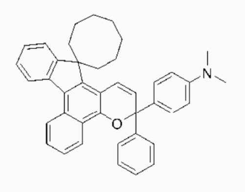
また、上記の光学機能層用ウレタン樹脂溶液に含まれるウレタン樹脂の軟化点は、105℃であった。
(接着層用ウレタン樹脂溶液)
撹拌羽、冷却管、温度計、窒素ガス導入管を有する三つ口フラスコに、
数平均分子量1000のポリカーボネートジオール 220g
イソホロンジイソシアネート 100g
を仕込み、窒素雰囲気下、110℃で7時間反応させ、プレポリマーを合成した。
反応終了後、反応液を30℃付近まで冷却し、プロピレングリコール-モノメチルエーテル 1550gに溶解させ、次いで、鎖延長剤であるイソホロンジアミン 36gを滴下し、25℃で1時間反応させた。
その後さらに、n-ブチルアミン 2gを滴下し、25℃で1時間反応させることにより、ウレタン樹脂のプロピレングリコール-モノメチルエーテル溶液を得た。
このウレタン樹脂の溶液に、界面活性剤としてDOW CORNING TORAY L-7001 2.0gを添加し、室温で攪拌・混合を行い、接着層用ウレタン樹脂溶液を得た。
この接着層用ウレタン樹脂溶液に含まれるウレタン樹脂の軟化点は150℃であった。
撹拌羽、冷却管、温度計、窒素ガス導入管を有する三つ口フラスコに、
数平均分子量1000のポリカーボネートジオール 220g
イソホロンジイソシアネート 100g
を仕込み、窒素雰囲気下、110℃で7時間反応させ、プレポリマーを合成した。
反応終了後、反応液を30℃付近まで冷却し、プロピレングリコール-モノメチルエーテル 1550gに溶解させ、次いで、鎖延長剤であるイソホロンジアミン 36gを滴下し、25℃で1時間反応させた。
その後さらに、n-ブチルアミン 2gを滴下し、25℃で1時間反応させることにより、ウレタン樹脂のプロピレングリコール-モノメチルエーテル溶液を得た。
このウレタン樹脂の溶液に、界面活性剤としてDOW CORNING TORAY L-7001 2.0gを添加し、室温で攪拌・混合を行い、接着層用ウレタン樹脂溶液を得た。
この接着層用ウレタン樹脂溶液に含まれるウレタン樹脂の軟化点は150℃であった。
<実施例1>
(光学積層体の作成)
厚み400μmのポリカーボネートシートの片面に保護フィルム1Aを積層して保護フィルム付透明基材を作成した。
なお、ここで使用した保護フィルム1Aは、融点が130℃の低密度ポリエチレンによる低融点層(厚み15μm)と融点が160℃のポリプロピレンの高融点層(厚み15μm)との二層構造を有しており、そのトータル厚みtが30μmである(表1、表2参照)。この保護フィルム1Aにおいて、平面方向の大きさが40μm以上、フィルム厚み方向の長さdが40μm以上(1t<d<2t)である光学的不純物粒子を、100cm2あたり9個含有するものである(表3参照)。
また、この保護フィルム1Aについて、DSCにより求めた80~135℃の融解熱量(I)と、145~175℃の融解熱量(II)との面積比[(I)/(II)]は65/35であった。
(光学積層体の作成)
厚み400μmのポリカーボネートシートの片面に保護フィルム1Aを積層して保護フィルム付透明基材を作成した。
なお、ここで使用した保護フィルム1Aは、融点が130℃の低密度ポリエチレンによる低融点層(厚み15μm)と融点が160℃のポリプロピレンの高融点層(厚み15μm)との二層構造を有しており、そのトータル厚みtが30μmである(表1、表2参照)。この保護フィルム1Aにおいて、平面方向の大きさが40μm以上、フィルム厚み方向の長さdが40μm以上(1t<d<2t)である光学的不純物粒子を、100cm2あたり9個含有するものである(表3参照)。
また、この保護フィルム1Aについて、DSCにより求めた80~135℃の融解熱量(I)と、145~175℃の融解熱量(II)との面積比[(I)/(II)]は65/35であった。
まず、コーター(テスター産業製)を用いて、接着層用ウレタン樹脂溶液を、上記の透明基材のポリカーボネートシート表面(保護フィルムが積層されていない面)に、塗工速度0.5m/minで塗工し、乾燥温度110℃で3分間乾燥させることにより、膜厚5μmの接着層を形成した。
また、別途用意された厚み50μmのOPPフィルム(延伸ポリプロピレンフィルム)上に、前記で作成された光学機能層用ウレタン樹脂溶液を、塗工速度0.3m/minで塗工し、乾燥温度100℃で5分間乾燥させることにより、OPPフィルム上に厚み40μmの機能性シート(光学機能層に相当)を形成した。
次いで、上記の光学機能層を、先に形成された透明基材の接着層上に配置し、ラミネートロールを用いて張り合わせて、保護フィルム/ポリカーボネートシート/接着層/機能性シート/OPPフィルムからなる積層体αを得た。
次いで、上記の光学機能層を、先に形成された透明基材の接着層上に配置し、ラミネートロールを用いて張り合わせて、保護フィルム/ポリカーボネートシート/接着層/機能性シート/OPPフィルムからなる積層体αを得た。
次いで、上記の積層体αからOPPフィルムを剥離した積層体βと、接着層を有する保護フィルム付きポリカーボネートシートとを、機能性シートとポリカーボネートシート上の接着層とが接合するように、ラミネートロールを用いて圧接した。
このようにして得られた積層シートを60℃、真空下(500Pa)で12時間静置(脱気工程)した後、120℃で2時間加熱処理(加熱工程)し、次いで70℃、90%RHで20時間の加湿処理(加湿工程)を行い、最後に80℃、真空下(500Pa)で5時間静置(乾燥工程)することにより、フォトクロミック特性を有する光学積層体を得た。
この光学積層体の層構成は以下の通りである。
保護フィルム/PCシート/接着層/機能性シート/接着層/PCシ
ート/保護フィルム
(PCシートはポリカーボネートシートである)
このようにして得られた積層シートを60℃、真空下(500Pa)で12時間静置(脱気工程)した後、120℃で2時間加熱処理(加熱工程)し、次いで70℃、90%RHで20時間の加湿処理(加湿工程)を行い、最後に80℃、真空下(500Pa)で5時間静置(乾燥工程)することにより、フォトクロミック特性を有する光学積層体を得た。
この光学積層体の層構成は以下の通りである。
保護フィルム/PCシート/接着層/機能性シート/接着層/PCシ
ート/保護フィルム
(PCシートはポリカーボネートシートである)
得られた光学積層体において、機能性シートの剥離強度は、初期剥離強度が200N/25mm、煮沸試験後剥離強度が180N/25mmであった。また、フォトクロミック特性に関しては、最大吸収波長(λmax)が585nm、発色濃度1.0、退色速度45秒、耐久性93%であった。
また、保護フィルムの剥離強度は、初期剥離強度が0.5N/25mmであり、加熱処理後剥離強度が0.5N/25mmであった。
また、保護フィルムの剥離強度は、初期剥離強度が0.5N/25mmであり、加熱処理後剥離強度が0.5N/25mmであった。
(光学積層体の2次加工〔熱プレス加工〕)
得られた光学積層体をレンズに成型するために、トムソン刃(両刃、刃角42°)を用いて上記保護フィルム付光学積層体の型抜きを行い、径が80mmの円板状シートを20枚取得した。
得られた光学積層体をレンズに成型するために、トムソン刃(両刃、刃角42°)を用いて上記保護フィルム付光学積層体の型抜きを行い、径が80mmの円板状シートを20枚取得した。
得られた円板状シートを熱プレス成型により、球面形状に曲げ加工を行った。球面形状の対となる直径8cmの凸型の金型と凹型の金型を熱プレス機に装着し、積層体を凹型の金型に固定冶具により設置し、凸型と凹型の金型を150℃で15分加熱した。加熱した凸型の金型で光学積層体を250N/cm2の圧力で熱プレスし、5分間放置し、50℃以下まで冷却し、金型から取り外すことで球面形状に加工された光学積層体(加工シート)を得た。なお、熱プレス前には、積層体を真空下、80℃で1時間の予備加熱を実施した。
得られた球面形状を有する光学積層体の加工シートから両面の保護フィルムを剥がした後、射出成型機の金型に設置し、100℃に加熱した。射出成型機に120℃、5時間の予備加熱を行ったポリカーボネート樹脂のペレット(帝人化成製パンライト)を充填し、300℃、60rpmで加熱溶融し、射出圧力14000N/cm2で金型内に射出することで、ポリカーボネート樹脂と一体化したプラスチックレンズ(光学物品)を製造した。
得られたレンズについてのレンズ成型収率(レンズ外観評価)は、85%であった。
上記の機能性シートの剥離強度、保護フィルムの剥離強度、フォトクロミック特性、及びレンズ成型収率の結果を表4に示した。
得られたレンズについてのレンズ成型収率(レンズ外観評価)は、85%であった。
上記の機能性シートの剥離強度、保護フィルムの剥離強度、フォトクロミック特性、及びレンズ成型収率の結果を表4に示した。
<実施例2~5、比較例1~3>
保護フィルム1Aの代わりに保護フィルム1B~1Hを用いた以外は実施例1と同様にして光学積層体及びレンズを作製し、各種測定を行い、その結果を表4に示した。
保護フィルム1Aの代わりに保護フィルム1B~1Hを用いた以外は実施例1と同様にして光学積層体及びレンズを作製し、各種測定を行い、その結果を表4に示した。
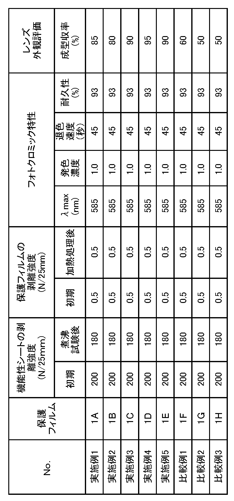
上記実施例1~5から明らかなように、フィルム厚み方向の長さdが、保護フィルムの厚みtに対して1.0tより大きく、かつ、2.0t未満の光学的不純物微粒子を、100cm2あたり10個以下含有する保護フィルムを用いた場合、最終的に得られるレンズの外観が良好であり、優れた成型収率となった。
一方、比較例1~3に示すように、フィルム厚み方向の長さdが、保護フィルムの厚みtに対して2.0tより小さい光学的不純物微粒子を、100cm2あたり11個以上含有する保護フィルムを用いた場合、または長さdが2.0t以上である光学的不純物微粒子を含有する場合、最終的に得られるレンズの成型収率が悪かった。なお、上記実施例1~5、及び比較例1~3は、熱プレス成型により、光学積層体を球面形状への曲げ加工が実施されている。
<実施例6>
(光学積層体の作成)
表5に示すように、保護フィルム2Aを使用した以外は、実施例1と同様の方法で光学積層体を作製した。
得られた光学積層体において、機能性シートの剥離強度(初期剥離強度及び煮沸試験後剥離強度)、保護フィルムの剥離強度(初期剥離強度及び加熱試験後剥離強度)、フォトクロミック特性(最大吸収波長λmax、発色濃度、退色速度、及び耐久性)を測定し、その結果を表6に示した。
また、この光学積層体の型抜き加工性を評価し、その結果を表6に併せて示した。
(光学積層体の作成)
表5に示すように、保護フィルム2Aを使用した以外は、実施例1と同様の方法で光学積層体を作製した。
得られた光学積層体において、機能性シートの剥離強度(初期剥離強度及び煮沸試験後剥離強度)、保護フィルムの剥離強度(初期剥離強度及び加熱試験後剥離強度)、フォトクロミック特性(最大吸収波長λmax、発色濃度、退色速度、及び耐久性)を測定し、その結果を表6に示した。
また、この光学積層体の型抜き加工性を評価し、その結果を表6に併せて示した。
(光学積層体の2次加工〔減圧吸引加工〕)
実施例1と同様の方法で円板状シート20枚を取得した。得られた円板状シートについて、型抜き加工性(良品取得収率)を評価し、その結果を表6に示した。
実施例1と同様の方法で円板状シート20枚を取得した。得られた円板状シートについて、型抜き加工性(良品取得収率)を評価し、その結果を表6に示した。
上記で得られた円板状シートを用い、実施例1の熱プレス成型とは異なり、減圧吸引加工(熱曲げ加工)により、球面形状への曲げ加工を実施した。
この減圧吸引加工は、直径90mmの凹型の金型を150℃雰囲気中に設置し、凹型の金型の中心部の穴から、真空ポンプにて減圧吸引を行うことにより実施した。加工時間は、1枚当たり約20分間実施し、金型から取り外すことで球面形状に加工された光学積層体を得た。なお、減圧吸引加工前には、光学積層体を真空下、80℃で1時間の予備加熱を実施した。
この減圧吸引加工は、直径90mmの凹型の金型を150℃雰囲気中に設置し、凹型の金型の中心部の穴から、真空ポンプにて減圧吸引を行うことにより実施した。加工時間は、1枚当たり約20分間実施し、金型から取り外すことで球面形状に加工された光学積層体を得た。なお、減圧吸引加工前には、光学積層体を真空下、80℃で1時間の予備加熱を実施した。
得られた球面形状を有する光学積層体を用い、実施例1と同様な方法でプラスチックレンズを製造し、レンズの外観評価(レンズ成型収率、不良1、不良2、不良3)を行い、その結果を表6に示した。
<実施例7~22>
表5に示す保護フィルムを使用し、実施例6と同様の方法で光学積層体、さらにはレンズを作製し、実施例6と同様の評価を行い、その結果を表6に示した。
表5に示す保護フィルムを使用し、実施例6と同様の方法で光学積層体、さらにはレンズを作製し、実施例6と同様の評価を行い、その結果を表6に示した。
<実施例23>
保護フィルム2Aを使用し、光学機能層に相当する機能性シートとしてポリビニルアルコール製の偏光フィルムを用いた以外は、実施例6と同様の方法で光学積層体及びレンズを作製し、実施例6と同様の評価を行い、その結果を表6に示した。
保護フィルム2Aを使用し、光学機能層に相当する機能性シートとしてポリビニルアルコール製の偏光フィルムを用いた以外は、実施例6と同様の方法で光学積層体及びレンズを作製し、実施例6と同様の評価を行い、その結果を表6に示した。
<比較例4>
保護フィルム2Aをポリエチレン系粘着剤を用いてポリカーボネートシートに貼り付けた以外は、実施例6と同様の方法で光学積層体及びレンズを作製し、実施例6と同様の評価を行い、その結果を表6に示した。
保護フィルム2Aをポリエチレン系粘着剤を用いてポリカーボネートシートに貼り付けた以外は、実施例6と同様の方法で光学積層体及びレンズを作製し、実施例6と同様の評価を行い、その結果を表6に示した。

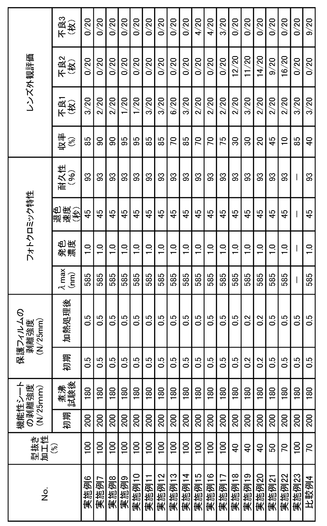
上記実施例6~14から明らかなように、融点が100~125℃の低融点層、及び融点が150~175℃の高融点層からなる保護フィルムを用いた場合、最終的に得られるレンズの外観は、レンズ表面の凹凸に関する不良(不良1)だけでなく、熱曲げ加工における形状不良(不良2)や糊残りに起因する不良(不良3)もなく、極めて優れた成型収率となった。
一方、実施例15~23に示すように、低融点層の融点が100~125℃の範囲外の場合、低融点層に粘着性付与成分が配合されている場合、高融点層の融点が150~175℃の範囲外の場合には、最終的に得られるレンズは、レンズ表面の凹凸に関する不良(不良1)には優れているものの、前記熱曲げ加工における形状不良(不良2)や糊残りに起因する不良(不良3)は劣るものになり、その成型収率は低下した。
さらに、比較例4に示されているように、保護フィルムが粘着剤によりポリカーボネートシートに貼り付けられている場合には、糊残りに起因する不良3が著しく悪いものであった。
さらに、比較例4に示されているように、保護フィルムが粘着剤によりポリカーボネートシートに貼り付けられている場合には、糊残りに起因する不良3が著しく悪いものであった。
1:光学積層体
3:透明基材
5:光学機能層
7:接着層
9:保護フィルム
9a:低融点層
9b:高融点層
15:光学的不純物粒子
3:透明基材
5:光学機能層
7:接着層
9:保護フィルム
9a:低融点層
9b:高融点層
15:光学的不純物粒子
Claims (10)
- 1対の透明基材の間に、光学機能層がサンドイッチされた基本層構造を有しており、少なくとも一方の透明基材の表面に保護フィルムが直接積層されている光学積層体において、
前記保護フィルムには、光学的不純物粒子が不可避的に含まれているが、下記条件式:
1.0t<d<2.0t
式中、
tは前記保護フィルムの厚みであり、
dは前記不純物粒子のフィルム厚み方向の長さである、
を満足する粗大な光学的不純物粒子の数が100cm2あたり、10個以下に抑制されていることを特徴とする光学積層体。 - 前記光学機能層は、光学機能性材料とウレタン樹脂とを含んでなる請求項1に記載の光学積層体。
- 前記光学機能性材料が、フォトクロミック化合物である請求項2に記載の光学積層体。
- 前記保護フィルムが、オレフィン系樹脂製である請求項1に記載の光学積層体。
- 前記保護フィルムの厚みが10~150μmの範囲にある請求項4に記載の光学積層体。
- 前記保護フィルムが、融点が100~125℃の範囲にある低融点層と、融点が150~175℃の範囲にある高融点層とを含んでおり、該低融点層が、前記透明基材の表面に密着している請求項4に記載の光学積層体。
- 前記低融点層の融点が、123℃以下である請求項6に記載の光学積層体。
- 請求項1に記載の光学積層体からなる型抜き加工品。
- 請求項1に記載の光学積層体からなる熱曲げ加工品。
- 1対の透明基材の間に、光学機能層がサンドイッチされた基本層構造を有しており、少なくとも一方の透明基材の表面に保護フィルムが直接積層されている光学積層体において、前記保護フィルムが、融点が100~125℃の範囲にある低融点層と、融点が150~175℃の範囲にある高融点層とを含んでおり、該低融点層が、前記透明基材の表面に密着していることを特徴とする光学積層体。
Applications Claiming Priority (4)
| Application Number | Priority Date | Filing Date | Title |
|---|---|---|---|
| JP2015088863A JP2016206463A (ja) | 2015-04-24 | 2015-04-24 | フォトクロミック積層体 |
| JP2015-088863 | 2015-04-24 | ||
| JP2015213764 | 2015-10-30 | ||
| JP2015-213764 | 2015-10-30 |
Publications (1)
| Publication Number | Publication Date |
|---|---|
| WO2016171223A1 true WO2016171223A1 (ja) | 2016-10-27 |
Family
ID=57143976
Family Applications (1)
| Application Number | Title | Priority Date | Filing Date |
|---|---|---|---|
| PCT/JP2016/062670 Ceased WO2016171223A1 (ja) | 2015-04-24 | 2016-04-21 | 光学積層体 |
Country Status (2)
| Country | Link |
|---|---|
| TW (1) | TW201707954A (ja) |
| WO (1) | WO2016171223A1 (ja) |
Cited By (4)
| Publication number | Priority date | Publication date | Assignee | Title |
|---|---|---|---|---|
| KR20170086033A (ko) * | 2014-11-21 | 2017-07-25 | 미츠비시 가스 가가쿠 가부시키가이샤 | 보호 필름 부착 기능성 시트 |
| WO2018199173A1 (ja) * | 2017-04-25 | 2018-11-01 | 住友ベークライト株式会社 | 保護フィルム |
| WO2020040189A1 (ja) * | 2018-08-21 | 2020-02-27 | 住友ベークライト株式会社 | 保護フィルム |
| JP2020173284A (ja) * | 2019-04-05 | 2020-10-22 | 住友ベークライト株式会社 | 光学部品の製造方法 |
Citations (4)
| Publication number | Priority date | Publication date | Assignee | Title |
|---|---|---|---|---|
| JP2003145616A (ja) * | 2001-11-12 | 2003-05-20 | Mitsubishi Gas Chem Co Inc | ポリカーボネート板の保護フィルム |
| JP2008055691A (ja) * | 2006-08-30 | 2008-03-13 | Jsr Corp | 光学フィルムロール、およびその製造方法 |
| JP2011110879A (ja) * | 2009-11-30 | 2011-06-09 | Sumitomo Bakelite Co Ltd | ポリカーボネート樹脂成形体の製造方法、ポリカーボネート樹脂成形体、防眩製品および防護製品 |
| JP2014113761A (ja) * | 2012-12-11 | 2014-06-26 | Tokuyama Corp | 積層シートの製造方法 |
-
2016
- 2016-04-21 WO PCT/JP2016/062670 patent/WO2016171223A1/ja not_active Ceased
- 2016-04-22 TW TW105112544A patent/TW201707954A/zh unknown
Patent Citations (4)
| Publication number | Priority date | Publication date | Assignee | Title |
|---|---|---|---|---|
| JP2003145616A (ja) * | 2001-11-12 | 2003-05-20 | Mitsubishi Gas Chem Co Inc | ポリカーボネート板の保護フィルム |
| JP2008055691A (ja) * | 2006-08-30 | 2008-03-13 | Jsr Corp | 光学フィルムロール、およびその製造方法 |
| JP2011110879A (ja) * | 2009-11-30 | 2011-06-09 | Sumitomo Bakelite Co Ltd | ポリカーボネート樹脂成形体の製造方法、ポリカーボネート樹脂成形体、防眩製品および防護製品 |
| JP2014113761A (ja) * | 2012-12-11 | 2014-06-26 | Tokuyama Corp | 積層シートの製造方法 |
Cited By (13)
| Publication number | Priority date | Publication date | Assignee | Title |
|---|---|---|---|---|
| KR102404305B1 (ko) | 2014-11-21 | 2022-05-31 | 미츠비시 가스 가가쿠 가부시키가이샤 | 보호 필름 부착 기능성 시트 |
| JPWO2016080445A1 (ja) * | 2014-11-21 | 2017-11-09 | 三菱瓦斯化学株式会社 | 保護フィルム付き機能性シート |
| EP3222420A4 (en) * | 2014-11-21 | 2018-04-25 | Mitsubishi Gas Chemical Company, Inc. | Functional sheet with protective film |
| KR20170086033A (ko) * | 2014-11-21 | 2017-07-25 | 미츠비시 가스 가가쿠 가부시키가이샤 | 보호 필름 부착 기능성 시트 |
| WO2018199173A1 (ja) * | 2017-04-25 | 2018-11-01 | 住友ベークライト株式会社 | 保護フィルム |
| CN110546002A (zh) * | 2017-04-25 | 2019-12-06 | 住友电木株式会社 | 保护膜 |
| JPWO2018199173A1 (ja) * | 2017-04-25 | 2019-06-27 | 住友ベークライト株式会社 | 保護フィルム |
| US11396615B2 (en) | 2017-04-25 | 2022-07-26 | Sumitomo Bakelite Co., Ltd. | Protective film |
| WO2020040189A1 (ja) * | 2018-08-21 | 2020-02-27 | 住友ベークライト株式会社 | 保護フィルム |
| JP2020037184A (ja) * | 2018-08-21 | 2020-03-12 | 住友ベークライト株式会社 | 保護フィルム |
| US11584870B2 (en) | 2018-08-21 | 2023-02-21 | Sumitomo Bakelite Co., Ltd. | Protective film |
| JP2020173284A (ja) * | 2019-04-05 | 2020-10-22 | 住友ベークライト株式会社 | 光学部品の製造方法 |
| JP2023105170A (ja) * | 2019-04-05 | 2023-07-28 | 住友ベークライト株式会社 | 光学部品の製造方法 |
Also Published As
| Publication number | Publication date |
|---|---|
| TW201707954A (zh) | 2017-03-01 |
Similar Documents
| Publication | Publication Date | Title |
|---|---|---|
| JP5757954B2 (ja) | 積層レンズのための三層接着剤系及びその適用法 | |
| EP0299509B1 (en) | Curved polarizing sheet protected with polycarbonate and process for producing the same | |
| TWI621527B (zh) | Functional film with protective film | |
| JP4987297B2 (ja) | 機能性光学レンズ及びその製造方法 | |
| US20040125337A1 (en) | Laminated functional wafer for plastic optical elements | |
| KR20170116236A (ko) | 기능성 시트 및 그것을 이용한 렌즈 | |
| KR20190005836A (ko) | 유기 el 표시 장치용 광학 필름, 유기 el 표시 장치용 편광 필름, 유기 el 표시 장치용 점착제층 구비 편광 필름, 및 유기 el 표시 장치 | |
| WO2002099513A1 (en) | Plastic molded product having photochromic characteristics and/or polarizing characteristics | |
| KR102134802B1 (ko) | 편광성 구조물용 폴리우레탄계 접착제 및 편광 렌즈 | |
| US10564325B2 (en) | Protective film-attached functional sheet | |
| JP2009294445A (ja) | 偏光性積層体とその製造方法 | |
| WO2016171223A1 (ja) | 光学積層体 | |
| JP2020052406A (ja) | 機能性シート | |
| KR20160117435A (ko) | 글리옥살 접착 시스템을 포함하는 편광 구조 및 이를 포함하는 편광 렌즈 | |
| JP2014206732A (ja) | 偏光板の製造方法 | |
| US20160216425A1 (en) | Functionalised layered structure | |
| JP2011110879A (ja) | ポリカーボネート樹脂成形体の製造方法、ポリカーボネート樹脂成形体、防眩製品および防護製品 | |
| JP2011085900A (ja) | 偏光板、偏光レンズおよび防眩製品 | |
| CN101726764A (zh) | 一种偏光镜片及其制造方法 | |
| JP2018066772A (ja) | 光学積層体 | |
| JP7118876B2 (ja) | 積層体、該積層体からなる光学基材、および該光学基材を備えた光学物品 | |
| KR101258553B1 (ko) | 편광자 보호 필름, 편광판 및 액정 표시 소자 | |
| JP2025131799A (ja) | 機能性ラミネートの調製方法 | |
| JP2017081160A (ja) | 機能性シート | |
| JP2010286827A (ja) | 偏光子保護フィルム、偏光板及び液晶表示素子 |
Legal Events
| Date | Code | Title | Description |
|---|---|---|---|
| 121 | Ep: the epo has been informed by wipo that ep was designated in this application |
Ref document number: 16783244 Country of ref document: EP Kind code of ref document: A1 |
|
| NENP | Non-entry into the national phase |
Ref country code: DE |
|
| 122 | Ep: pct application non-entry in european phase |
Ref document number: 16783244 Country of ref document: EP Kind code of ref document: A1 |