WO2016171205A1 - アウターローター型回転電機 - Google Patents
アウターローター型回転電機 Download PDFInfo
- Publication number
- WO2016171205A1 WO2016171205A1 PCT/JP2016/062616 JP2016062616W WO2016171205A1 WO 2016171205 A1 WO2016171205 A1 WO 2016171205A1 JP 2016062616 W JP2016062616 W JP 2016062616W WO 2016171205 A1 WO2016171205 A1 WO 2016171205A1
- Authority
- WO
- WIPO (PCT)
- Prior art keywords
- insulator
- terminal unit
- electrical machine
- rotating electrical
- type rotating
- Prior art date
- Legal status (The legal status is an assumption and is not a legal conclusion. Google has not performed a legal analysis and makes no representation as to the accuracy of the status listed.)
- Ceased
Links
Images




Classifications
-
- H—ELECTRICITY
- H02—GENERATION; CONVERSION OR DISTRIBUTION OF ELECTRIC POWER
- H02K—DYNAMO-ELECTRIC MACHINES
- H02K3/00—Details of windings
- H02K3/46—Fastening of windings on the stator or rotor structure
Definitions
- the present invention relates to an outer rotor type rotating electrical machine.
- This application claims priority based on Japanese Patent Application No. 2015-087051 for which it applied on April 21, 2015, and uses the content here.
- a magnet generator having a magnet is widely used as a generator for charging a battery and supplying electric power to electrical components.
- This type of magnet generator includes a rotor connected to a crankshaft of an engine of a motorcycle and a stator fixed to an engine case, and the stator is disposed inside the rotor.
- the rotor includes a substantially bowl-shaped flywheel having a plurality of magnets on the inner periphery.
- the stator includes a stator core around which a coil is wound.
- a resin insulator is attached to the stator core.
- the insulator is provided with a neutral point terminal of metal (for example, brass).
- the stator core is wound with a U-phase, V-phase, and W-phase coil on an insulator.
- the U-phase, V-phase, and W-phase coils are star-connected through neutral point terminals (see, for example, Patent Document 1).
- the neutral point terminal is press-fitted and fixed to the insulator.
- the U-phase, V-phase, and W-phase coils are connected to the neutral point terminal by solder.
- the insulator may be deformed by heat generated during soldering. If the insulator is deformed, the neutral point terminal may fall off from the insulator.
- the purpose of the embodiment of the present invention is to prevent the neutral point terminal from falling off the insulator even when the insulator is deformed by heat generated during soldering, etc.
- the object is to provide a rotary electric machine.
- the neutral point terminal is sandwiched between the insulator and the stator core via the fixing member. For this reason, even if the insulator is deformed by heat generated when the U-phase, V-phase, and W-phase coils are soldered to the neutral point terminal, the neutral point terminal is dropped from the insulator and the coil is disconnected. There is no.
- One aspect of the present invention is an outer rotor type rotating electrical machine including a stator and a rotor that rotates around the stator.
- the stator includes a stator core made of a magnetic material, an insulator attached to the stator core, and
- the rotor includes a coil wound around a stator core via an insulator, and a terminal unit having a terminal plate to which the coil is connected.
- the rotor rotates around the stator, and the inner peripheral surface of the flywheel.
- the terminal unit has an insulating fixing member to which the terminal plate is fixed, and the insulator has a terminal unit holding portion in which a storage chamber for storing the terminal unit is formed.
- the terminal unit is housed in the terminal unit holding portion of the insulator, and the fixing member is formed by the insulator and the stator core.
- It is outer rotor type rotating electrical machine, characterized in that the lifting.
- the first end of the fixing member of the terminal unit may contact the wall of the storage chamber of the terminal unit holding portion of the insulator, and the second end of the fixing member of the terminal unit. May contact the side wall of the stator core.
- the wall portion of the storage chamber of the terminal unit holding portion of the insulator may be formed with a slit portion through which the terminal plate of the terminal unit is inserted, and protrudes from the insulator through the slit.
- a coil may be connected to the coil holding portion of the terminal board.
- a terminal plate may be press-fitted and fixed to the fixing member.
- an outer rotor type rotating electrical machine in another aspect of the present invention, includes a stator and a rotor.
- the stator includes a stator core made of a magnetic material, an insulator attached to the stator core, a coil wound around the stator core, and a terminal unit having a terminal plate to which the coil is connected.
- the rotor includes a flywheel arranged to rotate with respect to the stator, and a plurality of magnets fixed to the flywheel.
- the terminal unit has an insulating fixing member to which the terminal plate is attached.
- the insulator has a wall arranged to cover at least a part of the fixing member.
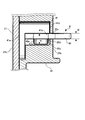
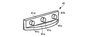
- FIG. 2 is a cross-sectional view taken along the line AA in FIG. It is the B section enlarged view of FIG. It is a perspective view of a fixing member. It is a perspective view of a neutral point terminal. It is a perspective view of a neutral point terminal unit.
- a magnet generator (outer rotor type rotating electrical machine) 1 for a motorcycle will be described with reference to FIGS. 1 and 2.
- the magnet generator 1 is used as, for example, a magnet generator in a motorcycle.
- the magnet generator 1 has a stator 2 that is fixed to an engine case (not shown) and a rotor 3 that is fixed to the tip of an engine crankshaft (not shown).
- the rotor 3 rotates around the stator 2 as the crankshaft rotates.
- the rotor 3 is arranged to rotate with respect to the stator 2.
- the rotor 3 has a substantially bowl-shaped flywheel 31 and a boss 32 fixed at the radial center of the bottom surface of the flywheel 31.
- a plurality of magnets 33 are arranged at equal intervals in the circumferential direction.
- the boss 32 has a cylindrical tube portion 32a and a substantially disc-shaped flange portion 32b.
- the flange portion 32b is integrally formed with the cylindrical portion 32a.
- the flange portion 32 b is fastened and fixed to the bottom surface of the flywheel 31 by a plurality of rivets 100.
- a crankshaft (not shown) is fixed to the cylindrical portion 32 a of the boss 32.
- a resin ring-shaped magnet case 34 is installed inside the bottom 31a of the flywheel 31.
- a magnet 33 is placed on the magnet case 34.
- a magnet holder 35 is placed on one end of the magnet 33.
- the magnet 33 is pressed against the inner peripheral surface of the flywheel 31 by bending the magnet holder 35.
- the magnet 33 is substantially fixed to the inner peripheral surface of the flywheel 31.
- the magnet holder 35 is fixed by curling the opening peripheral edge 31b of the flywheel 31.
- the stator 2 has a stator core 21 and an insulator 22 attached to the stator core 21.
- a coil 23 is wound around the stator core 21 via an insulator 22.
- the stator core 21 is formed by laminating magnetic material plates at least in the axial direction.
- a hole (boss hole) 21e is formed in the center in the radial direction.
- An engine crankshaft (not shown) is inserted through the hole 21e.
- the crankshaft and the rotor 3 are connected to each other through a cylindrical portion 32a of the boss 32.
- the stator core 21 has an annular ring portion 21b and a teeth portion 21c extending radially outward from the annular portion 21b.
- a plurality of bolt holes 21 d are formed in the annular portion 21 b of the stator core 21.
- the stator 2 is fastened and fixed to the engine case by a bolt 101 inserted into the bolt hole 21d.
- the insulator 22 attached to the stator core 21 has a terminal unit holding part (holding part) 22b and a storage chamber 22c.
- the terminal unit holding part 22b is formed with a slit part (slit) 22a.
- a part of the neutral point terminal unit (terminal unit) 4 is accommodated in the accommodation chamber 22c.
- another part of the neutral point terminal unit 4 is disposed through the slit portion 22a.
- the neutral point terminal unit 4 is press-fitted and fixed to the terminal unit holding part 22b via the slit part 22a.
- a part of the neutral point terminal unit 4 is disposed so as to protrude from the outer surface of the insulator 22 (protruding portion).
- One end of the coil 23 of each phase wound is connected to the neutral point terminal unit 4 press-fitted and fixed to the terminal unit holding portion 22b.
- the coil 23 is composed of a U-phase, V-phase, and W-phase coil 23, and each phase coil 23 is wound around a tooth portion 21c.
- One end of the coil 23 of each phase is fixed to the coil holding portion 42b of the neutral point terminal 42 by, for example, solder, and a star connection is configured.
- the other end of each phase coil 23 is electrically and mechanically joined to the corresponding phase lead wire 102.
- the neutral point terminal unit 4 will be described with reference to FIGS.
- the neutral point terminal unit 4 includes an insulating (for example, resin) fixing member 41 and a conductive neutral point terminal (terminal, terminal plate) 42.
- the insulator 22 has a wall portion (wall) 22 b that is arranged so as to cover at least a part of the fixing member 41.
- a part of the neutral point terminal unit 4 (a part of the fixing member 41 and the neutral point terminal 42) is accommodated in an accommodation chamber 22c formed in the terminal holding portion 22b of the insulator 22.
- the wall portion (wall) 22b is provided such that an axial gap (storage chamber 22c) is formed between the stator core 21 and the wall portion 22b.
- the fixing member 41 is disposed in the gap (the storage chamber 22c).
- another part of the neutral point terminal unit 4 (a part of the neutral point terminal 42) is inserted into the slit part (slit) 22a and disposed through the slit part 22a.
- the neutral point terminal unit 4 is press-fitted and fixed to the terminal unit holding portion 22b of the insulator 22 through the slit portion 22a.
- the fixing member 41 is L-shaped in cross-section and has a lower end (second end) 41a and a wall 41b.
- a plurality of protrusions 41 c are formed on the wall 41 b of the fixing member 41 at regular intervals, for example.
- the neutral point terminal 42 is formed in a plate shape (for example, a substantially flat plate shape).
- the neutral point terminal 42 has a flat plate portion 42d and a coil holding portion 42b.
- a through hole 42a into which the protrusion 41c of the fixing member 41 is press-fitted is formed in the flat plate portion 42d.
- Side portions 42c are linearly formed on both side surfaces of the flat plate portion 42d. Since the straight side surface portion 42c is formed on both side surfaces of the flat plate portion 42d, when the neutral point terminal 42 is manufactured by press working, the side surface portion 42c and the second side surface portion 42c of the first neutral point terminal 42 are formed.
- the neutral point terminal 42 can be brought close to the side surface 42c, and the yield is improved.
- the neutral point terminal 42 is attached (fixed) to the fixing member 41.
- the protrusion 41 c of the fixing member 41 is press-fitted into the through hole 42 a of the neutral point terminal 42, so that the neutral point terminal 42 is integrated with the fixing member 41.
- the neutral point terminal unit 4 is accommodated in the accommodation chamber 22 c and press-fitted into the insulator 22, the upper end portion (first end portion) 41 d of the fixing member 41 comes into contact with the wall portion (wall) 22 b of the insulator 22. .
- the lower end portion 41 a of the fixing member 41 comes into contact with the annular portion 21 b of the stator core 21.
- the coil 23 is wound around the tooth portion 21 c of the stator core 21 via the insulator 22.
- the upper end portion 41 d of the fixing member 41 is in close contact with the insulator 22, and the lower end portion 41 a of the fixing member 41 is in close contact with the annular portion 21 b of the stator core 21.
- the neutral point terminal unit 4 is sandwiched between the insulator 22 (wall portion 22b) and the stator core 21.
- the neutral point terminal 42 is held by the terminal unit holding portion 22 b of the insulator 22. At least a part of the fixing member 41 is covered with a wall portion (wall) 22 b of the insulator 22.
- the width W of the slit portion 22 a is narrower than the height H of the protrusion 41 c of the fixing member 41. Even when the insulator 22 is deformed by heat generated during soldering, the neutral point terminal unit 4 does not fall out of the insulator 22 through the slit portion 22a of the insulator 22.
- the insulator 22 is applied to a two-wheeled motor magnet generator.
- the insulator 22 may be applied to a generator or an electric motor for other purposes.
- the neutral point terminal unit 4 is formed by forming the protrusion 41c and the bottom 31a on the insulating (for example, resin) fixing member 41.
- the neutral point terminal 42 may be indirectly held by the insulator 22 and is not limited to this.
- the neutral point terminal unit 4 may be formed by insert molding the neutral point terminal 42.
Landscapes
- Engineering & Computer Science (AREA)
- Power Engineering (AREA)
- Insulation, Fastening Of Motor, Generator Windings (AREA)
Abstract
Description
本願は、2015年4月21日に出願された、特願2015-087051号に基づき優先権を主張し、その内容をここに援用する。
2 固定子
3 回転子
4 中性点端子ユニット
21 ステータコア
21a ボス孔
21b 円環部
21c ティース部
21d ボルト孔
21e ボス孔
22 インシュレータ
22a スリット部
22b 端子ユニット保持部
22c 収容室
22d 壁部
23 コイル
31 フライホイール
31a 底部
31b 開口周縁部
32 ボス
33 マグネット
33a 上端部
34 マグネットケース
35 マグネットホルダー
41 固定部材
41a 下端部(第2端部)
41b 壁部
41c 突起
41d 上端部(第1端部)
42 中性点端子
42a 貫通孔
42b コイル保持部
42c 側面部
100 リベット
101 ボルト
102 リード線
Claims (9)
- 固定子と、前記固定子の周囲を回転する回転子とを備えたアウターローター型回転電機において、
前記固定子は、磁性材料からなるステータコアと、前記ステータコアに装着されたインシュレータと、前記インシュレータを介して前記ステータコアに巻装されたコイルと、前記コイルが接続された端子板を有する端子ユニットとを有し、
前記回転子は、前記固定子の周りを回転するフライホイールと、前記フライホイールの内周面に固定された複数のマグネットとを有し、
前記端子ユニットは、前記端子板が固定される絶縁性の固定部材を備え、
前記インシュレータは、前記端子ユニットを収納する収納室が形成された端子ユニット保持部を備え、
前記端子ユニットは、前記インシュレータの前記端子ユニット保持部に収納され、
前記固定部材が前記インシュレータと前記ステータコアとによって挟持されている、ことを特徴とするアウターローター型回転電機。 - 請求項1に記載されたアウターローター型回転電機において、
前記端子ユニットの固定部材の第1端部は、前記インシュレータの前記端子ユニット保持部の収納室の壁部に当接し、前記端子ユニットの固定部材の第2端部は、前記ステータコアの側壁部に当接している、ことを特徴とするアウターローター型回転電機。 - 請求項2に記載されたアウターローター型回転電機において、
前記インシュレータの前記端子ユニット保持部の収納室の壁部には、前記端子ユニットの端子板が挿通されるスリット部が形成され、前記スリットを通って前記インシュレータから突出した前記端子板のコイル保持部に前記コイルが接続されている、ことを特徴とするアウターローター型回転電機。 - 請求項1から請求項3のうち、いずれか1項に記載されたアウターローター型回転電機において、
前記固定部材には、前記端子板が圧入固定されている、ことを特徴とするアウターローター型回転電機。 - 固定子と、
回転子と、を備え、
前記固定子は、磁性材料からなるステータコアと、前記ステータコアに装着されたインシュレータと、前記ステータコアに巻装されたコイルと、前記コイルが接続された端子板を有する端子ユニットと、を有し、
前記回転子は、前記固定子に対して回転するように配されるフライホイールと、前記フライホイールに固定された複数のマグネットと、を有し、
前記端子ユニットは、前記端子板が取り付けられる絶縁性の固定部材を有し、
前記インシュレータは、前記固定部材の少なくとも一部を覆うように配される壁を有する、アウターローター型回転電機。 - 前記壁は、前記ステータコアと前記壁との間に軸方向のギャップが形成されるように設けられ、
前記固定部材の少なくとも一部が前記ギャップに配置される、請求項5に記載のアウターローター型回転電機。 - 前記壁は、前記固定部材に当接するように配置される、請求項5又は6に記載のアウターローター型回転電機。
- 前記壁は、前記端子板が挿入されるスリットを有する、請求項5から7のいずれか一項に記載のアウターローター型回転電機。
- 前記固定部材には、前記端子板が圧入固定されている、、請求項5から8のいずれ一項に記載のアウターローター型回転電機。
Priority Applications (3)
| Application Number | Priority Date | Filing Date | Title |
|---|---|---|---|
| BR112017022426A BR112017022426B1 (pt) | 2015-04-21 | 2016-04-21 | máquina elétrica rotativa do tipo de rotor externo |
| CN201680018337.2A CN107710559B (zh) | 2015-04-21 | 2016-04-21 | 外转子型旋转电机 |
| JP2017514180A JP6343394B2 (ja) | 2015-04-21 | 2016-04-21 | アウターローター型回転電機 |
Applications Claiming Priority (2)
| Application Number | Priority Date | Filing Date | Title |
|---|---|---|---|
| JP2015-087051 | 2015-04-21 | ||
| JP2015087051 | 2015-04-21 |
Publications (1)
| Publication Number | Publication Date |
|---|---|
| WO2016171205A1 true WO2016171205A1 (ja) | 2016-10-27 |
Family
ID=57143225
Family Applications (1)
| Application Number | Title | Priority Date | Filing Date |
|---|---|---|---|
| PCT/JP2016/062616 Ceased WO2016171205A1 (ja) | 2015-04-21 | 2016-04-21 | アウターローター型回転電機 |
Country Status (4)
| Country | Link |
|---|---|
| JP (1) | JP6343394B2 (ja) |
| CN (1) | CN107710559B (ja) |
| BR (1) | BR112017022426B1 (ja) |
| WO (1) | WO2016171205A1 (ja) |
Cited By (1)
| Publication number | Priority date | Publication date | Assignee | Title |
|---|---|---|---|---|
| WO2024185370A1 (ja) * | 2023-03-03 | 2024-09-12 | 株式会社デンソートリム | 回転電機、回転電機用ステータ、回転電機用ステータの中性点ターミナル、及び回転電機用ステータの製造方法 |
Families Citing this family (1)
| Publication number | Priority date | Publication date | Assignee | Title |
|---|---|---|---|---|
| JP6729651B2 (ja) | 2018-09-18 | 2020-07-22 | 株式会社富士通ゼネラル | モータ及び圧縮機 |
Citations (2)
| Publication number | Priority date | Publication date | Assignee | Title |
|---|---|---|---|---|
| JPS5947954A (ja) * | 1982-09-10 | 1984-03-17 | Honda Motor Co Ltd | フライホイール式磁石発電機の製造方法 |
| JP2002315252A (ja) * | 2001-04-12 | 2002-10-25 | Moric Co Ltd | 回転電気機器のステータボビン |
Family Cites Families (1)
| Publication number | Priority date | Publication date | Assignee | Title |
|---|---|---|---|---|
| JP2013042633A (ja) * | 2011-08-19 | 2013-02-28 | Nippon Densan Corp | モータ |
-
2016
- 2016-04-21 BR BR112017022426A patent/BR112017022426B1/pt active IP Right Grant
- 2016-04-21 JP JP2017514180A patent/JP6343394B2/ja active Active
- 2016-04-21 WO PCT/JP2016/062616 patent/WO2016171205A1/ja not_active Ceased
- 2016-04-21 CN CN201680018337.2A patent/CN107710559B/zh active Active
Patent Citations (2)
| Publication number | Priority date | Publication date | Assignee | Title |
|---|---|---|---|---|
| JPS5947954A (ja) * | 1982-09-10 | 1984-03-17 | Honda Motor Co Ltd | フライホイール式磁石発電機の製造方法 |
| JP2002315252A (ja) * | 2001-04-12 | 2002-10-25 | Moric Co Ltd | 回転電気機器のステータボビン |
Cited By (1)
| Publication number | Priority date | Publication date | Assignee | Title |
|---|---|---|---|---|
| WO2024185370A1 (ja) * | 2023-03-03 | 2024-09-12 | 株式会社デンソートリム | 回転電機、回転電機用ステータ、回転電機用ステータの中性点ターミナル、及び回転電機用ステータの製造方法 |
Also Published As
| Publication number | Publication date |
|---|---|
| CN107710559B (zh) | 2019-09-06 |
| BR112017022426B1 (pt) | 2019-10-22 |
| JP6343394B2 (ja) | 2018-06-20 |
| CN107710559A (zh) | 2018-02-16 |
| JPWO2016171205A1 (ja) | 2017-11-09 |
| BR112017022426A2 (ja) | 2018-07-10 |
Similar Documents
| Publication | Publication Date | Title |
|---|---|---|
| CN107210660B (zh) | 内燃机用旋转电机及其定子 | |
| CN104541437B (zh) | 定子单元以及马达 | |
| JP6070665B2 (ja) | 回転電機ステータ | |
| JP6125385B2 (ja) | ステータ用端子 | |
| JP6353722B2 (ja) | バスバーユニット及びこれを備えた回転電機 | |
| JP2018191403A (ja) | ステータおよびレゾルバ | |
| JP2009142031A (ja) | 回転電機用ステータ | |
| JP2016178783A (ja) | ステータ、回転電機、車両、ステータの製造方法 | |
| JP2009261094A (ja) | 回転電機の集配電構造 | |
| JP2019140871A (ja) | レゾルバのステータ構造およびレゾルバ | |
| US9537365B2 (en) | Magnet-type generator | |
| JP2016144394A (ja) | 電気モータ | |
| JP2017189095A (ja) | ステータ構造およびレゾルバ | |
| US10958124B2 (en) | Motor | |
| JP2018148667A (ja) | 回転電機 | |
| JP6343394B2 (ja) | アウターローター型回転電機 | |
| CN108028558A (zh) | 旋转电机以及旋转电机的制造方法 | |
| JP2019193472A (ja) | ステータ構造およびレゾルバ | |
| JP6041670B2 (ja) | 回転機 | |
| JP6853149B2 (ja) | ステータ構造およびレゾルバ | |
| JP2014233124A (ja) | 回転電気機械のステーターカバー | |
| JP7218854B2 (ja) | 回転電機、インシュレータ、およびそのアセンブリ方法 | |
| JP5781239B2 (ja) | 回転電機の回転子およびその製造方法 | |
| JP5937458B2 (ja) | ステータ、ステータを用いたアウターロータ型回転電機、および、ステータの製造方法 | |
| JP6899679B2 (ja) | コンデンサー搭載電動機 |
Legal Events
| Date | Code | Title | Description |
|---|---|---|---|
| 121 | Ep: the epo has been informed by wipo that ep was designated in this application |
Ref document number: 16783226 Country of ref document: EP Kind code of ref document: A1 |
|
| DPE1 | Request for preliminary examination filed after expiration of 19th month from priority date (pct application filed from 20040101) | ||
| ENP | Entry into the national phase |
Ref document number: 2017514180 Country of ref document: JP Kind code of ref document: A |
|
| NENP | Non-entry into the national phase |
Ref country code: DE |
|
| REG | Reference to national code |
Ref country code: BR Ref legal event code: B01A Ref document number: 112017022426 Country of ref document: BR |
|
| 122 | Ep: pct application non-entry in european phase |
Ref document number: 16783226 Country of ref document: EP Kind code of ref document: A1 |
|
| ENP | Entry into the national phase |
Ref document number: 112017022426 Country of ref document: BR Kind code of ref document: A2 Effective date: 20171018 |