WO2016171059A1 - 位置検出装置及び位置検出装置の使用構造 - Google Patents
位置検出装置及び位置検出装置の使用構造 Download PDFInfo
- Publication number
- WO2016171059A1 WO2016171059A1 PCT/JP2016/061940 JP2016061940W WO2016171059A1 WO 2016171059 A1 WO2016171059 A1 WO 2016171059A1 JP 2016061940 W JP2016061940 W JP 2016061940W WO 2016171059 A1 WO2016171059 A1 WO 2016171059A1
- Authority
- WO
- WIPO (PCT)
- Prior art keywords
- magnet
- detection
- magnetic field
- bias magnet
- detection device
- Prior art date
- Legal status (The legal status is an assumption and is not a legal conclusion. Google has not performed a legal analysis and makes no representation as to the accuracy of the status listed.)
- Ceased
Links
Images




Classifications
-
- G—PHYSICS
- G01—MEASURING; TESTING
- G01D—MEASURING NOT SPECIALLY ADAPTED FOR A SPECIFIC VARIABLE; ARRANGEMENTS FOR MEASURING TWO OR MORE VARIABLES NOT COVERED IN A SINGLE OTHER SUBCLASS; TARIFF METERING APPARATUS; MEASURING OR TESTING NOT OTHERWISE PROVIDED FOR
- G01D5/00—Mechanical means for transferring the output of a sensing member; Means for converting the output of a sensing member to another variable where the form or nature of the sensing member does not constrain the means for converting; Transducers not specially adapted for a specific variable
- G01D5/12—Mechanical means for transferring the output of a sensing member; Means for converting the output of a sensing member to another variable where the form or nature of the sensing member does not constrain the means for converting; Transducers not specially adapted for a specific variable using electric or magnetic means
-
- G—PHYSICS
- G01—MEASURING; TESTING
- G01D—MEASURING NOT SPECIALLY ADAPTED FOR A SPECIFIC VARIABLE; ARRANGEMENTS FOR MEASURING TWO OR MORE VARIABLES NOT COVERED IN A SINGLE OTHER SUBCLASS; TARIFF METERING APPARATUS; MEASURING OR TESTING NOT OTHERWISE PROVIDED FOR
- G01D5/00—Mechanical means for transferring the output of a sensing member; Means for converting the output of a sensing member to another variable where the form or nature of the sensing member does not constrain the means for converting; Transducers not specially adapted for a specific variable
- G01D5/12—Mechanical means for transferring the output of a sensing member; Means for converting the output of a sensing member to another variable where the form or nature of the sensing member does not constrain the means for converting; Transducers not specially adapted for a specific variable using electric or magnetic means
- G01D5/14—Mechanical means for transferring the output of a sensing member; Means for converting the output of a sensing member to another variable where the form or nature of the sensing member does not constrain the means for converting; Transducers not specially adapted for a specific variable using electric or magnetic means influencing the magnitude of a current or voltage
- G01D5/142—Mechanical means for transferring the output of a sensing member; Means for converting the output of a sensing member to another variable where the form or nature of the sensing member does not constrain the means for converting; Transducers not specially adapted for a specific variable using electric or magnetic means influencing the magnitude of a current or voltage using Hall-effect devices
- G01D5/147—Mechanical means for transferring the output of a sensing member; Means for converting the output of a sensing member to another variable where the form or nature of the sensing member does not constrain the means for converting; Transducers not specially adapted for a specific variable using electric or magnetic means influencing the magnitude of a current or voltage using Hall-effect devices influenced by the movement of a third element, the position of Hall device and the source of magnetic field being fixed in respect to each other
Definitions
- the present invention relates to a position detection device and a use structure of the position detection device.
- the position detection device described in Patent Literature 1 includes a magnetic member in which N poles and S poles are alternately magnetized, and a magnetoresistive effect element facing the magnetic pole arrangement surface of the magnetic member.
- the magnetoresistive effect element includes a plurality of magnets and is provided on the detection target.
- the magnetoresistive element includes a plurality of magnets.
- the configuration of the object to be detected it may not be possible to secure a region for attaching a plurality of magnets. Therefore, in the conventional position detection apparatus, there are limitations on the applicable detection objects. Also, if the number of magnets is reduced, the effect on the magnetic field is reduced, so that the change in the direction of the magnetic field is reduced. Therefore, when the amount of movement of the detection target is large, it is difficult to capture a change in the direction of the magnetic field depending on the position of the detection target. Therefore, the range in which the position of the detection object can be detected is small.
- An object of one aspect of the present invention is to provide a position detection device capable of detecting the positions of various detection objects in a wide range and a structure for using the position detection device.
- a position detection device is a position detection device that detects the position of a detection target that is a magnetic body, and is generated by a first magnet and a second magnet, and a first magnet and a second magnet.
- a detection element for detecting the direction of the magnetic field wherein the first magnet and the second magnet are arranged with the same polarity facing each other, and the detection object in the facing direction of the first magnet and the second magnet The movement changes the direction of the magnetic field detected by the detection element.
- the first magnet and the second magnet are arranged to face each other with the same polarity.
- the detection element detects the direction at the position of the detection element of the magnetic field that changes due to the movement of the detection object in the facing direction of the two magnets.
- the magnetic field generated by two magnets facing the same pole is established by a delicate balance of the lines of magnetic force generated from each magnet. For this reason, the direction of the magnetic field changes greatly when it receives an external action such as shielding and / or absorption of magnetic field lines. Therefore, the position detection device can detect a change in the direction of the magnetic field accompanying the movement of the detection target at the position of the detection element even when the detection target has a small effect on the magnetic field. Therefore, the position detection device can detect the positions of various detection objects in a wide range.
- the object to be detected may be located in a range between the first magnet and the second magnet when viewed from a direction orthogonal to the facing direction.
- the detection object moves in a range between the first magnet and the second magnet.
- the movement of the detection target effectively acts on the direction of the magnetic field. Therefore, the detection element can detect the change in the direction of the magnetic field more reliably. As a result, the position of the detection object can be detected with high accuracy.
- At least a part of the detection target object may be located between the first magnet and the second magnet.
- the positions of the first magnet and the second magnet can be easily set with respect to the detection target, and the occurrence of a shift in the positions of the detection target, the first magnet, and the second magnet can be suppressed.
- action to the direction of the magnetic field by the movement of a detection target object can be made more exact. Therefore, the detection element can detect the change in the direction of the magnetic field more reliably. As a result, the position of the detection object can be detected with high accuracy.
- the detection element has a magnetic field in a range between the first magnet and the second magnet when viewed from a direction orthogonal to the opposing direction in a state where the detection target acts in the direction of the magnetic field. You may arrange
- the detection object may be a soft magnetic material.
- the detection target itself is a soft magnetic material such as iron, it is not necessary to provide a magnet or the like on the detection target. Therefore, it is not necessary to secure a region for attaching a magnet or the like in the detection target, and therefore the position of various detection targets can be detected.
- the detection target may be plate-shaped.
- a detection target object is plate shape, it is easy to shield and / or absorb the magnetic force line which generate
- the position detection device includes a position detection device including a first magnet and a second magnet, and a detection element that detects a direction of a magnetic field generated by the first magnet and the second magnet, and a magnetic body. And a detection target that acts in the direction of the magnetic field by movement, and the first magnet and the second magnet are arranged to face each other with the same polarity, and the first magnet and the second magnet are opposed to each other. Due to the movement of the detection object in the direction, the direction of the magnetic field detected by the detection element changes.
- the first magnet and the second magnet of the position detection device are disposed so that the same polarity is opposite to the first magnet and the second magnet.
- the detection element detects the direction at the position of the detection element of the magnetic field that changes due to the movement of the detection object in the facing direction of the two magnets.
- the magnetic field generated by two magnets facing the same pole is established by a delicate balance of the lines of magnetic force generated from each magnet. For this reason, the direction of the magnetic field changes greatly when it receives an external action such as shielding and / or absorption of magnetic field lines.
- the position detection device can detect a change in the direction of the magnetic field accompanying the movement of the detection target at the position of the detection element even when the detection target has a small effect on the magnetic field. Therefore, the position detection device can be used in a wide range to detect the positions of various detection objects.
- the position of various detection objects can be detected in a wide range.
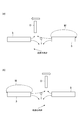
- FIG. 1 shows the use structure of a position detection apparatus provided with the position detection apparatus which concerns on one Embodiment. It is a figure which shows the magnetic force line of a 1st bias magnet and a 2nd bias magnet. It is a figure which shows the relationship between the position of a detection target object, and the direction of a magnetic field. It is a graph which shows the relationship between the movement amount of a detection target object, and the angle of the magnetic force line in the position of a detection element. It is a figure which shows the use structure of the position detection apparatus which concerns on other embodiment.
- FIG. 1 is a diagram illustrating a usage structure of a position detection device including a position detection device according to an embodiment.
- the position detection device usage structure 100 includes a position detection device 1 and a detection object D.
- the position detection device 1 detects the position of the moving detection object D.
- the position detection device 1 includes a first bias magnet (first magnet) 3, a second bias magnet (second magnet) 5, and a detection element 7.
- first magnet first magnet
- second bias magnet second magnet
- detection element 7 a detection element 7.
- three orthogonal directions (X direction, Y direction, and Z direction) shown in FIG. 1 are defined, and these three directions may be used for the description.
- the detection object D is a soft magnetic material (magnetic material).
- the soft magnetic material is, for example, iron or an iron alloy.
- the detection object D has, for example, a disk shape (plate shape) (a circular shape when viewed from the X direction). In FIG. 1, the form in which the detection target D is rectangular as viewed from the Z direction is shown as an example, but the actual shape of the detection target D is not limited to this.
- the detection object D moves along the X direction (opposite direction to be described later) as indicated by an arrow in FIG.
- the first bias magnet 3 and the second bias magnet 5 are, for example, neodymium magnets (rare earth magnets) or ferrite magnets.
- the first bias magnet 3 and the second bias magnet 5 have the same shape.
- each of the first bias magnet 3 and the second bias magnet 5 has a rectangular shape (bar shape).
- the first bias magnet 3 and the second bias magnet 5 are disposed so that the same polarity (magnetic pole) faces each other.
- the first bias magnet 3 and the second bias magnet 5 are arranged so that the N poles face each other in the X direction.
- the first bias magnet 3 and the second bias magnet 5 are configured such that the end face (N pole face) 3a of the first bias magnet 3 and the end face (N pole face) 5a of the second bias magnet 5 are in the Y direction. They are arranged to face each other so as to extend in parallel in the (Z direction).
- the first bias magnet 3 and the second bias magnet 5 are such that a straight line L connecting the center of the end face 3a of the first bias magnet 3 and the center of the end face 5a of the second bias magnet 5 is parallel to the X direction. It is arranged to become. That is, the facing direction of the first bias magnet 3 and the second bias magnet 5 is the X direction.
- the interval between the first bias magnet 3 and the second bias magnet 5 is appropriately set according to the amount of movement of the detection object D that moves along the X direction.
- the interval between the first bias magnet 3 and the second bias magnet 5 is set to be at least equal to or greater than the maximum movement amount of the detection object D.
- the detection object D is located in a range between the first bias magnet 3 and the second bias magnet 5 when viewed from a direction orthogonal to the facing direction. That is, the detection object D is viewed from the line along the end surface 3a of the first bias magnet 3 (extending along the Y direction) and the line along the end surface 5a of the second bias magnet 5 when viewed from the Z direction. Move within the area (area) to be partitioned. The detection object D is positioned such that the thickness direction is along the X direction.
- the detecting element 7 detects the direction of the magnetic field generated by the first bias magnet 3 and the second bias magnet 5. Specifically, the detection element 7 indicates the direction (vector) of the magnetic field applied to the detection element 7 by the first bias magnet 3 and the second bias magnet 5, that is, the direction of the lines of magnetic force at the position of the detection element 7. To detect.
- a Hall element for example, a Hall element, a Hall IC (IntegratedIntegrCircuit), a GMR (Giant Magneto Resistive effect) element, or the like can be used.
- the detection element 7 has, for example, a configuration having a plurality of Hall elements and a magnetic yoke, or a configuration having a plurality of spin valve magnetoresistive elements.
- the detection element 7 has a magnetic field in a range between the first bias magnet 3 and the second bias magnet 5 when viewed from the direction orthogonal to the facing direction in a state where the detection object D acts in the direction of the magnetic field. It is arranged between the offset position and the detection object D.
- the state in which the detection object D is acting in the direction of the magnetic field is, as shown in FIG. 2, a magnetic field line M generated by the detection object D in the magnetic field generated by the first bias magnet 3 and the second bias magnet 5. This is a state in which a change occurs from the direction of the magnetic field when the detection target D is not present due to the shielding and / or absorption of.
- the position where the magnetic field is canceled is a position where the magnetic field of the first bias magnet 3 and the magnetic field of the second bias magnet 5 opposite to the magnetic field cancel each other, and is a so-called zero magnetic field. is there.
- the zero magnetic field is a straight line in FIG. 2 when the detection object D is located at the center between the first bias magnet 3 and the second bias magnet 5 and above the straight line L, for example. It is a portion indicated by a black circle on L.
- a part of the detection element 7 is located between the first bias magnet 3 and the second bias magnet 5 and is disposed between the zero magnetic field and the detection object D. Specifically, as shown in FIG. 2, the detection element 7 is disposed above the straight line L and at the center of the distance between the first bias magnet 3 and the second bias magnet 5. Yes. The detection element 7 outputs a signal indicating the direction of the detected magnetic field.
- the detection object D when the detection object D is located at an intermediate point between the first bias magnet 3 and the second bias magnet 5 (immediately above the detection element 7), The magnetic fields of the first bias magnet 3 and the second bias magnet 5 are substantially equally affected.
- the direction of the magnetic field detected by the detection element 7 at the position of the detection element 7 is an upward direction (Y direction) as indicated by an arrow in FIG.
- the magnetic field generated by the first bias magnet 3 and the second bias magnet 5 changes at the position of the detection element 7.
- the lines of magnetic force M change with the movement.
- the lines of magnetic force generated from the first bias magnet 3 are absorbed and / or shielded by the detection object D. Therefore, the influence of the magnetic field of the second bias magnet 5 is large on the direction of the magnetic field detected by the detection element 7.
- the direction of the magnetic field detected by the detection element 7 is the leftward direction as shown by the arrow in FIG.
- the lines of magnetic force M change with the movement.
- the lines of magnetic force generated from the second bias magnet 5 are absorbed and / or shielded by the detection object D. Therefore, the influence of the magnetic field of the first bias magnet 3 is large on the direction of the magnetic field detected by the detection element 7.
- the direction of the magnetic field detected by the detection element 7 is the rightward direction as shown by the arrow in FIG.
- the direction of the magnetic field at the position of the detection element 7 changes as the detection object D moves.
- the position of the detection object D is detected based on the direction of the magnetic field at the position of the detection element 7.
- the position of the detection object D is associated with the direction of the magnetic field in a one-to-one relationship.
- the position detection device 1 detects (identifies) the position of the detection target D by detecting the direction of the magnetic field.
- the amount of movement of the detection target D can be detected by detecting the position of the detection target D.
- FIG. 4 is a graph showing the relationship between the amount of movement of the detection object D and the direction of the magnetic field at the position of the detection element 7.
- the horizontal axis indicates the amount of movement of the detection object D in the X direction
- the vertical axis indicates the direction of the magnetic field at the position of the detection element 7 (the angle formed by the direction of the lines of magnetic force relative to a predetermined reference) [deg. ] Is shown.
- the direction of the magnetic field on the vertical axis is when the detection object D is located at an intermediate point between the first bias magnet 3 and the second bias magnet 5 (directly above the detection element 7). “90 deg”.
- the position detection device 1 can detect a change in the direction of the magnetic field at least in the range of 0 to 180 [deg]. Thereby, the position detection apparatus 1 can detect the movement of the detection target D over a wide range (for example, 15 mm to 20 mm).
- the first bias magnet 3 and the second bias magnet 5 are arranged to face each other with the same polarity.
- the detection element 7 detects the direction at the position of the detection element 7 of the magnetic field that changes due to the movement of the detection object D in the facing direction of the two bias magnets 3 and 5.
- the magnetic field generated by the two bias magnets 3 and 5 with the same pole facing each other is established with a delicate balance of the lines of magnetic force generated from the bias magnets 3 and 5. For this reason, the direction of the magnetic field changes greatly when it receives an external action such as shielding and / or absorption of magnetic field lines.
- the position detection device 1 can detect a change in the direction of the magnetic field accompanying the movement of the detection target D at the position of the detection element 7 even when the detection target D has little effect on the magnetic field. Therefore, the position detection device 1 can detect the positions of various detection objects D in a wide range.
- the detection object D is located in a range between the first bias magnet 3 and the second bias magnet 5 when viewed from the direction orthogonal to the facing direction.
- the detection object D moves in a range between the first bias magnet 3 and the second bias magnet 5.
- the detection element 7 can detect the change in the direction of the magnetic field more reliably.
- the position of the detection object D can be detected with high accuracy.
- the detection element 7 is located between the first bias magnet 3 and the second bias magnet 5 when viewed from the direction orthogonal to the facing direction in a state where the detection object D acts in the direction of the magnetic field. And the detection object D are arranged between the position where the magnetic field is canceled in the range of. In this configuration, the direction of the magnetic field can be reliably detected by the detection element 7. Therefore, the position of the detection object D can be detected with high accuracy.
- the detection object D is a soft magnetic material.
- the detection target D itself is a soft magnetic material such as iron, it is not necessary to provide a magnet on the detection target D. Therefore, since it is not necessary to secure a region for attaching a magnet or the like in the detection target D, various positions of the detection target D can be detected.
- the detection target D has a disk shape.
- the detection object D is a disk (plate) shape, it is easy to shield and / or absorb the lines of magnetic force generated by the first bias magnet 3 and the second bias magnet 5. Therefore, the action (influence) on the magnetic field of the detection object D can be increased. As a result, the change in the direction of the magnetic field accompanying the movement of the detection object D becomes significant, so that the position of the detection object can be detected with higher accuracy.
- first bias magnet 3 and the second bias magnet 5 have been described as an example in which each of the first bias magnet 3 and the second bias magnet 5 has a rectangular shape (bar shape).
- shapes of the first bias magnet 3 and the second bias magnet 5 are as follows. It is not limited to this.
- the first bias magnet 3 and the second bias magnet 5 may be, for example, a disk shape or an annular shape.
- the first bias magnet 3 and the second bias magnet 5 have been described as an example in which the first bias magnet 3 and the second bias magnet 5 have the same shape.
- the first bias magnet 3 and the second bias magnet 5 have shapes (sizes). May be different. As long as the relationship in which the direction of the magnetic field detected by the detection element 7 is associated with the position of the detection target D is established, the shapes of the magnets may be different.
- the detection object D is positioned above the first bias magnet 3 and the second bias magnet 5, that is, the first bias magnet 3 and the second bias.
- the form which is not located between the magnets 5 was demonstrated to an example.
- the detection object D is positioned between the first bias magnet 3 and the second bias magnet 5, that is, a region between the first bias magnet 3 and the second bias magnet 5. May be at least partially located (invaded). Specifically, the tip of the detection object D is located in a region between the first bias magnet 3 and the second bias magnet 5.
- the positions of the first bias magnet 3 and the second bias magnet 5 can be easily set with respect to the detection object D, and the positions of the detection object D and the first bias magnet 3 and the second bias magnet 5 can be set. It is possible to suppress the occurrence of deviation. Thereby, the effect
- the detection object D itself is described as an example of a soft magnetic material, but the detection object D is not limited to this.
- the detection object D may have a magnetic body (soft magnetic body).
- the detection target D may have a form in which a magnetic body (magnet, metal, etc.) is provided on the detection target (those formed of a material other than the magnetic body).
- the number and shape of the magnetic body may be set as appropriate according to the configuration of the detection target.
- the position of the detection target can be detected even when the number of magnetic bodies is one.
- the N poles of the first bias magnet 3 and the second bias magnet 5 are arranged to face each other in the X direction.
- the first bias magnet 3 and the second bias magnet 5 are described.
- the S poles may be arranged to face each other.
- the first bias magnet 3 and the second bias magnet 5 may be arranged so that different polarities face each other.
- the 1st bias magnet 3 and the 2nd bias magnet 5 are arrange
- a configuration in which and are opposed to each other has been described.
- the form in which the first bias magnet 3 and the second bias magnet 5 face each other is not limited to this.
- the first bias magnet 3 and the second bias magnet 5 are configured such that a virtual line along the end surface 3a of the first bias magnet 3 and a virtual line along the end surface 5a of the second bias magnet 5 form a predetermined angle. And may be opposed.
- the extending direction of the first bias magnet 3 and the extending direction of the second bias magnet 5 do not have to be located on the same straight line.
- the opposing direction of the first bias magnet 3 and the second bias magnet 5 is an extending direction of a straight line connecting the center of the end surface 3a and the center of the end surface 5a.
- the detection element 7 is located above the straight line L, and a part of the detection element 7 is located between the first bias magnet 3 and the second bias magnet 5.
- the position of is not limited to this.
- the detection element 7 should just be arrange
- FIG. the detection element 7 should just be arrange
Landscapes
- Physics & Mathematics (AREA)
- General Physics & Mathematics (AREA)
- Transmission And Conversion Of Sensor Element Output (AREA)
- Measurement Of Length, Angles, Or The Like Using Electric Or Magnetic Means (AREA)
Abstract
位置検出装置1は、第1磁石3及び第2磁石5と、第1磁石3及び第2磁石5により発生する磁界の向きを検出する検出素子7と、を備え、第1磁石3と第2磁石5とは、同じ極性が対向して配置されており、第1磁石3と第2磁石5との対向方向における検出対象物Dの移動により、検出素子7によって検出される磁界の向きが変化する。
Description
本発明は、位置検出装置及び位置検出装置の使用構造に関する。
従来の位置検出装置として、例えば、特許文献1に記載された装置が知られている。特許文献1に記載の位置検出装置は、N極とS極とが交互に着磁された磁気部材と、磁気部材の磁極配列面に対向する磁気抵抗効果素子と、を備えている。磁気抵抗効果素子は、複数の磁石を含んで構成されており、検出対象物に設けられる。
上述のように、磁気抵抗効果素子は、複数の磁石を含んで構成されている。しかしながら、検出対象物の構成によっては、複数個の磁石を取り付ける領域を確保できない場合がある。そのため、従来の位置検出装置では、適用できる検出対象物に制限があった。また、磁石の数を少なくすると、磁界への作用が小さくなるため、磁界の向きの変化が小さくなる。そのため、検出対象物の移動量が大きい場合、検出対象物の位置によっては、磁界の向きの変化を捉えることが難しくなる。したがって、検出対象物の位置を検出できる範囲が小さかった。
本発明の一側面は、種々の検出対象物の位置を広範囲で検出できる位置検出装置及び位置検出装置の使用構造を提供することを目的とする。
本発明の一側面に係る位置検出装置は、磁性体である検出対象物の位置を検出する位置検出装置であって、第1磁石及び第2磁石と、第1磁石及び第2磁石により発生する磁界の向きを検出する検出素子と、を備え、第1磁石と第2磁石とは、同じ極性が対向して配置されており、第1磁石と第2磁石との対向方向における検出対象物の移動により、検出素子によって検出される磁界の向きが変化する。
本発明の一側面に係る位置検出装置では、第1磁石と第2磁石とは、同じ極性が対向して配置されている。検出素子は、この2つの磁石の対向方向における検出対象物の移動により変化する磁界の検出素子の位置における向きを検出する。同極が対向する2つの磁石により発生する磁界は、各磁石から発生する磁力線の微妙なバランスで成立している。そのため、磁界の向きは、磁力線の遮蔽及び/又は吸収といった外部からの作用を受けると大きく変化する。そのため、位置検出装置では、検出対象物による磁界への作用が小さい場合であっても、検出素子の位置において、検出対象物の移動に伴う磁界の向きの変化を検出できる。したがって、位置検出装置では、種々の検出対象物の位置を広範囲で検出できる。
一実施形態においては、検出対象物は、対向方向に直交する方向から見て、第1磁石と第2磁石との間の範囲に位置していてもよい。この構成では、検出対象物は、第1磁石と第2磁石との間の範囲で移動する。これにより、検出対象物の移動が、磁界の向きに効果的に作用する。したがって、検出素子は、磁界の向きの変化をより確実に検出できる。その結果、検出対象物の位置を精度良く検出できる。
一実施形態においては、検出対象物は、少なくとも一部が第1磁石と第2磁石との間に位置していてもよい。この構成では、検出対象物に対して第1磁石及び第2磁石の位置を容易に設定でき、検出対象物と第1磁石及び第2磁石との位置にずれが生じることを抑制できる。これにより、検出対象物の移動による磁界の向きへの作用をより正確なものとすることができる。したがって、検出素子は、磁界の向きの変化をより確実に検出できる。その結果、検出対象物の位置を精度良く検出できる。
一実施形態においては、検出素子は、検出対象物が磁界の向きに作用している状態において、対向方向に直交する方向から見て、第1磁石と第2磁石との間の範囲で磁界が相殺されている位置と、検出対象物との間に配置されていてもよい。この構成では、検出素子により、磁界の向きを確実に検出できる。したがって、検出対象物の位置を精度良く検出できる。
一実施形態においては、検出対象物は、軟磁性体であってもよい。検出対象物自体が鉄等の軟磁性体である場合、検出対象物に磁石等を設ける必要がない。したがって、検出対象物において磁石等を取り付ける領域を確保しなくてもよいため、種々の検出対象物の位置の検出が可能となる。
一実施形態においては、検出対象物は、板状であってもよい。検出対象物が板状である場合、磁石により発生した磁力線を遮蔽及び/又は吸収し易い。したがって、検出対象物の磁界への作用(影響)を大きくすることができる。その結果、検出対象物の移動に伴う磁界の向きの変化が顕著となるため、検出対象物の位置をより精度良く検出することができる。
本発明に係る位置検出装置の使用構造は、第1磁石及び第2磁石と、第1磁石及び第2磁石により発生する磁界の向きを検出する検出素子と、を有する位置検出装置と、磁性体からなり、移動によって磁界の向きに作用する検出対象物と、を備え、第1磁石と第2磁石とは、同じ極性が対向して配置されており、第1磁石と第2磁石との対向方向における検出対象物の移動により、検出素子によって検出される磁界の向きが変化する。
この位置検出装置の使用構造では、位置検出装置の第1磁石と第2磁石とは、第1磁石と第2磁石とは、同じ極性が対向して配置されている。検出素子は、この2つの磁石の対向方向における検出対象物の移動により変化する磁界の検出素子の位置における向きを検出する。同極が対向する2つの磁石により発生する磁界は、各磁石から発生する磁力線の微妙なバランスで成立している。そのため、磁界の向きは、磁力線の遮蔽及び/又は吸収といった外部からの作用を受けると大きく変化する。そのため、位置検出装置では、検出対象物による磁界への作用が小さい場合であっても、検出素子の位置において、検出対象物の移動に伴う磁界の向きの変化を検出できる。したがって、位置検出装置の使用構造では、種々の検出対象物の位置を広範囲で検出できる。
本発明の一側面によれば、種々の検出対象物の位置を広範囲で検出できる。
以下、添付図面を参照して、本発明の好適な実施形態について詳細に説明する。なお、図面の説明において同一又は相当要素には同一符号を付し、重複する説明は省略する。
図1は、一実施形態に係る位置検出装置を備える位置検出装置の使用構造を示す図である。図1に示されるように、位置検出装置の使用構造100は、位置検出装置1と、検出対象物Dと、を備えている。位置検出装置1は、移動する検出対象物Dの位置を検出する。位置検出装置1は、第1バイアス磁石(第1磁石)3と、第2バイアス磁石(第2磁石)5と、検出素子7と、を備えている。以下の説明では、図1に示す直交する3方向(X方向、Y方向、Z方向)を定義し、この3方向を説明に用いることもある。
最初に、位置検出装置1により位置が検出される検出対象物Dについて説明する。検出対象物Dは、軟磁性体(磁性体)である。軟磁性体は、例えば、鉄、又は、鉄合金等である。検出対象物Dは、例えば、円盤状(板状)を呈している(X方向から見て円形状を呈している)。図1では、Z方向から見て、検出対象物Dが矩形状である形態を一例に示しているが、実際の検出対象物Dの形状はこれに限定されない。検出対象物Dは、図1において矢印で示されるように、X方向(後述する対向方向)に沿って移動する。
続いて、位置検出装置1の各構成について説明する。第1バイアス磁石3及び第2バイアス磁石5は、例えば、ネオジウム磁石(希土類磁石)、又は、フェライト磁石等である。第1バイアス磁石3と第2バイアス磁石5は、同じ形状を呈している。本実施形態では、第1バイアス磁石3及び第2バイアス磁石5のそれぞれは、長方形状(棒状)を呈している。
第1バイアス磁石3と第2バイアス磁石5とは、同じ極性(磁極)が対向して配置されている。本実施形態では、第1バイアス磁石3と第2バイアス磁石5とは、N極同士がX方向において対向するように配置されている。具体的には、第1バイアス磁石3と第2バイアス磁石5とは、第1バイアス磁石3の端面(N極面)3aと第2バイアス磁石5の端面(N極面)5aとがY方向(Z方向)において平行に延在するように、対向して配置されている。
本実施形態では、第1バイアス磁石3と第2バイアス磁石5とは、第1バイアス磁石3の端面3aの中心と第2バイアス磁石5の端面5aの中心とを結ぶ直線LがX方向に平行となるように配置されている。すなわち、第1バイアス磁石3と第2バイアス磁石5との対向方向は、X方向である。第1バイアス磁石3と第2バイアス磁石5との間隔は、X方向に沿って移動する検出対象物Dの移動量に応じて適宜設定される。第1バイアス磁石3と第2バイアス磁石5との間隔は、少なくとも、検出対象物Dの最大移動量以上に設定されている。検出対象物Dは、上記対向方向に直交する方向から見て、第1バイアス磁石3と第2バイアス磁石5との間の範囲に位置する。すなわち、検出対象物Dは、Z方向から見て、第1バイアス磁石3の端面3aに沿った線(Y方向に沿って延在)と第2バイアス磁石5の端面5aに沿った線とにより区画される範囲(領域)内で移動する。検出対象物Dは、厚み方向がX方向に沿うように位置する。
検出素子7は、第1バイアス磁石3及び第2バイアス磁石5により発生する磁界の向きを検出する。具体的には、検出素子7は、第1バイアス磁石3及び第2バイアス磁石5により当該検出素子7に対して印加された磁界の向き(ベクトル)、すなわち検出素子7の位置における磁力線の向きを検出する。検出素子7としては、例えば、ホール素子、ホールIC(Integrated Circuit)、又は、GMR(Giant Magneto Resistive effect)素子等を用いることができる。具体的には、検出素子7は、例えば、複数のホール素子と磁性体ヨークとを有する構成、又は、複数のスピンバルブ型磁気抵抗素子を有する構成とされている。
検出素子7は、検出対象物Dが磁界の向きに作用している状態において、対向方向に直交する方向から見て、第1バイアス磁石3と第2バイアス磁石5との間の範囲で磁界が相殺されている位置と、検出対象物Dとの間に配置されている。検出対象物Dが磁界の向きに作用している状態とは、図2に示されるように、第1バイアス磁石3と第2バイアス磁石5とにより発生する磁界において、検出対象物Dによる磁力線Mの遮蔽及び/又は吸収により、検出対象物Dが存在していない場合の磁界の向きから変化が生じている状態である。磁界が相殺されている位置は、第1バイアス磁石3の磁界と、この磁界とは逆向きの第2バイアス磁石5の磁界とが互いに打ち消しあっている位置であり、いわゆるゼロ磁界となる点である。本実施形態では、ゼロ磁界は、第1バイアス磁石3と第2バイアス磁石5との間の中心で且つ直線Lよりも上方に検出対象物Dが位置している場合、例えば、図2において直線L上に黒丸で示す部分となる。
本実施形態では、検出素子7は、第1バイアス磁石3と第2バイアス磁石5との間に一部が位置し、ゼロ磁界と検出対象物Dとの間に配置されている。具体的には、検出素子7は、図2に示されるように、直線Lよりも図示上方で、且つ、第1バイアス磁石3と第2バイアス磁石5との間の距離の中心に配置されている。検出素子7は、検出した磁界の向きを示す信号を出力する。
続いて、上記構成を有する位置検出装置1による検出対象物Dの位置の検出方法について、図2及び図3を参照して説明する。図2及び図3においては、磁力線Mを模式的に示している。
図2に示されるように、検出対象物Dが第1バイアス磁石3と第2バイアス磁石5との中間地点(検出素子7の直上)に位置しているときには、検出素子7に対して、第1バイアス磁石3及び第2バイアス磁石5の磁界がそれぞれ略均等に影響する。このとき、検出素子7の位置において検出素子7により検出される磁界の向きは、図2において矢印で示されるように、上向きの方向(Y方向)となる。
位置検出装置1では、検出対象物Dが移動すると、検出素子7の位置において、第1バイアス磁石3と第2バイアス磁石5とにより発生する磁界に変化が生じる。具体的には、図3(a)に示されるように、検出対象物Dが図示左側に移動すると、その移動に伴い磁力線Mが変化する。このとき、第1バイアス磁石3から発生する磁力線は、検出対象物Dに吸収及び/又は遮蔽される。そのため、検出素子7において検出される磁界の向きには、第2バイアス磁石5の磁界の影響が大きくなる。これにより、検出素子7において検出される磁界の向きは、図3(a)において矢印で示されるように、左向きの方向となる。
図3(b)に示されるように、検出対象物Dが図示右側に移動すると、その移動に伴い磁力線Mが変化する。このとき、第2バイアス磁石5から発生する磁力線は、検出対象物Dに吸収及び/又は遮蔽される。そのため、検出素子7において検出される磁界の向きには、第1バイアス磁石3の磁界の影響が大きくなる。これにより、検出素子7において検出される磁界の向きは、図3(b)において矢印で示されるように、右向きの方向となる。
以上のように、検出素子7の位置における磁界は、検出対象物Dの移動に伴い向きが変化する。位置検出装置1では、検出素子7の位置における磁界の向きに基づいて、検出対象物Dの位置を検出する。位置検出装置1では、磁界の向きに検出対象物Dの位置が1対1の関係で対応付けられている。位置検出装置1は、磁界の向きを検出することにより、検出対象物Dの位置を検出(特定)する。位置検出装置1では、検出対象物Dの位置を検出することにより、検出対象物Dの移動量を検出することが可能である。
図4は、検出対象物Dの移動量と検出素子7の位置における磁界の向きとの関係を示すグラフである。図4において、横軸は、検出対象物DのX方向における移動量を示し、縦軸は、検出素子7の位置における磁界の向き(磁力線の向きが所定の基準に対して成す角度)[deg]を示している。縦軸の磁界の向きは、図2に示されるように、検出対象物Dが第1バイアス磁石3と第2バイアス磁石5との中間地点(検出素子7の直上)に位置しているときを「90deg」としている。
図4に示されるように、検出対象物Dが図3(a)に示されるように図示左側に移動した場合には、検出素子7の位置における磁界の向きは、「90deg」を基準として「+」(~180deg)となる。検出対象物Dが図3(b)に示されるように図示右側に移動した場合には、検出素子7の位置における磁界の向きは、「90deg」を基準として「-」(~0deg)となる。このように、位置検出装置1では、少なくとも、0~180[deg]の範囲において磁界の向きの変化を検出できる。これにより、位置検出装置1は、検出対象物Dの移動を広範囲(例えば、15mm~20mm)にわたって検出できる。
以上説明したように、本実施形態に係る位置検出装置1では、第1バイアス磁石3と第2バイアス磁石5とは、同じ極性が対向して配置されている。検出素子7は、この2つのバイアス磁石3,5の対向方向における検出対象物Dの移動により変化する磁界の検出素子7の位置における向きを検出する。同極が対向する2つのバイアス磁石3,5により発生する磁界は、各バイアス磁石3,5から発生する磁力線の微妙なバランスで成立している。そのため、磁界の向きは、磁力線の遮蔽及び/又は吸収といった外部からの作用を受けると大きく変化する。そのため、位置検出装置1では、検出対象物Dの磁界への作用が小さい場合であっても、検出素子7の位置において、検出対象物Dの移動に伴う磁界の向きの変化を検出できる。したがって、位置検出装置1では、種々の検出対象物Dの位置を広範囲で検出できる。
本実施形態では、検出対象物Dは、対向方向に直交する方向から見て、第1バイアス磁石3と第2バイアス磁石5との間の範囲に位置している。この構成では、検出対象物Dは、第1バイアス磁石3と第2バイアス磁石5との間の範囲で移動する。これにより、検出対象物Dの移動が、磁界の向きに効果的に作用する。したがって、検出素子7は、磁界の向きの変化をより確実に検出できる。その結果、検出対象物Dの位置を精度良く検出できる。
本実施形態では、検出素子7は、検出対象物Dが磁界の向きに作用している状態において、対向方向に直交する方向から見て、第1バイアス磁石3と第2バイアス磁石5との間の範囲で磁界が相殺されている位置と、検出対象物Dとの間に配置されている。この構成では、検出素子7により、磁界の向きを確実に検出できる。したがって、検出対象物Dの位置を精度良く検出できる。
本実施形態では、検出対象物Dは、軟磁性体である。検出対象物D自体が鉄等の軟磁性体である場合、検出対象物Dに磁石を設ける必要がない。したがって、検出対象物Dにおいて磁石等を取り付ける領域を確保しなくてもよいため、種々の検出対象物Dの位置の検出が可能となる。
本実施形態では、検出対象物Dは、円盤状を呈している。検出対象物Dが円盤(板)状である場合、第1バイアス磁石3及び第2バイアス磁石5により発生した磁力線を遮蔽及び/又は吸収し易い。したがって、検出対象物Dの磁界への作用(影響)を大きくすることができる。その結果、検出対象物Dの移動に伴う磁界の向きの変化が顕著となるため、検出対象物の位置をより精度良く検出することができる。
本発明は、上記実施形態に限定されない。例えば、上記実施形態では、第1バイアス磁石3及び第2バイアス磁石5のそれぞれが長方形状(棒状)を呈する形態を一例に説明したが、第1バイアス磁石3及び第2バイアス磁石5の形状はこれに限定されない。第1バイアス磁石3及び第2バイアス磁石5は、例えば、円盤状、円環状等であってもよい。
上記実施形態では、第1バイアス磁石3と第2バイアス磁石5とが同形状である形態を一例に説明したが、第1バイアス磁石3と第2バイアス磁石5とは、形状(大きさ)が異なっていてもよい。検出素子7により検出される磁界の向きと検出対象物Dの位置とが対応付けられた関係が成立していれば、磁石の形状は異なっていてもよい。
上記実施形態では、検出対象物Dが、図1に示されるように、第1バイアス磁石3及び第2バイアス磁石5よりも図示上方に位置している、すなわち第1バイアス磁石3と第2バイアス磁石5との間に位置していない形態を一例に説明した。しかし、検出対象物Dは、図5に示されるように、第1バイアス磁石3と第2バイアス磁石5との間に位置、すなわち第1バイアス磁石3と第2バイアス磁石5との間の領域に少なくとも一部が位置(侵入)していてもよい。具体的には、検出対象物Dの先端が、第1バイアス磁石3と第2バイアス磁石5との間の領域に位置している。この構成では、検出対象物Dに対して第1バイアス磁石3及び第2バイアス磁石5の位置を容易に設定でき、検出対象物Dと第1バイアス磁石3及び第2バイアス磁石5との位置にずれが生じることを抑制できる。これにより、検出対象物Dの移動による磁界の向きへの作用をより正確なものとすることができる。したがって、検出素子7は、磁界の向きの変化をより確実に検出できる。その結果、検出対象物Dの位置を精度良く検出できる。
上記実施形態では、検出対象物D自体が軟磁性体である形態を一例に説明したが、検出対象物Dの形態はこれに限定されない。検出対象物Dは、磁性体(軟磁性体)を有していてもよい。例えば、検出対象物Dは、検出対象物(磁性体以外の材料で形成されているもの)に磁性体(磁石、金属等)を設ける形態であってもよい。この場合、磁性体の個数及び形状等は、検出対象物の構成に合わせて適宜設定されればよい。本発明に係る位置検出装置では、磁性体が1個の場合であっても、検出対象物の位置を検出できる。
上記実施形態では、第1バイアス磁石3及び第2バイアス磁石5のN極同士がX方向において対向して配置されている形態を一例に説明したが、第1バイアス磁石3と第2バイアス磁石5とは、S極同士が対向して配置されてもよい。要は、第1バイアス磁石3と第2バイアス磁石5とは、異なる極性同士が対向して配置されていればよい。
上記実施形態では、第1バイアス磁石3の端面3aと第2バイアス磁石5の端面5aとがY方向において平行に延在するように配置することで、第1バイアス磁石3と第2バイアス磁石5とが対向する形態を一例に説明した。しかし、第1バイアス磁石3と第2バイアス磁石5とが対向する形態はこれに限定されない。例えば、第1バイアス磁石3と第2バイアス磁石5とは、第1バイアス磁石3の端面3aに沿った仮想線と第2バイアス磁石5の端面5aに沿った仮想線とが所定の角度を成して対向してもよい。すなわち、第1バイアス磁石3の延在方向と第2バイアス磁石5の延在方向とが同一直線上に位置していなくてもよい。この場合、第1バイアス磁石3と第2バイアス磁石5との対向方向は、端面3aの中心と端面5aの中心とを結ぶ直線の延在方向であり、上記実施形態と同様に、X方向となる。
上記実施形態では、検出素子7が直線Lの上方に位置し且つ一部が第1バイアス磁石3と第2バイアス磁石5との間に位置している形態を一例に説明したが、検出素子7の位置はこれに限定されない。検出素子7は、ゼロ磁界と検出対象物Dとの間に配置されていればよい。また、検出素子7は、上記対向方向に直交する方向から見て、第1バイアス磁石3と第2バイアス磁石5との間の範囲に配置されていればよい。すなわち、検出素子7は、Z方向から見て、第1バイアス磁石3の端面3aに沿った線(Y方向に沿って延在)と第2バイアス磁石5の端面5aに沿った線とにより区画される範囲(領域)内に配置されればよい。
1…位置検出装置、3…第1バイアス磁石(第1磁石)、5…第2バイアス磁石(第2磁石)、7…検出素子、100…位置検出装置の使用構造、D…検出対象物。
Claims (7)
- 磁性体である検出対象物の位置を検出する位置検出装置であって、
第1磁石及び第2磁石と、
前記第1磁石及び前記第2磁石により発生する磁界の向きを検出する検出素子と、を備え、
前記第1磁石と前記第2磁石とは、同じ極性が対向して配置されており、
前記第1磁石と前記第2磁石との対向方向における前記検出対象物の移動により、前記検出素子によって検出される前記磁界の向きが変化する、位置検出装置。 - 前記検出対象物は、前記対向方向に直交する方向から見て、前記第1磁石と前記第2磁石との間の範囲に位置する、請求項1に記載の位置検出装置。
- 前記検出対象物は、少なくとも一部が前記第1磁石と前記第2磁石との間に位置する、請求項2に記載の位置検出装置。
- 前記検出素子は、前記検出対象物が前記磁界の向きに作用している状態において、前記対向方向に直交する方向から見て、前記第1磁石と前記第2磁石との間の範囲で前記磁界が相殺されている位置と、前記検出対象物との間に配置されている、請求項2又は3に記載の位置検出装置。
- 前記検出対象物は、軟磁性体である、請求項1~4のいずれか一項に記載の位置検出装置。
- 前記検出対象物は、板状を呈している、請求項1~5のいずれか一項に記載の位置検出装置。
- 第1磁石及び第2磁石と、前記第1磁石及び前記第2磁石により発生する磁界の向きを検出する検出素子と、を有する位置検出装置と、
磁性体からなり、移動によって前記磁界の向きに作用する検出対象物と、を備え、
前記第1磁石と前記第2磁石とは、同じ極性が対向して配置されており、
前記第1磁石と前記第2磁石との対向方向における前記検出対象物の移動により、前記検出素子によって検出される前記磁界の向きが変化する、位置検出装置の使用構造。
Priority Applications (3)
| Application Number | Priority Date | Filing Date | Title |
|---|---|---|---|
| DE112016001825.8T DE112016001825T5 (de) | 2015-04-20 | 2016-04-13 | Positionsdetektionseinrichtung und struktur zum verwenden einer positionsdetektionseinrichtung |
| CN201680002822.0A CN106716070B (zh) | 2015-04-20 | 2016-04-13 | 位置检测装置以及位置检测装置的使用结构 |
| US15/511,456 US10215588B2 (en) | 2015-04-20 | 2016-04-13 | Position detecting device and structure for using position detecting device |
Applications Claiming Priority (2)
| Application Number | Priority Date | Filing Date | Title |
|---|---|---|---|
| JP2015086114A JP6464907B2 (ja) | 2015-04-20 | 2015-04-20 | 位置検出装置及び位置検出装置の使用構造 |
| JP2015-086114 | 2015-04-20 |
Publications (1)
| Publication Number | Publication Date |
|---|---|
| WO2016171059A1 true WO2016171059A1 (ja) | 2016-10-27 |
Family
ID=57143072
Family Applications (1)
| Application Number | Title | Priority Date | Filing Date |
|---|---|---|---|
| PCT/JP2016/061940 Ceased WO2016171059A1 (ja) | 2015-04-20 | 2016-04-13 | 位置検出装置及び位置検出装置の使用構造 |
Country Status (5)
| Country | Link |
|---|---|
| US (1) | US10215588B2 (ja) |
| JP (1) | JP6464907B2 (ja) |
| CN (1) | CN106716070B (ja) |
| DE (1) | DE112016001825T5 (ja) |
| WO (1) | WO2016171059A1 (ja) |
Families Citing this family (3)
| Publication number | Priority date | Publication date | Assignee | Title |
|---|---|---|---|---|
| JP6986002B2 (ja) * | 2018-11-26 | 2021-12-22 | Tdk株式会社 | 磁気センサ装置 |
| JP7156432B2 (ja) * | 2020-05-28 | 2022-10-19 | Tdk株式会社 | 位置検出装置、レンズモジュールおよび撮像装置 |
| JP7532461B2 (ja) | 2022-09-06 | 2024-08-13 | Tdk株式会社 | 位置検出装置、位置検出モジュール及びクラッチシステム |
Citations (4)
| Publication number | Priority date | Publication date | Assignee | Title |
|---|---|---|---|---|
| JPS5245953A (en) * | 1975-10-09 | 1977-04-12 | Nippon Steel Corp | Method for inspecting metal body by use of disturbances in blanced |
| JPH04282481A (ja) * | 1991-03-11 | 1992-10-07 | Matsushita Electric Ind Co Ltd | 磁電変換器 |
| WO1993018369A1 (en) * | 1992-03-02 | 1993-09-16 | Seiko Epson Corporation | Displacement sensor |
| JP2010038597A (ja) * | 2008-08-01 | 2010-02-18 | Actuator Design:Kk | 磁気利用の位置検出方法及び位置検出センサ |
Family Cites Families (14)
| Publication number | Priority date | Publication date | Assignee | Title |
|---|---|---|---|---|
| US4017867A (en) * | 1976-02-25 | 1977-04-12 | Bell Telephone Laboratories, Incorporated | Antenna assembly producing steerable beam and null |
| JPS58154615A (ja) * | 1982-03-10 | 1983-09-14 | Copal Co Ltd | 磁気検出装置 |
| KR900004780B1 (ko) * | 1985-09-13 | 1990-07-05 | 후지쓰 가부시끼가이샤 | 자기(磁氣) 센서를 사용한 위치 검출장치 |
| CA1264183A (en) * | 1986-12-15 | 1990-01-02 | Wagih Z. Fam | Poynting vector probe for measuring electric power |
| DE4319322C2 (de) * | 1993-06-11 | 1998-04-23 | Heidenhain Gmbh Dr Johannes | Positionsmeßeinrichtung |
| US5859531A (en) * | 1996-07-25 | 1999-01-12 | Maurice; Lisa Brackenbury | Displacement apparatus using a magnetic optic sensor and position dependent magnetic field |
| JP4097848B2 (ja) * | 1999-07-06 | 2008-06-11 | 東芝エレベータ株式会社 | エレベータ案内装置 |
| JP4582298B2 (ja) | 2004-07-08 | 2010-11-17 | Tdk株式会社 | 磁気式位置検出装置 |
| JP5362188B2 (ja) * | 2007-03-29 | 2013-12-11 | キヤノン電子株式会社 | 磁性体検出センサ |
| JP5013146B2 (ja) * | 2009-12-03 | 2012-08-29 | Tdk株式会社 | 磁気式位置検出装置 |
| CN103038659B (zh) * | 2010-07-30 | 2015-07-08 | 三菱电机株式会社 | 磁性体检测装置 |
| DE102012214916A1 (de) * | 2012-08-22 | 2014-03-20 | Robert Bosch Gmbh | Sensoranordnung zur Erfassung von Drehwinkeln an einem drehbewegten Bauteil |
| JP2014199182A (ja) * | 2013-03-29 | 2014-10-23 | Tdk株式会社 | 磁気センサシステム |
| US9574906B2 (en) * | 2013-10-28 | 2017-02-21 | Hitachi Metals, Ltd. | Magnetic medium for magnetic encoder, magnetic encoder and method for manufacturing magnetic medium |
-
2015
- 2015-04-20 JP JP2015086114A patent/JP6464907B2/ja active Active
-
2016
- 2016-04-13 CN CN201680002822.0A patent/CN106716070B/zh active Active
- 2016-04-13 WO PCT/JP2016/061940 patent/WO2016171059A1/ja not_active Ceased
- 2016-04-13 US US15/511,456 patent/US10215588B2/en active Active
- 2016-04-13 DE DE112016001825.8T patent/DE112016001825T5/de active Pending
Patent Citations (4)
| Publication number | Priority date | Publication date | Assignee | Title |
|---|---|---|---|---|
| JPS5245953A (en) * | 1975-10-09 | 1977-04-12 | Nippon Steel Corp | Method for inspecting metal body by use of disturbances in blanced |
| JPH04282481A (ja) * | 1991-03-11 | 1992-10-07 | Matsushita Electric Ind Co Ltd | 磁電変換器 |
| WO1993018369A1 (en) * | 1992-03-02 | 1993-09-16 | Seiko Epson Corporation | Displacement sensor |
| JP2010038597A (ja) * | 2008-08-01 | 2010-02-18 | Actuator Design:Kk | 磁気利用の位置検出方法及び位置検出センサ |
Also Published As
| Publication number | Publication date |
|---|---|
| US20170284827A1 (en) | 2017-10-05 |
| CN106716070A (zh) | 2017-05-24 |
| DE112016001825T5 (de) | 2017-12-28 |
| US10215588B2 (en) | 2019-02-26 |
| JP2016205935A (ja) | 2016-12-08 |
| JP6464907B2 (ja) | 2019-02-06 |
| CN106716070B (zh) | 2019-06-18 |
Similar Documents
| Publication | Publication Date | Title |
|---|---|---|
| US9644994B2 (en) | Magnetic sensor | |
| JP7208246B2 (ja) | 磁性ターゲットの回転動きの間の磁場影響力 | |
| US8102172B2 (en) | Position detector including magnetoresistive elements | |
| WO2017073151A1 (ja) | 位置検知装置 | |
| JP2009192261A (ja) | 直線変位検出装置 | |
| US20150145506A1 (en) | Magnetic sensor | |
| JP5408508B2 (ja) | 位置検出装置 | |
| CN113324564B (zh) | 位置检测装置和使用其的位置检测系统及转向系统 | |
| JP5079846B2 (ja) | 位置検出装置 | |
| US20160033587A1 (en) | Magnetic field measuring device | |
| JP5653262B2 (ja) | ストローク量検出装置 | |
| WO2015174409A1 (ja) | 磁気センサ装置 | |
| JP6464907B2 (ja) | 位置検出装置及び位置検出装置の使用構造 | |
| JP2012208112A (ja) | 位置センサ、磁石部材及び磁石部材の製造方法 | |
| JP2009288158A (ja) | 回転角度検出装置 | |
| JP5500389B2 (ja) | ストローク量検出装置 | |
| JP6406531B2 (ja) | 磁気式位置検出装置 | |
| JP5875947B2 (ja) | 磁気センサ装置 | |
| WO2010095495A1 (ja) | 磁気検出装置 | |
| JP5012130B2 (ja) | 角度センサ | |
| JP2011169715A (ja) | 位置検出機構 | |
| JPH07294540A (ja) | 磁気検出装置 | |
| WO2016117497A1 (ja) | 変位検出装置 | |
| KR101823571B1 (ko) | 외부 공통 성분의 방해 자기장을 효과적으로 제거하는 센싱 장치 | |
| WO2020179636A1 (ja) | 位置検出装置および磁気センサ装置 |
Legal Events
| Date | Code | Title | Description |
|---|---|---|---|
| 121 | Ep: the epo has been informed by wipo that ep was designated in this application |
Ref document number: 16783080 Country of ref document: EP Kind code of ref document: A1 |
|
| WWE | Wipo information: entry into national phase |
Ref document number: 15511456 Country of ref document: US |
|
| WWE | Wipo information: entry into national phase |
Ref document number: 112016001825 Country of ref document: DE |
|
| 122 | Ep: pct application non-entry in european phase |
Ref document number: 16783080 Country of ref document: EP Kind code of ref document: A1 |