WO2016171039A1 - バスバ組付け型電流センサ - Google Patents
バスバ組付け型電流センサ Download PDFInfo
- Publication number
- WO2016171039A1 WO2016171039A1 PCT/JP2016/061811 JP2016061811W WO2016171039A1 WO 2016171039 A1 WO2016171039 A1 WO 2016171039A1 JP 2016061811 W JP2016061811 W JP 2016061811W WO 2016171039 A1 WO2016171039 A1 WO 2016171039A1
- Authority
- WO
- WIPO (PCT)
- Prior art keywords
- bus bar
- sensor
- module
- current sensor
- type current
- Prior art date
- Legal status (The legal status is an assumption and is not a legal conclusion. Google has not performed a legal analysis and makes no representation as to the accuracy of the status listed.)
- Ceased
Links
Images

Classifications
-
- G—PHYSICS
- G01—MEASURING; TESTING
- G01R—MEASURING ELECTRIC VARIABLES; MEASURING MAGNETIC VARIABLES
- G01R19/00—Arrangements for measuring currents or voltages or for indicating presence or sign thereof
- G01R19/0092—Arrangements for measuring currents or voltages or for indicating presence or sign thereof measuring current only
-
- G—PHYSICS
- G01—MEASURING; TESTING
- G01R—MEASURING ELECTRIC VARIABLES; MEASURING MAGNETIC VARIABLES
- G01R15/00—Details of measuring arrangements of the types provided for in groups G01R17/00 - G01R29/00, G01R33/00 - G01R33/26 or G01R35/00
- G01R15/14—Adaptations providing voltage or current isolation, e.g. for high-voltage or high-current networks
- G01R15/20—Adaptations providing voltage or current isolation, e.g. for high-voltage or high-current networks using galvano-magnetic devices, e.g. Hall-effect devices, i.e. measuring a magnetic field via the interaction between a current and a magnetic field, e.g. magneto resistive or Hall effect devices
- G01R15/202—Adaptations providing voltage or current isolation, e.g. for high-voltage or high-current networks using galvano-magnetic devices, e.g. Hall-effect devices, i.e. measuring a magnetic field via the interaction between a current and a magnetic field, e.g. magneto resistive or Hall effect devices using Hall-effect devices
-
- G—PHYSICS
- G01—MEASURING; TESTING
- G01R—MEASURING ELECTRIC VARIABLES; MEASURING MAGNETIC VARIABLES
- G01R15/00—Details of measuring arrangements of the types provided for in groups G01R17/00 - G01R29/00, G01R33/00 - G01R33/26 or G01R35/00
- G01R15/14—Adaptations providing voltage or current isolation, e.g. for high-voltage or high-current networks
- G01R15/20—Adaptations providing voltage or current isolation, e.g. for high-voltage or high-current networks using galvano-magnetic devices, e.g. Hall-effect devices, i.e. measuring a magnetic field via the interaction between a current and a magnetic field, e.g. magneto resistive or Hall effect devices
- G01R15/207—Constructional details independent of the type of device used
-
- H—ELECTRICITY
- H02—GENERATION; CONVERSION OR DISTRIBUTION OF ELECTRIC POWER
- H02G—INSTALLATION OF ELECTRIC CABLES OR LINES, OR OF COMBINED OPTICAL AND ELECTRIC CABLES OR LINES
- H02G5/00—Installations of bus-bars
- H02G5/04—Partially-enclosed installations, e.g. in ducts and adapted for sliding or rolling current collection
Definitions
- the present invention relates to a bus bar assembled type current sensor.
- current sensors for measuring battery current and motor drive current are mounted on hybrid cars and electric cars.
- Such a current sensor uses a Hall element or the like to measure a current flowing through a bus bar as a conductive member that connects various electric devices and the like.
- An object of the present invention is to provide a bus bar assembly type current sensor that can be easily inspected.
- a feature of the present invention is a bus bar assembly type current sensor, which is housed in a resin mold and a sensor module having a sensor unit provided in the resin mold, the casing, and the sensor unit.
- a bus bar module having a bus bar arranged in the vicinity of the sensor, and at least one of the sensor module and the bus bar module is provided with a temporary fixing portion for temporarily fixing the sensor module and the bus bar module in a separable manner.
- a bus bar assembly type current sensor is provided in which the sensor module and the bus bar module are each provided with a main fixing portion that integrally fixes the sensor module and the bus bar module.
- the sensor module and the bus bar module can be handled separately until the sensor module and the bus bar module are temporarily fixed by the temporary fixing unit. For this reason, the characteristic of the sensor part of the sensor module can be easily inspected by inserting the bus bar of the checker into the sensor module.
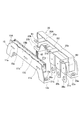
- bus bar assembly type current sensor 1 according to the embodiment will be described with reference to FIGS. 1 to 5.
- the same or equivalent members are denoted by the same reference numerals, and redundant description thereof is omitted.
- the current sensor 1 includes a sensor module 10 and a bus bar module 20.
- the sensor module 10 includes a sensor portion [ sensing elements] SN (SN1 to SN3).
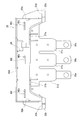
- the resin mold 10A has a beam portion [beam] 10B extending in the horizontal direction, and leg portions [legs] 12a and 12b respectively provided at both ends of the beam portion 10B.
- the leg portion 12a is provided with a sensor side communication screw hole 13a for fastening the sensor module 10 and the bus bar module 20 with screws in a state where the sensor module 10 is temporarily fixed by a temporary fixing portion described later. Yes.
- a sensor side communication screw hole 13b is formed in the leg 12b for fastening the sensor module 10 and the bus bar module 20 together with screws in a state where the sensor module 10 is temporarily fixed.
- the three sensor parts SN1 to SN3 are arranged at predetermined intervals in the horizontal direction of the beam part 10B.
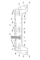
- Each of the sensor parts SN1 to SN3 includes a cylindrical magnetic body 150b having a cutout, and a Hall element 150a disposed in the cutout.
- the hall element 150 a is suspended from the substrate 100.
- the sensor units SN1 to SN3 are not limited to the above configuration. For example, sensor units SN1 to SN3 using magnetosensitive elements other than Hall elements may be employed. In the present embodiment, three sensor units SN1 to SN3 are provided, but only one sensor unit SN may be provided, or four or more sensor units SN may be provided.
- insertion holes 11a to 11b through which the bus bars B1 to B3 of the bus bar module 20 are inserted are formed. After the sensor module 10 and the bus bar module 20 are assembled, the bus bars B1 to B3 are arranged in the vicinity of the sensor units SN1 to SN3, and the currents flowing through the bus bars B1 to B3 can be measured by the sensor units SN1 to SN3.
- Engaged portions [engaging portions] (temporarily-fixing portions) 25a, 25b, 27a and 27b, which will be described later, of the bus bar module 20 are engaged with the outer edge of the beam portion 10B.
- portions] (temporary fixing portions) 15a, 15b, 17a and 17b are provided.
- the engaged parts (temporary fixing parts) 15a, 15b, 17a and 17b and the engaging parts (temporary fixing parts) 25a, 25b, 27a and 27b are engaged. Then, the sensor module 10 and the bus bar module 20 are temporarily fixed.
- the sensor module communication screw holes 13a and 13b of the sensor module 10 and bus bar side communication screw holes 23a and 23b (to be described later) of the bus bar module 20 are used. 10 and the bus bar module 20 can be easily fixed with screws.
- the outer surface of the leg 12b (12a) of the sensor module 10 is engaged with a protrusion 52b (52a) described later of the bus bar module 20.
- a groove 51b (51a) for aligning the sensor module 10 and the bus bar module 20 is formed. Therefore, when the sensor module 10 and the bus bar module 20 are assembled, the sensor module 10 and the bus bar module 20 can be easily aligned, and the assembling workability can be improved.
- 1 to 3 transmit the current values and the like of the bus bars B1 to B3 measured by the sensor units SN1 to SN3 to the external device via the substrate 100.
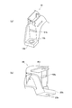
- the bus bar module 20 includes a casing 20A formed of resin or the like, and bus bars B (B1 to B3) accommodated in the casing 20A.
- Mounting holes 40a to 40c to which the bus bars B1 to B3 are respectively attached are formed in the casing 20A.
- the terminal portions 30a to 30c connected to the bus bars B1 to B3 are supported by the terminal support portions 21a to 21c and extend below the casing 20A.
- Legs 22a and 22b are provided at both ends of the casing 20A.
- the leg portion 22a is provided with a bus bar side communication screw hole 23a for fastening the sensor module 10 and the bus bar module 20 together with screws in a state where the bus bar module 20 is temporarily fixed by a temporary fixing portion described later.
- a bus bar-side communication screw hole 23b is formed in the leg portion 22b for fastening the sensor module 10 and the bus bar module 20 together with screws in a state where the bus bar module 20 is temporarily fixed.
- Engaging portions (temporary fixing portions) 25a, 25b, 27a, and 27b that can be engaged with the above-described engaged portions (temporary fixing portions) 15a, 15b, 17a, and 17b of the sensor module 10 are provided on the outer edge of the casing 20A. Is provided.
- the engaged portions (temporary fixing portions) 15a, 15b, 17a and 17b and the engaging portions (temporary fixing portions) 25a, 25b, 27a and 27b are respectively engaged.
- the sensor module 10 and the bus bar module 20 are temporarily fixed.
- the sensor module 10 When the sensor module 10 and the bus bar module 20 are temporarily fixed, the sensor module 10 is connected to the sensor module 10 using the sensor side communication screw holes 13a and 13b of the sensor module 10 and the bus bar side communication screw holes 23a and 23b of the bus bar module 20.
- the bus bar module 20 can be easily fixed with screws. That is, the engaged portions 15a, 15b, 17a and 17b, and the engaging portions 25a, 25b, 27a and 27b are provided as temporary fixing portions for temporarily fixing the sensor module 10 and the bus bar module 20.
- the sensor side communication screw holes 13a and 13b and the bus bar side communication screw holes 23a and 23b are permanently fixed (integratedly fixed) to the sensor module 10 and the bus bar module 20. ] Is provided.
- the inner surface of the leg portion 22b (22a) of the bus bar module 20 is engaged with the above-described groove portion 51b (51a) on the sensor module 10 side. 10 and the bus bar module 20 are formed with protrusions 52b (52a). Therefore, when the sensor module 10 and the bus bar module 20 are assembled, the sensor module 10 and the bus bar module 20 can be easily aligned, and the assembling workability can be improved.
- the groove 51b (51a) and the protrusion 52b (52a) are aligned, and the protrusion 52b (52a) is slid along the groove 51b (51a) (that is, the bus bar module 20 is moved to the sensor module). Manually push towards 10).
- the pushing of the bus bar module 20 into the sensor module 10 is completed, the engagement between the engaged portions 15a, 15b, 17a and 17b and the engaging portions 25a, 25b, 27a and 27b is also completed (temporarily fixed state).
- the sensor module 10 and the bus bar module 20 are temporarily fixed, the sensor module 10 and the bus bar module 20 are easily fixed with screws using the communication screw holes 13a, 13b, 23a and 23b.
- the temporarily fixed portions (the engaged portions 15a, 15b, 17a and 17b, and the engaging portions 25a, 25b, 27a and 27b) are provided in the vicinity of the sensor portions SN1 to SN3 (bus bars B1 to B3). Is preferred.
- the sensor module 10 is connected to the sensor module 10 by the temporary fixing portions (the engaged portions 15a, 15b, 17a and 17b and the engaging portions 25a, 25b, 27a and 27b). Until the bus bar module 20 is temporarily fixed, the sensor module 10 and the bus bar module 20 can be handled separately. Therefore, the characteristics of the sensor units SN1 to SN3 can be easily inspected by inserting checker inspection bus bars (not shown) into the insertion holes 11a to 11b of the sensor module 10 before being temporarily fixed to the bus bar module 20. it can.
- the sensor module 10 and the bus bar module 20 are provided with temporary fixing parts (engaged parts 15a, 15b, 17a, 17b and engaging parts 25a, 25b, 27a, 27b), the communication screw holes 13a, 13b. , 23a and 23b, the sensor module 10 and the bus bar module 20 can be easily fixed with screws.
- the sensor module 10 and the bus bar module 20 are fastened together and permanently fixed, so that handling properties and vibration resistance when mounted on various devices are improved. Durability can be improved.
- the bus bar assembly type current sensor 1 itself may be fixed to an external device by a screw for fastening the sensor module 10 and the bus bar module 20 together.
- the communication screw holes (main fixing portions) 13a, 13b, 23a and 23b are arranged in the vicinity of the terminal portions 30a and 30c of the bus bars B1 and B3 at both ends.
- the connection positions of the bus bars B1 and B3 to the external device and the communication screw holes 13a, 13b, 23a and 23b can be close to each other, and even if stress is applied to the bus bar B, the bus bar assembled type current sensor 1 is hardly broken. be able to.
- both the sensor module 10 and the bus bar module 20 are provided with temporary fixing portions.
- the sensor module 10 and the bus bar module 20 are temporarily fixed to at least one of the sensor module 10 and the bus bar module 20 in a separable manner.
- a temporary fixing part may be provided.
Landscapes
- Physics & Mathematics (AREA)
- General Physics & Mathematics (AREA)
- Measuring Instrument Details And Bridges, And Automatic Balancing Devices (AREA)
Priority Applications (1)
| Application Number | Priority Date | Filing Date | Title |
|---|---|---|---|
| US15/568,119 US10317435B2 (en) | 2015-04-23 | 2016-04-12 | Bus bar assemble type electric current sensor |
Applications Claiming Priority (2)
| Application Number | Priority Date | Filing Date | Title |
|---|---|---|---|
| JP2015088173A JP6533411B2 (ja) | 2015-04-23 | 2015-04-23 | バスバ組付け型電流センサ |
| JP2015-088173 | 2015-04-23 |
Publications (1)
| Publication Number | Publication Date |
|---|---|
| WO2016171039A1 true WO2016171039A1 (ja) | 2016-10-27 |
Family
ID=57143832
Family Applications (1)
| Application Number | Title | Priority Date | Filing Date |
|---|---|---|---|
| PCT/JP2016/061811 Ceased WO2016171039A1 (ja) | 2015-04-23 | 2016-04-12 | バスバ組付け型電流センサ |
Country Status (3)
| Country | Link |
|---|---|
| US (1) | US10317435B2 (enExample) |
| JP (1) | JP6533411B2 (enExample) |
| WO (1) | WO2016171039A1 (enExample) |
Cited By (1)
| Publication number | Priority date | Publication date | Assignee | Title |
|---|---|---|---|---|
| WO2022264728A1 (ja) * | 2021-06-14 | 2022-12-22 | 株式会社明電舎 | 電流センサ保持構造、電気機器及びインバータ装置 |
Families Citing this family (2)
| Publication number | Priority date | Publication date | Assignee | Title |
|---|---|---|---|---|
| JP7127633B2 (ja) * | 2019-11-05 | 2022-08-30 | 株式会社デンソー | センサユニット |
| WO2021241082A1 (ja) | 2020-05-29 | 2021-12-02 | アルプスアルパイン株式会社 | 電流センサ |
Citations (4)
| Publication number | Priority date | Publication date | Assignee | Title |
|---|---|---|---|---|
| JPH0383418U (enExample) * | 1989-12-14 | 1991-08-26 | ||
| JPH06276646A (ja) * | 1993-03-15 | 1994-09-30 | Sumitomo Wiring Syst Ltd | リレーボックス |
| JP2006166528A (ja) * | 2004-12-03 | 2006-06-22 | Yazaki Corp | 電気接続箱 |
| JP2008082736A (ja) * | 2006-09-26 | 2008-04-10 | Yazaki Corp | 電流センサの仮固定構造 |
Family Cites Families (9)
| Publication number | Priority date | Publication date | Assignee | Title |
|---|---|---|---|---|
| JPH09270325A (ja) * | 1996-03-29 | 1997-10-14 | Tokin Corp | 電子部品 |
| DE102008012665A1 (de) * | 2008-03-05 | 2009-09-10 | Conti Temic Microelectronic Gmbh | Strommessvorrichtung mittels magnetempfindlichem Sensor für ein leistungselektronisches System |
| JP2010073767A (ja) * | 2008-09-17 | 2010-04-02 | Jtekt Corp | 多層回路基板 |
| JP5524540B2 (ja) * | 2009-09-01 | 2014-06-18 | 株式会社東海理化電機製作所 | 電流センサ |
| JP5687531B2 (ja) * | 2011-03-09 | 2015-03-18 | トヨタ自動車株式会社 | ノイズ低減装置およびバスバーモジュール |
| JP2013113631A (ja) * | 2011-11-25 | 2013-06-10 | Yazaki Corp | 電流検出装置 |
| JP2013238580A (ja) | 2011-12-28 | 2013-11-28 | Tdk Corp | 電流センサ |
| JP5982860B2 (ja) * | 2012-02-22 | 2016-08-31 | 住友電気工業株式会社 | 自動車用電流センサ組込み中継バスバー装置 |
| JP2015094603A (ja) * | 2013-11-08 | 2015-05-18 | ヤマハ株式会社 | 電流センサーの製造方法および電流センサー |
-
2015
- 2015-04-23 JP JP2015088173A patent/JP6533411B2/ja not_active Expired - Fee Related
-
2016
- 2016-04-12 US US15/568,119 patent/US10317435B2/en active Active
- 2016-04-12 WO PCT/JP2016/061811 patent/WO2016171039A1/ja not_active Ceased
Patent Citations (4)
| Publication number | Priority date | Publication date | Assignee | Title |
|---|---|---|---|---|
| JPH0383418U (enExample) * | 1989-12-14 | 1991-08-26 | ||
| JPH06276646A (ja) * | 1993-03-15 | 1994-09-30 | Sumitomo Wiring Syst Ltd | リレーボックス |
| JP2006166528A (ja) * | 2004-12-03 | 2006-06-22 | Yazaki Corp | 電気接続箱 |
| JP2008082736A (ja) * | 2006-09-26 | 2008-04-10 | Yazaki Corp | 電流センサの仮固定構造 |
Cited By (1)
| Publication number | Priority date | Publication date | Assignee | Title |
|---|---|---|---|---|
| WO2022264728A1 (ja) * | 2021-06-14 | 2022-12-22 | 株式会社明電舎 | 電流センサ保持構造、電気機器及びインバータ装置 |
Also Published As
| Publication number | Publication date |
|---|---|
| US20180113156A1 (en) | 2018-04-26 |
| JP2016206015A (ja) | 2016-12-08 |
| US10317435B2 (en) | 2019-06-11 |
| JP6533411B2 (ja) | 2019-06-19 |
Similar Documents
| Publication | Publication Date | Title |
|---|---|---|
| CN103124910B (zh) | 电流检测装置及其装接结构 | |
| KR101738781B1 (ko) | 자기 검출 장치 및 이를 포함하는 토크 센서 | |
| CN107402094B (zh) | 传感器单元、集磁模块以及传感器装置 | |
| US9086440B2 (en) | Current sensor | |
| CN102177415B (zh) | 用于检测旋转零件转角的装置 | |
| JP5673085B2 (ja) | 電流検出装置 | |
| US20090039880A1 (en) | Electric current detector having detector element holder coupled to magnetic core casing | |
| CN105044439B (zh) | 一种隧道磁电阻电流传感器 | |
| CN108534873B (zh) | 用于秤的负荷传感器 | |
| JP2010078586A (ja) | 電流検出装置の組付け構造 | |
| WO2016171039A1 (ja) | バスバ組付け型電流センサ | |
| CA2694779A1 (en) | Sensing device for sensing position of rotor | |
| US20180331525A1 (en) | Electrical connection box | |
| JP6262579B2 (ja) | 電流センサーと導電部材との組み付け構造 | |
| KR20090129766A (ko) | 차량의 스티어링 휠의 조향각 검출용 센서장치 및 그제조방법 | |
| JP2010185848A (ja) | 電流検出装置の組付け構造及び組付け方法 | |
| JP5755852B2 (ja) | 温度センサ及び温度センサの製造方法 | |
| JP5704352B2 (ja) | 電流センサ | |
| JP5683511B2 (ja) | 電流センサ | |
| US8941018B2 (en) | Connecting element and method for manufacturing a connecting element | |
| JP2021032796A (ja) | 電流センサ | |
| JP2016206015A5 (enExample) | ||
| JP2015068824A (ja) | 導体及びこれを備えた電流センサ | |
| KR102825036B1 (ko) | 코어리스 전류센서 | |
| JP2009507236A (ja) | 電気的な構成部材と電気的な供給ラインとを有するハウジング |
Legal Events
| Date | Code | Title | Description |
|---|---|---|---|
| 121 | Ep: the epo has been informed by wipo that ep was designated in this application |
Ref document number: 16783060 Country of ref document: EP Kind code of ref document: A1 |
|
| DPE1 | Request for preliminary examination filed after expiration of 19th month from priority date (pct application filed from 20040101) | ||
| WWE | Wipo information: entry into national phase |
Ref document number: 15568119 Country of ref document: US |
|
| NENP | Non-entry into the national phase |
Ref country code: DE |
|
| 122 | Ep: pct application non-entry in european phase |
Ref document number: 16783060 Country of ref document: EP Kind code of ref document: A1 |