WO2016170743A1 - 圧力センサ - Google Patents
圧力センサ Download PDFInfo
- Publication number
- WO2016170743A1 WO2016170743A1 PCT/JP2016/001891 JP2016001891W WO2016170743A1 WO 2016170743 A1 WO2016170743 A1 WO 2016170743A1 JP 2016001891 W JP2016001891 W JP 2016001891W WO 2016170743 A1 WO2016170743 A1 WO 2016170743A1
- Authority
- WO
- WIPO (PCT)
- Prior art keywords
- signal
- pressure
- unit
- value
- determination
- Prior art date
- Legal status (The legal status is an assumption and is not a legal conclusion. Google has not performed a legal analysis and makes no representation as to the accuracy of the status listed.)
- Ceased
Links
Images


Classifications
-
- G—PHYSICS
- G01—MEASURING; TESTING
- G01L—MEASURING FORCE, STRESS, TORQUE, WORK, MECHANICAL POWER, MECHANICAL EFFICIENCY, OR FLUID PRESSURE
- G01L9/00—Measuring steady of quasi-steady pressure of fluid or fluent solid material by electric or magnetic pressure-sensitive elements; Transmitting or indicating the displacement of mechanical pressure-sensitive elements, used to measure the steady or quasi-steady pressure of a fluid or fluent solid material, by electric or magnetic means
-
- G—PHYSICS
- G01—MEASURING; TESTING
- G01L—MEASURING FORCE, STRESS, TORQUE, WORK, MECHANICAL POWER, MECHANICAL EFFICIENCY, OR FLUID PRESSURE
- G01L19/00—Details of, or accessories for, apparatus for measuring steady or quasi-steady pressure of a fluent medium insofar as such details or accessories are not special to particular types of pressure gauges
- G01L19/08—Means for indicating or recording, e.g. for remote indication
- G01L19/12—Alarms or signals
Definitions
- the present disclosure relates to a pressure sensor for measuring pressure.
- Patent Document 1 proposes a pressure measuring device having a diaphragm in which a part of a sensor wafer is locally thinly formed. This pressure measuring device acquires the sensor output corresponding to the pressure value by electrically measuring the deformation amount of the diaphragm deformed by the pressure of the pressure medium.
- This disclosure is intended to provide a pressure sensor that can achieve both high accuracy of sensor output on the low pressure side in the pressure detection range and expansion of the pressure detection range.
- the pressure sensor detects a pressure in the pressure detection range, outputs a detection signal corresponding to the pressure, and inputs the detection signal from the sensing unit, and the detection signal is input to a predetermined amplification factor.
- an amplifying unit that amplifies and outputs as a pressure signal.
- the pressure sensor receives a pressure signal from the amplifying unit and determines whether or not the signal value of the pressure signal is lower than the reference value with respect to the reference value that divides the pressure detection range into two.
- the determination part which determines according to is provided.
- the pressure sensor determines that the signal value of the pressure signal is not lower than the reference value when the determination unit determines that the signal value of the pressure signal is not lower than the reference value.
- a signal output unit for outputting a signal is provided.
- the pressure detection range is not limited by the structure of the sensing unit. That is, the pressure detection range can be set wider than the conventional one. Therefore, it is possible to achieve both high accuracy of the signal value on the low pressure side in the pressure detection range and expansion of the pressure detection range.
- the pressure sensor according to the present embodiment detects the pressure of the pressure medium.
- the pressure sensor includes a sensor chip 1 and a circuit chip 2.
- the sensor chip 1 and the circuit chip 2 are electrically connected by a VS wire 3, a VP wire 4, and a VM wire 5.
- Each of the wires 3 to 5 is a bonding wire.
- a circuit constituting a pressure sensor is formed in the sensor chip 1 and the circuit chip 2.
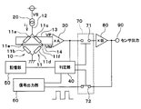
- the pressure sensor includes a sensing unit 10, a power supply unit 20, a first amplification unit 30, a determination unit 40, a storage unit 50, a signal output unit 60, a signal switching unit 70, and A second amplifying unit 80 is provided.
- the sensing unit 10 is formed on the sensor chip 1.
- the power supply unit 20, the first amplification unit 30, the determination unit 40, the storage unit 50, the signal output unit 60, the signal switching unit 70, and the second amplification unit 80 are formed in the circuit chip 2.
- the sensor chip 1 and the circuit chip 2 are formed based on a semiconductor substrate such as a silicon substrate. That is, each component of the pressure sensor is formed on the sensor chip 1 and the circuit chip 2 by a semiconductor process.
- the sensor chip 1 and the circuit chip 2 are accommodated in a case (not shown).
- the sensing unit 10 detects the pressure in the pressure detection range.
- the sensing unit 10 is formed, for example, in a diaphragm (not shown) in which a part of the sensor chip 1 is thinned.
- the pressure detection range is a preset range, for example, a range of 0 Pa to several MPa. The pressure detection range is adjusted by the thickness and size of the diaphragm. If the voltage range of the power supply is 0 V to 5 V, the pressure detection range is 0.5 V to 4.5 V, for example.
- the sensing unit 10 includes a bridge circuit unit 11, a VS wiring 12, a VP wiring 13, and a VM wiring 14.
- the bridge circuit unit 11 includes a first resistor 11a, a second resistor 11b, a third resistor 11c, and a fourth resistor 11d whose resistance values change according to the application of pressure.
- the first resistor 11a and the second resistor 11b are connected in series, and the third resistor 11c and the fourth resistor 11d are connected in series.
- Each of the resistors 11a to 11d is a diffused resistor such as a P ++ type region or an N ⁇ type region formed in the diaphragm of the sensor chip 1.
- the VS wiring 12 is a wiring for applying an input voltage to the bridge circuit unit 11.
- a part of the VS wiring 12 is configured as the VS wire 3 described above.
- One of the VP wirings 13 is connected to the first middle point 11e of the first resistor 11a and the second resistor 11b, and the other is connected to the first amplifying unit 30.
- a part of the VP wiring 13 is configured as the VP wire 4 described above.
- One of the VM wirings 14 is connected to the second middle point 11f of the third resistor 11c and the fourth resistor 11d, and the other is connected to the first amplifying unit 30.
- a part of the negative electrode wiring is configured as the VM wire 5 described above.
- the sensing unit 10 outputs a potential difference between the first voltage at the first middle point 11e and the second voltage at the second middle point 11f as a detection signal based on the input voltage applied to the bridge circuit unit 11. Since the signal value of the detection signal changes in accordance with the magnitude of the pressure applied to the diaphragm of the sensor chip 1, the first voltage corresponding to the magnitude of the pressure is applied to the VP wiring 13 and the second voltage is set to VM. Applied to the wiring 14.
- the pressure detected by the diaphragm may be an absolute pressure or a differential pressure.
- the absolute pressure is detected by applying a vacuum pressure to one surface of the diaphragm and applying the pressure of the pressure medium to the other surface.
- the differential pressure is detected by the pressure applied to both sides of the diaphragm.
- the power supply unit 20 is configured as a constant current source that generates a constant current.
- the power supply unit 20 supplies the constant current (i) to the bridge circuit unit 11 via the VS wiring 12. As a result, an input voltage is applied to the bridge circuit unit 11.
- the power supply unit 20 may be a constant current source or a constant voltage source.
- the first amplifying unit 30 receives the detection signal from the sensing unit 10, amplifies the detection signal with a predetermined amplification factor, and outputs it as a pressure signal.
- the first amplifying unit 30 is configured to receive the first voltage and the second voltage from the bridge circuit unit 11 and amplify the difference voltage between the first voltage and the second voltage with a predetermined amplification factor. This is a differential amplifier circuit unit.
- the first amplifying unit 30 multiplies the signal value of the pressure signal by A.
- the determination unit 40 receives the pressure signal from the first amplifying unit 30, and determines whether the signal value of the pressure signal is lower than the reference value with respect to the reference value that divides the pressure detection range into two. Judge according to the criteria.
- the criterion is a threshold value set in advance for the signal value of the pressure signal.
- “dividing the pressure detection range into two parts” is not limited to dividing the pressure detection range into two equal parts.
- the reference value for dividing the pressure detection range into two is the median value that bisects the pressure detection range.
- the determination unit 40 determines whether the signal value of the pressure signal is a low-pressure side value or a high-pressure side value with reference to the reference value.
- the determination unit 40 has a function of determining whether or not the VS wiring 12, the VP wiring 13, and the VM wiring 14 are disconnected. That is, the determination unit 40 determines whether the signal value of the pressure signal is a value indicating the disconnection of the VS wiring 12 according to the determination criterion. Similarly, the determination unit 40 determines whether the signal value of the pressure signal is a value indicating the disconnection of the VP wiring 13 or the VM wiring 14 according to the determination criterion.
- the storage unit 50 is a storage unit in which determination criteria used for determination by the determination unit 40 are stored.
- the determination criterion includes four threshold values of first to fourth threshold values set for the signal value of the pressure signal. These threshold values are the smallest value of the first threshold value, and are the larger values in the order of the second threshold value, the third threshold value, and the fourth threshold value.
- the first threshold value is used to determine whether or not the VP wiring 13 is disconnected.
- the first threshold value and the second threshold value are used to determine whether the signal value of the pressure signal is a value on the low pressure side.
- the second threshold is a threshold corresponding to the signal value of the pressure signal that bisects the pressure detection range.
- the second threshold value and the third threshold value are used for determining whether the signal value of the pressure signal is a value on the high pressure side.
- the third threshold value and the fourth threshold value are used for determining disconnection of the VS wiring 12.
- the fourth threshold value is used to determine disconnection of the VM wiring 14.
- the storage unit 50 is a memory capable of writing and erasing data. That is, the criterion is stored in the storage unit 50 so as to be rewritable. Thereby, after manufacturing the product, it becomes possible to write the determination standard according to the situation and environment in which the pressure sensor is used, the measurement object, etc., and the versatility of the pressure sensor is improved.
- the determination unit 40 performs determination using these determination criteria stored in the storage unit 50.
- the determination unit 40 outputs the determination result to the signal output unit 60 and the signal switching unit 70.
- the signal output unit 60 generates and outputs a determination signal according to the determination result of the determination unit 40 when the determination unit 40 determines that the signal value of the pressure signal is not a value lower than the reference value.
- the determination signal is a signal indicating that the signal value of the pressure signal is not a value lower than the reference value.
- the determination signal is a signal indicating that the signal value of the pressure signal indicates the high voltage side, or a signal indicating disconnection of the wirings 12 to 14.
- the signal output unit 60 outputs a high-pressure signal indicating that the signal value of the pressure signal is a value on the high-pressure side with respect to the reference value as the determination signal.
- the signal output unit 60 outputs a VS disconnection signal indicating a disconnection of the VS wiring 12 as a determination signal.
- the signal output unit 60 outputs a VP disconnection signal indicating disconnection of the VP wiring 13 as a determination signal, and outputs a VM disconnection signal indicating disconnection of the VM wiring 14 as a determination signal.
- the high-voltage signal, the VS disconnection signal, the VP disconnection signal, and the VM disconnection signal that are determination signals are signals having different duty ratios, for example. These determination signals may be signals having a waveform such as a triangular wave, a sine wave, or a rectangular wave according to the determination result.
- the signal output unit 60 is a circuit that generates a plurality of determination signals according to the determination result.
- the signal switching unit 70 switches the output path according to the determination result to the determination unit 40 so that one of the output of the first amplification unit 30 and the output of the signal output unit 60 is output to the external device.
- the signal switching unit 70 includes a first switch 71 and a second switch 72.
- the first switch 71 connects the first amplification unit 30 and the second amplification unit 80.
- the second switch 72 connects the signal output unit 60 and the output terminal 90.
- Each of the switches 71 and 72 is configured as a semiconductor switch, for example.
- the signal switching unit 70 when the determination unit 40 determines that the signal value of the pressure signal is lower than the reference value, the signal switching unit 70 turns on the first switch 71 and turns off the second switch 72. By doing so, the pressure signal can be output to the outside.
- the signal switching unit 70 determines by turning off the first switch 71 and turning on the second switch 72. The signal can be output to the outside. As a result, either the pressure signal or the determination signal can be output from the pressure sensor to the outside.
- the second amplifying unit 80 receives the pressure signal from the first amplifying unit 30, amplifies the pressure signal with a predetermined amplification factor, and outputs it as a sensor output.
- the second amplifying unit 80 is configured as a differential amplifier circuit unit, for example.
- the second amplifying unit 80 multiplies the signal value of the pressure signal by B. Therefore, the pressure sensor amplifies the pressure signal by two stages and outputs it as the sensor output.
- the operation of the pressure sensor will be described. First, a description will be given of a normal state in which the wires 12 to 14 are not disconnected.
- a detection signal corresponding to the magnitude of the pressure is output from the sensing unit 10.
- the detection signal is multiplied by A by the first amplifying unit 30 and output as a pressure signal.
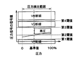
- the signal value of the pressure signal is in the range between the first threshold value and the third threshold value. Further, the signal value of the pressure signal changes almost linearly with respect to the pressure value. And it is determined by the determination part 40 whether the signal value of a pressure signal is a value of the low voltage
- the pressure detection range is shown in a range of 0% to 100%.
- the signal value of the pressure signal is included in the range from the first threshold value to the second threshold value
- the signal value of the pressure signal is a value on the lower pressure side than the reference value.
- the determination unit 40 turns on the first switch 71 and turns off the second switch 72.
- the pressure signal on the low pressure side is further multiplied by B by the second amplifying unit 80 and output as a sensor output. That is, as shown in FIG. 4, when the signal value of the pressure signal is a value on the low pressure side, a pressure signal that changes almost linearly according to the pressure value is output as the sensor output.
- the determination unit 40 turns off the first switch 71 and turns on the second switch 72. As a result, no pressure signal is output. Further, a high voltage signal is output as a determination signal from the signal output unit 60 according to the determination result of the determination unit 40. That is, as shown in FIG. 4, when the signal value of the pressure signal is a value on the high pressure side, a signal with a predetermined duty ratio is output as a sensor output.
- each of the wirings 12 to 14 has the highest possibility of disconnection of each of the wires 3 to 5, but there is also the possibility of disconnection of a portion formed in the sensor chip 1 or the circuit chip 2 of each of the wirings 12 to 14. .
- the determination unit 40 determines whether or not the signal value of the pressure signal is included in the range from the third threshold value to the fourth threshold value.
- the signal value of the pressure signal is included in the range from the third threshold value to the fourth threshold value, the VS wiring 12 is disconnected.
- the determination unit 40 determines whether or not the signal value of the pressure signal is smaller than the first threshold value. When the signal value of the pressure signal is smaller than the first threshold value, the VP wiring 13 is disconnected.
- the determination unit 40 determines whether or not the signal value of the pressure signal is larger than the fourth threshold value. When the signal value of the pressure signal is larger than the fourth threshold value, the VM wiring 14 is disconnected.
- the determination unit 40 turns off the first switch 71 and turns on the second switch 72.
- a determination signal is output from the signal output unit 60.
- a VS disconnection signal is output from the signal output unit 60 when the VP wiring 13 is disconnected, a VP disconnection signal is output from the signal output unit 60 when the VP wiring 13 is disconnected, and a signal output unit 60 when the VM wiring 14 is disconnected.
- a VM disconnection signal is output.
- the sensor output output from the pressure sensor as described above is input to an external device that uses the pressure value for control. Then, the content of the sensor output is identified in the external device and used for control or the like.
- the pressure signal on the low pressure side than the reference value in the pressure detection range detectable by the sensing unit 10 is amplified by the first amplification unit 30, the low pressure side in the pressure detection range.
- the pressure can be detected with high accuracy.
- the pressure signal is also amplified by the second amplifying unit 80, so that the accuracy of the signal value of the pressure signal can be improved.
- the signal value of the pressure signal is not a value lower than the reference value in the pressure detection range, a determination signal is generated.
- accuracy is not required for the pressure value on the high pressure side of the pressure detection range.
- the high pressure side pressure is applied to the sensing unit 10.
- a high pressure signal is output from the pressure sensor. For this reason, high-precision sensor output is not required for the entire pressure detection range, and high-precision sensor output is required on the low-pressure side, while it is only necessary to detect whether or not pressure is applied on the high-pressure side of the pressure detection range. It can meet the needs of pressure measurement.
- the pressure detection range is 0 to 1 MPa.
- the range in which pressure is actually detected with high accuracy is about 0 to 0.3 MPa.
- the pressure sensor according to the present embodiment can function not only as pressure measurement but also as a pressure switch.
- the first amplifying unit 30 corresponds to an “amplifying unit”.
- the VS wire 3 corresponds to an “input bonding wire”
- the VP wire 4 corresponds to a “first bonding wire”
- the VM wire 5 corresponds to a “second bonding wire”.
- VS wiring 12 corresponds to “input wiring”
- VP wiring 13 corresponds to “first wiring”
- VM wiring 14 corresponds to “second wiring”.
- the VS disconnection signal corresponds to the “input disconnection signal”
- the VP disconnection signal corresponds to the “first disconnection signal”
- the VM disconnection signal corresponds to the “second disconnection signal”.
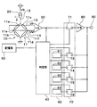
- the signal output unit 60 is configured to generate and output each determination signal. That is, the signal output unit 60 includes a first signal output unit 61 that generates and outputs a high-voltage signal, a second signal output unit 62 that generates and outputs a VS disconnection signal, and a third signal output unit that generates and outputs a VP disconnection signal. 63, a fourth signal output unit 64 for generating and outputting a VM disconnection signal. Each signal output unit 61 to 64 always outputs a signal.
- the signal switching unit 70 includes a third switch 73 corresponding to the first signal output unit 61, a fourth switch 74 corresponding to the second signal output unit 62, a fifth switch 75 corresponding to the third signal output unit 63, A sixth switch 76 corresponding to the fourth signal output unit 64 is provided.
- the signal output unit 60 does not need to generate a determination signal according to the determination result of the determination unit 40, turns on any of the switches 71 and 73 to 76 according to the determination result, and others. Can be turned off.
- the signal output unit 60 may be divided into a plurality of parts instead of one configuration.
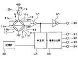
- the pressure sensor does not include the signal switching unit 70.
- the signal output unit 60 is connected to output terminals 91 to 94 corresponding to each determination signal.
- the signal output part 60 outputs a high voltage signal to the output terminal 91 according to the determination result of the determination part 40, outputs a VS disconnection signal to the output terminal 92, outputs a VP disconnection signal to the output terminal 93, VM A disconnection signal is output to the output terminal 94.
- the pressure signal is always output as the sensor output from the second amplifying unit 80, while the determination signal is output according to the determination result of the determination unit 40.
- the signal switching unit 70 can be dispensed with.
- the external device identifies the signal input from the pressure sensor and uses it for control.
- each of the resistors 11a to 11d constituting the sensing unit 10 is not a diffused resistor, but may have another configuration in which the resistance value changes according to the pressure.
- the second amplifying unit 80 is provided, but this is a configuration in which the pressure signal is further amplified to achieve high accuracy. Therefore, if the first amplifier 30 can sufficiently amplify the signal, the second amplifier 80 may not be provided in the pressure sensor.
- the pressure sensor may be configured without a disconnection detection function. In this case, the pressure sensor outputs a low pressure side pressure signal or a high pressure signal.
- the pressure sensor is not limited to the two-chip configuration of the sensor chip 1 and the circuit chip 2, and may be formed on one chip or may be formed on three chips. Since the wires 3 to 5 are unnecessary in the case of one chip, the determination unit 40 detects disconnection of the wirings 12 to 14 formed in one chip. On the other hand, in the case of three or more chips, since there is a high possibility of disconnection of the bonding wires connecting the chips, the disconnection of the bonding wires is detected.
- the determination criterion is stored in the storage unit 50, but the determination criterion may be set in the determination unit 40. Further, the determination criteria stored in the storage unit 50 may not be rewritable. That is, the determination reference data may be fixed in the storage unit 50.
Landscapes
- Physics & Mathematics (AREA)
- General Physics & Mathematics (AREA)
- Measuring Fluid Pressure (AREA)
Abstract
圧力センサは、圧力に応じた検出信号を出力するセンシング部(10)と、検出信号を所定の増幅率で増幅して圧力信号として出力する増幅部(30)と、判定部(40)と、信号出力部(60)と、を備える。判定部(40)は、圧力検出範囲を二分割する基準値に対して圧力信号の信号値が当該基準値よりも低圧側の値であるか否かを判定基準に従って判定する。判定部(40)によって圧力信号の信号値が基準値よりも低圧側の値ではないと判定された場合、信号出力部(60)は、圧力信号の信号値が基準値よりも低圧側の値でないことを示す判定信号を出力する。
Description
本出願は、2015年4月22日に出願された日本特許出願2015-87484号に基づくもので、ここにその記載内容を援用する。
本開示は、圧力を測定するための圧力センサに関する。
センサウェハの一部が局所的に薄く形成されたダイヤフラムを有する圧力測定デバイスが、特許文献1で提案されている。この圧力測定デバイスは、圧力媒体の圧力によって変形するダイヤフラムの変形量を電気的に測定することにより、圧力値に対応したセンサ出力を取得する。
圧力媒体の圧力が小さい場合にはダイヤフラムの変形量も小さい。この場合のダイヤフラムの変形は非線形の度合いが小さいので、ダイヤフラムの変形量に対応したセンサ出力はほぼ線型的に変化する。しかしながら、圧力媒体の圧力が大きくなるほどダイヤフラムの変形は非線形の度合いが大きくなるので、ダイヤフラムの変形量に応じたセンサ出力に含まれる非線形成分が大きくなってしまう。
そこで、必要とする圧力検出範囲ではセンサ出力に含まれる非線形成分が一定範囲に収まるようにダイヤフラムのサイズや厚みを調整することでダイヤフラムにおける非線形の変形を抑えることが考えられる。しかし、圧力検出範囲における低圧側ではダイヤフラムの変形そのものが非常に小さいために増幅回路によるセンサ出力の増幅が必要になる。また、圧力検出範囲の上限値に合わせた増幅率で低圧側のセンサ出力を増幅することになるので、低圧側の圧力を高精度に検出することができない。さらに、ダイヤフラムの変形量の範囲を大きくすることができないので、検出可能な圧力検出範囲が限られてしまう。
本開示は、圧力検出範囲における低圧側のセンサ出力の高精度化と圧力検出範囲の拡大との両立を図ることができる圧力センサを提供することを目的とする。
本開示の一態様において、圧力センサは、圧力検出範囲における圧力を検出すると共に、圧力に応じた検出信号を出力するセンシング部と、センシング部から検出信号を入力し、検出信号を所定の増幅率で増幅して圧力信号として出力する増幅部と、を備えている。
また、圧力センサは、増幅部から圧力信号を入力し、圧力検出範囲を二分割する基準値に対して圧力信号の信号値が当該基準値よりも低圧側の値であるか否かを判定基準に従って判定する判定部を備えている。
さらに、圧力センサは、判定部によって圧力信号の信号値が基準値よりも低圧側の値ではないと判定された場合、圧力信号の信号値が基準値よりも低圧側の値でないことを示す判定信号を出力する信号出力部を備えている。
これによると、圧力検出範囲において基準値よりも低圧側の圧力信号は増幅部によって増幅されるので、圧力検出範囲における低圧側の圧力を高精度に検出することができる。また、圧力を検出するためのセンシング部の構造を制限する必要がないので、圧力検出範囲がセンシング部の構造によって制限されない。すなわち、圧力検出範囲を従来よりも広く設定することができる。したがって、圧力検出範囲における低圧側の信号値の高精度化と圧力検出範囲の拡大との両立を図ることができる。
実施形態について図に基づいて説明する。なお、以下の各実施形態相互において、互いに同一もしくは均等である部分には、図中、同一符号を付してある。
(第1実施形態)
第1実施形態について図を参照して説明する。本実施形態に係る圧力センサは、圧力媒体の圧力を検出する。図1に示されるように、圧力センサは、センサチップ1及び回路チップ2を備えている。
第1実施形態について図を参照して説明する。本実施形態に係る圧力センサは、圧力媒体の圧力を検出する。図1に示されるように、圧力センサは、センサチップ1及び回路チップ2を備えている。
センサチップ1と回路チップ2とは、VSワイヤ3、VPワイヤ4、及びVMワイヤ5によって電気的に接続されている。各ワイヤ3~5は、ボンディングワイヤである。センサチップ1及び回路チップ2に圧力センサを構成する回路が形成されている。
具体的には、図2に示されるように、圧力センサは、センシング部10、電源部20、第1増幅部30、判定部40、記憶部50、信号出力部60、信号切替部70、及び第2増幅部80を備えている。センシング部10はセンサチップ1に形成されている。一方、電源部20、第1増幅部30、判定部40、記憶部50、信号出力部60、信号切替部70、及び第2増幅部80は回路チップ2に形成されている。
センサチップ1及び回路チップ2はシリコン基板等の半導体基板を元に形成されている。すなわち、圧力センサの各構成は半導体プロセスによってセンサチップ1及び回路チップ2に形成されている。センサチップ1及び回路チップ2は、図示しないケースに収容される。
センシング部10は、圧力検出範囲における圧力を検出する。センシング部10は、例えばセンサチップ1の一部が薄肉化された図示しないダイヤフラムに形成されている。圧力検出範囲は予め設定された範囲であり、例えば0Pa~数MPaの範囲である。圧力検出範囲は、ダイヤフラムの厚みやサイズ等によって調整されている。なお、電源の電圧範囲を0V~5Vとすると、圧力検出範囲は例えば0.5V~4.5Vである。
また、センシング部10は、ブリッジ回路部11、VS配線12、VP配線13、及びVM配線14を有している。ブリッジ回路部11は、圧力の印加に応じて抵抗値が変化する第1抵抗11a、第2抵抗11b、第3抵抗11c、及び第4抵抗11dによって構成されている。第1抵抗11aと第2抵抗11bとが直列接続され、第3抵抗11cと第4抵抗11dとが直列接続されている。各抵抗11a~11dは、センサチップ1のダイヤフラムに形成されたP++型領域やN--型領域等の拡散抵抗である。
VS配線12は、ブリッジ回路部11に入力電圧を印加するための配線である。VS配線12の一部が上記のVSワイヤ3として構成されている。
VP配線13は、一方が第1抵抗11aと第2抵抗11bとの第1中点11eに接続され、他方が第1増幅部30に接続されている。VP配線13の一部が上記のVPワイヤ4として構成されている。
VM配線14は、一方が第3抵抗11cと第4抵抗11dとの第2中点11fに接続され、他方が第1増幅部30に接続されている。負極配線の一部が上記のVMワイヤ5として構成されている。
センシング部10は、ブリッジ回路部11に印加される入力電圧に基づいて第1中点11eの第1電圧と第2中点11fの第2電圧との電位差を検出信号として出力する。センサチップ1のダイヤフラムに印加される圧力の大きさに応じて検出信号の信号値が変化するので、圧力の大きさに対応した第1電圧がVP配線13に印加されると共に第2電圧がVM配線14に印加される。
ダイヤフラムで検出される圧力は絶対圧でも差圧でも良い。絶対圧は、ダイヤフラムの一方の面に真空圧が印加され、他方の面に圧力媒体の圧力が印加されることで検出される。差圧はダイヤフラムの両面に印加される圧力によって検出される。
電源部20は、一定の電流を生成する定電流源として構成されている。電源部20は、定電流(i)をVS配線12を介してブリッジ回路部11に供給する。これにより、ブリッジ回路部11に入力電圧が印加される。なお、電源部20は、定電流源でも定電圧源でも良い。
第1増幅部30は、センシング部10から検出信号を入力し、検出信号を所定の増幅率で増幅して圧力信号として出力する。具体的には、第1増幅部30は、ブリッジ回路部11から第1電圧及び第2電圧を入力し、第1電圧と第2電圧との差電圧を所定の増幅率で増幅するように構成された差動増幅回路部である。本実施形態では、第1増幅部30は圧力信号の信号値をA倍する。
判定部40は、第1増幅部30から圧力信号を入力し、圧力検出範囲を二分割する基準値に対して圧力信号の信号値が当該基準値よりも低圧側の値であるか否かを判定基準に従って判定する。ここで、判定基準とは、圧力信号の信号値に対して予め設定された閾値である。
また、「圧力検出範囲を二分割する」とは、圧力検出範囲を二等分する場合に限られない。例えば圧力検出範囲を1/3と2/3とに二分割する場合も含まれる。本実施形態では、圧力検出範囲を二分割する基準値は、圧力検出範囲を二等分する中央値とする。これにより、判定部40は、圧力信号の信号値が基準値を基準として低圧側の値であるか、または高圧側の値であるかを判定する。
判定部40は、VS配線12、VP配線13、及びVM配線14の断線の有無を判定する機能を有している。すなわち、判定部40は、判定基準に従って、圧力信号の信号値がVS配線12の断線を示す値であるか否かを判定する。同様に、判定部40は、判定基準に従って、圧力信号の信号値がVP配線13またはVM配線14の断線を示す値であるか否かを判定する。
記憶部50は、判定部40の判定に用いられる判定基準が記憶された記憶手段である。本実施形態では、判定基準は、圧力信号の信号値に対して設定された第1~第4閾値の4つの閾値を含んでいる。これらの閾値は第1閾値が最も小さい値であり、第2閾値、第3閾値、第4閾値の順に大きな値になっている。
第1閾値は、VP配線13の断線の有無を判定するために用いられる。第1閾値及び第2閾値は、圧力信号の信号値が低圧側の値であるかを判定するために用いられる。第2閾値は、圧力検出範囲を二等分する圧力信号の信号値に対応した閾値である。
第2閾値及び第3閾値は、圧力信号の信号値が高圧側の値であるかを判定するために用いられる。第3閾値及び第4閾値は、VS配線12の断線を判定するために用いられる。第4閾値は、VM配線14の断線を判定するために用いられる。
記憶部50は、データの書き込み及び消去が可能なメモリである。すなわち、判定基準は、記憶部50において書き換え可能に記憶されている。これにより、製品の製造後、圧力センサが使用される状況や環境、測定対象等に応じた判定基準の書き込みが可能になり、圧力センサの汎用性が向上する。
判定部40は、記憶部50に記憶されたこれらの判定基準を用いて判定を行う。判定部40は、判定結果を信号出力部60及び信号切替部70に出力する。
信号出力部60は、判定部40によって圧力信号の信号値が基準値よりも低圧側の値ではないと判定された場合、判定部40の判定結果に応じた判定信号を発生及び出力する。判定信号は、圧力信号の信号値が基準値よりも低圧側の値でないことを示す信号である。本実施形態では、判定信号は、圧力信号の信号値が高圧側を示す信号や、各配線12~14の断線を示す信号である。
具体的には、信号出力部60は、判定信号として圧力信号の信号値が基準値よりも高圧側の値であることを示す高圧信号を出力する。また、信号出力部60は、判定信号としてVS配線12の断線を示すVS断線信号を出力する。さらに、信号出力部60は、判定信号としてVP配線13の断線を示すVP断線信号を出力し、判定信号としてVM配線14の断線を示すVM断線信号を出力する。
判定信号である高圧信号、VS断線信号、VP断線信号、及びVM断線信号は、例えばDuty比が異なる信号である。なお、これらの判定信号は、判定結果に応じた三角波、Sin波、矩形波等の波形の信号でも良い。このように、信号出力部60は、判定結果に応じた複数の判定信号を発生する回路である。
信号切替部70は、判定部40に判定結果に従って、第1増幅部30の出力と信号出力部60の出力とのいずれか一方が外部装置に出力されるように出力経路を切り替える。このため、信号切替部70は、第1スイッチ71及び第2スイッチ72を有している。第1スイッチ71は、第1増幅部30と第2増幅部80とを接続している。第2スイッチ72は、信号出力部60と出力端子90とを接続している。各スイッチ71、72は例えば半導体スイッチとして構成されている。
具体的には、判定部40によって圧力信号の信号値が基準値よりも低圧側の値であると判定された場合、信号切替部70は第1スイッチ71をONして第2スイッチ72をOFFすることにより圧力信号を外部に出力可能にする。一方、判定部40によって圧力信号の信号値が基準値よりも低圧側の値でないと判定された場合、信号切替部70は第1スイッチ71をOFFして第2スイッチ72をONすることにより判定信号を外部に出力可能にする。これにより、圧力信号及び判定信号のいずれか一方を圧力センサから外部に出力することができる。
第2増幅部80は、第1増幅部30から圧力信号を入力し、圧力信号を所定の増幅率で増幅してセンサ出力として出力する。第2増幅部80は例えば差動増幅回路部として構成されている。また、第2増幅部80は圧力信号の信号値をB倍する。したがって、圧力センサは圧力信号を2段増幅してセンサ出力として外部に出力する。
圧力センサの作動について説明する。まず、各配線12~14に断線がない正常時について説明する。センサチップ1のダイヤフラムに圧力媒体の圧力が印加されることでセンシング部10から圧力の大きさに応じた検出信号が出力される。検出信号は第1増幅部30でA倍されて圧力信号として出力される。
図3に示されるように、圧力信号の信号値は第1閾値と第3閾値との範囲にある。また、圧力信号の信号値は、圧力値に対してほぼ線形的に変化する。そして、判定部40によって圧力信号の信号値が基準値よりも低圧側の値であるか否かが判定される。すなわち、圧力信号の信号値が第1閾値から第2閾値までの範囲に含まれるか否かが判定される。なお、図3では圧力検出範囲を0%~100%の範囲で示している。
圧力信号の信号値が第1閾値から第2閾値までの範囲に含まれる場合は圧力信号の信号値が基準値よりも低圧側の値である。この場合、判定部40によって第1スイッチ71がONされ、第2スイッチ72がOFFされる。これにより、低圧側の圧力信号は第2増幅部80でさらにB倍されてセンサ出力として出力される。つまり、図4に示されるように、圧力信号の信号値が低圧側の値の場合、圧力値に応じてほぼ線形的に変化する圧力信号がセンサ出力として出力される。
一方、圧力信号の信号値が第2閾値よりも大きい場合、すなわち圧力信号の信号値が第2閾値から第3閾値までの範囲に含まれる場合は圧力信号の信号値が基準値よりも高圧側の値である。この場合、判定部40によって第1スイッチ71がOFFされ、第2スイッチ72がONされる。これにより、圧力信号は出力されない。また、判定部40の判定結果に応じて信号出力部60から判定信号として高圧信号が出力される。つまり、図4に示されるように、圧力信号の信号値が高圧側の値の場合、所定のDuty比の信号がセンサ出力として出力される。
続いて、各配線12~14が断線した場合について説明する。各配線12~14の断線は、各ワイヤ3~5の断線の可能性が最も高いが、各配線12~14のうちセンサチップ1や回路チップ2に形成された部分の断線の可能性もある。
図3に示されるように、VS配線12の断線時は、判定部40によって圧力信号の信号値が第3閾値から第4閾値までの範囲に含まれるか否かが判定される。圧力信号の信号値が第3閾値から第4閾値までの範囲に含まれる場合はVS配線12が断線している。
また、VP配線13の断線時は、判定部40によって圧力信号の信号値が第1閾値よりも小さい値であるか否かが判定される。圧力信号の信号値が第1閾値よりも小さい値の場合はVP配線13が断線している。
また、VM配線14の断線時は、判定部40によって圧力信号の信号値が第4閾値よりも大きい値であるか否かが判定される。圧力信号の信号値が第4閾値よりも大きい値の場合はVM配線14が断線している。
このような断線時では、判定部40によって第1スイッチ71がOFFされ、第2スイッチ72がONされる。また、信号出力部60から判定信号が出力される。VP配線13の断線時は信号出力部60からVS断線信号が出力され、VP配線13の断線時は信号出力部60からVP断線信号が出力され、VM配線14の断線時は信号出力部60からVM断線信号が出力される。これらの判定信号はそれぞれ異なるDuty比に設定されている。そして、これらの判定信号がセンサ出力として外部に出力される。
上記のように圧力センサから出力されたセンサ出力は、圧力値を制御に用いる外部装置に入力される。そして、外部装置においてセンサ出力の内容が識別され、制御等に用いられる。
以上説明したように、本実施形態では、センシング部10で検出可能な圧力検出範囲において基準値よりも低圧側の圧力信号は第1増幅部30によって増幅されるので、圧力検出範囲における低圧側の圧力を高精度に検出することができる。本実施形態では、圧力信号は第2増幅部80によっても増幅されるので、圧力信号の信号値の精度を向上させることができる。
また、圧力検出範囲において圧力信号の信号値が基準値よりも低圧側の値ではない場合、判定信号が生成される。言い換えると、圧力検出範囲の高圧側の圧力値については精度が不要である。このため、高圧側の圧力値を高精度に検出できるようにセンシング部10の構造を制限する必要がない。つまり、圧力検出範囲のおける低圧側の圧力値の精度を、高圧側の圧力値の精度に合わせる必要が無いので、圧力検出範囲を従来よりも広く設定することができる。したがって、圧力検出範囲における低圧側の信号値の高精度化と圧力検出範囲の拡大との両立を図ることができる。
さらに、本実施形態では、各配線12~14に断線が無い場合であって圧力信号の信号値が基準値よりも高圧側の場合はセンシング部10に高圧側の圧力が印加されていることを示す高圧信号が圧力センサから出力される。このため、圧力検出範囲の全体で高精度なセンサ出力が必要ではなく低圧側では高精度なセンサ出力が要求される一方、圧力検出範囲の高圧側では圧力印加の有無のみを検出できれば良い、という圧力測定のニーズに対応することができる。
具体的には、車両において圧力センサを使用するシステムでは、例えばAT油圧が測定される。この場合、圧力検出範囲は0~1MPaの範囲である。そして、実際に精度良く圧力検出したい範囲は0~0.3MPa程度である。このようなシステムにおいて、0.3MPaより高圧側では高い圧力が印加されていることが高圧信号によって判別可能になる。したがって、本実施形態に係る圧力センサは圧力測定だけでなく、圧力スイッチとしても機能させることができる。
第1増幅部30が「増幅部」に対応する。VSワイヤ3が「入力ボンディングワイヤ」に対応し、VPワイヤ4が「第1ボンディングワイヤ」に対応し、VMワイヤ5が「第2ボンディングワイヤ」に対応する。
VS配線12が「入力配線」に対応し、VP配線13が「第1配線」に対応し、VM配線14が「第2配線」に対応する。さらに、VS断線信号が「入力断線信号」に対応し、VP断線信号が「第1断線信号」に対応し、VM断線信号が「第2断線信号」に対応する。
(第2実施形態)
本実施形態では、第1実施形態と異なる部分について説明する。図5に示されるように、信号出力部60は、各判定信号をそれぞれ生成及び出力する構成になっている。すなわち、信号出力部60は、高圧信号を生成及び出力する第1信号出力部61、VS断線信号を生成及び出力する第2信号出力部62、VP断線信号を生成及び出力する第3信号出力部63、VM断線信号を生成及び出力する第4信号出力部64を有している。各信号出力部61~64は、常時、信号を出力している。
本実施形態では、第1実施形態と異なる部分について説明する。図5に示されるように、信号出力部60は、各判定信号をそれぞれ生成及び出力する構成になっている。すなわち、信号出力部60は、高圧信号を生成及び出力する第1信号出力部61、VS断線信号を生成及び出力する第2信号出力部62、VP断線信号を生成及び出力する第3信号出力部63、VM断線信号を生成及び出力する第4信号出力部64を有している。各信号出力部61~64は、常時、信号を出力している。
また、信号切替部70は、第1信号出力部61に対応した第3スイッチ73、第2信号出力部62に対応した第4スイッチ74、第3信号出力部63に対応した第5スイッチ75、第4信号出力部64に対応した第6スイッチ76を有している。
このような構成によると、信号出力部60は判定部40の判定結果に応じた判定信号を生成する必要がなく、判定結果に応じた各スイッチ71、73~76のいずれかをONし、その他をOFFすれば良い。以上のように、信号出力部60は一つの構成ではなく、複数に分割されていても良い。
(第3実施形態)
本実施形態では、第1、第2実施形態と異なる部分について説明する。図6に示されるように、圧力センサは、信号切替部70を備えていない。具体的には、信号出力部60は各判定信号に対応した出力端子91~94に接続されている。そして、信号出力部60は、判定部40の判定結果に応じて高圧信号を出力端子91に出力し、VS断線信号を出力端子92に出力し、VP断線信号を出力端子93に出力し、VM断線信号を出力端子94に出力する。
本実施形態では、第1、第2実施形態と異なる部分について説明する。図6に示されるように、圧力センサは、信号切替部70を備えていない。具体的には、信号出力部60は各判定信号に対応した出力端子91~94に接続されている。そして、信号出力部60は、判定部40の判定結果に応じて高圧信号を出力端子91に出力し、VS断線信号を出力端子92に出力し、VP断線信号を出力端子93に出力し、VM断線信号を出力端子94に出力する。
このような構成では、第2増幅部80から常に圧力信号がセンサ出力として出力される一方、判定部40の判定結果に応じて判定信号が出力される。出力端子90~94の数は多くなるが、信号切替部70を不要とすることができる。なお、外部装置は圧力センサから入力される信号を識別して制御に用いることになる。
(他の実施形態)
上記各実施形態で示された圧力センサの構成は一例であり、上記で示した構成に限定されることなく、他の構成とすることもできる。例えば、センシング部10を構成する各抵抗11a~11dは拡散抵抗ではなく、圧力に応じて抵抗値が変化する他の構成でも良い。
上記各実施形態で示された圧力センサの構成は一例であり、上記で示した構成に限定されることなく、他の構成とすることもできる。例えば、センシング部10を構成する各抵抗11a~11dは拡散抵抗ではなく、圧力に応じて抵抗値が変化する他の構成でも良い。
上記各実施形態では、第2増幅部80が設けられていたが、これは圧力信号をさらに増幅して高精度化を図った構成である。したがって、第1増幅部30で十分な信号増幅が可能である場合は圧力センサに第2増幅部80が設けられていなくても良い。
上記各実施形態では、各配線12~14の断線を検出する構成になっていたが、これは圧力センサの構成の一例である。したがって、圧力センサは断線検出機能を有しない構成でも良い。この場合、圧力センサは、低圧側の圧力信号を出力するか、または高圧信号を出力する。
また、圧力センサはセンサチップ1と回路チップ2との2チップ構成に限られず、1チップに形成されていても良いし、3チップに形成されていても良い。1チップの場合は各ワイヤ3~5は不要となるので、判定部40は1チップ内に形成された各配線12~14の断線が検出される。一方、3チップ以上の場合は、各チップを繋ぐボンディングワイヤの断線の可能性が高いので、ボンディングワイヤの断線が検出される。
上記各実施形態では、判定基準は記憶部50に記憶されていたが、判定基準は判定部40に設定されていても良い。また、記憶部50に記憶された判定基準は書き換え可能でなくても良い。すなわち、判定基準のデータは記憶部50に固定されていても良い。
Claims (9)
- 圧力検出範囲における圧力を検出すると共に、前記圧力に応じた検出信号を出力するセンシング部(10)と、
前記センシング部(10)から前記検出信号が入力され、前記検出信号を所定の増幅率で増幅して圧力信号として出力する増幅部(30)と、
前記増幅部(30)から前記圧力信号が入力され、前記圧力検出範囲を二分割する基準値に対して前記圧力信号の信号値が当該基準値よりも低圧側の値であるか否かを判定基準に従って判定する判定部(40)と、
前記判定部(40)によって前記圧力信号の信号値が前記基準値よりも低圧側の値ではないと判定された場合、前記圧力信号の信号値が前記基準値よりも低圧側の値でないことを示す判定信号を出力する信号出力部(60)と、
を備えている圧力センサ。 - 前記判定部(40)によって前記圧力信号の信号値が前記基準値よりも低圧側の値であると判定された場合、前記圧力信号を外部に出力可能にする一方、前記判定部(40)によって前記圧力信号の信号値が前記基準値よりも低圧側の値でないと判定された場合、前記判定信号を外部に出力可能にするように出力経路を切り替える信号切替部(70)を備えている請求項1に記載の圧力センサ。
- 前記信号出力部(60)は、前記判定信号として前記圧力信号の信号値が前記基準値よりも高圧側の値であることを示す高圧信号を出力する請求項1または2に記載の圧力センサ。
- 前記センシング部(10)は、
圧力の印加に応じて抵抗値が変化する第1抵抗(11a)、第2抵抗(11b)、第3抵抗(11c)、及び第4抵抗(11d)によって構成されたブリッジ回路部(11)と、
前記第1抵抗(11a)と前記第2抵抗(11b)との第1中点(11e)に接続された第1配線(13)と、
前記第3抵抗(11c)と前記第4抵抗(11d)との第2中点(11f)に接続された第2配線(14)と、を有し、
前記センシング部(10)は、前記ブリッジ回路部(11)に印加される入力電圧に基づいて前記第1配線(13)と前記第2配線(14)との電位差を前記検出信号として出力し、
前記判定部(40)は、前記判定基準に従って、前記圧力信号の信号値が前記第1配線(13)の断線を示す値であるか否かを判定する一方、前記圧力信号の信号値が前記第2配線(14)の断線を示す値であるか否かを判定し、
前記信号出力部(60)は、前記判定部(40)によって前記第1配線(13)が断線していると判定された場合、前記判定信号として前記第1配線(13)の断線を示す第1断線信号を出力する一方、前記判定部(40)によって前記第2配線(14)が断線していると判定された場合、前記判定信号として前記第2配線(14)の断線を示す第2断線信号を出力する請求項1ないし3のいずれか1つに記載の圧力センサ。 - 前記センシング部(10)はセンサチップ(1)に形成され、前記増幅部(30)は回路チップ(2)に形成されており、
前記第1配線の一部及び前記第2配線の一部は、前記センサチップ(1)の前記センシング部(10)と前記回路チップ(2)の前記増幅部(30)とを電気的に接続する第1ボンディングワイヤ(4)及び第2ボンディングワイヤ(5)として構成されており、
前記判定部(40)は、前記第1ボンディングワイヤ(4)及び前記第2ボンディングワイヤ(5)のいずれかの断線の有無を判定する請求項4に記載の圧力センサ。 - 前記センシング部(10)は、圧力の印加に応じて抵抗値が変化する第1抵抗(11a)、第2抵抗(11b)、第3抵抗(11c)、及び第4抵抗(11d)によって構成されたブリッジ回路部(11)と、前記ブリッジ回路部(11)に入力電圧を印加する入力配線(12)と、を有し、前記入力電圧に基づいて前記検出信号を出力し、
前記判定部(40)は、前記判定基準に従って、前記圧力信号の信号値が前記入力配線(12)の断線を示す値であるか否かを判定し、
前記信号出力部(60)は、前記判定部(40)によって前記入力配線(12)が断線していると判定された場合、前記判定信号として前記入力配線(12)の断線を示す入力断線信号を出力する請求項1ないし5のいずれか1つに記載の圧力センサ。 - 前記センシング部(10)はセンサチップ(1)に形成され、前記入力電圧を生成する電源部(20)が回路チップ(2)に形成されており、
前記入力配線の一部は、前記センサチップ(1)の前記センシング部(10)と前記回路チップ(2)の前記電源部(20)とを電気的に接続する入力ボンディングワイヤ(3)として構成されており、
前記判定部(40)は、前記入力ボンディングワイヤ(3)の断線の有無を判定する請求項6に記載の圧力センサ。 - 前記判定部(40)の判定に用いられる前記判定基準を記憶する記憶部(50)をさらに備え、
前記判定部(40)は、前記記憶部(50)に記憶された前記判定基準を用いて判定を行う請求項1ないし7のいずれか1つに記載の圧力センサ。 - 前記判定基準は、前記記憶部(50)において書き換え可能に記憶されている請求項8に記載の圧力センサ。
Applications Claiming Priority (2)
| Application Number | Priority Date | Filing Date | Title |
|---|---|---|---|
| JP2015087484A JP2016205989A (ja) | 2015-04-22 | 2015-04-22 | 圧力センサ |
| JP2015-087484 | 2015-04-22 |
Publications (1)
| Publication Number | Publication Date |
|---|---|
| WO2016170743A1 true WO2016170743A1 (ja) | 2016-10-27 |
Family
ID=57143828
Family Applications (1)
| Application Number | Title | Priority Date | Filing Date |
|---|---|---|---|
| PCT/JP2016/001891 Ceased WO2016170743A1 (ja) | 2015-04-22 | 2016-04-04 | 圧力センサ |
Country Status (2)
| Country | Link |
|---|---|
| JP (1) | JP2016205989A (ja) |
| WO (1) | WO2016170743A1 (ja) |
Citations (4)
| Publication number | Priority date | Publication date | Assignee | Title |
|---|---|---|---|---|
| JPS6212833U (ja) * | 1985-07-10 | 1987-01-26 | ||
| JPH0288921A (ja) * | 1988-09-27 | 1990-03-29 | Yamatake Honeywell Co Ltd | 圧力補正形差圧発信器 |
| JP2006208330A (ja) * | 2005-01-31 | 2006-08-10 | Sunx Ltd | 検出センサ |
| JP2010236992A (ja) * | 2009-03-31 | 2010-10-21 | Denso Corp | センサ装置 |
-
2015
- 2015-04-22 JP JP2015087484A patent/JP2016205989A/ja active Pending
-
2016
- 2016-04-04 WO PCT/JP2016/001891 patent/WO2016170743A1/ja not_active Ceased
Patent Citations (4)
| Publication number | Priority date | Publication date | Assignee | Title |
|---|---|---|---|---|
| JPS6212833U (ja) * | 1985-07-10 | 1987-01-26 | ||
| JPH0288921A (ja) * | 1988-09-27 | 1990-03-29 | Yamatake Honeywell Co Ltd | 圧力補正形差圧発信器 |
| JP2006208330A (ja) * | 2005-01-31 | 2006-08-10 | Sunx Ltd | 検出センサ |
| JP2010236992A (ja) * | 2009-03-31 | 2010-10-21 | Denso Corp | センサ装置 |
Also Published As
| Publication number | Publication date |
|---|---|
| JP2016205989A (ja) | 2016-12-08 |
Similar Documents
| Publication | Publication Date | Title |
|---|---|---|
| US8681442B2 (en) | Disk drive comprising extended range head proximity sensor | |
| US10290244B2 (en) | Display panel and overcurrent protection circuit of gate driver on array circuit for display panel | |
| US10676050B2 (en) | Sensor device | |
| US9103695B2 (en) | Detection circuit for detecting signals produced by bridge circuit sensor | |
| JP2016200570A (ja) | 半導体装置の電流検出方法および半導体装置 | |
| US10197464B2 (en) | Semiconductor physical quantity sensor having filter circuits for blocking electromagnetic wave noise | |
| CN101432630B (zh) | 功率外加电路,及测试设备 | |
| US10001424B2 (en) | Physical quantity detector | |
| US9331684B2 (en) | Semiconductor device for sensing physical quantity | |
| US11281325B2 (en) | Touch circuit, touch panel, display panel and display device | |
| US9470745B2 (en) | Semiconductor device capable of probe test | |
| WO2016170743A1 (ja) | 圧力センサ | |
| JP2017096886A (ja) | 圧電センサ | |
| JP5608328B2 (ja) | 定電流回路、及び試験装置 | |
| TWI585802B (zh) | 保險絲電路及半導體積體電路裝置 | |
| JP4352555B2 (ja) | 圧力センサ | |
| US10671103B2 (en) | Voltage supply apparatus | |
| WO2020059246A1 (ja) | センサ処理回路及びセンサシステム | |
| JP7276511B2 (ja) | 車載用半導体回路および半導体回路 | |
| KR101665187B1 (ko) | 환경 정보 센서 회로 및 환경 정보 측정 장치 | |
| CN106199129B (zh) | 高端电流监测装置 | |
| US10139255B2 (en) | Method for increasing the reliability of transducers | |
| JP2013064699A (ja) | 基準電位生成回路及びセンサ | |
| TWI571631B (zh) | 氣體感測器 | |
| GB2601069A (en) | Amplifier systems |
Legal Events
| Date | Code | Title | Description |
|---|---|---|---|
| 121 | Ep: the epo has been informed by wipo that ep was designated in this application |
Ref document number: 16782771 Country of ref document: EP Kind code of ref document: A1 |
|
| NENP | Non-entry into the national phase |
Ref country code: DE |
|
| 122 | Ep: pct application non-entry in european phase |
Ref document number: 16782771 Country of ref document: EP Kind code of ref document: A1 |