WO2016170738A1 - 内燃機関の燃料噴射制御装置 - Google Patents
内燃機関の燃料噴射制御装置 Download PDFInfo
- Publication number
- WO2016170738A1 WO2016170738A1 PCT/JP2016/001829 JP2016001829W WO2016170738A1 WO 2016170738 A1 WO2016170738 A1 WO 2016170738A1 JP 2016001829 W JP2016001829 W JP 2016001829W WO 2016170738 A1 WO2016170738 A1 WO 2016170738A1
- Authority
- WO
- WIPO (PCT)
- Prior art keywords
- fuel injection
- behavior
- internal combustion
- combustion engine
- voltage
- Prior art date
- Legal status (The legal status is an assumption and is not a legal conclusion. Google has not performed a legal analysis and makes no representation as to the accuracy of the status listed.)
- Ceased
Links
Images








Classifications
-
- F—MECHANICAL ENGINEERING; LIGHTING; HEATING; WEAPONS; BLASTING
- F02—COMBUSTION ENGINES; HOT-GAS OR COMBUSTION-PRODUCT ENGINE PLANTS
- F02M—SUPPLYING COMBUSTION ENGINES IN GENERAL WITH COMBUSTIBLE MIXTURES OR CONSTITUENTS THEREOF
- F02M51/00—Fuel-injection apparatus characterised by being operated electrically
- F02M51/06—Injectors peculiar thereto with means directly operating the valve needle
- F02M51/061—Injectors peculiar thereto with means directly operating the valve needle using electromagnetic operating means
-
- F—MECHANICAL ENGINEERING; LIGHTING; HEATING; WEAPONS; BLASTING
- F02—COMBUSTION ENGINES; HOT-GAS OR COMBUSTION-PRODUCT ENGINE PLANTS
- F02D—CONTROLLING COMBUSTION ENGINES
- F02D41/00—Electrical control of supply of combustible mixture or its constituents
- F02D41/20—Output circuits, e.g. for controlling currents in command coils
-
- F—MECHANICAL ENGINEERING; LIGHTING; HEATING; WEAPONS; BLASTING
- F02—COMBUSTION ENGINES; HOT-GAS OR COMBUSTION-PRODUCT ENGINE PLANTS
- F02D—CONTROLLING COMBUSTION ENGINES
- F02D41/00—Electrical control of supply of combustible mixture or its constituents
- F02D41/02—Circuit arrangements for generating control signals
- F02D41/14—Introducing closed-loop corrections
- F02D41/1401—Introducing closed-loop corrections characterised by the control or regulation method
-
- F—MECHANICAL ENGINEERING; LIGHTING; HEATING; WEAPONS; BLASTING
- F02—COMBUSTION ENGINES; HOT-GAS OR COMBUSTION-PRODUCT ENGINE PLANTS
- F02D—CONTROLLING COMBUSTION ENGINES
- F02D41/00—Electrical control of supply of combustible mixture or its constituents
- F02D41/24—Electrical control of supply of combustible mixture or its constituents characterised by the use of digital means
- F02D41/2406—Electrical control of supply of combustible mixture or its constituents characterised by the use of digital means using essentially read only memories
- F02D41/2425—Particular ways of programming the data
-
- F—MECHANICAL ENGINEERING; LIGHTING; HEATING; WEAPONS; BLASTING
- F02—COMBUSTION ENGINES; HOT-GAS OR COMBUSTION-PRODUCT ENGINE PLANTS
- F02D—CONTROLLING COMBUSTION ENGINES
- F02D41/00—Electrical control of supply of combustible mixture or its constituents
- F02D41/24—Electrical control of supply of combustible mixture or its constituents characterised by the use of digital means
- F02D41/2406—Electrical control of supply of combustible mixture or its constituents characterised by the use of digital means using essentially read only memories
- F02D41/2425—Particular ways of programming the data
- F02D41/2429—Methods of calibrating or learning
- F02D41/2451—Methods of calibrating or learning characterised by what is learned or calibrated
- F02D41/2464—Characteristics of actuators
- F02D41/2467—Characteristics of actuators for injectors
- F02D41/247—Behaviour for small quantities
-
- F—MECHANICAL ENGINEERING; LIGHTING; HEATING; WEAPONS; BLASTING
- F02—COMBUSTION ENGINES; HOT-GAS OR COMBUSTION-PRODUCT ENGINE PLANTS
- F02D—CONTROLLING COMBUSTION ENGINES
- F02D41/00—Electrical control of supply of combustible mixture or its constituents
- F02D41/30—Controlling fuel injection
- F02D41/38—Controlling fuel injection of the high pressure type
- F02D41/40—Controlling fuel injection of the high pressure type with means for controlling injection timing or duration
-
- F—MECHANICAL ENGINEERING; LIGHTING; HEATING; WEAPONS; BLASTING
- F02—COMBUSTION ENGINES; HOT-GAS OR COMBUSTION-PRODUCT ENGINE PLANTS
- F02D—CONTROLLING COMBUSTION ENGINES
- F02D41/00—Electrical control of supply of combustible mixture or its constituents
- F02D41/02—Circuit arrangements for generating control signals
- F02D41/14—Introducing closed-loop corrections
- F02D41/1401—Introducing closed-loop corrections characterised by the control or regulation method
- F02D2041/1413—Controller structures or design
- F02D2041/1432—Controller structures or design the system including a filter, e.g. a low pass or high pass filter
-
- F—MECHANICAL ENGINEERING; LIGHTING; HEATING; WEAPONS; BLASTING
- F02—COMBUSTION ENGINES; HOT-GAS OR COMBUSTION-PRODUCT ENGINE PLANTS
- F02D—CONTROLLING COMBUSTION ENGINES
- F02D41/00—Electrical control of supply of combustible mixture or its constituents
- F02D41/20—Output circuits, e.g. for controlling currents in command coils
- F02D2041/202—Output circuits, e.g. for controlling currents in command coils characterised by the control of the circuit
- F02D2041/2048—Output circuits, e.g. for controlling currents in command coils characterised by the control of the circuit said control involving a limitation, e.g. applying current or voltage limits
-
- F—MECHANICAL ENGINEERING; LIGHTING; HEATING; WEAPONS; BLASTING
- F02—COMBUSTION ENGINES; HOT-GAS OR COMBUSTION-PRODUCT ENGINE PLANTS
- F02D—CONTROLLING COMBUSTION ENGINES
- F02D41/00—Electrical control of supply of combustible mixture or its constituents
- F02D41/30—Controlling fuel injection
- F02D41/38—Controlling fuel injection of the high pressure type
- F02D2041/389—Controlling fuel injection of the high pressure type for injecting directly into the cylinder
-
- F—MECHANICAL ENGINEERING; LIGHTING; HEATING; WEAPONS; BLASTING
- F02—COMBUSTION ENGINES; HOT-GAS OR COMBUSTION-PRODUCT ENGINE PLANTS
- F02D—CONTROLLING COMBUSTION ENGINES
- F02D2200/00—Input parameters for engine control
- F02D2200/02—Input parameters for engine control the parameters being related to the engine
- F02D2200/06—Fuel or fuel supply system parameters
- F02D2200/063—Lift of the valve needle
-
- Y—GENERAL TAGGING OF NEW TECHNOLOGICAL DEVELOPMENTS; GENERAL TAGGING OF CROSS-SECTIONAL TECHNOLOGIES SPANNING OVER SEVERAL SECTIONS OF THE IPC; TECHNICAL SUBJECTS COVERED BY FORMER USPC CROSS-REFERENCE ART COLLECTIONS [XRACs] AND DIGESTS
- Y02—TECHNOLOGIES OR APPLICATIONS FOR MITIGATION OR ADAPTATION AGAINST CLIMATE CHANGE
- Y02T—CLIMATE CHANGE MITIGATION TECHNOLOGIES RELATED TO TRANSPORTATION
- Y02T10/00—Road transport of goods or passengers
- Y02T10/10—Internal combustion engine [ICE] based vehicles
- Y02T10/40—Engine management systems
Definitions
- the present disclosure relates to a fuel injection control device for an internal combustion engine.
- a fuel injection control system for an internal combustion engine includes an electromagnetically driven fuel injection valve, calculates a required injection amount according to the operating state of the internal combustion engine, and uses an injection pulse having a pulse width corresponding to the required injection amount as a fuel.
- the injection valve is driven to open, and the required amount of fuel is injected.
- the fuel injection valve of an in-cylinder internal combustion engine that injects high-pressure fuel into the cylinder has a partial lift region (the injection pulse width is short and the valve body has a linear characteristic of the change characteristic of the actual injection amount with respect to the injection pulse width).
- the partial lift state where the lift amount does not reach the full lift position).
- variation in the lift amount of the valve body for example, needle valve, armature
- the variation in injection amount tends to increase.
- exhaust emission and drivability may deteriorate. There is sex.
- a solenoid drive voltage is compared with a reference voltage obtained by filtering the drive voltage with a low-pass filter.
- a technique for detecting the armature behavior of the solenoid based on the behavior of the drive voltage (for example, minus terminal voltage) of the fuel injection valve such as one that detects the armature position of the solenoid based on the intersection of the two.
- the variation in the lift amount of the valve body of the fuel injection valve is estimated based on the detected armature behavior, and the variation in the injection amount is corrected.
- the behavior of the drive voltage of the fuel injection valve is affected by the individual difference of the magnetic circuit of the fuel injection valve, and the drive voltage behavior generally varies among individuals.
- the detection accuracy of the armature behavior of the solenoid that is, the behavior of the valve body of the fuel injection valve
- the variation in the drive voltage behavior due to the influence of individual differences in the magnetic circuit of the fuel injection valve It is desirable to be able to detect with high accuracy.
- This disclosure is intended to provide a fuel injection control device for an internal combustion engine that can accurately detect the degree of variation in driving voltage behavior due to the influence of individual differences in the magnetic circuit of the fuel injection valve.
- the fuel injection control device is a fuel injection control device for an internal combustion engine including an electromagnetically driven fuel injection valve, wherein the fuel injection control device is configured to energize the magnetic circuit of the fuel injection valve with a predetermined injection pulse.
- the valve is driven to open, and a control unit that energizes the magnetic circuit with a predetermined energization pulse within a range in which the valve body of the fuel injection valve is not driven, and the control unit energizes the magnetic circuit with the energization pulse.
- a storage unit that stores information related to the behavior of the drive voltage of the fuel injection valve when performed.
- a fuel injection control device for an internal combustion engine that can accurately detect the degree of variation in drive voltage behavior due to the influence of individual differences in the magnetic circuit of the fuel injection valve.
- FIG. 1 is a diagram illustrating a schematic configuration of an engine control system to which an ECU (fuel injection control device) according to an embodiment of the present disclosure is applied.
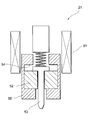
- FIG. 2 is a schematic diagram showing a schematic configuration of the fuel injection valve in FIG. 1.
- FIG. 3 is a diagram illustrating an example of a configuration of a drive circuit of the fuel injection valve.
- FIG. 4 is a functional block diagram of the ECU in FIG.
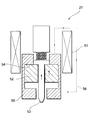
- FIG. 5 is a schematic diagram showing a valve opening state at the time of full lift injection of the fuel injection valve.
- FIG. 6 is a schematic diagram showing a valve opening state at the time of partial lift injection of the fuel injection valve.
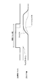
- FIG. 7 is a time chart showing injection pulses and lift amounts at the time of full lift injection and partial lift injection of the fuel injection valve.
- FIG. 1 is a diagram illustrating a schematic configuration of an engine control system to which an ECU (fuel injection control device) according to an embodiment of the present disclosure is applied.
- FIG. 2 is a schematic diagram
- FIG. 8 is a diagram showing the relationship between the injection pulse width of the fuel injection valve and the actual injection amount.
- FIG. 9 is a time chart for explaining the variation in the behavior of the drive voltage due to the influence of the magnetic circuit of the fuel injection valve.
- FIG. 10 is a diagram illustrating an example of the variation in the drive voltage behavior value calculated from the behavior of the minus terminal voltage illustrated in FIG. 9.
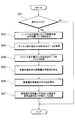
- FIG. 11 is a flowchart showing a magnetic circuit variation value calculation process performed by the ECU according to the present embodiment.
- FIG. 12 is a flowchart showing a flow of calculation processing of voltage inflection time, which is an example of the drive voltage behavior value.
- FIG. 13 is a time chart showing an execution example of voltage inflection time calculation.
- the engine control system 10 includes a direct injection engine 11 (hereinafter simply referred to as “engine 11”), which is an internal combustion engine of direct injection, and an electronic control unit (hereinafter referred to as “ECU”). And the ECU 30 controls the behavior of the engine 11.
- the engine 11 has a plurality of cylinders 40 such as an in-line four-cylinder engine having four cylinders 40, for example, but only a single cylinder 40 and a pipe system connected thereto are shown in FIG.
- An air cleaner 13 is provided at the most upstream portion of the intake pipe 12 of the engine 11, and an air flow meter 14 for detecting the intake air amount is provided downstream of the air cleaner 13.
- a throttle valve 16 whose opening is adjusted by a motor 15 and a throttle opening sensor 17 for detecting the opening (throttle opening) of the throttle valve 16 are provided on the downstream side of the air flow meter 14.
- a surge tank 18 is provided on the downstream side of the throttle valve 16, and an intake pipe pressure sensor 19 for detecting the intake pipe pressure is provided in the surge tank 18.
- the surge tank 18 is provided with an intake manifold 20 for introducing air into each cylinder 40 of the engine 11.
- the cylinder 40 includes a piston 40a and a cylinder 40b.
- Each cylinder 40 of the engine 11 is provided with a fuel injection valve 21 that directly injects fuel into the cylinder.
- An ignition plug 22 is attached to each cylinder 40 on the cylinder head 40c above the cylinder 40b, and the air-fuel mixture in the cylinder is ignited by spark discharge of the ignition plug 22 of each cylinder 40.
- the fuel injection valve 21 includes a drive coil 51, a plunger 52, a needle valve 53 (valve element), a stopper 54, and a fixed core 55.
- the fuel injection valve 21 is a known electromagnetically driven (solenoid type) injector.
- the fuel injection valve 21 is opened by driving the needle valve 53 in the valve opening direction integrally with the plunger 52 (movable core) by the electromagnetic force generated by the drive coil 51 when the drive coil 51 of the built-in solenoid is energized.
- the valve state is set so that fuel injection is performed.
- the fuel injection valve 21 returns to the valve closing position and the valve valve is closed, and the fuel injection is stopped. The details of the fuel injection control by the fuel injection valve 21 will be described later.
- the exhaust pipe 23 is connected to each cylinder 40 of the engine 11.
- the exhaust pipe 23 is provided with an exhaust gas sensor 24 (air-fuel ratio sensor, oxygen sensor, etc.) for detecting the air-fuel ratio or rich / lean of the exhaust gas, and the exhaust gas sensor 24 purifies the exhaust gas downstream of the exhaust gas sensor 24.
- a catalyst 25 such as an original catalyst is provided.
- a cooling water temperature sensor 26 for detecting the cooling water temperature and a knock sensor 27 for detecting knocking are attached to the cylinder 40b of the engine 11.
- a crankshaft 28 that converts the reciprocating motion of the piston 40a into a circular motion is connected to each piston 40a.
- a crank angle sensor 29 that outputs a pulse signal every time the crankshaft 28 rotates by a predetermined crank angle is attached to the outer peripheral side of the crankshaft 28. Based on the output signal of the crank angle sensor 29, the crank angle and the engine speed Is detected.
- the engine control system 10 is provided with an accelerator sensor 41 that detects an accelerator operation (an amount of depression of an accelerator pedal).
- the output signals from these various sensors are input to the ECU 30.
- the ECU 30 is mainly composed of a microcomputer, and executes various engine control programs stored in a built-in ROM (storage medium), so that the fuel injection amount and the ignition timing are determined according to the engine operating state.
- the throttle opening (intake air amount) and the like are controlled.
- the ECU 30 is provided with an engine control microcomputer 112 (a microcomputer for controlling the engine 11), an injector drive IC 113 (a drive IC for the fuel injection valve 21), and the like.
- the ECU 30 calculates the required injection amount according to the engine operating state (for example, engine speed, engine load, etc.) by the engine control microcomputer 112, and the required injection amount according to the required injection amount.
- the pulse width Ti is calculated.
- the injector drive IC 113 drives the fuel injection valve 21 to open with a required injection pulse width Ti corresponding to the required injection amount, and injects fuel for the required injection amount.
- the ECU 30 is also provided with a power supply IC 111 that supplies a constant voltage power supply to the microcomputer 112.
- the drive of the electromagnetically driven (solenoid) fuel injection valve 21 is controlled by controlling the energization of the drive coil 51 by the drive circuit 100 including the ECU 30. More specifically, the drive circuit 100 controls the energization start timing and energization time (in other words, energization end timing) to the drive coil 61, whereby the fuel injection amount and the fuel injection timing to each cylinder by the fuel injection valve 21 are controlled. Is controlled.
- the drive circuit 100 for the fuel injection valve 21 includes a battery 110, a power supply IC 111, an engine control microcomputer 112, and an injector drive IC 113.
- the battery 110 is a battery power supply unit that supplies power for energizing the drive coil 51 and power for driving the engine control microcomputer 112.
- the power supply IC 111 is a constant voltage power supply unit that supplies constant voltage power to the engine control microcomputer 112.
- the power supply IC 11 When the power supply IC 11 cannot supply a constant voltage to the engine control microcomputer 112, the power supply IC 11 outputs a reset signal for resetting the engine control microcomputer 112.
- the engine control microcomputer 112 is a control unit that outputs an injector drive signal to the injector drive IC 113.
- the engine control microcomputer 112 is configured to perform a reset operation when a reset signal is input from the power supply IC 11.
- the injector drive IC 113 is a control unit that controls energization of the drive coil 51 of the fuel injection valve 21 based on an injector drive signal input from the engine control microcomputer 112.
- the injector driving IC 113 switches the on / off of each switch by controlling the energization of the discharging switch 114, the constant current switch 115, the charging switch 119, and the cylinder selection switch 126, all of which are composed of MOS transistors. ing.
- the cylinder selection switch 126 has one output terminal (drain) connected to the other end of the drive coil 51 (on the downstream side in the energization path of the drive coil 51).
- a current detection resistor 127 is provided between the other output terminal (source) of the cylinder selection switch 126 and the ground line. The current detection resistor 127 detects a current (drive current) flowing through the drive coil 51 via the cylinder selection switch 126, and the voltage generated in the current detection resistor 127 is injector driven as a current detection signal IN1 indicating the detected current.
- a current detection signal IN1 indicating the detected current.
- the driving circuit 100 controlled by the injector driving IC 113 is further provided with diodes 121, 123, 124, 125, capacitors 117, 122, an inductor 118, and a resistor 120.
- the charging switch 119, the inductor 118, the resistor 120, and the diode 121 form a booster circuit that charges the capacitor 122 to a specified charging voltage.
- the inductor 118 has one end connected to a power supply to which the battery voltage VB is supplied and the other end connected to one output terminal (drain) of the charging switch 119.
- the other output terminal (source) of the charging switch 119 is grounded via a resistor 120.
- the gate terminal of the charging switch 119 is connected to the injector driving IC 113, and the charging switch 119 is turned on / off according to the output of the injector driving IC 113.
- one end (positive terminal) of the capacitor 122 is connected to a connection point between the inductor 118 and the charging switch 119 via a backflow prevention diode 121.
- the other end (negative electrode side terminal) of the capacitor 122 is grounded.
- the discharge switch 114 is for supplying a large current for opening the valve from the capacitor 122 to the drive coil 51.
- the discharge switch 114 is provided to discharge the electric energy charged in the capacitor 122 to the drive coil 51.
- the discharge switch 114 is turned on, the positive electrode side terminal (high voltage side terminal) of the capacitor 122 is electrically connected to one end side of the drive coil 51, thereby discharging the capacitor 122 from the drive coil 51. Be started.
- the discharge switch 114 and the capacitor 122 constitute a peak current drive circuit.
- the constant current switch 115 is for supplying a constant current (holding current) for holding the valve open state after the valve is opened to the drive coil 51.
- a constant current holding current
- the constant current switch 115 is turned on while the cylinder selection switch 126 is turned on, a current flows through the drive coil 51 from the power supply line through the backflow preventing diode 123.
- the diode 125 is a feedback diode for constant current control with respect to the drive coil 51.
- the constant current switch 115 is turned off while the cylinder selection switch 126 is turned on, a current is supplied to the drive coil 51. Reflux.
- the constant current switch 115, the diode 123, and the diode 125 constitute a constant current drive circuit.
- the engine control microcomputer 112 performs various controls for operating the engine 11.
- One of the controls is the generation / output of an injector drive signal.
- the engine control microcomputer 112 drives the injector for each cylinder 40 based on the operation information of the engine 11 detected by the above-described various sensors such as the engine speed, the accelerator opening, the engine water temperature, and the fuel pressure in the common rail.
- a signal is generated and output to the injector driving IC 113.
- the injector driving IC 113 is configured to detect the voltage of the power line from the power supply IC 11 that is a constant voltage power supply unit to the engine control microcomputer 112 as the determination voltage IN2.
- the injector driving IC 113 outputs a driving signal for turning off the constant current switch 115 when the determination voltage IN2 falls below a threshold voltage that is higher than the reset voltage by a predetermined voltage. Further, the injector driving IC 113 outputs a driving signal for turning off the constant current switch 115, and then the current detection signal IN1 indicating the current flowing through the driving coil 51 falls below the threshold current, and the determination voltage IN2 falls below the threshold voltage. If so, the off state of the constant current switch 115 is maintained.
- the injector driving IC 113 is configured to detect the voltage value (minus terminal voltage Vm) at the minus terminal 116 of the drive coil 51 of the fuel injection valve 21.
- the minus terminal 116 of the drive coil 51 is connected to the drive coil 51 side (drive coil) from the connection point between one output terminal (drain) of the cylinder selection switch 126 and the diode 124 in the drive circuit 100. 51 on the downstream side in the energization path 51.
- the opening operation of the electromagnetically driven fuel injection valve 21 will be described with reference to FIGS.
- the fuel injection valve 21 turns on the injection pulse and energizes the drive coil 51, as shown in FIGS. 5 and 6, the magnetism passing through the fixed core 55 and the plunger 52 (movable core) by energizing the drive coil 51.
- a circuit 56 is formed.
- an electromagnetic attractive force acts in the axial direction between the fixed core 55 and the plunger 52, and the needle valve 53 (valve element) is integrally opened with the plunger 52 by the electromagnetic attractive force (see FIG. 5). 6), the fuel injection valve 21 is opened.
- FIG. 7 shows (a) the injection pulse and (b) the lift amount as characteristics when the fuel injection valve 21 is driven to open.
- the needle valve 53 is opened with a lift amount corresponding to the injection pulse width.
- the ECU 30 executes full lift injection that opens the fuel injection valve 21 with an injection pulse in which the lift amount of the needle valve 53 reaches the full lift position in the full lift region, and the lift amount of the needle valve 53 is in the full lift position in the partial lift region. Partial lift injection is performed to open the fuel injection valve 21 with an injection pulse that reaches a partial lift state that does not reach.
- the fuel injection valve 21 of the in-cylinder injection engine 11 that injects high-pressure fuel into the cylinder has a linearity of the change characteristic of the actual injection amount with respect to the injection pulse width in the partial lift region (injection pulse width).
- injection pulse width the degree of the injection pulse width of the needle valve 53
- the variation in the lift amount of the needle valve 53 tends to increase between the individual fuel injection valves 21, and the variation in the injection amount tends to increase.
- the variation in the injection amount increases, the exhaust emission and drivability deteriorate. there's a possibility that.
- the negative terminal voltage Vm changes due to the induced electromotive force after the injection pulse is turned off (see FIG. 13).
- the change speed of the needle valve 53 changes relatively greatly, and the change characteristic of the negative terminal voltage Vm changes.
- the behavior of the drive voltage of the fuel injection valve 21 is affected by variations in the magnetic circuit 56 of the fuel injection valve 21 and varies among individuals.
- the “variation of the magnetic circuit 56” is an individual difference between the magnetic circuits 56 formed in the individual fuel injection valves 21.
- the fixed core 55 and the plunger 52 (movable core) in which the magnetic circuit 56 is formed This is due to the difference in the assembly state.
- Vm minus terminal voltage
- the magnetic circuit 56 is energized with a predetermined energization pulse in a range where the needle valve 53 of the fuel injection valve 21 is not driven, and the negative terminal at this time Variations in the magnetic circuit 56 are detected using the behavior of the voltage (drive voltage).
- FIG. 9 shows (A) drive current, (B) behavior of the armature (needle valve 53), and (C) time variation of the minus terminal voltage when an energization pulse is applied.
- 9 and 10 illustrate the behavior of three fuel injection valves, and those corresponding to each individual are represented by symbols a, b, and c.
- the horizontal axis in FIG. 10 is the valve closing timing
- the vertical axis is the driving voltage behavior value
- FIG. 10 shows the characteristics between the valve closing timing and the driving voltage behavior value.
- the standard relationship between the valve closing timing and the drive voltage behavior value is a proportional relationship.
- the “drive voltage behavior value” is a value derived from the behavior of the drive voltage such as the minus terminal voltage Vm (eg, time transition).
- the “driving voltage behavior value” an arbitrary index such as an index in units of time (eg, a differential value of the minus terminal voltage) or an index in units of voltage (eg, voltage difference from the reference at the time) is selected. can do.
- the driving voltage behavior value regarding the voltage inflection point at which the change characteristic of the minus terminal voltage Vm changes near the valve closing timing, the time from the predetermined reference timing to the timing at which the voltage inflection point occurs ( Voltage inflection point time Tdiff).
- Voltage inflection point time Tdiff the time from the predetermined reference timing to the timing at which the voltage inflection point occurs.
- the armature when energized by the predetermined injection pulse P1, the armature (needle valve 53) is driven in the valve opening direction as shown by the dotted line in FIG. 9B.
- the behavior of the negative terminal voltage at this time includes variations in the magnetic circuit, but the induced electromotive force due to the armature behavior is superimposed. For this reason, in the state where the fuel injection valve 21 is driven, the variation of the magnetic circuit 56 and the induced electromotive force cannot be separated, and the detection accuracy of the variation of the magnetic circuit may be lowered.
- the magnetic circuit 56 is energized with a predetermined “energization pulse” in a range where the needle valve 53 (valve element) of the fuel injection valve 21 is not driven.
- a predetermined “energization pulse” in a range where the needle valve 53 (valve element) of the fuel injection valve 21 is not driven.
- the energization pulse P2 has the same pulse width as the injection pulse P1, but the target current value is set smaller than the injection pulse P1.
- This energization pulse P2 inputs driving energy (current) to the extent that the valve body of the fuel injection valve 21 is not driven.
- the armature needle valve 53
- the driving voltage behavior value derived by using the negative terminal voltage behaviors a, b, and c detected in this way is also a value that strongly reflects the variation among the individual magnetic circuits 56, as shown in FIG.
- the difference between the drive voltage behavior values a, b, c derived from the drive voltages of the three fuel injectors becomes a magnetic circuit variation value (details will be described later) indicating the variation degree of the magnetic circuit 56 of each fuel injector. Equivalent to.
- the ECU 30 is a minus terminal for energizing the magnetic circuit 56 with a predetermined energization pulse in a range where the needle valve 53 (valve element) of the fuel injection valve 21 is not driven.
- Vm driving voltage
- a magnetic circuit variation value is calculated as information related to the minus terminal voltage Vm (driving voltage), and as information related to the valve closing timing Remember.
- variation between the individual fuel-injection valves 21 may be suppressed by correct
- ECU30 is provided with the injector control part 31 regarding each said function, the calculating part 32, the memory
- the injector control unit 31 and the calculation unit 32 are included in the injector driving IC 113, and the storage unit 33 and the injection pulse correction calculation unit 34 are included in the engine control microcomputer 112.
- the injector control unit 31 opens the fuel injection valve 21 by energizing the magnetic circuit 56 of the fuel injection valve 21 with a predetermined injection pulse. In addition, the injector control unit 31 energizes the magnetic circuit 56 with a predetermined energization pulse when acquiring time-series data of the minus terminal voltage Vm used for calculation of the drive voltage behavior value by the calculation unit 32.
- the calculation unit 32 calculates a drive voltage behavior value based on the minus terminal voltage Vm detected from the fuel injection valve 21 when the energization pulse is energized by the injector control unit 31, and uses the calculated drive voltage behavior value.
- the magnetic circuit variation value is calculated.
- the storage unit 33 stores the magnetic circuit variation value calculated by the calculation unit 32.
- the injection pulse correction calculation unit 34 performs correction calculation of the injection pulse applied to the fuel injection valve 21 using the magnetic circuit variation value stored in the storage unit 33. Specifically, the target pulse width Ti of the injection pulse (that is, the energization time of the fuel injection valve 21) is corrected according to the magnetic circuit variation value calculated for each fuel injection valve 21. The injector control unit 31 energizes each fuel injection valve in accordance with these corrected target pulse widths.
- the control flow shown in FIG. 11 is executed by the ECU 30 at predetermined intervals, for example.
- step S01 the injector control unit 31 checks whether or not the current engine operating state is during fuel cut.
- the injector control unit 31 can acquire information on the engine operating state from, for example, the engine control microcomputer 112 and use it for the determination. If the result of determination in step S01 is that the fuel is being cut (Yes in step S01), the current operation state of the vehicle is an operation state in which the fuel injection valve 21 is not driven. Proceed to step S02 to start. On the other hand, when the operating state is not during fuel cut (No in step S02), the present control flow ends.
- step S02 the injector controller 31 controls the target current value (for example, Cor_IP in FIG. 9A) and energization pulse width (for example, Cor_IP in FIG. 9A) based on the current operating state of the engine 11 to drive the needle valve 53 of the fuel injection valve 21.
- Cor_time in FIG. 9A is set. Only one of the target current value Cor_IP and the energization pulse width Cor_time may be set according to the operating state. For example, the target current value Cor_IP is set higher as the control fuel pressure of the engine 11 is higher, and is set lower as the control fuel pressure is lower.
- step S03 the energization control for energizing the magnetic circuit 56 with the energization pulse P2 including the target current value Cor_IP and the energization pulse width Cor_time set in step S02 is executed by the injector control unit 31, and the energization control is being performed by the calculation unit 32.
- the time series data of the minus terminal voltage Vm of each fuel injection valve 21 is acquired.
- the calculation unit 32 acquires the behavior of the negative terminal voltage Vm after the energization pulse P2 is cut (when switched to the off state).
- step S04 the time series data of the minus terminal voltage Vm acquired in step S03 is filtered by the calculation unit 32.
- the process of step S04 proceeds to step S05.
- step S05 the operation unit 32 calculates the drive voltage behavior value V_fb of each fuel injector 21 using the time series data of the minus terminal voltage Vm filtered in step S04.
- step S05 the process proceeds to step S06.
- step S06 an average value V_fb_Ave of the drive voltage behavior values V_fb of each fuel injection valve 21 calculated in step S05 is calculated.
- step S07 an average value V_fb_Ave of the drive voltage behavior values V_fb of each fuel injection valve 21 calculated in step S05 is calculated.
- step S07 the calculation unit 32 calculates the ratio between the drive voltage behavior value V_fb of each fuel injection valve 21 calculated in step S06 and the average value V_fb_Ave calculated in step S07.
- the value is stored in the storage unit 33 as a magnetic circuit variation value.
- the voltage inflection time which is an example of the drive voltage behavior value described above, will be described with reference to FIGS.
- the ECU 30 uses the calculation unit 32 of the injector driving IC 113 to set a first frequency f1 that is lower than the frequency of the noise component to the first terminal f1 that is lower than the noise component frequency after the energization pulse is turned off.
- the first filter voltage Vsm1 filtered by the low-pass filter (smoothing process) is calculated, and the negative terminal voltage Vm of the fuel injection valve 21 is set to the second frequency f2 lower than the first frequency f1 as the cutoff frequency.
- the process of calculating the second filter voltage Vsm2 filtered by the second low-pass filter (smoothing process) is performed for each cylinder of the engine 11. Thereby, the first filter voltage Vsm1 obtained by removing the noise component from the negative terminal voltage Vm and the second filter voltage Vsm2 for detecting the voltage inflection point can be calculated.
- the process of calculating the time until the timing becomes the voltage inflection time Tdiff is performed for each cylinder of the engine 11.
- the voltage inflection point time Tdiff is calculated using the timing at which the difference Vdiff exceeds a predetermined threshold value Vt as the timing at which the difference Vdiff becomes an inflection point.
- the time from the predetermined reference timing to the timing at which the difference Vdiff exceeds the predetermined threshold Vt is calculated as the voltage inflection time Tdiff.
- the voltage inflection point time Tdiff which changes according to the valve closing timing of the fuel injection valve 21 can be calculated with high accuracy.
- the voltage inflection point time Tdiff is calculated using the timing at which the energization pulse is switched from OFF to ON as the reference timing.
- the voltage inflection point time Tdiff can be calculated by, for example, a voltage inflection point time calculation routine shown in the flowchart of FIG. This routine can be executed in step S05 of the flowchart of FIG. 11 when the voltage inflection point time Tdiff is used as the drive voltage behavior value. That is, the voltage inflection time calculation routine of FIG. 12 is executed by the calculation unit 32 of the ECU 30.
- step S101 the minus terminal voltage Vm of the fuel injection valve 21 is acquired.
- the calculation cycle Ts of this routine becomes the sampling cycle Ts of the minus terminal voltage Vm.
- step S102 in which the negative terminal voltage Vm of the fuel injection valve 21 is a first low-pass filter whose cutoff frequency is a first frequency f1 lower than the frequency of the noise component (that is, lower than the cutoff frequency f1).
- a first filter voltage Vsm1 filtered by a low-pass filter having a frequency band as a pass band is calculated.
- the first low-pass filter obtains the current value Vsm1 (k) of the first filter voltage using the previous value Vsm1 (k-1) of the first filter voltage and the current value Vm (k) of the negative terminal voltage. It is a digital filter implemented by the following formula (1).
- Vsm1 (k) ⁇ (n1-1) / n1 ⁇ ⁇ Vsm1 (k ⁇ 1) + (1 / n1) ⁇ Vm (k) (1)
- step S103 the minus terminal voltage Vm of the fuel injection valve 21 is a second low-pass filter having a second frequency f2 lower than the first frequency f1 as a cut-off frequency (ie, lower than the cut-off frequency f2).
- a second filter voltage Vsm2 filtered by a low-pass filter having a low frequency band as a pass band is calculated.
- the second low-pass filter obtains the current value Vsm2 (k) of the second filter voltage using the previous value Vsm2 (k-1) of the second filter voltage and the current value Vm (k) of the minus terminal voltage.
- This is a digital filter implemented by the following equation (3).
- Vsm2 (k) ⁇ (n2-1) / n2 ⁇ ⁇ Vsm2 (k ⁇ 1) + (1 / n2) ⁇ Vm (k) (3)
- step S105 the threshold value Vt is acquired, and the previous value Tdiff (k ⁇ 1) of the voltage inflection time is acquired.
- the threshold value Vt is calculated according to the fuel pressure, fuel temperature, etc. by the engine control microcomputer 112, for example.
- the threshold value Vt may be a fixed value set in advance.
- step S106 it is determined whether or not it is the timing when the energization pulse is switched from OFF to ON. If it is determined in step S106 that it is time to switch the energization pulse from OFF to ON, the process proceeds to step S109, and the current value Tdiff (k) of the voltage inflection time is reset to “0”.
- step S106 determines whether the energization pulse is ON. If it is determined in step S107 that the energization pulse is on, the process proceeds to step S110, where the previous value Tdiff (k ⁇ 1) of the voltage inflection time is set to a predetermined value Ts (the calculation cycle of this routine). The current value Tdiff (k) of the voltage inflection time is obtained by addition to count up the voltage inflection time Tdiff.
- Tdiff (k) Tdiff (k ⁇ 1) + Ts
- the process proceeds to step S108, and the first filter voltage Vsm1 and the second filter voltage Vsm2 are set. It is determined whether or not the difference Vdiff has exceeded the threshold value Vt (whether or not the difference Vdiff has become smaller than the threshold value Vt).
- step S108 If it is determined in step S108 that the difference Vdiff between the first filter voltage Vsm1 and the second filter voltage Vsm2 has not yet exceeded the threshold value Vt, the process proceeds to step S110, where the voltage inflection time Tdiff is set. Continue counting up.
- step S108 if it is determined in step S108 that the difference Vdiff between the first filter voltage Vsm1 and the second filter voltage Vsm2 exceeds the threshold value Vt, it is determined that the calculation of the voltage inflection time Tdiff has been completed.
- step S111 the current value Tdiff (k) of the voltage inflection time is held at the previous value Tdiff (k-1).
- Tdiff (k) Tdiff (k-1)
- the first filter voltage Vsm1 obtained by filtering the minus terminal voltage Vm of the fuel injection valve 21 with the first low-pass filter is calculated, and the minus terminal voltage Vm of the fuel injection valve 21 is calculated as the second low-pass filter.
- the voltage inflection point time Tdiff is reset to “0”, and then the calculation of the voltage inflection point time Tdiff is started to perform a predetermined calculation. The process of counting up the voltage inflection time Tdiff with the cycle Ts is repeated.
- the calculated value of the voltage inflection time Tdiff is held until the next reference timing t3, and during this period (a period from the voltage inflection time Tdiff calculation completion timing t2 to the next reference timing t3), the engine control microcomputer 112 is used. Obtains the voltage inflection time Tdiff from the injector driving IC 113.
- the ECU 30 (fuel injection control device) according to the present embodiment energizes the magnetic circuit 56 with a predetermined energization pulse P2 within a range in which the needle valve 53 of the fuel injection valve 21 is not driven by the injector control unit 31.
- Information related to the behavior of the drive voltage (minus terminal voltage Vm) of the fuel injection valve 21 is stored in the storage unit 33.
- an induced electromotive force due to the armature behavior of the fuel injection valve 21 (the behavior of the needle valve 53) and variations due to individual differences of the magnetic circuit 56 are superimposed.
- the ECU 30 measures the behavior of the minus terminal voltage Vm pressure when the energization pulse is energized by the calculation unit 32, and based on the measured behavior of the minus terminal voltage Vm, the behavior of the drive voltage due to the influence of the magnetic circuit 56 is measured. A magnetic circuit variation value indicating the degree of variation is calculated, and this magnetic circuit variation value is stored in the storage unit 33 as information relating to the behavior of the drive voltage.
- the injector control unit 31 uses the injection pulse P1 corrected based on the magnetic circuit variation value stored in the storage unit 33 when the fuel injection valve 21 is driven to open.
- the injection pulse P1 is corrected based on variations due to individual differences in the magnetic circuit 56 of the fuel injection valve 21, and each fuel injection valve 21 is driven to open by the corrected injection pulse.
- the influence of variations due to individual differences in the magnetic circuit 56 can be reduced satisfactorily, and the control accuracy of the valve opening drive of each fuel injection valve 21 can be improved.
- the configuration in which the magnetic circuit variation value is stored in the storage unit as “information related to the behavior of the minus terminal voltage Vm (driving voltage)” is described.
- the information reflecting the behavior of the minus terminal voltage Vm is stored in the storage unit.
- the time series data of the minus terminal voltage Vm may be stored as it is, or from the time series data of the time minus terminal voltage such as the driving voltage behavior value (for example, the voltage inflection time Tdiff).
- the derived information may be stored.
- the driving state of the vehicle is in a fuel cut (see step S01 in FIG. 11).
- the current operation state may be an operation state in which the fuel injection valve 21 is not driven.
- the engine operation may be performed before the engine is started after the ignition is turned on.
- the ratio between the drive voltage behavior value V_fb of each fuel injector 21 and the average value V_fb_Ave of these behavior values is varied in the magnetic circuit.
- the configuration calculated as the value is illustrated (see step S07 in FIG. 11)
- any value that reflects the difference between the drive voltage behavior value V_fb of each fuel injection valve 21 and its average value V_fb_Ave may be used.
- the difference between the behavior value V ⁇ fb and the average value V_fb_Ave may be calculated as the magnetic circuit variation value.
- a reference value V_fb_base related to the drive voltage behavior is set, and a difference (ratio or difference) between the drive voltage behavior value V_fb of each fuel injection valve 21 and the reference value V_fb_base is calculated as a magnetic circuit variation value. It is good.
- the reference value V_fb_base may be a predetermined value set in advance, or may be calculated using a value obtained by processing the behavior of the measured drive voltage using a filter.
- the voltage value measured in other places such as the plus terminal voltage of the drive coil 51, may be used, for example. it can.
- the target current value Cor_IP and the energization pulse width Cor_time of the energization pulse P2 are set based on the current operating state of the engine 11. Although illustrated, the structure which makes these predetermined value may be sufficient.
- the injection pulse correction calculation unit 34 of the engine control microcomputer 112 determines the target of the injection pulse according to the magnetic circuit variation value for each fuel injection valve stored in the storage unit 33.
- the pulse width Ti that is, the energization time of each fuel injection valve 21
- the injector control unit 31 of the injector driving IC 113 energizes each fuel injection valve 21 in accordance with these corrected target pulse widths (that is, Although the configuration in which the energization time to the fuel injection valve is corrected based on the magnetic circuit variation value is illustrated, other methods may be used to correct the injection pulse.
- the detected value of the drive voltage such as the minus terminal voltage Vm measured when the fuel injector 21 is driven is corrected using the magnetic circuit variation value for each fuel injector stored in the storage unit 33, and the correction is performed.
- the ejection pulse may be set based on the detected value of the drive voltage.
Landscapes
- Engineering & Computer Science (AREA)
- Chemical & Material Sciences (AREA)
- Combustion & Propulsion (AREA)
- Mechanical Engineering (AREA)
- General Engineering & Computer Science (AREA)
- Physics & Mathematics (AREA)
- Electromagnetism (AREA)
- Electrical Control Of Air Or Fuel Supplied To Internal-Combustion Engine (AREA)
- Fuel-Injection Apparatus (AREA)
- Combined Controls Of Internal Combustion Engines (AREA)
Abstract
燃料噴射制御装置としてのECU(30)は、燃料噴射弁(21)の磁気回路(56)に所定の噴射パルス(P1)で通電を行うことで燃料噴射弁(21)を開弁駆動させると共に、燃料噴射弁(21)のニードル弁(53)が駆動しない範囲の所定の通電パルス(P2)で磁気回路(56)に通電を行うインジェクタ制御部(31)と、インジェクタ制御部(31)により磁気回路(56)に通電パルス(P2)で通電が行われるときの燃料噴射弁(21)の駆動電圧(マイナス端子電圧Vm)の挙動に係る情報を記憶する記憶部(33)と、を備える。
Description
本出願は、2015年4月24日に出願された日本特許出願番号2015-89305号に基づくもので、ここにその記載内容を援用する。
本開示は、内燃機関の燃料噴射制御装置に関する。
一般に、内燃機関の燃料噴射制御システムでは、電磁駆動式の燃料噴射弁を備え、内燃機関の運転状態に応じて要求噴射量を算出し、この要求噴射量に相当するパルス幅の噴射パルスで燃料噴射弁を開弁駆動して要求噴射量分の燃料を噴射するようにしている。
しかし、高圧の燃料を筒内に噴射する筒内噴射式の内燃機関の燃料噴射弁は、噴射パルス幅に対する実噴射量の変化特性の直線性がパーシャルリフト領域(噴射パルス幅が短くて弁体のリフト量がフルリフト位置に到達しないパーシャルリフト状態となる領域)で悪化する傾向がある。このパーシャルリフト領域では、弁体(例えばニードル弁、アーマチャ)のリフト量のばらつきが大きくなって噴射量ばらつきが大きくなる傾向があり、噴射量ばらつきが大きくなると、排気エミッションやドライバビリティが悪化する可能性がある。
燃料噴射弁の噴射量ばらつきの補正に関連する技術としては、例えば、特許文献1に記載されているように、ソレノイドの駆動電圧と、この駆動電圧をローパスフィルタでフィルタ処理したリファレンス電圧とを比較し、両者の交点に基づいてソレノイドのアーマチャ位置を検出するようにしたものなど、燃料噴射弁の駆動電圧(例えばマイナス端子電圧)の挙動に基づいてソレノイドのアーマチャ挙動を検出する技術がある。このような技術では、検出したアーマチャ挙動に基づいて燃料噴射弁の弁体のリフト量のばらつきを推定し、噴射量ばらつきの補正を行う。
しかし、燃料噴射弁の駆動電圧の挙動は燃料噴射弁の磁気回路の個体差の影響を受け、個体間で駆動電圧挙動にばらつきが発生するのが一般的である。駆動電圧の挙動に基づいてソレノイドのアーマチャ挙動(すなわち燃料噴射弁の弁体の挙動)の検出精度を向上させるために、燃料噴射弁の磁気回路の個体差の影響による駆動電圧挙動のばらつき度を精度良く検出できることが望ましい。
本開示は、燃料噴射弁の磁気回路の個体差の影響による駆動電圧挙動のばらつき度を精度よく検出できる内燃機関の燃料噴射制御装置を提供することを目的とする。
本開示に係る燃料噴射制御装置は、電磁駆動式の燃料噴射弁を備えた内燃機関の燃料噴射制御装置において、前記燃料噴射弁の磁気回路に所定の噴射パルスで通電を行うことで前記燃料噴射弁を開弁駆動させると共に、前記燃料噴射弁の弁体が駆動しない範囲の所定の通電パルスで前記磁気回路に通電を行う制御部と、前記制御部により前記磁気回路に前記通電パルスで通電が行われるときの前記燃料噴射弁の駆動電圧の挙動に係る情報を記憶する記憶部と、を備える。
この構成により、燃料噴射弁が非駆動状態のときの駆動電圧の挙動に係る情報を記憶することができるので、燃料噴射弁の弁体の挙動による誘導起電力の影響が低減され、かつ、磁気回路の個体差によるばらつき度の影響が強い情報を保持することができる。したがって、この情報を利用すれば、燃料噴射弁の磁気回路の個体差の影響による駆動電圧挙動のばらつき度を精度よく検出できる。
本開示によれば、燃料噴射弁の磁気回路の個体差の影響による駆動電圧挙動のばらつき度を精度よく検出できる内燃機関の燃料噴射制御装置を提供することができる。
以下、添付図面を参照しながら本開示の実施形態について説明する。説明の理解を容易にするため、各図面において同一の構成要素に対しては可能な限り同一の符号を付して、重複する説明は省略する。
図1~4を参照しながら、本開示の一実施形態に係るECU(燃料噴射制御装置)を適用したエンジン制御システム10について説明する。
エンジン制御システム10は、図1に示すように、筒内噴射式の内燃機関である筒内噴射式エンジン11(以下では単に「エンジン11」と表記する)と、電子制御ユニット(以下「ECU」と表記する)30を備え、エンジン11の挙動をECU30が制御するように構成されている。エンジン11は、例えば4つの気筒40を有する直列4気筒エンジンなどのように複数の気筒40を有するが、図1では単一の気筒40及びそれに繋がる管系のみが図示されている。
エンジン11の吸気管12の最上流部には、エアクリーナ13が設けられ、このエアクリーナ13の下流側に、吸入空気量を検出するエアフローメータ14が設けられている。このエアフローメータ14の下流側には、モータ15によって開度調節されるスロットルバルブ16と、このスロットルバルブ16の開度(スロットル開度)を検出するスロットル開度センサ17とが設けられている。
更に、スロットルバルブ16の下流側には、サージタンク18が設けられ、このサージタンク18に、吸気管圧力を検出する吸気管圧力センサ19が設けられている。また、サージタンク18には、エンジン11の各気筒40に空気を導入する吸気マニホールド20が設けられている。
気筒40は、ピストン40a及びシリンダ40bによって構成されている。エンジン11の各気筒40には、それぞれ筒内に燃料を直接噴射する燃料噴射弁21が取り付けられている。また、シリンダ40bの上方のシリンダヘッド40cには、各気筒40毎に点火プラグ22が取り付けられ、各気筒40の点火プラグ22の火花放電によって筒内の混合気に着火される。
燃料噴射弁21は、図2に示すように、駆動コイル51と、プランジャ52と、ニードル弁53(弁体)と、ストッパ54と、固定コア55とを有する。燃料噴射弁21は、周知の電磁駆動式(ソレノイド式)のインジェクタである。燃料噴射弁21は、内蔵されたソレノイドの駆動コイル51に通電されると、駆動コイル51によって生じる電磁力によってプランジャ52(可動コア)と一体的にニードル弁53を開弁方向に駆動して開弁状態となり燃料噴射が行われる構成となっている。燃料噴射弁21は、駆動コイル51への通電が停止されると、ニードル弁53が閉弁位置に戻って閉弁状態となり、燃料噴射が停止される。なお、燃料噴射弁21による燃料噴射制御の詳細については後述する。
エンジン11の各気筒40には排気管23が繋がれている。排気管23には、排出ガスの空燃比又はリッチ/リーン等を検出する排出ガスセンサ24(空燃比センサ、酸素センサ等)が設けられ、この排出ガスセンサ24の下流側に、排出ガスを浄化する三元触媒等の触媒25が設けられている。
また、エンジン11のシリンダ40bには、冷却水温を検出する冷却水温センサ26や、ノッキングを検出するノックセンサ27が取り付けられている。図1では図示を省略しているが、各ピストン40aには、ピストン40aの往復運動を円運動に変換するクランク軸28が連結されている。クランク軸28の外周側には、クランク軸28が所定クランク角回転する毎にパルス信号を出力するクランク角センサ29が取り付けられ、このクランク角センサ29の出力信号に基づいてクランク角やエンジン回転速度が検出される。エンジン制御システム10には、アクセル操作(アクセルペダルの踏込量)を検出するアクセルセンサ41が設けられている。
これら各種センサからの出力信号は、ECU30に入力される。このECU30は、マイクロコンピュータを主体として構成され、内蔵されたROM(記憶媒体)に記憶された各種のエンジン制御用のプログラムを実行することで、エンジン運転状態に応じて、燃料噴射量、点火時期、スロットル開度(吸入空気量)等を制御する。
図3,4に示すように、ECU30には、エンジン制御用マイコン112(エンジン11の制御用のマイクロコンピュータ)、インジェクタ駆動用IC113(燃料噴射弁21の駆動用IC)等が設けられている。ECU30は、図4に示すように、エンジン制御用マイコン112により、エンジン運転状態(例えばエンジン回転速度やエンジン負荷等)に応じて要求噴射量を算出して、この要求噴射量に応じて要求噴射パルス幅Ti(噴射時間)を算出する。そして、インジェクタ駆動用IC113により、要求噴射量に応じた要求噴射パルス幅Tiで燃料噴射弁21を開弁駆動して要求噴射量分の燃料を噴射する。また、ECU30には、図3に示すように、マイコン112に定電圧電源を供給する電源IC111も設けられている。
電磁駆動式(ソレノイド式)の燃料噴射弁21は、例えば図3に示すように、ECU30を含む駆動回路100によって駆動コイル51への通電が制御されることで、その駆動が制御されている。より詳細には、駆動回路100が駆動コイル61への通電開始タイミングおよび通電時間(換言すれば通電終了タイミング)を制御することにより、燃料噴射弁21による各気筒への燃料噴射量及び燃料噴射時期が制御されている。
図3に示されるように、燃料噴射弁21の駆動回路100は、バッテリ110と、電源IC111と、エンジン制御用マイコン112と、インジェクタ駆動用IC113と、を備えている。バッテリ110は、駆動コイル51に通電するための電力及びエンジン制御用マイコン112を駆動するための電力を供給するバッテリ電源部である。
電源IC111は、エンジン制御用マイコン112に定電圧電源を供給する定電圧電源部である。電源IC11は、エンジン制御用マイコン112に定電圧を供給できなくなると、エンジン制御用マイコン112をリセットするためのリセット信号を出力する。
エンジン制御用マイコン112は、インジェクタ駆動用IC113へインジェクタ駆動信号を出力する制御部である。エンジン制御用マイコン112は、電源IC11からリセット信号が入力されると、リセット動作を行うように構成されている。
インジェクタ駆動用IC113は、エンジン制御用マイコン112から入力されるインジェクタ駆動信号に基づいて、燃料噴射弁21の駆動コイル51への通電制御を行う制御部である。インジェクタ駆動用IC113は、いずれもMOSトランジスタで構成される放電用スイッチ114、定電流スイッチ115、充電用スイッチ119、及び気筒選択スイッチ126へ通電制御を行うことで、各スイッチのオン/オフを切り替えている。
気筒選択スイッチ126には、駆動コイル51の他端(駆動コイル51の通電経路における下流側)に一方の出力端子(ドレイン)が接続されている。気筒選択スイッチ126の他方の出力端子(ソース)とグランドラインとの間には、電流検出抵抗127が設けられている。電流検出抵抗127は、気筒選択スイッチ126を介して駆動コイル51に流れる電流(駆動電流)を検出するものであり、電流検出抵抗127に生じる電圧が、検出電流を示す電流検出信号IN1としてインジェクタ駆動用IC113へ入力される。
インジェクタ駆動用IC113が制御する駆動回路100には更に、ダイオード121,123,124,125と、コンデンサ117,122と、インダクタ118と、抵抗120と、が設けられている。充電用スイッチ119、インダクタ118、抵抗120、及びダイオード121は、コンデンサ122を規定充電電圧に充電する昇圧回路を形成している。
インダクタ118は、一端がバッテリ電圧VBの供給される電源に接続され、他端が充電用スイッチ119の一方の出力端子(ドレイン)に接続されている。充電用スイッチ119の他方の出力端子(ソース)は抵抗120を介して接地されている。充電用スイッチ119のゲート端子はインジェクタ駆動用IC113に接続されており、このインジェクタ駆動用IC113の出力に応じて充電用スイッチ119がオン/オフされる。
更に、インダクタ118と充電用スイッチ119との接続点に、逆流防止用のダイオード121を介してコンデンサ122の一端(正極側端子)が接続されている。そして、コンデンサ122の他端(負極側端子)は接地されている。
この昇圧回路においては、充電用スイッチ119がオン/オフされると、インダクタ118と充電用スイッチ119との接続点に、バッテリ電圧VBよりも高いフライバック電圧(逆起電圧)が発生し、そのフライバック電圧により、ダイオード121を通じてコンデンサ122が充電される。これにより、コンデンサ122がバッテリ電圧VBよりも高い電圧に充電される。コンデンサ122は、インジェクタ駆動用IC113によって、充電電圧が予め設定された規定充電電圧になるように制御される。
放電用スイッチ114は、コンデンサ122から駆動コイル51へ開弁のための大電流を供給するためのものである。放電用スイッチ114は、コンデンサ122に充電された電気エネルギーを駆動コイル51へ放電させるために設けられている。この放電用スイッチ114がオンされると、コンデンサ122の正極側端子(高電圧側の端子)が駆動コイル51の一端側に電気的に接続され、これによりコンデンサ122から駆動コイル51への放電が開始される。上述した昇圧回路に加えて、放電用スイッチ114及びコンデンサ122は、ピーク電流駆動回路を構成している。
定電流スイッチ115は、駆動コイル51へ、開弁後にその開弁状態を保持させるための一定の電流(保持電流)を流すためのものである。気筒選択スイッチ126がオンされている状態で定電流スイッチ115がオンされると、駆動コイル51に、電源ラインから逆流防止用のダイオード123を介して電流が流れる。尚、ダイオード125は、駆動コイル51に対する定電流制御のための帰還ダイオードであり、気筒選択スイッチ126がオンされている状態で定電流スイッチ115がオンからオフされた時に、駆動コイル51に電流を還流させるものである。定電流スイッチ115、ダイオード123、及びダイオード125は、定電流駆動回路を構成している。
エンジン制御用マイコン112は、エンジン11を動作させるための各種制御を行う。その制御の1つとしてインジェクタ駆動信号の生成・出力がある。エンジン制御用マイコン112は、エンジン回転数、アクセル開度、エンジン水温、コモンレール内の燃料圧力など、上述の各種センサにて検出されるエンジン11の運転情報に基づいて、各気筒40毎のインジェクタ駆動信号を生成し、インジェクタ駆動用IC113へ出力する。
インジェクタ駆動用IC113は、定電圧電源部である電源IC11からエンジン制御用マイコン112に至る電力線の電圧を判定用電圧IN2として検知するように構成されている。インジェクタ駆動用IC113は、判定用電圧IN2がリセット電圧よりよりも所定電圧分高い閾値電圧を下回った場合に、定電流スイッチ115をオフする駆動信号を出力する。また、インジェクタ駆動用IC113は、定電流スイッチ115をオフする駆動信号の出力後、駆動コイル51に流れる電流を示す電流検出信号IN1が閾値電流を下回り、且つ判定用電圧IN2が閾値電圧を下回っている場合には、定電流スイッチ115のオフ状態を維持する。
本実施形態では、インジェクタ駆動用IC113は、燃料噴射弁21の駆動コイル51のマイナス端子116における電圧値(マイナス端子電圧Vm)を検知するよう構成されている。駆動コイル51のマイナス端子116は、図3に示すように、駆動回路100において、気筒選択スイッチ126の一方の出力端子(ドレイン)と、ダイオード124との接続点より、駆動コイル51側(駆動コイル51の通電経路における下流側)に配置される。
ここで、図2、5~7を参照して、電磁駆動式の燃料噴射弁21の開弁動作について説明する。燃料噴射弁21は、噴射パルスをオンして駆動コイル51に通電したときに、図5,6に示すように、駆動コイル51への通電により固定コア55及びプランジャ52(可動コア)を通る磁気回路56が形成される。この磁気回路56によって固定コア55とプランジャ52との間で軸方向に電磁吸引力が作用し、電磁吸引力によりプランジャ52と一体的にニードル弁53(弁体)が開弁方向(図5,6の紙面上方向)に駆動することで、燃料噴射弁21が開弁状態となる。
燃料噴射弁21の開弁状態は、噴射パルスの噴射パルス幅に応じて、図5に示すフルリフト領域と、図6に示すパーシャルリフト領域とに区分される。図7には、燃料噴射弁21の開弁駆動時の特性として、(a)噴射パルス、及び(b)リフト量が示される。図7に示すように、燃料噴射弁21では、所定の電流値及び噴射パルス幅の噴射パルスによって通電されると、噴射パルス幅に応じたリフト量でニードル弁53が開弁される。
図7に実線で示すように噴射パルス幅が比較的長くなるフルリフト領域では、図5に示すように、ニードル弁53のリフト量がフルリフト位置(プランジャ52がストッパ54に突き当たる位置)に到達する。一方、図7に点線で示すように、噴射パルス幅が比較的短くなるパーシャルリフト領域では、図6に示すように、ニードル弁53のリフト量がフルリフト位置に到達しないパーシャルリフト状態(プランジャ52がストッパ54に突き当たる手前の状態)となる。
ECU30は、フルリフト領域ではニードル弁53のリフト量がフルリフト位置に到達する噴射パルスで燃料噴射弁21を開弁駆動するフルリフト噴射を実行し、パーシャルリフト領域ではニードル弁53のリフト量がフルリフト位置に到達しないパーシャルリフト状態となる噴射パルスで燃料噴射弁21を開弁駆動するパーシャルリフト噴射を実行する。
高圧の燃料を筒内に噴射する筒内噴射式エンジン11の燃料噴射弁21は、図8に示すように、噴射パルス幅に対する実噴射量の変化特性の直線性がパーシャルリフト領域(噴射パルス幅が短くてニードル弁53のリフト量がフルリフト位置に到達しないパーシャルリフト状態となる領域)で悪化する傾向がある。このパーシャルリフト領域では、燃料噴射弁21の個体間でニードル弁53のリフト量のばらつきが大きくなって噴射量ばらつきが大きくなる傾向があり、噴射量ばらつきが大きくなると、排気エミッションやドライバビリティが悪化する可能性がある。
燃料噴射弁21は、噴射パルスのオフ後に誘導起電力によってマイナス端子電圧Vmが変化する(図13参照)。その際、燃料噴射弁21が閉弁するときに、ニードル弁53の変化速度(プランジャ52の変化速度)が比較的大きく変化して、マイナス端子電圧Vmの変化特性が変化するため、閉弁タイミング付近でマイナス端子電圧Vmの変化特性が変化する電圧変曲点となる。つまり、燃料噴射弁21の閉弁タイミング付近のマイナス端子電圧Vmの変化特性は、燃料噴射弁21の閉弁タイミングと相関があると考えられる。また、燃料噴射弁21の閉弁タイミングと実際の燃料噴射量にも相関がある。したがって、マイナス端子電圧Vm(駆動電圧)の挙動を観測することで、燃料噴射弁21のアーマチャ挙動(すなわち、ニードル弁53のリフト量の挙動)や、閉弁タイミング、燃料噴射量を精度良く推定できると考えられる。
燃料噴射弁21の駆動電圧の挙動は、燃料噴射弁21の磁気回路56のばらつきの影響を受け、個体間でばらつきが発生するのが一般的である。ここで「磁気回路56のばらつき」とは、個々の燃料噴射弁21に形成される磁気回路56の個体差であり、例えば、磁気回路56が形成される固定コア55とプランジャ52(可動コア)との組み付け状態の差異などに起因するものである。このため、マイナス端子電圧Vm(駆動電圧)を用いた燃料噴射弁の挙動の検出精度を向上するために、燃料噴射弁21の個体間の磁気回路56のばらつきを精度良く検出することが望ましい。
しかし、燃料噴射弁21の開弁駆動中における駆動電圧の挙動には、燃料噴射弁21のアーマチャ挙動(ニードル弁53の挙動)による誘導起電力が重畳する。このため、燃料噴射弁が駆動している状態では、磁気回路のばらつきとソレノイドのアーマチャ挙動による誘導起電力量の切り分けができず、駆動電圧の挙動から磁気回路ばらつきを精度良く検出することが難しい場合がある。
そこで本実施形態では、通常の開弁駆動時に用いる噴射パルスの代わりに、燃料噴射弁21のニードル弁53が駆動しない範囲の所定の通電パルスで磁気回路56に通電を行い、このときのマイナス端子電圧(駆動電圧)の挙動を用いて磁気回路56のばらつきを検出している。
ここで、図9,10を参照して、本実施形態における磁気回路のばらつきの検出手法についてさらに説明する。図9には、通電パルス印加時の(A)駆動電流、(B)アーマチャ(ニードル弁53)の挙動、(C)マイナス端子電圧の時間変化が示されている。図9,10では、3つの燃料噴射弁の挙動が例示されており、各個体に対応するものを符号a,b,cで表している。図10の横軸は閉弁タイミング、縦軸は駆動電圧挙動値であり、図10は閉弁タイミングと駆動電圧挙動値との間の特性を示している。図10に直線のグラフで示すように、閉弁タイミングと駆動電圧挙動値との標準的な関係は比例関係となる。ここで、「駆動電圧挙動値」は、マイナス端子電圧Vmなどの駆動電圧の挙動(例えば時間推移)から導出される値である。
「駆動電圧挙動値」としては、時間を単位とする指標(例えばマイナス端子電圧の微分値など)や、電圧を単位とする指標(例えば時点における基準との電圧差)などの任意の指標を選択することができる。駆動電圧挙動値の一例として、閉弁タイミング付近でマイナス端子電圧Vmの変化特性が変化する上記の電圧変曲点に関して、所定の基準タイミングからのこの電圧変曲点が発生するタイミングまでの時間(電圧変曲点時間Tdiff)が挙げられる。ここでは、まず一般的な概念として「駆動電圧挙動値」という用語を用いて説明し、電圧変曲点時間Tdiffの詳細な説明については、図12,13を参照して後述する。
図9(A)に点線で示すように、所定の噴射パルスP1によって通電されると、図9(B)に点線で示すように、アーマチャ(ニードル弁53)が開弁方向に駆動する。このときのマイナス端子電圧の挙動は、磁気回路のばらつきを含むが、アーマチャ挙動による誘導起電力が重畳する。このため、燃料噴射弁21を駆動している状態では、磁気回路56のばらつきと誘導起電力量の切り分けができず、磁気回路のばらつきの検出精度が低くなる虞がある。
これに対して、本実施形態では、燃料噴射弁21のニードル弁53(弁体)が駆動しない範囲の所定の「通電パルス」で磁気回路56に通電を行う。通電パルスP2は、例えば図9(A)に実線で示すように、パルス幅は噴射パルスP1と同様であるが、目標電流値が噴射パルスP1より小さく設定されている。この通電パルスP2は、燃料噴射弁21の弁体が駆動しない程度の駆動エネルギー(電流)を投入する。これにより、図9(B)に実線で示すように、通電中にもアーマチャ(ニードル弁53)は駆動しないので、図9(C)に3つの燃料噴射弁におけるマイナス端子電圧の挙動a,b,cの差異は、アーマチャの挙動の影響が無い状態で検出される。このため、個々の燃料噴射弁21における磁気回路56のばらつきの影響が強い挙動を検出できる。このように検出されたマイナス端子電圧の挙動a,b,cを用いて導出される駆動電圧挙動値も磁気回路56の個体間のばらつきを強く反映させた値となり、図10に示すように、3つの燃料噴射弁の駆動電圧から導出された駆動電圧挙動値a,b,cの間の差分が、各燃料噴射弁の磁気回路56のばらつき度を示す磁気回路ばらつき値(詳細は後述)に相当する。
このような特性に着目して、本実施形態では、ECU30は、燃料噴射弁21のニードル弁53(弁体)が駆動しない範囲の所定の通電パルスで磁気回路56に通電を行うときのマイナス端子電圧Vm(駆動電圧)を計測し、計測したマイナス端子電圧の挙動を用いて、マイナス端子電圧Vm(駆動電圧)に係る情報として磁気回路ばらつき値を算出して、閉弁タイミングに関連する情報として記憶する。そして、この磁気回路ばらつき値に基づいてパーシャルリフト噴射の噴射パルスを補正することで、燃料噴射弁21の個体間の噴射量ばらつきを抑制するよう構成されている。
ECU30は、図4に示すように、上記の各機能に関するインジェクタ制御部31と、演算部32と、記憶部33と、噴射パルス補正演算部34とを備える。インジェクタ制御部31と演算部32とは、インジェクタ駆動用IC113に含まれ、記憶部33と噴射パルス補正演算部34とはエンジン制御用マイコン112に含まれる。
インジェクタ制御部31は、燃料噴射弁21の磁気回路56に所定の噴射パルスで通電を行うことで燃料噴射弁21を開弁駆動する。また、インジェクタ制御部31は、演算部32による駆動電圧挙動値の算出に用いるマイナス端子電圧Vmの時系列データを取得する際に、所定の通電パルスで磁気回路56に通電を行う。
演算部32は、インジェクタ制御部31により通電パルスが通電された際の燃料噴射弁21から検出されるマイナス端子電圧Vmに基づいて駆動電圧挙動値を算出し、算出した駆動電圧挙動値を用いて磁気回路ばらつき値を算出する。
記憶部33は、演算部32により算出された磁気回路ばらつき値を記憶する。
噴射パルス補正演算部34は、記憶部33に記憶されている磁気回路ばらつき値を用いて、燃料噴射弁21に印加する噴射パルスの補正演算を行う。具体的には、燃料噴射弁21ごとに算出された磁気回路ばらつき値に応じて、噴射パルスの目標パルス幅Ti(すなわち燃料噴射弁21の通電時間)を補正する。インジェクタ制御部31は、これらの補正された目標パルス幅にしたがって各燃料噴射弁に通電を行う。
磁気回路ばらつき値の算出処理の詳細について、図11のフローチャートを参照して説明する。図11に示す制御フローは、ECU30により例えば所定周期ごとに実行される。
ステップS01では、インジェクタ制御部31により、現在のエンジンの運転状態が燃料カット中か否かが確認される。インジェクタ制御部31は、例えばエンジン制御用マイコン112からエンジンの運転状態の情報を取得し、判定に利用することができる。ステップS01の判定の結果、燃料カット中である場合(ステップS01のYes)には、車両の現在の運転状態が燃料噴射弁21を駆動しない運転状態であるため、磁気回路ばらつき値の算出処理を開始すべくステップS02に進む。一方、運転状態が燃料カット中でない場合(ステップS02のNo)には本制御フローを終了する。
ステップS02では、インジェクタ制御部31により、現在のエンジン11の運転状態に基づき、燃料噴射弁21のニードル弁53が駆動しない目標電流値(例えば図9(A)のCor_IP)及び通電パルス幅(例えば図9(A)のCor_time)が設定される。なお、目標電流値Cor_IP及び通電パルス幅Cor_timeの一方のみを運転状態に応じて設定してもよい。目標電流値Cor_IPは、例えば、エンジン11の制御燃圧が高いほど高く設定され、前記制御燃圧が低いほど低く設定される。ステップS02の処理が完了するとステップS03へ移行する。
ステップS03では、インジェクタ制御部31により、ステップS02で設定した目標電流値Cor_IP及び通電パルス幅Cor_timeからなる通電パルスP2で磁気回路56に通電させる通電制御が実行され、演算部32により、通電制御中の各燃料噴射弁21のマイナス端子電圧Vmの時系列データが取得される。演算部32は、例えば、通電パルスP2のカット時(オフ状態に切り替わったとき)以降のマイナス端子電圧Vmの挙動を取得する。ステップS03の処理が完了するとステップS04へ移行する。
ステップS04では、演算部32により、ステップS03で取得したマイナス端子電圧Vmの時系列データがフィルタ処理される。ステップS04の処理が完了するとステップS05へ移行する。
ステップS05では、演算部32により、ステップS04にてフィルタ処理されたマイナス端子電圧Vmの時系列データを用いて、各燃料噴射弁21の駆動電圧挙動値V_fbが算出される。ステップS05の処理が完了するとステップS06へ移行する。
ステップS06では、ステップS05で算出された各燃料噴射弁21の駆動電圧挙動値V_fbの平均値V_fb_Aveが算出される。ステップS06の処理が完了するとステップS07へ移行する。
ステップS07では、演算部32により、ステップS06で算出された各燃料噴射弁21の駆動電圧挙動値V_fbと、ステップS07で算出されたこれらの平均値V_fb_Aveとの割合が算出され、この算出値が磁気回路ばらつき値として記憶部33に記憶される。ステップS07の処理が完了すると本制御フローを終了する。
図12及び図13を参照して、上述した駆動電圧挙動値の一例である電圧変曲点時間について説明する。
ECU30は、インジェクタ駆動用IC113の演算部32で、通電パルスのオフ後に、燃料噴射弁21のマイナス端子電圧Vmをノイズ成分の周波数よりも低い第1の周波数f1をカットオフ周波数とする第1のローパスフィルタでフィルタ処理(なまし処理)した第1のフィルタ電圧Vsm1を算出すると共に、燃料噴射弁21のマイナス端子電圧Vmを第1の周波数f1よりも低い第2の周波数f2をカットオフ周波数とする第2のローパスフィルタでフィルタ処理(なまし処理)した第2のフィルタ電圧Vsm2を算出する処理をエンジン11の各気筒毎に行う。これにより、マイナス端子電圧Vmからノイズ成分を除去した第1のフィルタ電圧Vsm1と電圧変曲点検出用の第2のフィルタ電圧Vsm2を算出することができる。
更に、インジェクタ駆動用IC113の演算部32で、第1のフィルタ電圧Vsm1と第2のフィルタ電圧Vsm2との差分Vdiff(=Vsm1-Vsm2)を算出し、所定の基準タイミングから差分Vdiffが変曲点となるタイミングまでの時間を電圧変曲点時間Tdiffとして算出する処理をエンジン11の各気筒毎に行う。この際、本実施形態では、差分Vdiffが所定の閾値Vtを越えるタイミングを、差分Vdiffが変曲点となるタイミングとして電圧変曲点時間Tdiffを算出する。つまり、所定の基準タイミングから差分Vdiffが所定の閾値Vtを越えるタイミングまでの時間を電圧変曲点時間Tdiffとして算出する。これにより、燃料噴射弁21の閉弁タイミングに応じて変化する電圧変曲点時間Tdiffを精度良く算出することができる。本実施形態では、通電パルスがオフからオンに切り換わるタイミングを基準タイミングとして電圧変曲点時間Tdiffを算出する。
電圧変曲点時間Tdiffは、例えば図12のフローチャートに示す電圧変曲点時間算出ルーチンにより算出することができる。このルーチンは、駆動電圧挙動値として電圧変曲点時間Tdiffを用いる場合に、図11のフローチャートのステップS05において実施することができる。つまり、図12の電圧変曲点時間算出ルーチンは、ECU30の演算部32により実行される。
まず、ステップS101で、燃料噴射弁21のマイナス端子電圧Vmを取得する。この場合、本ルーチンの演算周期Tsがマイナス端子電圧Vmのサンプリング周期Tsとなる。
この後、ステップS102に進み、燃料噴射弁21のマイナス端子電圧Vmをノイズ成分の周波数よりも低い第1の周波数f1をカットオフ周波数とする第1のローパスフィルタ(つまりカットオフ周波数f1よりも低い周波数帯域を通過域とするローパスフィルタ)でフィルタ処理した第1のフィルタ電圧Vsm1を算出する。
第1のローパスフィルタは、第1のフィルタ電圧の前回値Vsm1(k-1)とマイナス端子電圧の今回値Vm(k)とを用いて第1のフィルタ電圧の今回値Vsm1(k)を求める下記(1)式で実装されるデジタルフィルタである。
Vsm1(k)={(n1-1)/n1}×Vsm1(k-1)+(1/n1)×Vm(k)…(1)
この第1のローパスフィルタの時定数n1は、マイナス端子電圧Vmのサンプリング周波数fs(=1/Ts )と第1のローパスフィルタのカットオフ周波数f1とを用いた下記(2)式の関係を満たすように設定されている。
この第1のローパスフィルタの時定数n1は、マイナス端子電圧Vmのサンプリング周波数fs(=1/Ts )と第1のローパスフィルタのカットオフ周波数f1とを用いた下記(2)式の関係を満たすように設定されている。
1/fs:1/f1=1:(n1-1)…(2)
これにより、ノイズ成分の周波数よりも低い第1の周波数f1をカットオフ周波数とする第1のローパスフィルタでフィルタ処理した第1のフィルタ電圧Vsm1を容易に算出することができる。
これにより、ノイズ成分の周波数よりも低い第1の周波数f1をカットオフ周波数とする第1のローパスフィルタでフィルタ処理した第1のフィルタ電圧Vsm1を容易に算出することができる。
この後、ステップS103に進み、燃料噴射弁21のマイナス端子電圧Vmを第1の周波数f1よりも低い第2の周波数f2をカットオフ周波数とする第2のローパスフィルタ(つまりカットオフ周波数f2よりも低い周波数帯域を通過域とするローパスフィルタ)でフィルタ処理した第2のフィルタ電圧Vsm2を算出する。
第2のローパスフィルタは、第2のフィルタ電圧の前回値Vsm2(k-1)とマイナス端子電圧の今回値Vm(k)とを用いて第2のフィルタ電圧の今回値Vsm2(k)を求める下記(3)式で実装されるデジタルフィルタである。
Vsm2(k)={(n2-1)/n2}×Vsm2(k-1)+(1/n2)×Vm(k)…(3)
この第2のローパスフィルタの時定数n2は、マイナス端子電圧Vmのサンプリング周波数fs(=1/Ts)と第2のローパスフィルタのカットオフ周波数f2とを用いた下記(4)式の関係を満たすように設定されている。
この第2のローパスフィルタの時定数n2は、マイナス端子電圧Vmのサンプリング周波数fs(=1/Ts)と第2のローパスフィルタのカットオフ周波数f2とを用いた下記(4)式の関係を満たすように設定されている。
1/fs:1/f2=1:(n2-1)…(4)
これにより、第1の周波数f1よりも低い第2の周波数f2をカットオフ周波数とする第2のローパスフィルタでフィルタ処理した第2のフィルタ電圧Vsm2を容易に算出することができる。
これにより、第1の周波数f1よりも低い第2の周波数f2をカットオフ周波数とする第2のローパスフィルタでフィルタ処理した第2のフィルタ電圧Vsm2を容易に算出することができる。
この後、ステップS104に進み、第1のフィルタ電圧Vsm1と第2のフィルタ電圧Vsm2との差分Vdiff(=Vsm1-Vsm2)を算出する。尚、この差分Vdiffが0以上にならないようにガード処理して、マイナス成分だけを抽出するようにしても良い。
この後、ステップS105に進み、閾値Vtを取得すると共に、電圧変曲点時間の前回値Tdiff(k-1)を取得する。閾値Vtは、例えばエンジン制御用マイコン112により燃圧や燃温等に応じて算出される。あるいは、閾値Vtを予め設定した固定値としても良い。
この後、ステップS106に進み、通電パルスがオフからオンに切り換わるタイミングであるか否かを判定する。このステップS106で、通電パルスがオフからオンに切り換わるタイミングであると判定された場合には、ステップS109に進み、電圧変曲点時間の今回値Tdiff(k)を「0」にリセットする。
Tdiff(k)=0
一方、上記ステップS106で、通電パルスがオフからオンに切り換わるタイミングではないと判定された場合には、ステップS107に進み、通電パルスがオンであるか否かを判定する。このステップS107で、通電パルスがオンであると判定された場合には、ステップS110に進み、電圧変曲点時間の前回値Tdiff(k-1)に所定値Ts(本ルーチンの演算周期)を加算して電圧変曲点時間の今回値Tdiff(k)を求めることで、電圧変曲点時間Tdiffをカウントアップする。
一方、上記ステップS106で、通電パルスがオフからオンに切り換わるタイミングではないと判定された場合には、ステップS107に進み、通電パルスがオンであるか否かを判定する。このステップS107で、通電パルスがオンであると判定された場合には、ステップS110に進み、電圧変曲点時間の前回値Tdiff(k-1)に所定値Ts(本ルーチンの演算周期)を加算して電圧変曲点時間の今回値Tdiff(k)を求めることで、電圧変曲点時間Tdiffをカウントアップする。
Tdiff(k)=Tdiff(k-1)+Ts
その後、上記ステップS107で、通電パルスがオンではない(つまり通電パルスがオフである)と判定された場合には、ステップS108に進み、第1のフィルタ電圧Vsm1と第2のフィルタ電圧Vsm2との差分Vdiffが閾値Vtを越えたか否か(閾値Vtよりも小から大になったか否か)を判定する。
その後、上記ステップS107で、通電パルスがオンではない(つまり通電パルスがオフである)と判定された場合には、ステップS108に進み、第1のフィルタ電圧Vsm1と第2のフィルタ電圧Vsm2との差分Vdiffが閾値Vtを越えたか否か(閾値Vtよりも小から大になったか否か)を判定する。
このステップS108で、第1のフィルタ電圧Vsm1と第2のフィルタ電圧Vsm2との差分Vdiffがまだ閾値Vtを越えていないと判定された場合には、ステップS110に進み、電圧変曲点時間Tdiffをカウントアップする処理を継続する。
その後、上記ステップS108で、第1のフィルタ電圧Vsm1と第2のフィルタ電圧Vsm2との差分Vdiffが閾値Vtを越えたと判定された場合には、電圧変曲点時間Tdiffの算出が完了したと判断して、ステップS111に進み、電圧変曲点時間の今回値Tdiff(k)を前回値Tdiff(k-1)に保持する。
Tdiff(k)=Tdiff(k-1)
これにより、通電パルスがオフからオンに切り換わるタイミング(基準タイミング)から差分Vdiffが閾値Vtを越えるタイミングまでの時間を電圧変曲点時間Tdiffとして算出し、この電圧変曲点時間Tdiffの算出値を次の基準タイミングまで保持する。このようにして電圧変曲点時間Tdiffを算出する処理をエンジン11の各気筒毎に行う。
これにより、通電パルスがオフからオンに切り換わるタイミング(基準タイミング)から差分Vdiffが閾値Vtを越えるタイミングまでの時間を電圧変曲点時間Tdiffとして算出し、この電圧変曲点時間Tdiffの算出値を次の基準タイミングまで保持する。このようにして電圧変曲点時間Tdiffを算出する処理をエンジン11の各気筒毎に行う。
図13のタイムチャートを用いて本実施形態の電圧変曲点時間算出の実行例を説明する。
通電パルスのオフ後に、燃料噴射弁21のマイナス端子電圧Vmを第1のローパスフィルタでフィルタ処理した第1のフィルタ電圧Vsm1を算出すると共に、燃料噴射弁21のマイナス端子電圧Vmを第2のローパスフィルタでフィルタ処理した第2のフィルタ電圧Vsm2を算出する。更に、第1のフィルタ電圧Vsm1と第2のフィルタ電圧Vsm2との差分Vdiff(=Vsm1-Vsm2)を算出する。
そして、通電パルスがオフからオンに切り換わるタイミング(基準タイミング)t1で、電圧変曲点時間Tdiffを「0」にリセットした後、電圧変曲点時間Tdiffの算出を開始して、所定の演算周期Tsで電圧変曲点時間Tdiffをカウントアップする処理を繰り返す。
その後、通電パルスのオフ後に第1のフィルタ電圧Vsm1と第2のフィルタ電圧Vsm2との差分Vdiffが閾値Vtを越えるタイミングt2で、電圧変曲点時間Tdiffの算出を完了する。これにより、通電パルスがオフからオンに切り換わるタイミング(基準タイミング)t1から差分Vdiffが閾値Vtを越えるタイミングt2までの時間を電圧変曲点時間Tdiffとして算出する。
この電圧変曲点時間Tdiffの算出値を次の基準タイミングt3まで保持し、この間(電圧変曲点時間Tdiffの算出完了タイミングt2から次の基準タイミングt3までの期間)に、エンジン制御用マイコン112が電圧変曲点時間Tdiffをインジェクタ駆動用IC113から取得する。
本実施形態に係るECU30(燃料噴射制御装置)は、インジェクタ制御部31により、燃料噴射弁21のニードル弁53が駆動しない範囲の所定の通電パルスP2で磁気回路56に通電を行い、このときの燃料噴射弁21の駆動電圧(マイナス端子電圧Vm)の挙動に係る情報(本実施形態では磁気回路ばらつき値)を記憶部33に記憶する。燃料噴射弁21の駆動時の駆動電圧には、燃料噴射弁21のアーマチャ挙動(ニードル弁53の挙動)による誘導起電力と、磁気回路56の個体差によるばらつきとが重畳されている。上記構成により、燃料噴射弁21が非駆動状態のときの駆動電圧の挙動に係る情報を記憶することができるので、燃料噴射弁21のアーマチャ挙動による誘導起電力の影響が低減され、かつ、磁気回路56の個体差によるばらつき度の影響が強い情報を保持することができる。したがって、この情報を利用すれば、燃料噴射弁21の磁気回路56の個体差の影響による駆動電圧挙動のばらつき度を精度よく検出できる。
また、ECU30は、演算部32により、通電パルスの通電時のマイナス端子電圧Vm圧の挙動を計測し、計測したマイナス端子電圧Vmの挙動に基づいて、磁気回路56の影響による駆動電圧の挙動のばらつき度を示す磁気回路ばらつき値を算出し、この磁気回路ばらつき値を駆動電圧の挙動に係る情報として記憶部33に記憶する。インジェクタ制御部31は、燃料噴射弁21を開弁駆動させる際に、記憶部33に記憶される磁気回路ばらつき値に基づいて補正された噴射パルスP1を用いる。この構成により、燃料噴射弁21の磁気回路56の個体差によるばらつきに基づき噴射パルスP1を補正し、補正した噴射パルスによって各燃料噴射弁21の開弁駆動を行うので、各燃料噴射弁21の磁気回路56の個体差によるばらつきの影響を良好に低減でき、各燃料噴射弁21の開弁駆動の制御精度を向上できる。
以上、具体例を参照しつつ本開示の実施の形態について説明した。しかし、本開示はこれらの具体例に限定されるものではない。すなわち、これら具体例に、当業者が適宜設計変更を加えたものも、本開示の特徴を備えている限り、本開示の範囲に包含される。例えば、前述した各具体例が備える各要素及びその配置、材料、条件、形状、サイズなどは、例示したものに限定されるわけではなく適宜変更することができる。また、前述した各実施の形態が備える各要素は、技術的に可能な限りにおいて組み合わせることができ、これらを組み合わせたものも本開示の特徴を含む限り本開示の範囲に包含される。
上記実施形態では、「マイナス端子電圧Vm(駆動電圧)の挙動に係る情報」として磁気回路ばらつき値を記憶部に記憶する構成を例示したが、マイナス端子電圧Vmの挙動を反映する情報を記憶部に記憶すればよく、例えば、マイナス端子電圧Vmの時系列データをそのまま記憶してもよいし、上記の駆動電圧挙動値(例えば電圧変曲点時間Tdiff)など時マイナス端子電圧の時系列データから導出される情報を記憶する構成としてもよい。
上記実施形態では、図11のフローチャートに示す磁気回路ばらつき値の算出処理を実施する条件として、車両の運転状態が燃料カット中であることを例示したが(図11のステップS01参照)、車両の現在の運転状態が燃料噴射弁21を駆動しない運転状態であればよく、例えばイグニッションオン後のエンジン始動前に実施する構成としてもよい。また、燃料噴射弁21が駆動される運転状態のときに磁気回路ばらつき値の算出処理を実施する構成とすることもできる。
また、上記実施形態では、図11のフローチャートに示す磁気回路ばらつき値の算出処理において、各燃料噴射弁21の駆動電圧挙動値V_fbと、これらの挙動値の平均値V_fb_Aveとの割合を磁気回路ばらつき値として算出する構成を例示したが(図11のステップS07参照)、各燃料噴射弁21の駆動電圧挙動値V_fbとその平均値V_fb_Aveとの差異を反映させる値であればよく、例えば各駆動電圧挙動値V¥fbと平均値V_fb_Aveとの差分を磁気回路ばらつき値として算出する構成でもよい。
同様に、駆動電圧の挙動に係る基準値V_fb_baseを設定し、各燃料噴射弁21の駆動電圧挙動値V_fbと、この基準値V_fb_baseとの差異(割合や差分)を磁気回路ばらつき値として算出する構成としてもよい。この場合、基準値V_fb_baseは、予め設定される所定値でもよいし、計測した駆動電圧の挙動をフィルタによって加工したものを用いて算出する構成としてもよい。
また、上記実施形態では、燃料噴射弁21の駆動電圧としてマイナス端子電圧Vmを計測する構成を例示したが、例えば駆動コイル51のプラス端子電圧など他の箇所で計測される電圧値を用いることもできる。
また、上記実施形態では、図11のフローチャートに示す磁気回路ばらつき値の算出処理において、現在のエンジン11の運転状態に基づいて通電パルスP2の目標電流値Cor_IP及び通電パルス幅Cor_timeを設定する構成を例示したが、これらを所定値とする構成でもよい。
また、上記実施形態では、ECU30において、エンジン制御用マイコン112の噴射パルス補正演算部34が、記憶部33に記憶されている各燃料噴射弁ごとの磁気回路ばらつき値に応じて、噴射パルスの目標パルス幅Ti(すなわち各燃料噴射弁21の通電時間)を補正し、インジェクタ駆動用IC113のインジェクタ制御部31が、これらの補正された目標パルス幅にしたがって各燃料噴射弁21に通電を行う(すなわち磁気回路ばらつき値に基づいて燃料噴射弁への通電時間を補正する)構成を例示したが、噴射パルスの補正は他の手法でもよい。例えば、燃料噴射弁21の駆動時に計測されるマイナス端子電圧Vmなどの駆動電圧の検出値を、記憶部33に記憶されている各燃料噴射弁ごとの磁気回路ばらつき値を用いて補正し、補正された駆動電圧の検出値に基づいて噴射パルスを設定する構成としてもよい。
本開示は、実施例に準拠して記述されたが、本開示は当該実施例や構造に限定されるものではないと理解される。本開示は、様々な変形例や均等範囲内の変形をも包含する。加えて、様々な組み合わせや形態、さらには、それらに一要素のみ、それ以上、あるいはそれ以下、を含む他の組み合わせや形態をも、本開示の範疇や思想範囲に入るものである。
Claims (20)
- 電磁駆動式の燃料噴射弁(21)を備えた内燃機関(11)の燃料噴射制御装置(30)において、
前記燃料噴射弁の磁気回路(56)に所定の噴射パルス(P1)で通電を行うことで前記燃料噴射弁を開弁駆動させると共に、前記燃料噴射弁の弁体(53)が駆動しない範囲の所定の通電パルス(P2)で前記磁気回路に通電を行う制御部(31)と、
前記制御部により前記磁気回路に前記通電パルスで通電が行われるときの前記燃料噴射弁の駆動電圧の挙動に係る情報を記憶する記憶部(33)と、を備える内燃機関の燃料噴射制御装置。 - 前記制御部により前記磁気回路に前記通電パルスで通電が行われるときの前記燃料噴射弁の駆動電圧の挙動を計測し、前記計測した駆動電圧の挙動に基づいて、前記磁気回路の影響による前記挙動のばらつき度を示す磁気回路ばらつき値を算出する演算部(32)を備え、
前記記憶部は、演算部により算出された前記磁気回路ばらつき値を前記駆動電圧の挙動に係る前記情報として記憶し、
前記制御部は、前記燃料噴射弁を開弁駆動させる際に、前記記憶部に記憶される前記磁気回路ばらつき値に基づいて補正された前記噴射パルスを用いる請求項1に記載の内燃機関の燃料噴射制御装置。 - 前記駆動電圧の挙動に係る前記情報は、前記計測した駆動電圧の前記挙動から算出される駆動電圧挙動値(V_fb)と、前記内燃機関に備えられる複数の前記燃料噴射弁の個々の前記駆動電圧挙動値の平均値(V_fb_Ave)との差異を含む請求項1または2に記載の内燃機関の燃料噴射制御装置。
- 前記駆動電圧の挙動に係る前記情報は、前記計測した駆動電圧の前記挙動から算出される駆動電圧挙動値と、前記駆動電圧の挙動に係る基準値(V_fb_base)との差異を含む請求項1または2に記載の内燃機関の燃料噴射制御装置。
- 前記基準値は、予め設定される請求項4に記載の内燃機関の燃料噴射制御装置。
- 前記基準値は、前記計測した前記駆動電圧の前記挙動をフィルタによって加工したものを用いて算出される請求項4に記載の内燃機関の燃料噴射制御装置。
- 前記差異とは両者間の割合である請求項3~6のいずれか1項に記載の内燃機関の燃料噴射制御装置。
- 前記差異とは両者間の差分である請求項3~6のいずれか1項に記載の内燃機関の燃料噴射制御装置。
- 前記駆動電圧は、前記燃料噴射弁のマイナス端子電圧(Vm)である請求項1~8のいずれか1項に記載の内燃機関の燃料噴射制御装置。
- 前記駆動電圧挙動値は、時間を単位とする指標である請求項3~8のいずれか1項に記載の内燃機関の燃料噴射制御装置。
- 前記駆動電圧挙動値は、電圧を単位とする指標である請求項3~8のいずれか1項に記載の内燃機関の燃料噴射制御装置。
- 前記通電パルスは、目標電流値(Cor_IP)または通電パルス幅(Cor_time)を調整して前記燃料噴射弁の前記弁体が駆動しない範囲に設定される請求項1~11のいずれか1項に記載の内燃機関の燃料噴射制御装置。
- 前記通電パルスの前記目標電流値及び前記通電パルス幅の少なくとも一方は、前記内燃機関の運転状態に応じて変更される請求項12に記載の内燃機関の燃料噴射制御装置。
- 前記通電パルスの前記目標電流値は、前記内燃機関の制御燃圧が高いほど高く設定され、前記制御燃圧が低いほど低く設定される請求項13に記載の内燃機関の燃料噴射制御装置。
- 前記制御部は、前記燃料噴射弁が燃料噴射を実施しない運転領域のとき、前記通電パルスで前記磁気回路に通電を行う請求項1~14のいずれか1項に記載の内燃機関の燃料噴射制御装置。
- 前記制御部は、前記内燃機関の始動前に、前記通電パルスで前記磁気回路に通電を行う請求項15に記載の内燃機関の燃料噴射制御装置。
- 前記制御部は、前記内燃機関の作動中の燃料カット運転中に、前記通電パルスで前記磁気回路に通電を行う請求項15に記載の内燃機関の燃料噴射制御装置。
- 前記駆動電圧の挙動に係る前記情報は、前記制御部により前記磁気回路に前記通電パルスで通電が行われるときの前記駆動電圧がフィルタによってなまされたものから算出される請求項1~17のいずれか1項に記載の内燃機関の燃料噴射制御装置。
- 前記制御部は、前記燃料噴射弁を開弁駆動させる際に、前記記憶部に記憶される前記駆動電圧の挙動に係る前記情報に基づいて、前記燃料噴射弁への通電時間を補正する請求項1~18のいずれか1項に記載の内燃機関の燃料噴射制御装置。
- 前記制御部は、前記燃料噴射弁を開弁駆動させる際に、前記記憶部に記憶される前記駆動電圧の挙動に係る前記情報に基づいて、前記駆動電圧の検出値を補正し、前記補正された検出値に基づき前記噴射パルスを設定する請求項1~18のいずれか1項に記載の内燃機関の燃料噴射制御装置。
Priority Applications (3)
| Application Number | Priority Date | Filing Date | Title |
|---|---|---|---|
| US15/568,248 US10125730B2 (en) | 2015-04-24 | 2016-03-30 | Fuel injection control device for internal combustion engine |
| CN201680022589.2A CN107849997B (zh) | 2015-04-24 | 2016-03-30 | 内燃机的燃料喷射控制装置 |
| DE112016001897.5T DE112016001897B4 (de) | 2015-04-24 | 2016-03-30 | Kraftstoffeinspritzsteuerungsvorrichtung für eine Verbrennungskraftmaschine |
Applications Claiming Priority (2)
| Application Number | Priority Date | Filing Date | Title |
|---|---|---|---|
| JP2015-089305 | 2015-04-24 | ||
| JP2015089305A JP6358163B2 (ja) | 2015-04-24 | 2015-04-24 | 内燃機関の燃料噴射制御装置 |
Publications (1)
| Publication Number | Publication Date |
|---|---|
| WO2016170738A1 true WO2016170738A1 (ja) | 2016-10-27 |
Family
ID=57143069
Family Applications (1)
| Application Number | Title | Priority Date | Filing Date |
|---|---|---|---|
| PCT/JP2016/001829 Ceased WO2016170738A1 (ja) | 2015-04-24 | 2016-03-30 | 内燃機関の燃料噴射制御装置 |
Country Status (5)
| Country | Link |
|---|---|
| US (1) | US10125730B2 (ja) |
| JP (1) | JP6358163B2 (ja) |
| CN (1) | CN107849997B (ja) |
| DE (1) | DE112016001897B4 (ja) |
| WO (1) | WO2016170738A1 (ja) |
Cited By (1)
| Publication number | Priority date | Publication date | Assignee | Title |
|---|---|---|---|---|
| JP2016205276A (ja) * | 2015-04-24 | 2016-12-08 | 株式会社デンソー | 内燃機関の燃料噴射制御装置 |
Families Citing this family (9)
| Publication number | Priority date | Publication date | Assignee | Title |
|---|---|---|---|---|
| EP3670880A1 (en) * | 2014-11-19 | 2020-06-24 | Hitachi Automotive Systems, Ltd. | Drive device for fuel injection device |
| JP6402749B2 (ja) * | 2016-07-27 | 2018-10-10 | トヨタ自動車株式会社 | 内燃機関の燃料噴射制御装置 |
| JP7000720B2 (ja) * | 2017-07-14 | 2022-01-19 | 株式会社デンソー | 内燃機関の燃料噴射制御装置 |
| JP6953862B2 (ja) * | 2017-07-26 | 2021-10-27 | 株式会社デンソー | 燃料噴射制御装置 |
| JP7035759B2 (ja) * | 2018-04-23 | 2022-03-15 | 株式会社デンソー | 燃料噴射弁の制御装置およびその方法 |
| JP2021085379A (ja) * | 2019-11-28 | 2021-06-03 | 株式会社デンソー | 噴射制御装置 |
| JP7283418B2 (ja) | 2020-02-25 | 2023-05-30 | 株式会社デンソー | 内燃機関の燃料噴射制御装置 |
| DE102022205308A1 (de) * | 2022-05-27 | 2023-11-30 | Hitachi Astemo, Ltd. | Steuerungsvorrichtung und Verfahren zur Steuerung eines lnjektors |
| CN119758768A (zh) * | 2024-12-27 | 2025-04-04 | 卓品智能科技无锡股份有限公司 | 甲醇发动机控制器的硬件在环仿真测试系统 |
Citations (10)
| Publication number | Priority date | Publication date | Assignee | Title |
|---|---|---|---|---|
| US5861746A (en) * | 1995-11-03 | 1999-01-19 | Motorola Inc. | Method for detecting closure of a solenoid coil from the rise time of each of the current peaks of the solenoid coil |
| US20030071613A1 (en) * | 2001-10-12 | 2003-04-17 | Schultz Wolfgang Ernst | Method and circuit for detecting the armature position of an electromagnet |
| JP2006077627A (ja) * | 2004-09-08 | 2006-03-23 | Denso Corp | 燃料噴射装置 |
| JP2006342692A (ja) * | 2005-06-08 | 2006-12-21 | Nippon Soken Inc | 燃料噴射制御方法、燃料噴射弁及び燃料噴射制御装置 |
| US7595971B2 (en) * | 2005-06-15 | 2009-09-29 | Honeywell International Inc. | Sensing armature motion in high-speed solenoids |
| JP2010073705A (ja) * | 2008-09-16 | 2010-04-02 | Mikuni Corp | プランジャ位置検出装置及び電磁弁 |
| JP2011184012A (ja) * | 2010-03-11 | 2011-09-22 | Hitachi Automotive Systems Ltd | 液圧制御装置 |
| WO2013073111A1 (ja) * | 2011-11-18 | 2013-05-23 | 株式会社デンソー | 内燃機関の燃料噴射制御装置 |
| WO2014174916A1 (ja) * | 2013-04-26 | 2014-10-30 | 日立オートモティブシステムズ株式会社 | 電磁弁の制御装置及びそれを用いた内燃機関の制御装置 |
| JP2015063928A (ja) * | 2013-09-25 | 2015-04-09 | 日立オートモティブシステムズ株式会社 | 燃料噴射装置の駆動装置 |
Family Cites Families (7)
| Publication number | Priority date | Publication date | Assignee | Title |
|---|---|---|---|---|
| DE102009018289B3 (de) * | 2009-04-21 | 2010-06-17 | Continental Automotive Gmbh | Verfahren und Vorrichtung zum Betreiben eines Einspritzventils |
| DE102010027806B4 (de) * | 2010-04-15 | 2024-01-18 | Robert Bosch Gmbh | Verfahren zum Betreiben einer Brennkraftmaschine, bei dem eine Größe ermittelt wird |
| JP5851354B2 (ja) | 2012-06-21 | 2016-02-03 | 日立オートモティブシステムズ株式会社 | 内燃機関の制御装置 |
| JP5831481B2 (ja) | 2013-03-25 | 2015-12-09 | 株式会社デンソー | 車両用電子装置 |
| DE102013205518B4 (de) * | 2013-03-27 | 2023-08-10 | Vitesco Technologies GmbH | Ermittlung des Zeitpunkts eines vorbestimmten Öffnungszustandes eines Kraftstoffinjektors |
| DE102013214412B4 (de) * | 2013-07-24 | 2016-03-31 | Continental Automotive Gmbh | Ermittlung des Zeitpunkts eines vorbestimmten Öffnungszustandes eines Kraftstoffinjektors |
| JP6358163B2 (ja) | 2015-04-24 | 2018-07-18 | 株式会社デンソー | 内燃機関の燃料噴射制御装置 |
-
2015
- 2015-04-24 JP JP2015089305A patent/JP6358163B2/ja active Active
-
2016
- 2016-03-30 US US15/568,248 patent/US10125730B2/en active Active
- 2016-03-30 DE DE112016001897.5T patent/DE112016001897B4/de active Active
- 2016-03-30 CN CN201680022589.2A patent/CN107849997B/zh active Active
- 2016-03-30 WO PCT/JP2016/001829 patent/WO2016170738A1/ja not_active Ceased
Patent Citations (10)
| Publication number | Priority date | Publication date | Assignee | Title |
|---|---|---|---|---|
| US5861746A (en) * | 1995-11-03 | 1999-01-19 | Motorola Inc. | Method for detecting closure of a solenoid coil from the rise time of each of the current peaks of the solenoid coil |
| US20030071613A1 (en) * | 2001-10-12 | 2003-04-17 | Schultz Wolfgang Ernst | Method and circuit for detecting the armature position of an electromagnet |
| JP2006077627A (ja) * | 2004-09-08 | 2006-03-23 | Denso Corp | 燃料噴射装置 |
| JP2006342692A (ja) * | 2005-06-08 | 2006-12-21 | Nippon Soken Inc | 燃料噴射制御方法、燃料噴射弁及び燃料噴射制御装置 |
| US7595971B2 (en) * | 2005-06-15 | 2009-09-29 | Honeywell International Inc. | Sensing armature motion in high-speed solenoids |
| JP2010073705A (ja) * | 2008-09-16 | 2010-04-02 | Mikuni Corp | プランジャ位置検出装置及び電磁弁 |
| JP2011184012A (ja) * | 2010-03-11 | 2011-09-22 | Hitachi Automotive Systems Ltd | 液圧制御装置 |
| WO2013073111A1 (ja) * | 2011-11-18 | 2013-05-23 | 株式会社デンソー | 内燃機関の燃料噴射制御装置 |
| WO2014174916A1 (ja) * | 2013-04-26 | 2014-10-30 | 日立オートモティブシステムズ株式会社 | 電磁弁の制御装置及びそれを用いた内燃機関の制御装置 |
| JP2015063928A (ja) * | 2013-09-25 | 2015-04-09 | 日立オートモティブシステムズ株式会社 | 燃料噴射装置の駆動装置 |
Cited By (1)
| Publication number | Priority date | Publication date | Assignee | Title |
|---|---|---|---|---|
| JP2016205276A (ja) * | 2015-04-24 | 2016-12-08 | 株式会社デンソー | 内燃機関の燃料噴射制御装置 |
Also Published As
| Publication number | Publication date |
|---|---|
| DE112016001897T5 (de) | 2018-01-04 |
| US10125730B2 (en) | 2018-11-13 |
| JP6358163B2 (ja) | 2018-07-18 |
| US20180149124A1 (en) | 2018-05-31 |
| CN107849997B (zh) | 2021-08-13 |
| JP2016205276A (ja) | 2016-12-08 |
| CN107849997A (zh) | 2018-03-27 |
| DE112016001897B4 (de) | 2022-10-13 |
Similar Documents
| Publication | Publication Date | Title |
|---|---|---|
| JP6358163B2 (ja) | 内燃機関の燃料噴射制御装置 | |
| JP6260501B2 (ja) | 内燃機関の燃料噴射制御装置 | |
| JP6156307B2 (ja) | 内燃機関の燃料噴射制御装置 | |
| JP6307971B2 (ja) | 燃料噴射制御装置 | |
| CN103946522B (zh) | 内燃机的燃料喷射控制设备 | |
| JP6070502B2 (ja) | 内燃機関の燃料噴射制御装置 | |
| JP6477321B2 (ja) | 内燃機関の燃料噴射制御装置 | |
| CN106795826B (zh) | 内燃机的控制装置 | |
| JP6304156B2 (ja) | 内燃機関の燃料噴射制御装置 | |
| WO2017051707A1 (ja) | 内燃機関の燃料噴射制御装置 | |
| WO2016170739A1 (ja) | 燃料噴射制御装置 | |
| JP7006155B2 (ja) | 燃料噴射制御装置 | |
| WO2018221527A1 (ja) | 内燃機関の燃料噴射制御装置 | |
| JP6953862B2 (ja) | 燃料噴射制御装置 | |
| JP6035583B2 (ja) | 内燃機関の燃料噴射制御装置 | |
| JP7000720B2 (ja) | 内燃機関の燃料噴射制御装置 |
Legal Events
| Date | Code | Title | Description |
|---|---|---|---|
| 121 | Ep: the epo has been informed by wipo that ep was designated in this application |
Ref document number: 16782766 Country of ref document: EP Kind code of ref document: A1 |
|
| WWE | Wipo information: entry into national phase |
Ref document number: 15568248 Country of ref document: US |
|
| WWE | Wipo information: entry into national phase |
Ref document number: 112016001897 Country of ref document: DE |
|
| 122 | Ep: pct application non-entry in european phase |
Ref document number: 16782766 Country of ref document: EP Kind code of ref document: A1 |