WO2016170714A1 - Hdd保持装置、hddユニットおよび情報処理装置 - Google Patents
Hdd保持装置、hddユニットおよび情報処理装置 Download PDFInfo
- Publication number
- WO2016170714A1 WO2016170714A1 PCT/JP2016/000552 JP2016000552W WO2016170714A1 WO 2016170714 A1 WO2016170714 A1 WO 2016170714A1 JP 2016000552 W JP2016000552 W JP 2016000552W WO 2016170714 A1 WO2016170714 A1 WO 2016170714A1
- Authority
- WO
- WIPO (PCT)
- Prior art keywords
- hdd
- unit
- holding device
- buffer member
- buffer
- Prior art date
- Legal status (The legal status is an assumption and is not a legal conclusion. Google has not performed a legal analysis and makes no representation as to the accuracy of the status listed.)
- Ceased
Links
Images





Classifications
-
- G—PHYSICS
- G11—INFORMATION STORAGE
- G11B—INFORMATION STORAGE BASED ON RELATIVE MOVEMENT BETWEEN RECORD CARRIER AND TRANSDUCER
- G11B33/00—Constructional parts, details or accessories not provided for in the other groups of this subclass
- G11B33/02—Cabinets; Cases; Stands; Disposition of apparatus therein or thereon
- G11B33/08—Insulation or absorption of undesired vibrations or sounds
-
- F—MECHANICAL ENGINEERING; LIGHTING; HEATING; WEAPONS; BLASTING
- F16—ENGINEERING ELEMENTS AND UNITS; GENERAL MEASURES FOR PRODUCING AND MAINTAINING EFFECTIVE FUNCTIONING OF MACHINES OR INSTALLATIONS; THERMAL INSULATION IN GENERAL
- F16F—SPRINGS; SHOCK-ABSORBERS; MEANS FOR DAMPING VIBRATION
- F16F1/00—Springs
- F16F1/36—Springs made of rubber or other material having high internal friction, e.g. thermoplastic elastomers
- F16F1/373—Springs made of rubber or other material having high internal friction, e.g. thermoplastic elastomers characterised by having a particular shape
- F16F1/376—Springs made of rubber or other material having high internal friction, e.g. thermoplastic elastomers characterised by having a particular shape having projections, studs, serrations or the like on at least one surface
-
- F—MECHANICAL ENGINEERING; LIGHTING; HEATING; WEAPONS; BLASTING
- F16—ENGINEERING ELEMENTS AND UNITS; GENERAL MEASURES FOR PRODUCING AND MAINTAINING EFFECTIVE FUNCTIONING OF MACHINES OR INSTALLATIONS; THERMAL INSULATION IN GENERAL
- F16F—SPRINGS; SHOCK-ABSORBERS; MEANS FOR DAMPING VIBRATION
- F16F15/00—Suppression of vibrations in systems; Means or arrangements for avoiding or reducing out-of-balance forces, e.g. due to motion
- F16F15/02—Suppression of vibrations of non-rotating, e.g. reciprocating systems; Suppression of vibrations of rotating systems by use of members not moving with the rotating systems
- F16F15/04—Suppression of vibrations of non-rotating, e.g. reciprocating systems; Suppression of vibrations of rotating systems by use of members not moving with the rotating systems using elastic means
- F16F15/08—Suppression of vibrations of non-rotating, e.g. reciprocating systems; Suppression of vibrations of rotating systems by use of members not moving with the rotating systems using elastic means with rubber springs ; with springs made of rubber and metal
-
- F—MECHANICAL ENGINEERING; LIGHTING; HEATING; WEAPONS; BLASTING
- F16—ENGINEERING ELEMENTS AND UNITS; GENERAL MEASURES FOR PRODUCING AND MAINTAINING EFFECTIVE FUNCTIONING OF MACHINES OR INSTALLATIONS; THERMAL INSULATION IN GENERAL
- F16F—SPRINGS; SHOCK-ABSORBERS; MEANS FOR DAMPING VIBRATION
- F16F7/00—Vibration-dampers; Shock-absorbers
-
- G—PHYSICS
- G06—COMPUTING OR CALCULATING; COUNTING
- G06F—ELECTRIC DIGITAL DATA PROCESSING
- G06F1/00—Details not covered by groups G06F3/00 - G06F13/00 and G06F21/00
- G06F1/16—Constructional details or arrangements
- G06F1/1601—Constructional details related to the housing of computer displays, e.g. of CRT monitors, of flat displays
-
- G—PHYSICS
- G06—COMPUTING OR CALCULATING; COUNTING
- G06F—ELECTRIC DIGITAL DATA PROCESSING
- G06F1/00—Details not covered by groups G06F3/00 - G06F13/00 and G06F21/00
- G06F1/16—Constructional details or arrangements
- G06F1/18—Packaging or power distribution
- G06F1/183—Internal mounting support structures, e.g. for supporting printed circuit boards
- G06F1/187—Mounting of fixed or removable disk drives
-
- G—PHYSICS
- G11—INFORMATION STORAGE
- G11B—INFORMATION STORAGE BASED ON RELATIVE MOVEMENT BETWEEN RECORD CARRIER AND TRANSDUCER
- G11B33/00—Constructional parts, details or accessories not provided for in the other groups of this subclass
- G11B33/12—Disposition of constructional parts in the apparatus, e.g. of power supply, of modules
- G11B33/121—Disposition of constructional parts in the apparatus, e.g. of power supply, of modules the apparatus comprising a single recording/reproducing device
- G11B33/123—Mounting arrangements of constructional parts onto a chassis
- G11B33/124—Mounting arrangements of constructional parts onto a chassis of the single recording/reproducing device, e.g. disk drive, onto a chassis
-
- F—MECHANICAL ENGINEERING; LIGHTING; HEATING; WEAPONS; BLASTING
- F16—ENGINEERING ELEMENTS AND UNITS; GENERAL MEASURES FOR PRODUCING AND MAINTAINING EFFECTIVE FUNCTIONING OF MACHINES OR INSTALLATIONS; THERMAL INSULATION IN GENERAL
- F16F—SPRINGS; SHOCK-ABSORBERS; MEANS FOR DAMPING VIBRATION
- F16F1/00—Springs
- F16F1/36—Springs made of rubber or other material having high internal friction, e.g. thermoplastic elastomers
- F16F1/373—Springs made of rubber or other material having high internal friction, e.g. thermoplastic elastomers characterised by having a particular shape
- F16F1/3732—Springs made of rubber or other material having high internal friction, e.g. thermoplastic elastomers characterised by having a particular shape having an annular or the like shape, e.g. grommet-type resilient mountings
Definitions
- the present invention relates to an HDD holding device for holding an HDD, an HDD holding device, an HDD unit having an HDD, and an information processing device having the HDD unit.
- an HDD holding apparatus that holds the HDD may be used in order to facilitate attachment / detachment work.
- An HDD unit is configured by a combination of the HDD holding device and the HDD held by the HDD holding device. The HDD unit is detachably mounted on the information processing apparatus.
- HDDs generally have an impact absorbing function.
- An HDD holding device having a shock absorbing action is disclosed in, for example, Patent Document 1.
- the HDD holding device disclosed in Patent Document 1 includes a reinforcing material to which the HDD is attached and a support member that supports the reinforcing material to which the HDD is attached via four buffer members.
- the mounting shaft directions of the four buffer members are all arranged along the height direction of the HDD holding device.
- some information processing apparatuses such as POS terminal apparatuses have a base part and a display part attached to the base part so as to be tiltable.
- the HDD unit When an HDD unit is mounted on a tiltable display unit in such an information processing apparatus, the HDD unit also assumes various angles in the display unit as the display unit is tilted.
- the buffer member in the HDD holding device includes a shock absorbing function only in one of the three axial directions and a shock absorbing function in a plurality of directions.
- the buffer member having the shock absorbing action in a plurality of directions does not have the same shock absorbing action in the plurality of directions, and the direction having the highest shock absorbing action is determined.
- the four buffer members in the HDD holding device disclosed in Patent Document 1 have an impact absorbing action only in the mounting axis direction or the highest shock absorbing action in the mounting axis direction.
- the HDD unit mounted on the tiltable display unit of the information processing apparatus may be used with a tilt that does not exhibit a sufficient shock absorption effect with the tilt of the display unit.
- the impact is applied. It is not preferable that the HDD unit cannot exhibit a sufficient impact absorbing effect as described above.
- an object of the present invention is to provide an HDD holding device capable of exhibiting a sufficient shock absorbing action even when used at any angle or in a situation where the angle changes.
- Another object of the present invention is to provide an HDD unit having the above HDD holding device and HDD.
- Still another object of the present invention is to provide an information processing apparatus having the HDD unit as described above.
- a base portion a plurality of buffer members each having a mounting axis direction, an HDD mounting portion to which an HDD is mounted and supported by the base portion via the plurality of buffer members
- the plurality of buffer members have a first direction, a second direction, and a third direction in which the mounting shaft direction is any one of a width direction, a depth direction, and a height direction of the base portion, respectively.
- a first buffer member interposed between the base portion and the HDD mounting portion so as to be along the first direction, and the base portion so that the mounting shaft direction is along the second direction.
- a second buffer member interposed between the HDD mounting portion and the HDD mounting portion.
- an HDD unit comprising the HDD holding device and the HDD held by the HDD holding device is obtained.
- an information processing apparatus including the HDD unit and an information processing unit that processes information is obtained.
- an HDD holding device capable of exhibiting a sufficient shock absorbing effect even when used at any angle or in a situation where the angle changes.
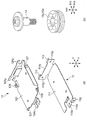
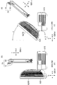
- FIG. 1A is a perspective view showing a base portion and an HDD attachment portion
- FIG. 2B is a perspective view showing a buffer member and attachment screws.
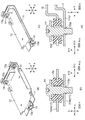
- FIG. 2 is a cross-sectional view of the HDD holding device shown in FIG. 1, wherein (a) is a perspective view showing the HDD holding device cut along a cutting line passing through one of the two first buffer members.
- FIG. 4B is a cross-sectional view of one first buffer member in FIG. 1A, and FIG.
- FIG. 2C is an HDD holding section cut along a cutting line passing through the other first buffer member.
- the perspective view which shows an apparatus (d) is sectional drawing around the other 1st buffer member in (c).
- FIG. 2 is a cross-sectional view of the HDD holding device shown in FIG. 1, wherein (a) is a perspective view showing the HDD holding device cut along a cutting line passing through two first buffer members; ) Is a cross-sectional view around the two first buffer members in (a).
- FIG. 2 is a diagram showing the HDD holding device shown in FIG.
- FIG. 1 is a perspective view showing the HDD holding device cut along a cutting line passing through a second buffer member, and (b) is (b) Sectional drawing around the 2nd buffer member in a), (c) is a perspective view which shows the HDD holding device cut
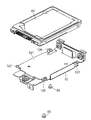
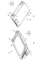
- FIG. 2 is a perspective view showing the HDD holding device shown in FIG. 1 and an HDD to be held. It is a figure which shows the HDD unit by embodiment of this invention, (a) is the perspective view seen from upper direction, (b) is the perspective view seen from the downward direction. 8 is a diagram showing the HDD unit shown in FIG.
- FIG. 7 shows (a) is a plan view seen from above, (b) is a front view, and (c) is a right side view.
- FIG. It is a figure which shows the POS terminal device which is information processing apparatus by embodiment of this invention, (a) is a perspective view, (b) is a right view. It is the figure which shows the inside of the display part in the POS terminal device shown by FIG. 9, (a) is the perspective view which removed and removed the top cover and the rear cover, (b) showed the inside of the display part partially. It is sectional drawing.
- FIG. 10 is a diagram for explaining the correspondence between the tilt state of the display unit in the POS terminal device shown in FIG. 9 and the tilt state of the HDD unit (HDD holding device) built in the display unit, and FIG.
- FIG. 4B is a right side view showing the POS terminal device including the state display unit
- FIG. 5B is a right side view showing the HDD unit (HDD holding device) built in the display unit in the upright state
- FIG. FIG. 4D is a right side view showing a POS terminal device including a tilted display unit tilted to the side
- FIG. 4D is a right side view showing an HDD unit (HDD holding device) built in the tilted display unit.
- the HDD holding device has a base portion, a plurality of buffer members, and an HDD mounting portion.
- the plurality of buffer members each have a mounting axis direction.
- the HDD attachment portion is attached with an HDD (hard disk drive) and is supported by the base portion via a plurality of buffer members.
- the plurality of buffer members also include a first buffer member and a second buffer member.
- the first buffer member includes a first direction, a second direction, and a third direction in which the mounting axis direction is any of the width direction, the depth direction, and the height direction of the base portion. It is interposed between the base portion and the HDD mounting portion so as to follow the direction. The second buffer member is interposed between the base portion and the HDD mounting portion so that the mounting shaft direction is along the second direction.
- the HDD holding device can exhibit a sufficient shock absorbing effect even if it is used at any angle or in a situation where the angle changes.
- the shock absorbing member has a shock absorbing action only in one of the three axial directions or has a shock absorbing action in a plurality of directions. Even if the direction having the shock absorber is determined, each of the shock absorbers has the shock absorbing member in which the direction having the highest shock absorbing action is directed in at least two directions. For this reason, when the HDD holding device according to the present invention is mounted as a component part of the HDD unit on a tiltable portion of the information processing apparatus, it is used at various angles according to the tilt of the tiltable portion, or Even when used in a situation where the angle changes, a sufficient shock absorbing effect can be exhibited.
- an HDD holding device 10 includes, for example, a base portion 11 formed by processing a galvanized steel sheet, For example, it has a plurality of elastically deformable buffer members 13z and 13y made of butyl rubber and an HDD mounting portion 12 formed by sheet metal processing of, for example, a galvanized steel plate.
- each of the plurality of buffer members 13z and 13y has a substantially cylindrical shape and has an attachment axis direction A13 that is also a cylinder axis direction.
- the HDD mounting portion 12 is supported by the base portion 11 via a plurality of buffer members 13z and 13y, as well as an HDD (hard disk drive) to be described later.
- the base portion 11 includes a main surface 111, a transparent hole portion 112 described later, two insertion guide portions 113, a pedestal portion 114y, and two screw hole portions 115y. And a pedestal part 114z and a screw hole part 115z.
- the insertion guide part 113 is for making it easy to insert the HDD unit into an HDD housing part (not shown) formed on the frame in the display part 620.
- the HDD mounting portion 12 includes a main surface 121, two cutout portions 124y, a cutout portion 124z, two transparent hole portions 126 described later, and two positions described later. Positioning protrusions 127.
- the plurality of buffer members also include a first buffer member (buffer member 13y) and a second buffer member (buffer member 13z).
- the mounting axis direction A13 (FIG. 2B) is any one of the width direction (X direction), the depth direction (Y direction), and the height direction (Z direction) of the base portion 11.
- the base unit 11 and the HDD are mounted so as to be along the first direction (Y direction) of the first direction (Y direction), the second direction (Z direction) and the third direction (X direction). It is interposed between the part 12.
- the second buffer member 13z is interposed between the base portion 11 and the HDD mounting portion 12 so that the mounting shaft direction is along the second direction (Z direction).
- the shock-absorbing members 13z and 13y are substantially cylindrical and have a mounting axial direction. Both A13 and a radial direction R13 (only two of the radial directions are shown in the figure) that are orthogonal to the mounting axis direction A13 have an impact absorbing function. However, the buffer members 13z and 13y have the highest impact absorbing action in the mounting axis direction A13.
- the buffer member 13z is inserted into the notch portion 124z formed in the HDD attachment portion 12 in a state where the shock absorbing action can be exerted. Further, the buffer member 13z inserted into the notch portion 124z of the HDD mounting portion 12 is in a state in which it can exert an impact absorbing action, and a flange hole is inserted into the screw hole portion 115z formed in the base portion 114z formed in the base member 11. Screwed with the attached screw 14.
- the two buffer members 13y are also inserted into the notches 124y formed in the HDD mounting portion 12 in a state where the shock absorbing action can be exhibited. Further, the buffer member 13y inserted into the notch portion 124y of the HDD mounting portion 12 is capable of exerting an impact absorbing action, and is connected to the screw hole portion 115y formed in the base portion 114y formed in the base member 11 with a flange. Screwed with the attached screw 14.
- the HDD holding device 10 does not absorb the vibration in the width direction (X direction) of the base portion 11.
- the shock in the depth direction (Y direction) of the base portion 11 is absorbed by the shock absorbing action in the mounting axis direction A13 of the two buffer members 13y and the shock absorbing action in the radial direction R13 of the buffer member 13z.
- the shock absorbing action in the depth direction (Y direction) of the base portion 11 is the highest. This is because the basic posture is that the Y direction is vertical when a later-described HDD 60 that is to be held by the HDD holding device 10 is mounted on a POS terminal device that will be described later. This is because the impact according to its own weight is considered to be the largest.
- the impact in the height direction (Z direction) of the base portion 11 is absorbed by the impact absorbing action in the mounting axis direction A13 of the buffer member 13z and the shock absorbing action in the radial direction R13 of the two buffer members 13y.
- the shock absorbing action in the height direction (Z direction) of the base portion 11 is next to the shock absorbing action in the depth direction (Y direction) of the base portion 11.
- the impact in the width direction (X direction) of the base portion 11 is absorbed by the shock absorbing action in the radial direction R13 of the buffer member 13z and the shock absorbing action in the radial direction R13 of the two buffer members 13y.
- the mounting shaft direction is any of the width direction (X direction), the depth direction (Y direction), and the height direction (Z direction) of the base portion 11.
- the base portion and the HDD mounting portion along the third direction (X direction) of the second direction (Z direction), the first direction (Y direction) and the third direction (X direction).
- a third buffer member interposed between the first and second buffers.
- at least one of the first buffer member, the second buffer member, and the third buffer member may be two or three or more.
- the HDD 60 is, for example, a 2.5-inch hard disk drive, and 4 on each of the left and right side surfaces and the bottom surface thereof. There are screw holes for fixing the parts. In the present embodiment, the screw hole on the bottom surface of the HDD 60 is used.
- the HDD mounting portion 12 of the HDD holding device 10 includes two transparent hole portions 126 and two positioning protrusions 127. Of the four screw holes on the bottom surface of the HDD 60, the positioning projections 127 are inserted into the two screw holes on the first diagonal, and the two screw holes on the second diagonal.
- the HDD 60 is fixed to the HDD mounting portion 12 of the HDD holding device 10 by screwing the screw 65 through the transparent hole portion 126.
- the HDD holding device 10 and the HDD 60 attached to the HDD mounting portion 12 of the HDD holding device 10 constitute an HDD unit 70.
- one buffer member 13z is provided on the connector side of the HDD 60 along the mounting axis direction in the Z direction, while the mounting axis direction is set in the Y direction on the side opposite to the connector side of the HDD 60.
- two buffer members 13y are provided along the two sides
- two buffer members are provided on the HDD connector side along the mounting axis direction in the Y direction
- Z is provided on the opposite side of the HDD connector side.
- One buffer member may be provided along the direction of the mounting axis. In that case, in order to lead out the cable connected to the connector of the HDD, a space is secured between the two buffer members along the mounting axis direction in the Y direction.
- the shape between the two cushioning members in the pedestal portion 114y (FIG. 2A) is cut out.
- the HDD unit 70 is a POS terminal as an information processing apparatus. It is mounted on the device 600.
- the POS terminal device 600 has a main body 610 as a base part and a display part 620 attached to the main body 610 via a tilt hinge unit 630.
- the display unit 620 includes a rear cover 626 and a top cover 627 that are detachably mounted.
- the display unit 620 has a tilt angle along the depth direction D of the main body 610 from the upright state in which the display surface 620S is along the height direction H of the main body 610. Tilt is possible in the range of ⁇ . The angle ⁇ is approximately 40 degrees in the present embodiment. Note that the display surface 620S can be tilted only backward in the depth direction D so that the display surface 620S looks upward, but the display surface 620S may be tiltable to the front side in the depth direction D so that the display surface 620S faces downward.
- the POS terminal device 600 includes a power supply unit (not shown), a control unit that controls the overall operation of the POS terminal device 600, and a display with a touch panel in which a liquid crystal display or the like and a touch panel are stacked.
- This control unit has an arithmetic element and also serves as an information processing unit that performs processing related to the settlement of products purchased by the customer.
- the power supply unit is built in the main body 610.
- the display with a touch panel is built in the display unit 620.
- reference numeral 620S denotes a display surface of a display with a touch panel.
- the control unit is detachably incorporated in the display unit 620 as a control circuit board 640.
- FIGS. 10A and 10B illustration of some mounted objects on the control circuit board 640 is omitted.
- the control circuit board 640 is electrically connected to the power supply unit and the display unit with a touch panel.
- the control circuit board 640 is further electrically connected to the HDD 60 of the HDD unit 70 as will be described later.
- the HDD unit 70 is based on the first direction (Y direction) of the HDD holding device 10 as shown in FIG. 11B.
- the display unit 620 is built in such a way that the height direction H of the main body 610 which is the base portion is along the second direction (Z direction) of the HDD holding device 10 is along the depth direction D of the main body 610. .
- the mounting axis direction A13 of the two buffer members 13y as the first buffer members (FIG. 3A). Etc.) along the height direction H of the main body 610, and the mounting axis direction A13 (FIG. 5A, etc.) of the buffer member 13z as the second buffer member is along the depth direction D of the main body 610. Further, it is built in the display unit 620.
- the HDD 60 of the HDD unit 70 built in the display unit 620 is electrically connected to the control circuit board 640 via the cable 650.
- the base portion 11 of the HDD holding device 10 includes two insertion guide portions 113 and one transparent hole portion 112. As shown in FIG.
- the HDD unit 70 is inserted from an opening of the display unit 620 from which the top cover 627 is removed into an HDD housing unit (not shown) formed on the frame in the display unit 620.
- a screw 660 (FIG. 10A) is threaded through the transparent hole 112 (FIG. 7A) into the screw hole formed in the frame not to be mounted, and the HDD unit 70 is fixed in the display unit 620.
- the connector of the HDD 60 of the HDD unit 70 and the control circuit board 640 are electrically connected via the cable 650.
- the top cover 627 is attached to the display unit 620.
- the HDD unit 70 is removed through the reverse procedure.
- the display unit 620 is tilted from the upright state shown in FIG. 11A to the tilt angle ⁇ (about 40 degrees) to the rear side in the depth direction D of the main body 610 as shown in FIG. 11C. Accordingly, the HDD unit 70 built in the display unit 620 is also tilted up to about 40 degrees. During this tilting, that is, when the tilt angle of the display unit 620 is changed, when the display unit 620 is tilted to the maximum and hits the rearward tilt end, and further, the tilted display unit 620 is returned to the upright state before Even when it hits the inclined end, the shock is sufficiently absorbed by the cooperation of the two buffer members 13y as the first buffer members and the buffer member 13z as the second buffer member. . As a result, the HDD 60 of the HDD unit 70 does not hinder the operation.
- the HDD is cited as a holding target
- the holding device according to the present invention is an information recording device such as an optical disk drive, a wired or wireless type communication device, or Units such as control devices and information input / output interface devices can be easily attached to and detached from higher-level equipment, and hold all electronic devices including electronic circuits and precision mechanical structures that are not subject to impact. Can be targeted. That is, the present invention proposes an electronic device holding device.
- the present invention can also be applied to an electronic device other than an information processing device such as a POS terminal device as a host device of the holding device.
Landscapes
- Engineering & Computer Science (AREA)
- General Engineering & Computer Science (AREA)
- Theoretical Computer Science (AREA)
- Physics & Mathematics (AREA)
- Mechanical Engineering (AREA)
- General Physics & Mathematics (AREA)
- Human Computer Interaction (AREA)
- Computer Hardware Design (AREA)
- Power Engineering (AREA)
- Chemical & Material Sciences (AREA)
- Combustion & Propulsion (AREA)
- Acoustics & Sound (AREA)
- Aviation & Aerospace Engineering (AREA)
- Devices For Indicating Variable Information By Combining Individual Elements (AREA)
- Vibration Prevention Devices (AREA)
- Fittings On The Vehicle Exterior For Carrying Loads, And Devices For Holding Or Mounting Articles (AREA)
- Casings For Electric Apparatus (AREA)
Abstract
本発明によるHDD保持装置10は、ベース部11と、複数の緩衝部材と、HDD60が取り付けられるHDD取付部12とを有している。複数の緩衝部材は、その取付軸方向が、前記ベース部の幅方向(X方向)、奥行方向(Y方向)および高さ方向(Z方向)のうちのY方向に沿うようにベース部11とHDD取付部12との間に介在する第1の緩衝部材である緩衝部材13yと、取付軸方向がZ方向に沿うようにベース部11とHDD取付部12との間に介在する第2の緩衝部材である緩衝部材13zとを含んでいる。
Description
本発明は、HDDを保持するHDD保持装置、HDD保持装置およびHDDを有するHDDユニットならびにHDDユニットを有する情報処理装置に関する。
POS(Point Of Sales)端末装置等の情報処理装置にHDD(Hard Disk Drive)を搭載する際に、着脱作業の容易化等を図るために、HDDを保持するHDD保持装置が用いられることがある。HDD保持装置と、これに保持されるHDDとの組み合わせにより、HDDユニットが構成される。そして、HDDユニットは、情報処理装置に対して取り外し可能に搭載される。
ところで、HDDは、振動や衝撃(以後、単に衝撃と表記する)を受けることにより、動作に支障を来たしたり、故障したりする虞がある。このため、HDDは、衝撃吸収作用を持たせたものが一般的である。
衝撃吸収効果をさらに高めるために、ドライブ自体の衝撃吸収作用に加え、HDD保持装置にも衝撃吸収作用を持たせたものが、提案もしくは実用化されている。
衝撃吸収作用を有するHDD保持装置は、例えば、特許文献1に開示されている。特許文献1に開示されたHDD保持装置は、HDDが取り付けられる補強材と、HDDが取り付けられた補強材を4つの緩衝部材を介して支持する支持部材とを有している。4つの緩衝部材の取付軸方向はいずれも、HDD保持装置の高さ方向に沿うように配置されている。
ところで、POS端末装置等の情報処理装置には、基台部と、基台部にチルト可能に取り付けられたディスプレイ部とを有するものがある。そのような情報処理装置におけるチルト可能なディスプレイ部にHDDユニットが搭載される場合、ディスプレイ部のチルトに伴ってHDDユニットもディスプレイ部内で様々な角度の姿勢となることなる。
一方、HDD保持装置における緩衝部材は、3軸方向のうちの一方向にのみ衝撃吸収作用を有するものや、複数方向に衝撃吸収作用を有するものがある。ただし、複数方向に衝撃吸収作用を有する緩衝部材は、複数方向に同等の衝撃吸収作用を有するわけではなく、最も高い衝撃吸収作用を有する方向が決まっている。例えば、特許文献1に開示されたHDD保持装置における4つの緩衝部材は、その取付軸方向にのみ衝撃吸収作用を有するか、あるいは、取付軸方向に最も高い衝撃吸収作用を有すると考えられる。
このことを考慮すると、情報処理装置のチルト可能なディスプレイ部に搭載されたHDDユニットは、ディスプレイ部のチルトに伴い、十分な衝撃吸収効果を発揮することができない傾きで使用される場合がある。
しかも、情報処理装置のユーザがディスプレイ部をチルトさせる際、即ち、ディスプレイ部のチルト角度が変化する時、また、ディスプレイ部が最大限チルトされて後傾端または前傾端に突き当たる時は、衝撃が発生し易い状況にあり、上記のようにHDDユニットが十分な衝撃吸収効果を発揮することができないことは好ましくない。
それ故、本発明の目的は、如何なる角度で、あるいは、角度が変化する状況で使用されても十分な衝撃吸収作用を発揮することができるHDD保持装置を提供することである。
本発明の他の目的は、上記のようなHDD保持装置と、HDDとを有するHDDユニットを提供することである。
本発明のさらに他の目的は、上記のようなHDDユニットを有する情報処理装置を提供することである。
本発明の一実施態様によれば、ベース部と、それぞれ取付軸方向を有する複数の緩衝部材と、HDDが取り付けられると共に前記複数の緩衝部材を介して前記ベース部によって支持されるHDD取付部とを有し、前記複数の緩衝部材は、前記取付軸方向が、前記ベース部の幅方向、奥行方向および高さ方向のそれぞれいずれかである第1の方向、第2の方向および第3の方向のうちの該第1の方向に沿うように前記ベース部と前記HDD取付部との間に介在する第1の緩衝部材と、前記取付軸方向が前記第2の方向に沿うように前記ベース部と前記HDD取付部との間に介在する第2の緩衝部材とを含むことを特徴するHDD保持装置が得られる。
本発明の他の実施態様によれば、前記HDD保持装置と、前記HDD保持装置によって保持された前記HDDとを有することを特徴とするHDDユニットが得られる。
本発明のさらに他の実施態様によれば、前記HDDユニットと、情報を処理する情報処理部とを有することを特徴とする情報処理装置が得られる。
本発明によれば、如何なる角度で、あるいは、角度が変化する状況で使用されても十分な衝撃吸収作用を発揮することができるHDD保持装置が得られる。
本発明によるHDD保持装置は、ベース部と、複数の緩衝部材と、HDD取付部とを有している。
複数の緩衝部材は、それぞれ取付軸方向を有している。HDD取付部は、HDD(ハードディスクドライブ)が取り付けられると共に、複数の緩衝部材を介してベース部によって支持される。
複数の緩衝部材はまた、第1の緩衝部材と、第2の緩衝部材とを含んでいる。
第1の緩衝部材は、取付軸方向が、ベース部の幅方向、奥行方向および高さ方向のそれぞれいずれかである第1の方向、第2の方向および第3の方向のうちの第1の方向に沿うように、ベース部とHDD取付部との間に介在している。第2の緩衝部材は、取付軸方向が第2の方向に沿うように、ベース部とHDD取付部との間に介在している。
上記構成により、本HDD保持装置は、如何なる角度で、あるいは、角度が変化する状況で使用されても十分な衝撃吸収作用を発揮することができる。
即ち、本発明によるHDD保持装置は、緩衝部材が、3軸方向のうちの一方向にのみ衝撃吸収作用を有するものや、複数方向に衝撃吸収作用を有しているが、最も高い衝撃吸収作用を有する方向が決まっていたとしても、それぞれ最も高い衝撃吸収作用を有する向きが少なくとも2方向に向いた緩衝部材を有している。このため、本発明によるHDD保持装置は、情報処理装置のチルト可能な部位にHDDユニットの構成部品として搭載された際に、チルト可能な部位のチルトに伴って様々な角度で使用されたり、あるいは、角度が変化する状況で使用されても、十分な衝撃吸収作用を発揮することができる。
以下、図面を参照して、本発明によるHDD保持装置のより具体的な実施形態を説明する。
[HDD保持装置]
図1(a)および(b)ならびに図2(a)および(b)を参照すると、本発明の実施形態によるHDD保持装置10は、例えば亜鉛メッキ鋼板を板金加工して成るベース部11と、例えばブチルゴムから成り、弾性変形可能な複数の緩衝部材13z、13yと、例えば亜鉛メッキ鋼板を板金加工して成るHDD取付部12とを有している。
図1(a)および(b)ならびに図2(a)および(b)を参照すると、本発明の実施形態によるHDD保持装置10は、例えば亜鉛メッキ鋼板を板金加工して成るベース部11と、例えばブチルゴムから成り、弾性変形可能な複数の緩衝部材13z、13yと、例えば亜鉛メッキ鋼板を板金加工して成るHDD取付部12とを有している。
複数の緩衝部材13z、13yはそれぞれ、図2(b)に示されるように、略筒状を呈し、筒軸方向でもある取付軸方向A13を有している。
HDD取付部12は、後述するHDD(ハードディスクドライブ)が取り付けられると共に、複数の緩衝部材13z、13yを介してベース部11によって支持される。
ベース部11は、図2(a)に示されるように、主面111と、後述する透き孔部112と、2箇所の挿入ガイド部113と、台座部114yと、2箇所のネジ孔部115yと、台座部114zと、ネジ孔部115zとを備えている。挿入ガイド部113は、HDDユニットを、ディスプレイ部620内のフレームに形成された図示しないHDD収容部に挿入し易くするためのものである。
HDD取付部12は、図2(a)に示されるように、主面121と、2箇所の切欠部124yと、切欠部124zと、後述する2箇所の透き孔部126と、後述する2箇所の位置決め突起127とを備えている。
複数の緩衝部材はまた、第1の緩衝部材(緩衝部材13y)と、第2の緩衝部材(緩衝部材13z)とを含んでいる。
第1の緩衝部材13yは、取付軸方向A13(図2(b))が、ベース部11の幅方向(X方向)、奥行方向(Y方向)および高さ方向(Z方向)のそれぞれいずれかである第1の方向(Y方向)、第2の方向(Z方向)および第3の方向(X方向)のうちの第1の方向(Y方向)に沿うように、ベース部11とHDD取付部12との間に介在している。
また、第2の緩衝部材13zは、取付軸方向が第2の方向(Z方向)に沿うように、ベース部11とHDD取付部12との間に介在している。
図3(a)~(d)、図4(a)および(b)ならびに図5(a)~(d)をも参照すると、緩衝部材13z、13yは、略筒状を呈し、取付軸方向A13、ならびに、取付軸方向A13に直交するラジアル方向R13(図中、ラジアル方向のうち、二軸方向のみ図示している)の両方に、衝撃吸収作用を有している。ただし、緩衝部材13z、13yは、取付軸方向A13に最も高い衝撃吸収作用を有している。
緩衝部材13zは、衝撃吸収作用を発揮し得る状態で、HDD取付部12に形成された切欠部124zに挿入される。さらに、HDD取付部12の切欠部124zに挿入された緩衝部材13zは、衝撃吸収作用を発揮し得る状態で、ベース部材11に形成された台座部114zに形成されたネジ孔部115zに、フランジ付きネジ14によってネジ止めされる。
2個の緩衝部材13yも、衝撃吸収作用を発揮し得る状態で、HDD取付部12に形成された切欠部124yに挿入される。さらに、HDD取付部12の切欠部124yに挿入された緩衝部材13yは、衝撃吸収作用を発揮し得る状態で、ベース部材11に形成された台座部114yに形成されたネジ孔部115yに、フランジ付きネジ14によってネジ止めされる。
本実施形態においては、後述するPOS端末装置に搭載する用途時にベース部11の奥行方向(Y方向)やベース部11の高さ方向(Z方向)に比べて衝撃を受けることが少ないと想定されるベース部11の幅方向(X方向)に取付軸方向を沿わせた緩衝部材は設けていない。
ただし、本実施形態によるHDD保持装置10は、ベース部11の幅方向(X方向)の振動を吸収しないというわけではない。
即ち、ベース部11の奥行方向(Y方向)の衝撃は、2個の緩衝部材13yの取付軸方向A13の衝撃吸収作用と、緩衝部材13zのラジアル方向R13の衝撃吸収作用とで吸収する。本実施形態においては、ベース部11の奥行方向(Y方向)の衝撃吸収作用が、もっとも高い。これは、後述するPOS端末装置にHDD保持装置10の保持対象である後述するHDD60が搭載された際に、Y方向が垂直となるのが基本姿勢であり、なおかつ、基本姿勢のときにHDD60の自重に応じた衝撃が一番大きいと考えられるからである。
また、ベース部11の高さ方向(Z方向)の衝撃は、緩衝部材13zの取付軸方向A13の衝撃吸収作用と、2個の緩衝部材13yのラジアル方向R13の衝撃吸収作用とで吸収する。本実施形態においては、ベース部11の高さ方向(Z方向)の衝撃吸収作用が、ベース部11の奥行方向(Y方向)の衝撃吸収作用に次いで高い。
さらに、ベース部11の幅方向(X方向)の衝撃は、緩衝部材13zのラジアル方向R13の衝撃吸収作用と、2個の緩衝部材13yのラジアル方向R13の衝撃吸収作用とで吸収する。
尚、本発明によるHDD保持装置において、複数の緩衝部材としては、取付軸方向がベース部11の幅方向(X方向)、奥行方向(Y方向)および高さ方向(Z方向)のそれぞれいずれかである第2の方向(Z方向)、第1の方向(Y方向)および第3の方向(X方向)のうちの第3の方向(X方向)に沿うように、ベース部とHDD取付部との間に介在する第3の緩衝部材をさらに含んでいてもよい。その場合、第1の緩衝部材、第2の緩衝部材および第3の緩衝部材の少なくとも1つは、2個または3個以上あってもよい。
[HDDユニット]
図6、図7(a)および(b)ならびに図8(a)~(c)をも参照すると、HDD60は、例えば2.5インチ型ハードディスクドライブであり、その左右側面および底面にそれぞれ、4箇所の固定用ネジ孔部を備えている。本実施形態においては、HDD60の底面のネジ孔部を用いる。
図6、図7(a)および(b)ならびに図8(a)~(c)をも参照すると、HDD60は、例えば2.5インチ型ハードディスクドライブであり、その左右側面および底面にそれぞれ、4箇所の固定用ネジ孔部を備えている。本実施形態においては、HDD60の底面のネジ孔部を用いる。
図2(a)に示されるように、HDD保持装置10のHDD取付部12は、2箇所の透き孔部126と、2箇所の位置決め突起127を備えている。そして、HDD60の底面の4箇所のネジ孔部のうち、第1の対角線上にある2箇所のネジ孔部に位置決め突起127が挿入されると共に、第2の対角線上にある2箇所のネジ孔部に透き孔部126を貫通してネジ65が螺入されることにより、HDD60は、HDD保持装置10のHDD取付部12に固定される。そして、HDD保持装置10と、HDD保持装置10のHDD取付部12に取り付けられたHDD60とにより、HDDユニット70が構成される。
尚、本実施形態においては、HDD60のコネクタ側にZ方向に取付軸方向を沿わせた1個の緩衝部材13zを設ける一方、HDD60のコネクタ側とは反対の側にY方向に取付軸方向を沿わせた2個の緩衝部材13yを設けているが、HDDのコネクタ側にY方向に取付軸方向を沿わせた2個の緩衝部材を設ける一方、HDDのコネクタ側とは反対の側にZ方向に取付軸方向を沿わせた1個の緩衝部材を設けてもよい。その場合、HDDのコネクタに接続されるケーブルを導出するために、Y方向に取付軸方向を沿わせた2個の緩衝部材の間にスペースを確保する。本実施形態で言えば、台座部114y(図2(a))等における2個の緩衝部材の間の部分を切り欠いた形状とする。
[POS端末装置]
図9(a)および(b)、図10(a)および(b)ならびに図11(a)~(d)をも参照すると、本実施形態によるHDDユニット70は、情報処理装置としてのPOS端末装置600に搭載される。
図9(a)および(b)、図10(a)および(b)ならびに図11(a)~(d)をも参照すると、本実施形態によるHDDユニット70は、情報処理装置としてのPOS端末装置600に搭載される。
POS端末装置600は、基台部としての本体610と、チルトヒンジユニット630を介して本体610に取り付けられたディスプレイ部620とを有している。ディスプレイ部620は、それぞれ取り外し可能に装着されたリアカバー626およびトップカバー627を備えている。
図11(a)および(c)に示されるように、ディスプレイ部620は、その表示面620Sが本体610の高さ方向Hに沿った直立状態から、本体610の奥行方向Dに沿ってチルト角αの範囲でチルト可能である。角度αは、本実施形態において、角度αは、約40度である。尚、表示面620Sが上方を仰ぐように奥行方向Dの後方にのみチルト可能であるが、表示面620Sが下方に俯くように奥行方向Dの前側にもチルト可能であってもよい。
POS端末装置600は、図示しない電源部と、POS端末装置600の動作全般を制御する制御部と、液晶ディスプレイ等とタッチパネルとが積層されて成るタッチパネル付きディスプレイとを有している。この制御部は、演算素子を有し、顧客が購入する商品の精算に関する処理を行う情報処理部をも兼ねている。
電源部は、本体610に内蔵されている。タッチパネル付きディスプレイは、ディスプレイ部620に内蔵されている。図中、符号620Sは、タッチパネル付きディスプレイの表示面を示している。制御部は、図10(a)および(b)に示されるように、制御回路基板640として、ディスプレイ部620に取り外し可能に内蔵されている。尚、図10(a)および(b)においては、制御回路基板640上の一部の搭載物の図示を省略している。制御回路基板640は、電源部と、タッチパネル付きディスプレイ部とに電気的に接続されている。制御回路基板640はさらに、後述するように、HDDユニット70のHDD60にも電気的に接続されている。
ディスプレイ部620が図11(a)のように直立状態にあるときに、HDDユニット70は、図11(b)に示されるように、HDD保持装置10の第1の方向(Y方向)が基台部である本体610の高さ方向Hに沿うように、かつ、HDD保持装置10の第2の方向(Z方向)が本体610の奥行方向Dに沿うように、ディスプレイ部620に内蔵される。
即ち、HDDユニット70は、ディスプレイ部620が図11(a)のように直立状態にあるときに、第1の緩衝部材である2個の緩衝部材13yの取付軸方向A13(図3(a)等)が本体610の高さ方向Hに沿うように、かつ、第2の緩衝部材である緩衝部材13zの取付軸方向A13(図5(a)等)が本体610の奥行方向Dに沿うように、ディスプレイ部620に内蔵される。
図10(a)および(b)に示されるように、ディスプレイ部620に内蔵されたHDDユニット70のHDD60は、ケーブル650を介して制御回路基板640と電気的に接続される。
図2(a)に示されるように、HDD保持装置10のベース部11は、2箇所の挿入ガイド部113と、1箇所の透き孔部112とを備えている。
HDDユニット70は、図10(a)に示されるようにトップカバー627が取り外されたディスプレイ部620の開口部から、ディスプレイ部620内のフレームに形成された図示しないHDD収容部に挿入され、図示しないフレームに形成されたネジ孔部に透き孔部112(図7(a))を貫通してネジ660(図10(a))が螺入され、HDDユニット70はディスプレイ部620内に固定される。その後、HDDユニット70のHDD60のコネクタと、制御回路基板640とが、ケーブル650を介して電気的に接続される。この後、ディスプレイ部620にトップカバー627が取り付けられる。尚、HDD60のメインテナンスや修理の際には、上記と逆の手順を経て、HDDユニット70が取り外される。
さて、ディスプレイ部620が図11(a)に示された直立状態から図11(c)に示されるように本体610の奥行方向Dの後ろ側にチルト角α(約40度)までチルトされるのに伴い、ディスプレイ部620に内蔵されたHDDユニット70も、最大約40度まで傾斜する。このチルトの際、即ち、ディスプレイ部620のチルト角度が変化する時、ディスプレイ部620が最大限チルトされて後傾端に突き当たる時、さらに、チルトされたディスプレイ部620が直立状態に戻されて前傾端に突き当たる時であっても、第1の緩衝部材である2個の緩衝部材13yと、第2の緩衝部材である緩衝部材13zとが協働することにより、衝撃は十分に吸収される。その結果、HDDユニット70のHDD60は、動作に支障を来たすことがない。
以上、実施形態を参照して本発明を説明したが、本発明の構成や詳細については、当業者が理解し得る様々な変更を加えることができる。
例えば、発明の名称をも含めて本明細書においては、保持対象としてHDDを挙げたが、本発明による保持装置は、光学ディスクドライブ等の情報記録装置、有線または無線タイプの通信装置、あるいは、制御装置や情報入出力インターフェース装置等、ユニット化することで上位機器に対する着脱作業の簡便化を図ることができると共に衝撃を受けることが好ましくない、電子回路や精密機械構造を含む電子装置全般を保持対象とすることができる。即ち、本発明は、電子装置保持装置を提案するものである。また、保持装置の上位機器としては、POS端末装置等の情報処理装置以外の電子機器にも、本発明は適用可能である。
また、この出願は、2015年4月24日に出願された日本出願特願第2015-089151号を基礎とする優先権を主張し、その開示の全てをここに取り込む。
10 HDD保持装置
11 ベース部
111 主面
112 透き孔部
113 挿入ガイド部
114y、114z 台座部
115y、115z ネジ孔部
12 HDD取付部
121 主面
124y、124z 切欠部
126 透き孔部
127 位置決め突起
13y、13z 緩衝部材
14 フランジ付きネジ
60 HDD(ハードディスクドライブ)
65 ネジ
70 HDDユニット
600 POS端末装置
610 本体(基台部)
620 ディスプレイ部
620S 表示面
626 リアカバー
627 トップカバー
630 チルトヒンジユニット
640 制御回路基板
650 ケーブル
660 ネジ
11 ベース部
111 主面
112 透き孔部
113 挿入ガイド部
114y、114z 台座部
115y、115z ネジ孔部
12 HDD取付部
121 主面
124y、124z 切欠部
126 透き孔部
127 位置決め突起
13y、13z 緩衝部材
14 フランジ付きネジ
60 HDD(ハードディスクドライブ)
65 ネジ
70 HDDユニット
600 POS端末装置
610 本体(基台部)
620 ディスプレイ部
620S 表示面
626 リアカバー
627 トップカバー
630 チルトヒンジユニット
640 制御回路基板
650 ケーブル
660 ネジ
Claims (10)
- ベース部と、
それぞれ取付軸方向を有する複数の緩衝部材と、
HDDが取り付けられると共に前記複数の緩衝部材を介して前記ベース部によって支持されるHDD取付部とを有し、
前記複数の緩衝部材は、
前記取付軸方向が、前記ベース部の幅方向、奥行方向および高さ方向のそれぞれいずれかである第1の方向、第2の方向および第3の方向のうちの該第1の方向に沿うように前記ベース部と前記HDD取付部との間に介在する第1の緩衝部材と、
前記取付軸方向が前記第2の方向に沿うように前記ベース部と前記HDD取付部との間に介在する第2の緩衝部材とを含むことを特徴するHDD保持装置。 - 前記緩衝部材は、前記取付軸方向に衝撃吸収作用を有することを特徴とする請求項1に記載のHDD保持装置。
- 前記緩衝部材は、前記取付軸方向に直交する方向にも衝撃吸収作用を有すると共に、前記取付軸方向に最も高い衝撃吸収作用を有することを特徴とする請求項2に記載のHDD保持装置。
- 前記緩衝部材は、衝撃吸収作用を発揮し得る状態で前記HDD取付部に形成された切欠部に挿入され、
前記HDD取付部の前記切欠部に挿入された前記緩衝部材は、衝撃吸収作用を発揮し得る状態で前記ベース部材にネジ止めされることを特徴とする請求項1乃至3のいずれか一項に記載のHDD保持装置。 - 前記複数の緩衝部材は、前記取付軸方向が前記第3の方向に沿うように前記ベース部と前記HDD取付部との間に介在する第3の緩衝部材をさらに含むことを特徴とする請求項1乃至4のいずれか一項に記載のHDD保持装置。
- 前記第1の緩衝部材および前記第2の緩衝部材の少なくとも一方は、複数あることを特徴とする請求項1乃至4のいずれか一項に記載のHDD保持装置。
- 前記第1の緩衝部材、前記第2の緩衝部材および前記第3の緩衝部材の少なくとも1つは、複数あることを特徴とする請求項5に記載のHDD保持装置。
- 請求項1乃至7のいずれか一項に記載のHDD保持装置と、前記HDD保持装置によって保持された前記HDDとを有することを特徴とするHDDユニット。
- 請求項8に記載のHDDユニットと、情報を処理する情報処理部とを有することを特徴とする情報処理装置。
- 基台部と、前記基台部に取り付けられたディスプレイ部とをさらに有し、
前記ディスプレイ部は、表示面が前記基台部の高さ方向に沿った直立状態から前記基台部の奥行方向に沿ってチルト可能であり、
前記HDDユニットは、前記ディスプレイ部が前記直立状態にあるときに、前記第1の緩衝部材の前記取付軸方向が前記基台部の前記高さ方向に沿うように、かつ、前記第2の緩衝部材の前記取付軸方向が該基台部の前記奥行方向に沿うように、該ディスプレイ部に内蔵されることを特徴とする請求項9に記載の情報処理装置。
Priority Applications (3)
| Application Number | Priority Date | Filing Date | Title |
|---|---|---|---|
| CN201680021552.8A CN107533854B (zh) | 2015-04-24 | 2016-02-03 | Hdd保持装置、hdd单元以及信息处理设备 |
| US15/565,988 US10157641B2 (en) | 2015-04-24 | 2016-02-03 | HDD holding device, HDD unit, and information processing apparatus |
| MYPI2017703979A MY187090A (en) | 2015-04-24 | 2016-02-03 | Hdd holding device, hdd unit, and information processing apparatus |
Applications Claiming Priority (2)
| Application Number | Priority Date | Filing Date | Title |
|---|---|---|---|
| JP2015089151 | 2015-04-24 | ||
| JP2015-089151 | 2015-04-24 |
Publications (1)
| Publication Number | Publication Date |
|---|---|
| WO2016170714A1 true WO2016170714A1 (ja) | 2016-10-27 |
Family
ID=57143804
Family Applications (1)
| Application Number | Title | Priority Date | Filing Date |
|---|---|---|---|
| PCT/JP2016/000552 Ceased WO2016170714A1 (ja) | 2015-04-24 | 2016-02-03 | Hdd保持装置、hddユニットおよび情報処理装置 |
Country Status (4)
| Country | Link |
|---|---|
| US (1) | US10157641B2 (ja) |
| CN (1) | CN107533854B (ja) |
| MY (1) | MY187090A (ja) |
| WO (1) | WO2016170714A1 (ja) |
Cited By (2)
| Publication number | Priority date | Publication date | Assignee | Title |
|---|---|---|---|---|
| CN107390824A (zh) * | 2017-08-16 | 2017-11-24 | 合肥宗平计算机科技有限公司 | 硬盘抗震支架 |
| JP7482800B2 (ja) | 2021-01-14 | 2024-05-14 | 三菱電機株式会社 | ハードディスクドライブ本体用取付部材 |
Families Citing this family (5)
| Publication number | Priority date | Publication date | Assignee | Title |
|---|---|---|---|---|
| US10888173B2 (en) * | 2016-10-28 | 2021-01-12 | Sleep Number Corporation | Air controller with vibration isolators |
| TWI675285B (zh) * | 2018-07-30 | 2019-10-21 | 緯創資通股份有限公司 | 安裝組件以及其顯示裝置 |
| JP1645526S (ja) * | 2019-04-19 | 2019-11-11 | ||
| CN111755034B (zh) * | 2020-05-11 | 2021-10-22 | 中科可控信息产业有限公司 | 一种硬盘免螺丝快速组装装置 |
| US11832728B2 (en) | 2021-08-24 | 2023-12-05 | Sleep Number Corporation | Controlling vibration transmission within inflation assemblies |
Citations (5)
| Publication number | Priority date | Publication date | Assignee | Title |
|---|---|---|---|---|
| JPS6290497U (ja) * | 1985-11-28 | 1987-06-10 | ||
| US6697250B2 (en) * | 2001-11-15 | 2004-02-24 | Wistron Corporation | Liquid crystal display computer with a removable device frame |
| TWM366695U (en) * | 2009-03-04 | 2009-10-11 | First Int Computer Inc | Industrial computer |
| EP2134148A1 (en) * | 2008-06-11 | 2009-12-16 | Advanced Digital Broadcast S.A. | Attachment assembly for mounting electronic devices |
| US20130015317A1 (en) * | 2011-07-15 | 2013-01-17 | Pegatron Corporation | Vibration Isolation Storage Module |
Family Cites Families (18)
| Publication number | Priority date | Publication date | Assignee | Title |
|---|---|---|---|---|
| JPS62124688U (ja) | 1986-01-28 | 1987-08-07 | ||
| US5067041A (en) * | 1989-10-27 | 1991-11-19 | International Business Machines Corporation | Apparatus for reducing electromagnetic radiation from a computer device |
| JP3090068B2 (ja) * | 1996-11-13 | 2000-09-18 | 富士通株式会社 | 端末装置および記憶装置固定機構 |
| JPH10208462A (ja) | 1997-01-20 | 1998-08-07 | Nec Gumma Ltd | 情報処理装置の実装構造 |
| US6498722B1 (en) | 1999-10-22 | 2002-12-24 | Sun Microsystems, Inc. | Disk drive isolation mount |
| JPWO2003017278A1 (ja) | 2001-08-20 | 2004-12-09 | 富士通株式会社 | ディスクドライブのシェルフへの搭載構造 |
| JP4302605B2 (ja) | 2004-09-27 | 2009-07-29 | 東芝テック株式会社 | 商品販売データ処理装置 |
| KR20070121699A (ko) | 2005-03-23 | 2007-12-27 | 지라텍스 테크놀로지 리미티드 | 디스크 드라이브 지지용 장치 및 디스크 드라이브 테스트장치 |
| US7130187B1 (en) | 2005-04-27 | 2006-10-31 | Et&T Technology Co., Ltd. | Device of hard disk shock-resistance |
| KR100669287B1 (ko) | 2005-07-26 | 2007-01-16 | 주식회사 현대오토넷 | 차량용 하드디스크 드라이브 방진 장치 및 그 조립방법 |
| US20070297129A1 (en) | 2006-06-21 | 2007-12-27 | Kuo-Hsien Liu | Disk device with a dual vibration-proof structure |
| CN101363499B (zh) * | 2008-09-17 | 2011-05-11 | 杨敏 | 悬挂式防震系统 |
| JP2010073262A (ja) | 2008-09-19 | 2010-04-02 | Hitachi Ltd | 記録再生装置及びそれに用いられる防振支持装置 |
| JP2012104198A (ja) | 2010-11-11 | 2012-05-31 | Giga-Byte Technology Co Ltd | 防振トレー |
| CN202150156U (zh) | 2011-07-19 | 2012-02-22 | 青岛海信智能商用设备有限公司 | 硬盘拔插方便的pos一体机 |
| CN202453786U (zh) * | 2012-01-18 | 2012-09-26 | 研华科技(中国)有限公司 | 硬盘双重减震装置 |
| CN202584303U (zh) | 2012-05-28 | 2012-12-05 | 青岛海信智能商用系统有限公司 | 具有减振功能的硬盘可拔插pos一体机 |
| CN103677163A (zh) * | 2012-09-25 | 2014-03-26 | 鸿富锦精密工业(深圳)有限公司 | 硬盘固定装置 |
-
2016
- 2016-02-03 US US15/565,988 patent/US10157641B2/en active Active
- 2016-02-03 MY MYPI2017703979A patent/MY187090A/en unknown
- 2016-02-03 WO PCT/JP2016/000552 patent/WO2016170714A1/ja not_active Ceased
- 2016-02-03 CN CN201680021552.8A patent/CN107533854B/zh active Active
Patent Citations (5)
| Publication number | Priority date | Publication date | Assignee | Title |
|---|---|---|---|---|
| JPS6290497U (ja) * | 1985-11-28 | 1987-06-10 | ||
| US6697250B2 (en) * | 2001-11-15 | 2004-02-24 | Wistron Corporation | Liquid crystal display computer with a removable device frame |
| EP2134148A1 (en) * | 2008-06-11 | 2009-12-16 | Advanced Digital Broadcast S.A. | Attachment assembly for mounting electronic devices |
| TWM366695U (en) * | 2009-03-04 | 2009-10-11 | First Int Computer Inc | Industrial computer |
| US20130015317A1 (en) * | 2011-07-15 | 2013-01-17 | Pegatron Corporation | Vibration Isolation Storage Module |
Cited By (2)
| Publication number | Priority date | Publication date | Assignee | Title |
|---|---|---|---|---|
| CN107390824A (zh) * | 2017-08-16 | 2017-11-24 | 合肥宗平计算机科技有限公司 | 硬盘抗震支架 |
| JP7482800B2 (ja) | 2021-01-14 | 2024-05-14 | 三菱電機株式会社 | ハードディスクドライブ本体用取付部材 |
Also Published As
| Publication number | Publication date |
|---|---|
| CN107533854B (zh) | 2019-10-08 |
| US10157641B2 (en) | 2018-12-18 |
| MY187090A (en) | 2021-08-31 |
| CN107533854A (zh) | 2018-01-02 |
| US20180114548A1 (en) | 2018-04-26 |
Similar Documents
| Publication | Publication Date | Title |
|---|---|---|
| CN107533854B (zh) | Hdd保持装置、hdd单元以及信息处理设备 | |
| US7267313B2 (en) | Retaining device for the floating mounting of a flat screen and electronic display device comprising a flat screen and a retaining device | |
| US20060232564A1 (en) | Electronic apparatus | |
| JP6324922B2 (ja) | 共振を抑制する手ブレ防止オートフォーカスモジュール | |
| US7684180B2 (en) | Computer system with vibration absorbing cage | |
| CN102640223A (zh) | 面板应力消除的可调节阻尼结构和无螺钉组装的方法和设备 | |
| JP2006024283A (ja) | ラックマウント型収納ユニットおよびラックマウント型ディスクアレイ装置 | |
| JP6112642B2 (ja) | Hdd保持装置、hddユニットおよび情報処理装置 | |
| US20070297129A1 (en) | Disk device with a dual vibration-proof structure | |
| JP6354060B2 (ja) | 電子機器 | |
| KR101901537B1 (ko) | 보조 기억 장치를 구비하는 전자 기기 | |
| JP2005117445A (ja) | インターホンのタッチパネル取付構造 | |
| JP2014216265A (ja) | 表示装置および電子機器 | |
| JP6428056B2 (ja) | ケース構造及び電子機器 | |
| JP2005038538A (ja) | 外部記憶装置用緩衝部材 | |
| KR20150113442A (ko) | 평판 표시 패널용 베이스 프레임 | |
| JP6286859B2 (ja) | 電気機器 | |
| JP2010097080A (ja) | フラットパネルディスプレイ装置 | |
| JP2009109886A (ja) | 表示装置 | |
| JP2010097079A (ja) | フラットパネルディスプレイ装置 | |
| CN212966925U (zh) | 一种基于dsp的lcd液晶显示模 | |
| KR101018669B1 (ko) | 탄성 결합 부재를 갖는 하드디스크 베이 및 이를 구비하는 컴퓨터 케이스 | |
| CN212080038U (zh) | 一种无人机减震模块 | |
| KR100658757B1 (ko) | 플라즈마 디스플레이 장치 | |
| CN212341787U (zh) | 一种防碰撞计算机外壳 |
Legal Events
| Date | Code | Title | Description |
|---|---|---|---|
| 121 | Ep: the epo has been informed by wipo that ep was designated in this application |
Ref document number: 16782744 Country of ref document: EP Kind code of ref document: A1 |
|
| WWE | Wipo information: entry into national phase |
Ref document number: 15565988 Country of ref document: US |
|
| NENP | Non-entry into the national phase |
Ref country code: DE |
|
| 122 | Ep: pct application non-entry in european phase |
Ref document number: 16782744 Country of ref document: EP Kind code of ref document: A1 |