WO2016166915A1 - ステアリングホイール - Google Patents
ステアリングホイール Download PDFInfo
- Publication number
- WO2016166915A1 WO2016166915A1 PCT/JP2015/082219 JP2015082219W WO2016166915A1 WO 2016166915 A1 WO2016166915 A1 WO 2016166915A1 JP 2015082219 W JP2015082219 W JP 2015082219W WO 2016166915 A1 WO2016166915 A1 WO 2016166915A1
- Authority
- WO
- WIPO (PCT)
- Prior art keywords
- steering wheel
- damper
- airbag module
- diameter
- circle
- Prior art date
- Legal status (The legal status is an assumption and is not a legal conclusion. Google has not performed a legal analysis and makes no representation as to the accuracy of the status listed.)
- Ceased
Links
Images




Classifications
-
- B—PERFORMING OPERATIONS; TRANSPORTING
- B60—VEHICLES IN GENERAL
- B60R—VEHICLES, VEHICLE FITTINGS, OR VEHICLE PARTS, NOT OTHERWISE PROVIDED FOR
- B60R21/00—Arrangements or fittings on vehicles for protecting or preventing injuries to occupants or pedestrians in case of accidents or other traffic risks
- B60R21/02—Occupant safety arrangements or fittings, e.g. crash pads
- B60R21/16—Inflatable occupant restraints or confinements designed to inflate upon impact or impending impact, e.g. air bags
- B60R21/20—Arrangements for storing inflatable members in their non-use or deflated condition; Arrangement or mounting of air bag modules or components
- B60R21/203—Arrangements for storing inflatable members in their non-use or deflated condition; Arrangement or mounting of air bag modules or components in steering wheels or steering columns
-
- B—PERFORMING OPERATIONS; TRANSPORTING
- B62—LAND VEHICLES FOR TRAVELLING OTHERWISE THAN ON RAILS
- B62D—MOTOR VEHICLES; TRAILERS
- B62D1/00—Steering controls, i.e. means for initiating a change of direction of the vehicle
- B62D1/02—Steering controls, i.e. means for initiating a change of direction of the vehicle vehicle-mounted
- B62D1/04—Hand wheels
Definitions
- the present invention relates to a steering wheel that suppresses vibration transmitted from the vehicle body side.
- the steering wheel described in Patent Document 1 has a pair of horn plates connected to a metal core and an airbag module, and a dynamic damper, which is a vibration damping mechanism, is disposed between the horn plates.
- the dynamic damper is connected to one horn plate via an elastic body, and is configured to support the other horn plate so as to be movable in the vertical direction.
- vibration having the same or close frequency as the resonance frequency unique to the dynamic damper is transmitted from the steering wheel to the dynamic damper, the dynamic damper resonates and absorbs vibration energy of the steering wheel, thereby suppressing the vibration of the steering wheel.
- the resonance frequency unique to the dynamic damper described above varies depending on the spring constant of the elastic body made of rubber.
- the hardness of the rubber is adjusted in order to realize a desired resonance frequency.
- EPDM ethylene propylene diene rubber
- the vibration during idling of the vehicle varies depending on the individual vehicle, but is usually in the range of 28 Hz to 39 Hz.
- the hardness of the EPDM rubber material needs to be extremely low. Therefore, it is difficult to adjust the hardness and cost is high.
- the present invention has been made in view of the above-described conventional situation, and an object of the present invention is to provide a steering wheel that can effectively suppress vibration transmitted from the vehicle body side and reduce the cost of components.
- the steering wheel of the present invention is a steering wheel including a steering wheel main body and an airbag module attached to the steering wheel main body, and a plurality of dampers for damping are arranged on the same circumference.
- the diameter of the circle is 80 mm or more and 110 mm or less. In the steering wheel according to one aspect of the present invention, the diameter of the circle is 100 mm or less.
- a plurality of shaft members are erected on the surface of the cored bar part of the steering wheel main body, and the shaft is formed on the horn plate that forms a horn switch mechanism with the cored bar part.
- a plurality of openings through which the member is inserted are formed, the damper is disposed between the shaft member and the opening, and the airbag module is fixed to the horn plate.
- a plurality of pins protrudes from the back surface of the airbag module so as to be able to advance and retract in the protruding direction, and the pins are inserted into insertion holes formed in the cored bar portion of the steering wheel body.
- the airbag module is attached by inserting the distal end side, the rear end side of the pin is inserted through a guide column, and the guide column is held by the retainer of the airbag module via the damper.
- the damper includes ethylene propylene diene rubber.
- the resonance frequency of the airbag module is set to the vibration transmitted from the vehicle body side. Vibration can be effectively suppressed according to the frequency. Further, the hardness adjustment of the rubber material of the damper becomes easy, and the cost can be reduced.
- FIG. 1 It is an exploded view of the steering wheel concerning an embodiment. It is a figure which shows the back surface of the horn plate which concerns on embodiment. It is a fragmentary sectional view of the damper concerning an embodiment. It is a figure which shows the back surface of the horn plate to which the airbag module and damper which concern on embodiment were attached. It is a disassembled perspective view of the steering wheel which concerns on another embodiment. It is a perspective view of a steering wheel concerning another embodiment. It is sectional drawing of the steering wheel at the time of the airbag module attachment which concerns on another embodiment. It is a partial expanded sectional view of the steering wheel after the airbag module attachment which concerns on another embodiment. It is a perspective view of the damper used in Example 1. FIG. It is a graph which shows the measurement result of an Example and a comparative example. It is a graph which shows the relationship between the arrangement
- FIG. 1 is an exploded view of a steering wheel according to the embodiment
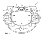
- FIG. 2 is a view showing a back surface (surface on the cored bar side) of the horn plate
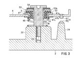
- FIG. 3 is a partial sectional view of a damper
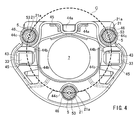
- FIG. It is a figure which shows the back surface of the horn plate to which the airbag module and the damper were attached.
- the steering wheel 1 has an airbag module 3 attached to a substantially central portion of the steering wheel body 10.
- the steering wheel body 10 includes a wheel part 11, a spoke part 12, a cored bar part 2, a horn plate 4, a damper 5, and a horn switch mechanism 6.
- the horn plate 4 is provided with a plurality of openings 41, and the openings 41 are inserted into the shaft member 21 erected on the surface of the cored bar 12.
- the damper 5 is disposed between the shaft member 21 and the opening 41.
- the horn switch mechanism 6 is formed between the cored bar 2 and the horn plate 4.
- the horn plate 4 is configured to be movable along the shaft member 21, and the airbag module 3 is fixed to the horn plate 4.
- the hub core part 2a of the cored bar part 2 is connected to the steering shaft.
- the airbag module 3 includes an airbag that is inflated and deployed in an emergency, an inflator 7 that supplies gas to the airbag, a retainer 31 that supports the airbag and the inflator 7, and a module that covers the airbag, the inflator 7 and the retainer 31. And a cover 32.
- the airbag, the inflator 7 and the module cover 32 can be arbitrarily applied with known configurations and are not limited to the illustrated shapes.
- the airbag module 3 is fixed to the horn plate 4 by a snap-in structure, for example.
- a claw portion 33 that is inserted into an opening 43 formed in the horn plate 4 is formed at the bottom of the retainer 31.
- the claw portion 33 has a shaft portion and a return portion. When the return portion is inserted into the opening 43 of the horn plate 4, the bending spring 45 disposed on the horn plate 4 is between the return portion and the bottom surface of the retainer 31. It is locked to.
- the horn plate 4 is constituted by an annular metal plate having an opening 42 in the center, for example, as shown in FIG.
- Two openings 43 are formed at the left and right positions of the flat portion of the horn plate 4.
- the centers of the three circular openings 41 are located on the same circumference.
- the claw 33 of the airbag module 3 is inserted into the opening 43, the inflator 7 of the airbag module 3 is inserted into the opening 42, and the damper 5 is disposed in the opening 41.
- a bending spring 45 is arranged so as to cross the opening 43.
- the bending spring 45 is composed of a metal rod formed in a substantially M shape, and is held by a projection 44a and a hook 44b so as to be slidable in the direction of the arrow in FIG.
- a snap-in structure is formed by the opening 43 and the bending spring 45.
- the horn plate 4 is urged in a direction away from the core metal part 2 by a coil spring 46 disposed between the horn plate 4 and the core metal part 2.
- the coil spring 46 is locked by a resin locking portion 47 provided at the peripheral edge of the opening 41.
- Flange portions 47a and 47b are respectively provided on the front surface (the surface on the airbag module 3 side) and the back surface (the surface on the core metal portion 2 side) of the locking portion 47, and the flange portions 47a and 47b are provided in the opening 41.
- the peripheral edge of is held.
- a hook portion 47 c that locks the coil spring 46 is formed on the back surface of the locking portion 47.
- the metal core part 2 is formed with a convex part 22 at a position where the shaft member 21 is fixed, and a bolt hole 23 is formed in the convex part 22.
- the convex portion 22 is formed to ensure the length of the bolt hole 23.
- the convex part 22 may be omitted.
- the shaft member 21 for example, a bolt having a head on a flange is used.
- the shaft member 21 is erected on the cored bar portion 2 by screwing the tip end portion 21 a of the shaft member 21 into the bolt hole 23.
- the shaft member 21 is disposed so as to pass through the opening 41 of the horn plate 4.
- the coil spring 46 is disposed between the convex portion 22 of the core metal part 2 and the horn plate 4.
- the horn switch mechanism 6 is constituted by the movable contact 61 arranged on the horn plate 4 and the fixed contact 62 arranged on the cored bar 2.
- the fixed contact 62 is fixed to, for example, the top of the convex portion 24 formed on the cored bar portion 2, and is disposed at a height that can contact the movable contact 61 by the vertical movement of the horn plate 4.
- the arrangement of the movable contact 61 and the fixed contact 62 is not limited to the illustrated configuration.
- the fixed contact 62 is fixed to the surface of the cored bar 2 and the movable contact 61 is extended downward from the rear surface of the horn plate 4. You may arrange.
- the damper 5 is provided on the surface side of the substantially cylindrical body 51 and the horn plate 4 disposed between the shaft member 21 and the opening 41, and overlaps the surface of the flange portion 47 a of the locking portion 47. Part 52.
- drum 51 and the collar part 52 are integrally formed.
- the flange portion 52 is formed in a flange shape whose entire circumference is enlarged with respect to the body portion 51.
- the damper 5 is preferably made of rubber having a hardness of 20 to 40, particularly about 25 to 35, according to JIS K 6253 compliant type A durometer.
- the rubber for example, a synthetic rubber such as ethylene propylene diene rubber or chloroprene rubber is suitable.
- a resin bush 53 is inserted into the body 51 of the damper 5.
- the bush 53 includes a shaft portion 53 a that is inserted into the body portion 51 of the damper 5, and a flange portion 53 b that is disposed on the upper surface of the flange portion 52 of the damper 5.
- the bush 53 prevents contact between the damper 5 and the shaft member 21 and suppresses wear of the damper 5.
- a thin annular elastic body 54 is inserted between the flange 53b of the bush 53 and the head of the shaft member 21. By disposing the elastic body 54, it is possible to suppress the generation of abnormal noise caused by the shaft member 21 and the bush 53 coming into contact when the horn plate 4 is moved up and down.
- the horn plate 4 moves along the shaft member 21 in the direction of the cored bar 2 (downward), and the movable contact 61 and the fixed contact 62 come into contact with each other. Blow.
- the damper 5, the bush 53, and the elastic body 54 disposed in the opening 41 also move along the shaft member 21 together with the horn plate 4.
- the horn plate 4 is returned to the original position by the action of the coil spring 46.
- the damper 5 functions as a dynamic damper that adjusts the vibration frequency of the airbag module 3, which is a mass body fixed to the horn plate 4, and cancels the vibration transmitted from the vehicle body side by the resonance of the airbag module 3. To do.
- the dampers 5 are arranged at the same place as the opening 41, that is, at three places, and the three dampers 5 are arranged on the same circumference of the circle C.
- the arrangement position of the damper 5 refers to the center position of the substantially cylindrical body 51 of the damper 5 and corresponds to the center position of the shaft member 21.
- the center of the circle C is located in the vicinity of the center of the annular wheel portion 11, in the vicinity of the center of gravity of the airbag module 3, or in an area between them. Is preferred.
- the center of the circle C is located in the vicinity thereof.
- the arrangement interval (distance in the circumferential direction) of the dampers 5 on the circumference of the circle C may be the same or different.
- the diameter of the circle C is preferably 80 mm or more and 110 mm or less, and particularly preferably 100 mm or less.
- the diameter (width) of the airbag module 3 of the steering wheel 1 is about 160 mm
- the damper 5 is disposed on the inner side (center side) from the middle point from the center of the airbag module 3 to the end of the airbag module 3. If it is done, the air bag module 3 is likely to rattle during the horn operation, which may impair comfort. Therefore, it is preferable that the damper 5 is disposed on the outer side (end side) from the middle point from the center of the airbag module 3 to the end of the airbag module 3, and the diameter of the circle C is the diameter of the airbag module 3 ( Preferably, it is at least half of the width), ie 80 mm or more.
- the inflator 7 inserted into the central opening 42 of the horn plate 4 is often manufactured to have a diameter of about 60 mm.
- the damper 5 preferably has a diameter of the flange portion 52 of 20 mm or more in consideration of the function as a dynamic damper.
- the diameter of the circle C is preferably 80 mm or more.
- the damper 5 functions as a dynamic damper that cancels the vibration transmitted from the vehicle body side by the resonance of the airbag module 3 and suppresses the vibration.
- the frequency of vibration transmitted from the vehicle body has a large component of 37 to 38 Hz, and the resonance frequency of the steering wheel 1 is preferably in this band.
- the resonance frequency changes according to the diameter of the circle C in which the damper 5 is arranged on the circumference thereof, and the resonance frequency decreases as the diameter of the circle C decreases.
- the weight of the airbag module 3 is 800 to 1100 g
- the damper 5 is made of rubber such as EPDM having a hardness of 25 to 35 according to a JIS K 6253 compliant type A durometer
- the diameter (outer diameter) of the collar portion 52 is 20 mm or more.
- the resonance frequency can be set to about 38 Hz by setting the diameter of the circle C to 110 mm, and the resonance frequency can be set to 100 mm by setting the diameter of the circle C to 100 mm. It can be about 37 Hz.
- the damper 5 is arranged on the circumference of the circle C, and the resonance frequency of the airbag module 3 is determined not by the hardness of the rubber material of the damper 5 but by the diameter of the circle C. Set to the frequency of vibration transmitted from the side. Therefore, vibration transmitted from the vehicle body side can be effectively suppressed, the hardness of the rubber material of the damper 5 can be easily adjusted, and the cost can be reduced.
- the center position of the circle C may be a position slightly deviated from the center of the wheel portion 11 or the center of gravity of the airbag module 3.
- the upper two dampers 5 in FIG. 4 are located on the circumference of the first circle centered on the center of the wheel part 11, and the lower one damper 5 is centered on the wheel part 11. It is located on the circumference of the second circle as the center position, and the diameter of the first circle and the diameter of the second circle may be different. Also in this case, the diameter of the first circle and the diameter of the second circle are both preferably 80 mm or more and 110 mm or less, and more preferably 100 mm or less.
- the number of the openings 41 for the damper 5 and the openings 43 into which the claw parts 33 are inserted is not limited to the illustrated one.
- FIG. 5 to 8 are views showing a steering wheel 120 according to another embodiment.
- FIG. 5 is an exploded perspective view of the steering wheel 120.
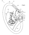
- FIG. 6 is a perspective view of the steering wheel 120.
- FIG. 7 is a cross-sectional view of the steering wheel 120 when the airbag module is attached.
- FIG. 8 is an enlarged sectional view of a part of the steering wheel 120 after the airbag module is attached.
- the steering wheel 120 is a steering wheel body 121 with an airbag module 140 attached thereto.
- the steering wheel main body 121 has a wheel part 122, a spoke part 123, and a cored bar part 124.
- the cored bar portion 124 includes a disk-shaped airbag device mounting portion 125 (hereinafter simply referred to as “mounting portion 125”), a pin insertion hole 126 provided in the mounting portion 125, a lock spring 127, a cored bar.
- a steering shaft mounting hole 128 provided at the center of the portion 124 is provided.
- the lock spring 127 is substantially U-shaped, and is arranged so that one side crosses the insertion hole 126 in the chord direction.
- the attachment portion 125 is provided with a tunnel-shaped spring holder 130 and stoppers 131 and 132 for positioning the lock spring 127.
- the lock spring 127 is inserted into the spring holder 130 and positioned by contacting the stoppers 131 and 132, and as described above, the lock spring 127 is attached to the attachment portion 125 so that one side crosses the insertion hole 126 in the chord direction.
- the airbag module 140 includes a retainer 141, an inflator 142 and an airbag 143 attached to the retainer 141, a module cover 144 that covers the airbag 143, and a plurality of protrusions projecting from the retainer 141 toward the attachment portion 125 ( In this embodiment, there are three pins 145, a horn plate 148, and the like. This pin 145 is inserted into the insertion hole 126.
- the airbag 143 is folded and attached to the retainer 141 with a bolt 146 together with the inflator 142.
- the inflator 142 ejects gas at the time of a vehicle collision
- the airbag 143 is inflated, and the module cover 144 is opened and deployed.
- the pin 145 is mounted in the pin holding hole 147 of the retainer 141.
- the pin 145 includes a pin front 150 and a pin rear 151.
- the pin rear 151 has a cylindrical portion 151a and a flange portion 151b.
- a female screw is provided on the inner peripheral surface of the cylindrical portion 151a.
- a horn switch contact tip 152 is screwed onto the female screw.
- a projection 148 t is provided on the horn plate 148 so as to face the contact chip 152.
- the horn plate 148 is fixed to the retainer 141 with bolts 146. When the airbag module 140 is pushed and retracted, the horn plate 148 and the contact tip 152 come into contact with each other, and the horn sounds.
- the front end portion of the pin front 150 is a tapered portion 150a, and a groove 150b is provided around the outer peripheral surface adjacent to the tapered portion 150a.
- the rear end side of the groove 150b is a straight shape portion 150c, and a flange portion 150d is provided on the rear end side of the straight shape portion 150c.
- the pin 145 has a male screw shaft portion 150e protruding rearward from the axial center portion of the flange portion 150d.
- the male screw shaft portion 150e is screwed onto the female screw of the cylindrical portion 151a of the pin rear 151, whereby the pin front 150 and the pin rear 151 are connected to form the pin 145.
- the pin rear 151 is slidably inserted into the guide column 153.
- a flange portion 153a is provided at the rear end of the guide column 153, and a claw portion 153b is provided at the front end portion.
- a vibration damper 154 is fitted on the guide column 153.
- the material of the damper 154 can be the same material as the damper 5 described above.
- One end surface of the damper 154 is in contact with the flange portion 153a.
- a washer 155 is disposed so as to overlap the other end surface of the damper 154. The washer 155 is locked to the claw portion 153b.
- Flange portions 154 a and 154 b are provided on both end sides of the damper 154, and the flange portions 154 a and 154 b sandwich the peripheral edge portion of the pin holding hole 147. Is held in.
- a rubber spacer 157 is provided so as to overlap the flange portion 153 a of the guide column 153.
- a coil spring 158 is interposed between the washer 155 and the flange portion 150d in a power storage state so as to surround the pin rear 151.
- the pins 145 are respectively opposed to the insertion holes 126, the airbag module 140 is moved toward the attachment portion 125, and the pins 145 are inserted into the insertion holes 126.
- the horn plate 148 contacts the contact tip 152 of the pin 145, and the pin 145 is pushed directly by the horn switch plate 148 and moves forward.
- the diameter (outer diameter) of the flange portion 154b of each damper 154 is set to 20 mm or more, and the axial length of the damper 154 is set to 5 mm or more.
- the diameter of the circle is 80 mm or more, 110 mm or less, particularly 100 mm or less.
- Each damper 154 is arranged on the same circumference. As a result, as described above, the resonance frequency of the airbag module 140 is effectively suppressed to match the vibration frequency transmitted from the vehicle body side, and the hardness of the rubber material of the damper 154 can be easily adjusted. And cost can be reduced.
- Example 1 The inertance of the airbag module was measured using the steering wheel 1 shown in FIGS. Three dampers 5 were arranged at intervals of 120 ° on the circumference of a circle with a diameter of 100 mm centered on the center of gravity of the airbag module 3.
- the weight of the airbag module 3 was 1070 g.
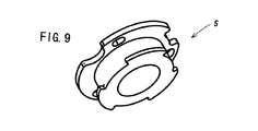
- an EPDM rubber material having a hardness of 33 according to a JIS K 6253 type A durometer was used, and a material having a shape as shown in FIG. 9 was used.
- the diameter (outer diameter) of the flange 52 of the damper 5 is 28 mm
- the thickness of the flange 52 is 1.5 mm
- the axial length of the damper 5 is 7.4 mm
- the inner diameter of the body 51 is 11.8 mm
- the outer diameter of the part 51 was 19.2 mm.
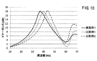
- the measurement results are shown in FIG.
- Example 1 inertance was measured in the same manner as in Example 1 except that three dampers 5 were arranged on the circumference of a circle having a diameter of 120 mm. The measurement results are shown in FIG.
- Example 2 In Example 1, inertance was measured in the same manner as in Example 1 except that the three dampers 5 were arranged on the circumference of a circle having a diameter of 140 mm. The measurement results are shown in FIG.
- the resonance frequency at which the inertance reaches a peak was 37 Hz in Example 1, 39 Hz in Comparative Example 1, and 43.25 Hz in Comparative Example 2.
- the graph shown in FIG. 11 shows an approximate curve obtained from the results of Example 1 and Comparative Examples 1 and 2, where the vertical axis represents the arrangement diameter of the damper 5 and the horizontal axis represents the resonance frequency. From this graph, it was confirmed that the resonance frequency decreased as the arrangement diameter of the damper 5 was reduced.
Landscapes
- Engineering & Computer Science (AREA)
- Mechanical Engineering (AREA)
- Chemical & Material Sciences (AREA)
- Combustion & Propulsion (AREA)
- Transportation (AREA)
- Steering Controls (AREA)
- Air Bags (AREA)
Abstract
車体側から伝達される振動を効果的に抑制すると共に、部品コストを削減できるステアリングホイールを提供する。ステアリングホイール1は、ステアリングホイール本体10と、このステアリングホイール本体10に取り付けられたエアバッグモジュール3とを備える。このステアリングホイール1には、複数のダンパ5が、直径80mm以上、110mm以下の円Cの同一円周上に配置され、エアバッグモジュール3の共振周波数が、車体側から伝達される振動の周波数に合わせられている。
Description
本発明は、車体側から伝達される振動を抑制するステアリングホイールに関する。
エンジンの回転による振動や走行時の路面からの振動がステアリングシャフトの乗員側先端に止着されるステアリングホイールに伝わると、その振動がステアリングホイールを握った運転者に伝わり、運転者に不快感を与えることがあった。そのため、ステアリングホイールの振動を抑制(制振)する技術が従来から提案されている。
特許文献1に記載されたステアリングホイールは、芯金及びエアバッグモジュールに接続された一対のホーンプレートを有し、このホーンプレート間に制振機構であるダイナミックダンパが配置されている。ダイナミックダンパは、一方のホーンプレートに弾性体を介して接続されるとともに、他方のホーンプレートを上下方向に移動可能に支持するように構成されている。ステアリングホイールからダイナミックダンパに対し、ダイナミックダンパ固有の共振周波数と同一又は近い周波数の振動が伝わると、ダイナミックダンパが共振してステアリングホイールの振動エネルギーが吸収され、ステアリングホイールの振動が抑制される。
上述のダイナミックダンパ固有の共振周波数は、ゴム製の弾性体のばね定数により変化し、例えば、所望の共振周波数を実現するために、ゴムの硬度が調整される。ゴム材には例えばエチレンプロピレンジエンゴム(EPDM)が用いられる。車両のアイドリング時の振動は、個々の車両によりそれぞれ異なるが、通常28Hz~39Hzの範囲にあり、ダイナミックダンパの共振周波数をこの範囲に収めるには、EPDMゴム材の硬度を極めて低くする必要があるため、硬度調整が困難であり、コストがかかっていた。
本発明は、上記従来の実状に鑑みてなされたものであり、車体側から伝達される振動を効果的に抑制すると共に、部品コストを削減できるステアリングホイールを提供することを課題とする。
本発明のステアリングホイールは、ステアリングホイール本体と、該ステアリングホイール本体に取り付けられたエアバッグモジュールとを備えたステアリングホイールであって、制振用の複数のダンパが同一円周上に配置され、この円の直径が80mm以上、110mm以下であることを特徴とする。本発明の一態様によるステアリングホイールにおいて、この円の直径は100mm以下であることを特徴とする。
本発明の一態様によるステアリングホイールにおいて、前記ステアリングホイール本体の芯金部の表面に複数の軸部材が立設され、前記芯金部との間でホーンスイッチ機構を形成するホーンプレートに、前記軸部材が挿通される複数の開口部が形成されており、前記ダンパは、前記軸部材と前記開口部との間に配置され、前記エアバッグモジュールは前記ホーンプレートに固定されている。
本発明の一態様によるステアリングホイールにおいて、前記エアバッグモジュールの背面から複数のピンが突出方向に進退可能に突設され、前記ステアリングホイール本体の芯金部に形成された差込穴に前記ピンの先端側が差し込まれて前記エアバッグモジュールが取り付けられ、前記ピンの後端側はガイドカラムに挿通されており、前記ガイドカラムが、前記ダンパを介して前記エアバッグモジュールのリテーナに保持されている。
本発明の一態様によるステアリングホイールにおいて、前記ダンパはエチレンプロピレンジエンゴムを含む。
本発明によれば、制振用の複数のダンパが、直径80mm以上、110mm以下の円の円周上に配置されているため、エアバッグモジュールの共振周波数を、車体側から伝達される振動の周波数に合わせ、振動を効果的に抑制できる。また、ダンパのゴム材の硬度調整が容易になり、コストを削減できる。
以下、図面を参照して本発明の実施の形態について説明する。図1は実施の形態に係るステアリングホイールの分解図であり、図2はホーンプレートの裏面(芯金側の面)を示す図であり、図3はダンパの部分断面図であり、図4はエアバッグモジュール及びダンパが取り付けられたホーンプレートの裏面を示す図である。
ステアリングホイール1は、ステアリングホイール本体10の略中央部にエアバッグモジュール3を取り付けたものである。ステアリングホイール本体10は、ホイール部11、スポーク部12、芯金部2、ホーンプレート4、ダンパ5、及びホーンスイッチ機構6を備える。
ホーンプレート4には複数の開口部41が設けられており、開口部41は、芯金部12の表面に立設された軸部材21に挿通される。ダンパ5は、軸部材21と開口部41との間に配置される。ホーンスイッチ機構6は、芯金部2とホーンプレート4との間に形成される。ホーンプレート4は、軸部材21に沿って移動可能に構成され、エアバッグモジュール3はホーンプレート4に固定されている。芯金部2のハブコア部2aがステアリングシャフトに接続される。
エアバッグモジュール3は、緊急時に膨張展開されるエアバッグと、エアバッグにガスを供給するインフレータ7と、エアバッグ及びインフレータ7を支持するリテーナ31と、エアバッグ、インフレータ7及びリテーナ31を覆うモジュールカバー32と、を有する。エアバッグ、インフレータ7及びモジュールカバー32については、公知の構成を任意に適用することができ、図示した形状に限定されない。
エアバッグモジュール3は、例えば、スナップイン構造によりホーンプレート4に固定される。リテーナ31の底部には、ホーンプレート4に形成された開口部43に挿入される爪部33が形成されている。爪部33は、軸部と返し部とを有し、返し部をホーンプレート4の開口部43に挿入すると、ホーンプレート4に配置された屈曲バネ45が返し部とリテーナ31の底面との間に係止される。
ホーンプレート4は、例えば、図2に示すように、中央に開口部42を有する環状の金属板により構成されている。ホーンプレート4の平面部の左右の位置に2つの開口部43が形成されている。3つの円形の開口部41の中心は同一円周上に位置している。開口部43にはエアバッグモジュール3の爪部33が挿入され、開口部42にはエアバッグモジュール3のインフレータ7が挿入され、開口部41にはダンパ5が配置される。
開口部43を横切るように屈曲バネ45が配置されている。屈曲バネ45は、略M字形状に形成された金属棒により構成されており、突起部44a及びフック部44bにより、図2の矢印方向にスライド可能に保持されている。
開口部43及び屈曲バネ45によりスナップイン構造が形成される。エアバッグモジュール3の爪部33が開口部43に挿入されると、屈曲バネ45が矢印方向に押し退かれてスライドし、爪部33の返し部を超えると屈曲バネ45が復元し、爪部33がホーンプレート4に固定される。
ホーンプレート4は、図3に示すように、芯金部2との間に配置されたコイルスプリング46によって芯金部2から離隔する方向に付勢されている。このコイルスプリング46は、開口部41の周縁部に設けられた樹脂製の係止部47により係止されている。係止部47の表面(エアバッグモジュール3側の面)と裏面(芯金部2側の面)には、それぞれフランジ部47a、47bが設けられており、フランジ部47a、47bが開口部41の周縁部を挟持している。係止部47の裏面に、コイルスプリング46を係止するフック部47cが形成されている。
芯金部2には、軸部材21を固定する箇所に凸部22が形成されており、凸部22にボルト穴23が形成されている。凸部22は、ボルト穴23の長さを確保するために形成される。芯金部2が十分な厚みを持つ場合には、凸部22を省略してもよい。
軸部材21には、例えば、フランジ上の頭部を有するボルトが使用される。軸部材21の先端部21aがボルト穴23に螺合されることによって、軸部材21が芯金部2に立設される。軸部材21は、ホーンプレート4の開口部41を挿通するように配置されている。コイルスプリング46は、芯金部2の凸部22とホーンプレート4との間に配置される。
ホーンプレート4に配置された可動接点61と、芯金部2に配置された固定接点62とにより、ホーンスイッチ機構6が構成される。固定接点62は、例えば、芯金部2に形成された凸部24の頂部に固定されており、ホーンプレート4の上下移動によって、可動接点61と接触可能な高さに配置されている。可動接点61及び固定接点62の配置は図示した構成に限定されず、例えば、固定接点62を芯金部2の表面に固定し、可動接点61をホーンプレート4の裏面から下方に延伸した位置に配置してもよい。
ダンパ5は、軸部材21と開口部41との間に配置される略円筒形状の胴部51と、ホーンプレート4の表面側に設けられ、係止部47のフランジ部47aの表面に重なる鍔部52とを有する。胴部51と鍔部52とは一体に形成されている。鍔部52は、胴部51に対して全周が拡径したフランジ状に形成されている。ダンパ5は、JIS K 6253準拠のタイプAデュロメータによる硬度が好ましくは20~40特に25~35程度のゴムよりなる。ゴムとしては、例えばエチレンプロピレンジエンゴム、クロロプレンゴム等の合成ゴムが好適である。
ダンパ5の胴部51には、樹脂製のブッシュ53が挿入される。ブッシュ53は、ダンパ5の胴部51に挿入される軸部53aと、ダンパ5の鍔部52の上面に配置されるフランジ部53bとを有する。ブッシュ53は、ダンパ5と軸部材21との接触を防止して、ダンパ5の摩耗を抑制する。
ブッシュ53のフランジ部53bと、軸部材21の頭部との間には、薄板円環形状の弾性体54が挿入される。弾性体54を配置することで、ホーンプレート4を上下移動させた際に、軸部材21とブッシュ53とが接触して生じる異音の発生を抑制することができる。
ホーンプレート4とダンパ5との間には係止部44が設けられ、軸部材21とダンパ5との間にはブッシュ53が設けられるため、ダンパ5と金属部品との接触を回避することができ、ダンパ5の摩耗や劣化を抑制できる。
エアバッグモジュール3を押下することにより、ホーンプレート4が軸部材21に沿って芯金部2の方向(下方向)に移動し、可動接点61と固定接点62とが接触することにより、ホーンが吹鳴する。このとき、開口部41に配置されたダンパ5、ブッシュ53及び弾性体54もホーンプレート4と共に軸部材21に沿って移動する。そして、エアバッグモジュール3の押下する力が解除されると、コイルスプリング46の作用によって、ホーンプレート4は、元の位置に復帰する。
ダンパ5は、ホーンプレート4に固定された質量体であるエアバッグモジュール3の振動周波数を調整し、車体側から伝達される振動をエアバッグモジュール3の共振により打ち消して制振するダイナミックダンパとして機能する。
図4に示すように、ダンパ5は開口部41と同じ箇所、すなわち3ヶ所に配置され、3個のダンパ5は、円Cの同一円周上に配置されている。ここで、ダンパ5の配置位置とは、ダンパ5の略円筒形状の胴部51の中心位置をいい、軸部材21の中心位置に相当する。ステアリングホイール1に正対してステアリングホイール1を見た状態において、円Cの中心は、円環形のホイール部11の中心付近、エアバッグモジュール3の重心付近、又はそれらの間の領域に位置することが好ましい。ホイール部11の中心とエアバッグモジュール3の重心とが一致する場合には、これらの近傍に円Cの中心が位置することが好ましい。円Cの円周上におけるダンパ5の配置間隔(周方向の距離)は同じでもよいし、異なっていてもよい。
本実施形態において、円Cの直径は、80mm以上、110mm以下とすることが好ましく、特に100mm以下とすることが好ましい。
一般に、ステアリングホイール1のエアバッグモジュール3の直径(幅)は160mm程度であり、エアバッグモジュール3の中心からエアバッグモジュール3の端部までの中間点より内側(中心側)にダンパ5が配置されると、ホーン操作の際にエアバッグモジュール3がガタつきやすくなり、快適性を損なわせることがある。そのため、ダンパ5は、エアバッグモジュール3の中心からエアバッグモジュール3端部までの中間点より外側(端部側)に配置されることが好ましく、円Cの直径はエアバッグモジュール3の直径(幅)の半分以上、すなわち80mm以上であることが好ましい。
ホーンプレート4の中央の開口部42に挿入されるインフレータ7は、直径が60mm程度となるように製造されることが多い。ダンパ5は、ダイナミックダンパとしての機能を考慮して、鍔部52の直径を20mm以上とすることが好ましい。ダンパ5をインフレータ7に干渉しないように配置するために、円Cの直径は80mm以上とすることが好ましい。
上述したように、ダンパ5は、車体側から伝達される振動をエアバッグモジュール3の共振により打ち消して制振するダイナミックダンパとして機能する。車体側から伝達される振動の周波数は37~38Hzの成分が大きくなっており、ステアリングホイール1の共振周波数がこの帯域にあることが好ましい。
本発明者らは、その円周上にダンパ5を配置する円Cの直径に応じて、共振周波数が変化し、円Cの直径の縮小に伴い、共振周波数が低下することを見出した。例えば、エアバッグモジュール3の重量が800~1100g、ダンパ5がJIS K 6253準拠のタイプAデュロメータによる硬度が25~35のEPDM等のゴムよりなり、鍔部52の直径(外径)が20mm以上、ダンパ5の軸方向の長さが5mm以上である場合、円Cの直径を110mmとすることで共振周波数を約38Hzとすることができ、円Cの直径を100mmとすることで共振周波数を約37Hzにすることができる。
このように、本実施形態によれば、円Cの円周上にダンパ5を配置し、ダンパ5のゴム材の硬度でなく、円Cの直径により、エアバッグモジュール3の共振周波数を、車体側から伝達される振動の周波数に合わせる。そのため、車体側から伝達される振動を効果的に抑制すると共に、ダンパ5のゴム材の硬度調整が容易となり、コストを削減できる。
上記実施形態では、3つのダンパ5を、ホイール部11の中心又はエアバッグモジュール3の重心を中心位置とする円Cの円周上に配置する例について説明したが、これに限定されない。例えば、円Cの中心位置は、ホイール部11の中心又はエアバッグモジュール3の重心からやや外れた位置であってもよい。また、図4の上側の2つのダンパ5が、ホイール部11の中心を中心位置とする第1の円の円周上に位置し、下側の1つのダンパ5が、ホイール部11の中心を中心位置とする第2の円の円周上に位置し、第1の円の直径と第2の円の直径とが異なっていてもよい。この場合も、第1の円の直径及び第2の円の直径は共に、80mm以上、110mm以下が好ましく、100mm以下であることがさらに好ましい。
上記実施形態において、ダンパ5用の開口部41や爪部33が挿入される開口部43の個数は、図示するものに限定されない。
スナップイン構造やホーンプレート4は一例であり、他の構成であってもよい。図5~図8は別の実施形態に係るステアリングホイール120を示す図である。図5はステアリングホイール120の分解斜視図である。図6はステアリングホイール120の斜視図である。図7はエアバッグモジュール取り付け時のステアリングホイール120の断面図である。図8はエアバッグモジュール取り付け後のステアリングホイール120の一部の拡大断面図である。
ステアリングホイール120は、ステアリングホイール本体121にエアバッグモジュール140を取り付けたものである。ステアリングホイール本体121は、ホイール部122と、スポーク部123と、芯金部124とを有する。
芯金部124は、円板状のエアバッグ装置取付部125(以下、単に「取付部125」と記載する)と、取付部125に設けられたピンの差込穴126、ロックバネ127、芯金部124の中央に設けられたステアリングシャフト取付孔128等を有する。
ロックバネ127は、略U字形であり、一辺側が差込穴126を弦方向に横切るように配置されている。取付部125には、トンネル状のバネホルダ130が設けられると共に、ロックバネ127の位置決め用のストッパ131,132が設けられている。ロックバネ127は、バネホルダ130に挿通され、ストッパ131,132に当接して位置決めされることにより、上記の通り、一辺側が差込穴126を弦方向に横切るように取付部125に取り付けられている。
エアバッグモジュール140は、リテーナ141と、リテーナ141に取り付けられたインフレータ142及びエアバッグ143と、エアバッグ143を覆うモジュールカバー144と、リテーナ141から取付部125に向って突設された複数本(この実施の形態では3本)のピン145と、ホーンプレート148等を有する。このピン145が差込穴126に差し込まれる。
エアバッグ143は、折り畳まれ、インフレータ142と共にボルト146によってリテーナ141に取り付けられている。車両衝突時にインフレータ142がガスを噴出すると、エアバッグ143が膨張し、モジュールカバー144を開裂させて展開する。
ピン145は、リテーナ141のピン保持孔147に装着されている。ピン145は、ピンフロント150とピンリア151とからなる。
ピンリア151は円筒部151aとフランジ部151bとを有する。円筒部151aの内周面に雌ねじが設けられている。この雌ねじにホーンスイッチ用コンタクトチップ152が螺着されている。エアバッグモジュール140内には、このコンタクトチップ152に対峙するようにホーンプレート148に突起部148tが設けられている。このホーンプレート148は、ボルト146によってリテーナ141に固定されている。エアバッグモジュール140が押されて退動すると、ホーンプレート148とコンタクトチップ152とが当接し、ホーンが吹鳴する。
ピンフロント150の先端部は、先細形のテーパ部150aとなっており、このテーパ部150aに隣接して外周面に溝150bが周回して設けられている。溝150bよりも後端側はストレート形状部150cとなっており、該ストレート形状部150cの後端側にフランジ部150dが設けられている。
ピン145は、フランジ部150dの軸心部から後方に向って突出する雄ねじ軸部150eを有する。雄ねじ軸部150eがピンリア151の円筒部151aの雌ねじに螺着され、これによりピンフロント150とピンリア151とが連結されてピン145が構成される。
ピンリア151は、ガイドカラム153に摺動自在に挿入されている。ガイドカラム153の後端にフランジ部153aが設けられ、先端部に爪部153bが設けられている。ガイドカラム153に制振用のダンパ154が外嵌している。ダンパ154の材料は、上述のダンパ5と同じ材料を用いることができる。ダンパ154の一端面はフランジ部153aに当接している。ダンパ154の他端面に重なるようにワッシャ155が配置されている。このワッシャ155は爪部153bに係止されている。
ダンパ154の両端側にフランジ部154a,154bが設けられており、フランジ部154a,154bがピン保持孔147の周縁部を挟持し、これによりピン145がガイドカラム153及びダンパ154を介してリテーナ141に保持されている。ガイドカラム153のフランジ部153aに重なるようにゴム製スペーサ157が設けられている。
ワッシャ155とフランジ部150dとの間に、ピンリア151を取り巻くようにコイルバネ158が蓄力状態で介在される。
エアバッグモジュール140を取付部125に取り付けるには、ピン145をそれぞれ差込穴126に対峙させ、エアバッグモジュール140を取付部125に向って移動させ、ピン145を差込穴126に差し込む。この際、ホーンプレート148がピン145のコンタクトチップ152に当接し、ピン145はホーンスイッチプレート148に直に押されて前進する。
ピン145が前進すると、そのテーパ部150aがロックバネ127に当接する。ロックバネ127がテーパ部150aを通りすぎると、ロックバネ127が溝150bに係合すると共に、ピンフロント150のフランジ部150dが差込穴126の入口側の周縁部に当接する。これにより、ピン145が取付部125に堅固に固定される。エアバッグ装置140から手を離すと、コイルバネ158に押されてリテーナ141及びモジュールカバー144等が乗員側に復動して図8に示す状態となる。
このエアバッグモジュール140では、各ダンパ154のフランジ部154bの直径(外径)を20mm以上、ダンパ154の軸方向の長さを5mm以上とし、直径80mm以上、110mm以下、特に100mm以下の円の同一円周上に各ダンパ154を配置する。これにより、上述したように、エアバッグモジュール140の共振周波数を、車体側から伝達される振動の周波数に合わせて振動を効果的に抑制すると共に、ダンパ154のゴム材の硬度調整を容易なものとし、コストを削減できる。
以下に実施例及び比較例を挙げて本発明をより具体的に説明する。
[実施例1]
図1~図4に示すステアリングホイール1を使用してエアバッグモジュールのイナータンスを測定した。エアバッグモジュール3の重心を中心位置とする直径100mmの円の円周上に3個のダンパ5を120°間隔で配置した。
図1~図4に示すステアリングホイール1を使用してエアバッグモジュールのイナータンスを測定した。エアバッグモジュール3の重心を中心位置とする直径100mmの円の円周上に3個のダンパ5を120°間隔で配置した。
エアバッグモジュール3の重量は1070gとした。ダンパ5にはJIS K 6253準拠のタイプAデュロメータによる硬度が33であるEPDMゴム材を使用し、図9に示すような形状のものを用いた。ダンパ5の鍔部52の直径(外径)は28mm、鍔部52の厚さは1.5mm、ダンパ5の軸方向の長さは7.4mm、胴部51の内径は11.8mm、胴部51の外径は19.2mmとした。測定結果を図10に示す。
[比較例1]
実施例1において、3個のダンパ5を直径120mmの円の円周上に配置したこと以外は実施例1と同様にしてイナータンスを測定した。測定結果を図10に示す。
実施例1において、3個のダンパ5を直径120mmの円の円周上に配置したこと以外は実施例1と同様にしてイナータンスを測定した。測定結果を図10に示す。
[比較例2]
実施例1において、3個のダンパ5を直径140mmの円の円周上に配置したこと以外は実施例1と同様にしてイナータンスを測定した。測定結果を図10に示す。
実施例1において、3個のダンパ5を直径140mmの円の円周上に配置したこと以外は実施例1と同様にしてイナータンスを測定した。測定結果を図10に示す。
図10に示すように、イナータンスがピークとなる共振周波数は、実施例1で37Hz、比較例1で39Hz、比較例2で43.25Hzであった。図11に示すグラフは、縦軸をダンパ5の配置径、横軸を共振周波数とし、実施例1及び比較例1,2の結果から求まる近似曲線を示す。このグラフから、ダンパ5の配置径を小さくしていくと、共振周波数が下がることが確認できた。
本発明を特定の態様を用いて詳細に説明したが、本発明の意図と範囲を離れることなく様々な変更が可能であることは当業者に明らかである。
本出願は、2015年4月13日付で出願された日本特許出願2015-081814に基づいており、その全体が引用により援用される。
本出願は、2015年4月13日付で出願された日本特許出願2015-081814に基づいており、その全体が引用により援用される。
1 ステアリングホイール
2 芯金部
3 エアバッグモジュール
4 ホーンプレート
5 ダンパ
6 ホーンスイッチ機構
7 インフレータ
11 ホイール部
12 スポーク部
21 軸部材
31 リテーナ
32 モジュールカバー
33 爪部
45 屈曲バネ
46 コイルスプリング
53 ブッシュ
54 弾性体
2 芯金部
3 エアバッグモジュール
4 ホーンプレート
5 ダンパ
6 ホーンスイッチ機構
7 インフレータ
11 ホイール部
12 スポーク部
21 軸部材
31 リテーナ
32 モジュールカバー
33 爪部
45 屈曲バネ
46 コイルスプリング
53 ブッシュ
54 弾性体
Claims (5)
- ステアリングホイール本体と、該ステアリングホイール本体に取り付けられたエアバッグモジュールとを備えたステアリングホイールであって、
制振用の複数のダンパが同一円周上に配置され、この円の直径が80mm以上、110mm以下であることを特徴とするステアリングホイール。 - 請求項1において、前記円の直径は100mm以下であることを特徴とするステアリングホイール。
- 請求項1又は2において、
前記ステアリングホイール本体の芯金部の表面に複数の軸部材が立設され、
前記芯金部との間でホーンスイッチ機構を形成するホーンプレートに、前記軸部材が挿通される複数の開口部が形成されており、
前記ダンパは、前記軸部材と前記開口部との間に配置され、
前記エアバッグモジュールは前記ホーンプレートに固定されていることを特徴とするステアリングホイール。 - 請求項1又は2において、
前記エアバッグモジュールの背面から複数のピンが突出方向に進退可能に突設され、
前記ステアリングホイール本体の芯金部に形成された差込穴に前記ピンの先端側が差し込まれて前記エアバッグモジュールが取り付けられ、
前記ピンの後端側はガイドカラムに挿通されており、
前記ガイドカラムが、前記ダンパを介して前記エアバッグモジュールのリテーナに保持されていることを特徴とするステアリングホイール。 - 請求項1乃至4のいずれかにおいて、前記ダンパはエチレンプロピレンジエンゴムを含むことを特徴とするステアリングホイール。
Priority Applications (1)
| Application Number | Priority Date | Filing Date | Title |
|---|---|---|---|
| CN201580078516.0A CN107428357A (zh) | 2015-04-13 | 2015-11-17 | 方向盘 |
Applications Claiming Priority (2)
| Application Number | Priority Date | Filing Date | Title |
|---|---|---|---|
| JP2015-081814 | 2015-04-13 | ||
| JP2015081814A JP2016199183A (ja) | 2015-04-13 | 2015-04-13 | ステアリングホイール |
Publications (1)
| Publication Number | Publication Date |
|---|---|
| WO2016166915A1 true WO2016166915A1 (ja) | 2016-10-20 |
Family
ID=57126155
Family Applications (1)
| Application Number | Title | Priority Date | Filing Date |
|---|---|---|---|
| PCT/JP2015/082219 Ceased WO2016166915A1 (ja) | 2015-04-13 | 2015-11-17 | ステアリングホイール |
Country Status (3)
| Country | Link |
|---|---|
| JP (1) | JP2016199183A (ja) |
| CN (1) | CN107428357A (ja) |
| WO (1) | WO2016166915A1 (ja) |
Cited By (7)
| Publication number | Priority date | Publication date | Assignee | Title |
|---|---|---|---|---|
| US20200156691A1 (en) * | 2018-11-16 | 2020-05-21 | Hyundai Motor Company | Vehicular steering wheel |
| KR20210124382A (ko) * | 2019-02-08 | 2021-10-14 | 아우토리브 디벨롭먼트 아베 | 차량용 스티어링 휠의 진동 감쇠 구조 및 차량용 스티어링 휠 장치 |
| US11285901B2 (en) * | 2019-11-18 | 2022-03-29 | Joyson Safety Systems Japan K.K. | Steering wheel |
| EP3922536A4 (en) * | 2019-02-08 | 2022-11-09 | Autoliv Development AB | ANTI-VIBRATION STRUCTURE FOR AN AUTOMOTIVE STEERING WHEEL |
| US20230067431A1 (en) * | 2021-08-27 | 2023-03-02 | Hyundai Mobis Co., Ltd. | Apparatus for coupling airbag module to steering wheel |
| US11603066B2 (en) | 2021-07-21 | 2023-03-14 | ZF Passive Safety Systems US Inc. | Vibration damper for coupling an airbag module to a vehicle steering wheel |
| DE102020117222B4 (de) * | 2019-07-02 | 2025-10-23 | Hyundai Mobis Co., Ltd. | Lenkrad für ein Fahrzeug |
Families Citing this family (9)
| Publication number | Priority date | Publication date | Assignee | Title |
|---|---|---|---|---|
| CN108501855A (zh) * | 2017-02-24 | 2018-09-07 | 全兴创新科技股份有限公司 | 方向盘及其安全气囊模块的定位结构 |
| JP6871783B2 (ja) * | 2017-03-31 | 2021-05-12 | 芦森工業株式会社 | エアバッグ装置 |
| JP6817872B2 (ja) * | 2017-04-07 | 2021-01-20 | 芦森工業株式会社 | エアバッグ装置の取付構造 |
| EP3741648B1 (en) * | 2018-01-19 | 2024-04-24 | Autoliv Development AB | Steering wheel |
| JP7094763B2 (ja) * | 2018-04-26 | 2022-07-04 | Joyson Safety Systems Japan株式会社 | ステアリングホイール |
| KR102134821B1 (ko) * | 2019-05-27 | 2020-08-03 | 아이아(주) | 차랑용 스티어링휠 모듈댐퍼 |
| CN114845926B (zh) * | 2020-01-16 | 2023-10-13 | 奥托立夫开发公司 | 车辆的方向盘装置 |
| CN111422240A (zh) * | 2020-04-29 | 2020-07-17 | 江苏菲姆斯汽车安全系统有限公司 | 一种新型汽车减振功能方向盘 |
| CN116261072B (zh) * | 2023-02-16 | 2025-11-11 | 岚图汽车科技有限公司 | 一种汽车喇叭组件振动优化方法 |
Citations (2)
| Publication number | Priority date | Publication date | Assignee | Title |
|---|---|---|---|---|
| JP2002323087A (ja) * | 2001-04-26 | 2002-11-08 | Toyo Tire & Rubber Co Ltd | 防振装置 |
| JP2015036278A (ja) * | 2013-08-12 | 2015-02-23 | 豊田合成株式会社 | ステアリングホイール |
Family Cites Families (12)
| Publication number | Priority date | Publication date | Assignee | Title |
|---|---|---|---|---|
| DE19724029A1 (de) * | 1997-06-06 | 1998-12-24 | Takata Europ Gmbh | Airbag-Vorrichtung |
| JP2001213264A (ja) * | 2000-02-03 | 2001-08-07 | Takata Corp | ガス発生器、エアバッグ装置及びステアリングホイール |
| JP2002154439A (ja) * | 2000-11-24 | 2002-05-28 | Nok Vibracoustic Kk | ステアリングホイール |
| US7464959B2 (en) * | 2005-03-01 | 2008-12-16 | Trw Vehicle Safety Systems Inc. | Apparatus having a mechanism for limiting the movement of an air bag module relative to a steering wheel |
| DE102006041386A1 (de) * | 2006-08-30 | 2008-03-13 | Takata-Petri Ag | Lenkrad für ein Fahrzeug und Verfahren zu dessen Herstellung |
| JP5153526B2 (ja) * | 2008-02-01 | 2013-02-27 | 本田技研工業株式会社 | ステアリングホイールの振動低減構造 |
| JP4852063B2 (ja) * | 2008-04-03 | 2012-01-11 | 本田技研工業株式会社 | ステアリングホイールの振動低減構造 |
| JP5005019B2 (ja) * | 2009-11-23 | 2012-08-22 | 本田技研工業株式会社 | ステアリングホイール |
| WO2012067131A1 (ja) * | 2010-11-19 | 2012-05-24 | 本田技研工業株式会社 | ステアリングホイール |
| JP5758136B2 (ja) * | 2011-01-31 | 2015-08-05 | 本田技研工業株式会社 | ハンドル |
| JP5797770B2 (ja) * | 2011-11-24 | 2015-10-21 | 本田技研工業株式会社 | ステアリングホイールの振動低減構造 |
| CN104002853B (zh) * | 2014-05-28 | 2016-08-24 | 宁波管通机械有限公司 | 用于叉车转向管柱总成的转向轴 |
-
2015
- 2015-04-13 JP JP2015081814A patent/JP2016199183A/ja active Pending
- 2015-11-17 WO PCT/JP2015/082219 patent/WO2016166915A1/ja not_active Ceased
- 2015-11-17 CN CN201580078516.0A patent/CN107428357A/zh active Pending
Patent Citations (2)
| Publication number | Priority date | Publication date | Assignee | Title |
|---|---|---|---|---|
| JP2002323087A (ja) * | 2001-04-26 | 2002-11-08 | Toyo Tire & Rubber Co Ltd | 防振装置 |
| JP2015036278A (ja) * | 2013-08-12 | 2015-02-23 | 豊田合成株式会社 | ステアリングホイール |
Cited By (10)
| Publication number | Priority date | Publication date | Assignee | Title |
|---|---|---|---|---|
| US20200156691A1 (en) * | 2018-11-16 | 2020-05-21 | Hyundai Motor Company | Vehicular steering wheel |
| KR20210124382A (ko) * | 2019-02-08 | 2021-10-14 | 아우토리브 디벨롭먼트 아베 | 차량용 스티어링 휠의 진동 감쇠 구조 및 차량용 스티어링 휠 장치 |
| EP3922537A4 (en) * | 2019-02-08 | 2022-11-02 | Autoliv Development AB | VIBRATION DAMPING STRUCTURE FOR A VEHICLE STEERING WHEEL AND VEHICLE STEERING WHEEL DEVICE |
| EP3922536A4 (en) * | 2019-02-08 | 2022-11-09 | Autoliv Development AB | ANTI-VIBRATION STRUCTURE FOR AN AUTOMOTIVE STEERING WHEEL |
| KR102654832B1 (ko) | 2019-02-08 | 2024-04-05 | 아우토리브 디벨롭먼트 아베 | 차량용 스티어링 휠의 진동 감쇠 구조 및 차량용 스티어링 휠 장치 |
| DE102020117222B4 (de) * | 2019-07-02 | 2025-10-23 | Hyundai Mobis Co., Ltd. | Lenkrad für ein Fahrzeug |
| US11285901B2 (en) * | 2019-11-18 | 2022-03-29 | Joyson Safety Systems Japan K.K. | Steering wheel |
| US11603066B2 (en) | 2021-07-21 | 2023-03-14 | ZF Passive Safety Systems US Inc. | Vibration damper for coupling an airbag module to a vehicle steering wheel |
| US20230067431A1 (en) * | 2021-08-27 | 2023-03-02 | Hyundai Mobis Co., Ltd. | Apparatus for coupling airbag module to steering wheel |
| US11648904B2 (en) * | 2021-08-27 | 2023-05-16 | Hyundai Mobis Co., Ltd. | Apparatus for coupling airbag module to steering wheel |
Also Published As
| Publication number | Publication date |
|---|---|
| JP2016199183A (ja) | 2016-12-01 |
| CN107428357A (zh) | 2017-12-01 |
Similar Documents
| Publication | Publication Date | Title |
|---|---|---|
| WO2016166915A1 (ja) | ステアリングホイール | |
| JP5668130B2 (ja) | エアバッグモジュールを備えたステアリングホイール構造 | |
| US8556292B2 (en) | Damping system for steering wheel | |
| US8794662B2 (en) | Vibration control structure for steering wheel | |
| CN102069838B (zh) | 方向盘 | |
| WO2017154571A1 (ja) | エアバッグモジュール用ダンパユニット及びステアリングホイール | |
| US20130026741A1 (en) | Steering wheel | |
| US8851512B2 (en) | Vibration suppression structure for steering wheel | |
| JP5523996B2 (ja) | エアバッグモジュールを備えたステアリングホイール構造 | |
| US20200331511A1 (en) | Steering wheel structure | |
| CN110962911B (zh) | 车辆方向盘所具备的减振器结构 | |
| JP6637665B2 (ja) | ステアリングホイール | |
| JP2016061425A (ja) | バンプストッパキャップ | |
| US10913420B2 (en) | Steering wheel | |
| JP7100164B2 (ja) | 車両用ステアリングホイールの振動低減構造 | |
| KR20160120920A (ko) | 비공기압 바퀴 | |
| JP2019182360A (ja) | ステアリングホイール | |
| WO2020162315A1 (ja) | 車両用ステアリングホイールの振動減衰構造及び車両用ステアリングホイール装置 | |
| JP2019006340A (ja) | ステアリングホイール | |
| JP6817872B2 (ja) | エアバッグ装置の取付構造 | |
| JP5420503B2 (ja) | エアバッグモジュールを備えたステアリングホイール構造 | |
| JP2017218033A (ja) | ハンドル | |
| JP2011195048A (ja) | ステアリングホイールの制振構造及びステアリングホイール用ダンパゴム | |
| US20230331297A1 (en) | Steering wheel device for vehicle | |
| JP2014094703A (ja) | ステアリングホイールの振動低減構造 |
Legal Events
| Date | Code | Title | Description |
|---|---|---|---|
| 121 | Ep: the epo has been informed by wipo that ep was designated in this application |
Ref document number: 15889249 Country of ref document: EP Kind code of ref document: A1 |
|
| NENP | Non-entry into the national phase |
Ref country code: DE |
|
| 122 | Ep: pct application non-entry in european phase |
Ref document number: 15889249 Country of ref document: EP Kind code of ref document: A1 |