WO2016166843A1 - 金属部材の製造方法 - Google Patents
金属部材の製造方法 Download PDFInfo
- Publication number
- WO2016166843A1 WO2016166843A1 PCT/JP2015/061593 JP2015061593W WO2016166843A1 WO 2016166843 A1 WO2016166843 A1 WO 2016166843A1 JP 2015061593 W JP2015061593 W JP 2015061593W WO 2016166843 A1 WO2016166843 A1 WO 2016166843A1
- Authority
- WO
- WIPO (PCT)
- Prior art keywords
- metal
- recess
- manufacturing
- heating
- cavity
- Prior art date
- Legal status (The legal status is an assumption and is not a legal conclusion. Google has not performed a legal analysis and makes no representation as to the accuracy of the status listed.)
- Ceased
Links
Images






Classifications
-
- B—PERFORMING OPERATIONS; TRANSPORTING
- B23—MACHINE TOOLS; METAL-WORKING NOT OTHERWISE PROVIDED FOR
- B23K—SOLDERING OR UNSOLDERING; WELDING; CLADDING OR PLATING BY SOLDERING OR WELDING; CUTTING BY APPLYING HEAT LOCALLY, e.g. FLAME CUTTING; WORKING BY LASER BEAM
- B23K20/00—Non-electric welding by applying impact or other pressure, with or without the application of heat, e.g. cladding or plating
- B23K20/12—Non-electric welding by applying impact or other pressure, with or without the application of heat, e.g. cladding or plating the heat being generated by friction; Friction welding
- B23K20/129—Non-electric welding by applying impact or other pressure, with or without the application of heat, e.g. cladding or plating the heat being generated by friction; Friction welding specially adapted for particular articles or work
-
- B—PERFORMING OPERATIONS; TRANSPORTING
- B23—MACHINE TOOLS; METAL-WORKING NOT OTHERWISE PROVIDED FOR
- B23K—SOLDERING OR UNSOLDERING; WELDING; CLADDING OR PLATING BY SOLDERING OR WELDING; CUTTING BY APPLYING HEAT LOCALLY, e.g. FLAME CUTTING; WORKING BY LASER BEAM
- B23K20/00—Non-electric welding by applying impact or other pressure, with or without the application of heat, e.g. cladding or plating
- B23K20/12—Non-electric welding by applying impact or other pressure, with or without the application of heat, e.g. cladding or plating the heat being generated by friction; Friction welding
-
- B—PERFORMING OPERATIONS; TRANSPORTING
- B23—MACHINE TOOLS; METAL-WORKING NOT OTHERWISE PROVIDED FOR
- B23K—SOLDERING OR UNSOLDERING; WELDING; CLADDING OR PLATING BY SOLDERING OR WELDING; CUTTING BY APPLYING HEAT LOCALLY, e.g. FLAME CUTTING; WORKING BY LASER BEAM
- B23K20/00—Non-electric welding by applying impact or other pressure, with or without the application of heat, e.g. cladding or plating
- B23K20/12—Non-electric welding by applying impact or other pressure, with or without the application of heat, e.g. cladding or plating the heat being generated by friction; Friction welding
- B23K20/122—Non-electric welding by applying impact or other pressure, with or without the application of heat, e.g. cladding or plating the heat being generated by friction; Friction welding using a non-consumable tool, e.g. friction stir welding
- B23K20/127—Friction stir welding involving a mechanical connection
-
- B—PERFORMING OPERATIONS; TRANSPORTING
- B23—MACHINE TOOLS; METAL-WORKING NOT OTHERWISE PROVIDED FOR
- B23K—SOLDERING OR UNSOLDERING; WELDING; CLADDING OR PLATING BY SOLDERING OR WELDING; CUTTING BY APPLYING HEAT LOCALLY, e.g. FLAME CUTTING; WORKING BY LASER BEAM
- B23K20/00—Non-electric welding by applying impact or other pressure, with or without the application of heat, e.g. cladding or plating
- B23K20/22—Non-electric welding by applying impact or other pressure, with or without the application of heat, e.g. cladding or plating taking account of the properties of the materials to be welded
-
- B—PERFORMING OPERATIONS; TRANSPORTING
- B23—MACHINE TOOLS; METAL-WORKING NOT OTHERWISE PROVIDED FOR
- B23K—SOLDERING OR UNSOLDERING; WELDING; CLADDING OR PLATING BY SOLDERING OR WELDING; CUTTING BY APPLYING HEAT LOCALLY, e.g. FLAME CUTTING; WORKING BY LASER BEAM
- B23K20/00—Non-electric welding by applying impact or other pressure, with or without the application of heat, e.g. cladding or plating
- B23K20/26—Auxiliary equipment
-
- B—PERFORMING OPERATIONS; TRANSPORTING
- B23—MACHINE TOOLS; METAL-WORKING NOT OTHERWISE PROVIDED FOR
- B23K—SOLDERING OR UNSOLDERING; WELDING; CLADDING OR PLATING BY SOLDERING OR WELDING; CUTTING BY APPLYING HEAT LOCALLY, e.g. FLAME CUTTING; WORKING BY LASER BEAM
- B23K20/00—Non-electric welding by applying impact or other pressure, with or without the application of heat, e.g. cladding or plating
- B23K20/12—Non-electric welding by applying impact or other pressure, with or without the application of heat, e.g. cladding or plating the heat being generated by friction; Friction welding
- B23K20/122—Non-electric welding by applying impact or other pressure, with or without the application of heat, e.g. cladding or plating the heat being generated by friction; Friction welding using a non-consumable tool, e.g. friction stir welding
- B23K20/1245—Non-electric welding by applying impact or other pressure, with or without the application of heat, e.g. cladding or plating the heat being generated by friction; Friction welding using a non-consumable tool, e.g. friction stir welding characterised by the apparatus
- B23K20/125—Rotary tool drive mechanism
-
- B—PERFORMING OPERATIONS; TRANSPORTING
- B23—MACHINE TOOLS; METAL-WORKING NOT OTHERWISE PROVIDED FOR
- B23K—SOLDERING OR UNSOLDERING; WELDING; CLADDING OR PLATING BY SOLDERING OR WELDING; CUTTING BY APPLYING HEAT LOCALLY, e.g. FLAME CUTTING; WORKING BY LASER BEAM
- B23K20/00—Non-electric welding by applying impact or other pressure, with or without the application of heat, e.g. cladding or plating
- B23K20/12—Non-electric welding by applying impact or other pressure, with or without the application of heat, e.g. cladding or plating the heat being generated by friction; Friction welding
- B23K20/122—Non-electric welding by applying impact or other pressure, with or without the application of heat, e.g. cladding or plating the heat being generated by friction; Friction welding using a non-consumable tool, e.g. friction stir welding
- B23K20/1245—Non-electric welding by applying impact or other pressure, with or without the application of heat, e.g. cladding or plating the heat being generated by friction; Friction welding using a non-consumable tool, e.g. friction stir welding characterised by the apparatus
- B23K20/126—Workpiece support, i.e. backing or clamping
-
- B—PERFORMING OPERATIONS; TRANSPORTING
- B23—MACHINE TOOLS; METAL-WORKING NOT OTHERWISE PROVIDED FOR
- B23K—SOLDERING OR UNSOLDERING; WELDING; CLADDING OR PLATING BY SOLDERING OR WELDING; CUTTING BY APPLYING HEAT LOCALLY, e.g. FLAME CUTTING; WORKING BY LASER BEAM
- B23K20/00—Non-electric welding by applying impact or other pressure, with or without the application of heat, e.g. cladding or plating
- B23K20/18—Zonal welding by interposing weld-preventing substances between zones not to be welded
-
- B—PERFORMING OPERATIONS; TRANSPORTING
- B23—MACHINE TOOLS; METAL-WORKING NOT OTHERWISE PROVIDED FOR
- B23K—SOLDERING OR UNSOLDERING; WELDING; CLADDING OR PLATING BY SOLDERING OR WELDING; CUTTING BY APPLYING HEAT LOCALLY, e.g. FLAME CUTTING; WORKING BY LASER BEAM
- B23K2103/00—Materials to be soldered, welded or cut
- B23K2103/18—Dissimilar materials
- B23K2103/20—Ferrous alloys and aluminium or alloys thereof
-
- B—PERFORMING OPERATIONS; TRANSPORTING
- B23—MACHINE TOOLS; METAL-WORKING NOT OTHERWISE PROVIDED FOR
- B23K—SOLDERING OR UNSOLDERING; WELDING; CLADDING OR PLATING BY SOLDERING OR WELDING; CUTTING BY APPLYING HEAT LOCALLY, e.g. FLAME CUTTING; WORKING BY LASER BEAM
- B23K2103/00—Materials to be soldered, welded or cut
- B23K2103/18—Dissimilar materials
- B23K2103/22—Ferrous alloys and copper or alloys thereof
-
- B—PERFORMING OPERATIONS; TRANSPORTING
- B23—MACHINE TOOLS; METAL-WORKING NOT OTHERWISE PROVIDED FOR
- B23K—SOLDERING OR UNSOLDERING; WELDING; CLADDING OR PLATING BY SOLDERING OR WELDING; CUTTING BY APPLYING HEAT LOCALLY, e.g. FLAME CUTTING; WORKING BY LASER BEAM
- B23K2103/00—Materials to be soldered, welded or cut
- B23K2103/18—Dissimilar materials
- B23K2103/26—Alloys of Nickel and Cobalt and Chromium
-
- Y—GENERAL TAGGING OF NEW TECHNOLOGICAL DEVELOPMENTS; GENERAL TAGGING OF CROSS-SECTIONAL TECHNOLOGIES SPANNING OVER SEVERAL SECTIONS OF THE IPC; TECHNICAL SUBJECTS COVERED BY FORMER USPC CROSS-REFERENCE ART COLLECTIONS [XRACs] AND DIGESTS
- Y10—TECHNICAL SUBJECTS COVERED BY FORMER USPC
- Y10T—TECHNICAL SUBJECTS COVERED BY FORMER US CLASSIFICATION
- Y10T29/00—Metal working
- Y10T29/49—Method of mechanical manufacture
- Y10T29/49826—Assembling or joining
- Y10T29/49947—Assembling or joining by applying separate fastener
- Y10T29/49966—Assembling or joining by applying separate fastener with supplemental joining
- Y10T29/49968—Metal fusion joining
Definitions
- the present invention relates to a method for manufacturing a metal member, and more specifically to a method for manufacturing a metal member having a structure in which members made of different metals are joined to each other.
- a metal member having a structure in which members made of different metals are fixed to each other may be employed as a machine part.
- a piston shoe for a hydraulic pump or a hydraulic motor is known in which a sliding portion made of a copper alloy is fixed to a base portion made of steel.
- a sliding portion is caulked and fixed to a base portion.
- the present invention provides a method for producing a metal member having a structure in which members made of different metals are directly joined to each other.
- the method for producing a metal member according to the present invention includes a step of preparing a first member made of a first metal and a second member made of a second metal having a deformation resistance smaller than that of the first metal, and the first member And a step of joining the second member.
- the step of joining the first member and the second member is to press the first member and the second member together, and relatively move the first member and the second member around the rotation axis without changing the relative positional relationship. It includes a step of heating the first member and the second member by rotating, and a step of cooling the heated first member and the second member in a state of pressing each other.
- the first contact surface which is the surface that contacts the second member of the first member in the step of heating the first member and the second member, is formed with a recess so as to include a region that intersects the rotation axis.
- the first member and the second member are pressed against each other, and the first member and the second member are relatively rotated around the rotation axis without changing the relative positional relationship.
- the first member and the second member are heated.
- the first member and the second member are cooled by pressing the first member and the second member, thereby joining the first member and the second member.
- the peripheral speed of the first member relative to the second member decreases as the rotation axis approaches.
- the heat generated by the friction between the first member and the second member decreases as the rotation axis is approached. Therefore, even when the temperature rise suitable for joining is achieved at the outer peripheral portion, the temperature rise is insufficient at the central portion, and good joining may be difficult.
- a recess is formed on the first contact surface of the first member. Therefore, the heated and softened second member flows and enters the recess.
- heat is supplied to the central portion (region including the rotation shaft). Thereby, the temperature difference of an outer peripheral part and a center part becomes small. As a result, it is easy to achieve good bonding over the entire bonding surface.
- a metal member having a structure in which members made of different metals are directly joined to each other can be produced.
- the second member in the step of heating the first member and the second member, the second member may be disposed in the cavity of the mold.
- the second member is deformed in the cavity of the mold and comes into contact with the wall surface defining the cavity.
- a 2nd member is suppressed that it rotates with a 1st member, the further deformation
- transformation is also suppressed. Therefore, the heat generated by the friction between the first member and the second member is suppressed from being released from the cavity. As a result, the process of heating the first member and the second member can be performed efficiently.
- the mold may include a cavity bottom wall that defines the cavity and a cavity sidewall that defines the cavity and extends in a direction intersecting the cavity bottom wall.
- a second contact surface that is a surface in contact with the first member in the second member may be surrounded by the side wall of the cavity.
- the mold in the step of heating the first member and the second member, the mold may be fixed and the first member may be rotated. By doing in this way, the manufacturing method of the said metal member can be implemented easily.
- the first member may have a recess.
- the recess may be formed in the recess.
- the second member is deformed in the concave portion of the first member and comes into contact with the wall surface defining the concave portion.
- the deformation of the second member is limited by the wall surface that defines the recess of the first member. Therefore, the heat generated by the friction between the first member and the second member is suppressed from being released from the recess. As a result, the process of heating the first member and the second member can be performed efficiently.
- the first member may include a concave bottom surface that defines the concave portion, and a concave side surface that defines the concave portion and extends in a direction intersecting the concave bottom surface.
- the second member may rotate while being relatively pressed against the bottom surface of the recess of the first member.
- the second member in the step of heating the first member and the second member, the second member may be deformed to contact the side surface of the recess. In this way, the side surface of the recess restricts the deformation of the second member, whereby the method for manufacturing the metal member can be easily performed.
- the manufacturing method of the metal member may further include a step of processing the first member so that the side surface of the recess is removed in a state where the first member and the second member are joined. By doing in this way, the metal member formed by joining the 1st member with the 2nd member in the crevice bottom can be obtained.
- the first member in the step of heating the first member and the second member, the first member may be fixed and the second member may be rotated. By doing in this way, the manufacturing method of the said metal member can be implemented easily.
- the manufacturing method of the metal member includes a step of removing burrs formed by deforming the second member in the step of heating the first member and the second member in a state where the first member and the second member are joined. Furthermore, you may provide. By doing in this way, the metal member from which the burr
- the deformation resistance of the second metal when the temperature is increased may be 10% or more smaller than the deformation resistance of the first metal.
- a metal member having a structure in which members made of different metals are directly joined can be produced.
- FIG. 2 is a schematic cross-sectional view showing a structure of a metal member according to Embodiment 1.
- FIG. It is a flowchart which shows the outline of the manufacturing method of a metal member.
- FIG. 2 is a schematic diagram showing the structure of the metal member manufacturing apparatus according to the first embodiment.
- FIG. 3 is a schematic cross-sectional view showing the operation of the metal member manufacturing apparatus according to the first embodiment. It is a schematic plan view which shows the structure of a metal mold
- FIG. 5 is a schematic cross-sectional view for illustrating the method for manufacturing the metal member according to the first embodiment.
- 6 is a schematic cross-sectional view showing a structure of a metal member according to Embodiment 2.
- FIG. 6 is a schematic diagram showing a structure of a metal member manufacturing apparatus according to a second embodiment.
- FIG. 10 is a schematic cross-sectional view showing the operation of the metal member manufacturing apparatus of the second embodiment.
- FIG. 10 is a schematic cross-sectional view for illustrating the method for manufacturing the metal member according to the second embodiment.
- FIG. 10 is a schematic cross-sectional view for illustrating the method for manufacturing the metal member according to the second embodiment.
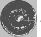
- FIG. 10 is a schematic cross-sectional view for illustrating the method for manufacturing the metal member according to the second embodiment. It is a figure which shows the confirmation result of the joining state by an ultrasonic flaw test (Example). It is a figure which shows the confirmation result of the joining state by an ultrasonic flaw detection test (comparative example).
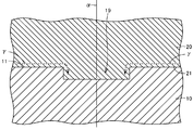
- FIG. 1 is a schematic cross-sectional view showing the structure of a metal member (mechanical part) that can be manufactured by the metal member manufacturing method of the present embodiment.
- the metal member 1 has a structure in which a first member 10 made of a first metal and a second member 20 made of a second metal are joined.
- the first member 10 has a cylindrical shape. One end surface 11 of the first member 10 is a joint surface with the second member 20.
- the second member 20 has a cylindrical shape (disc shape). One end surface 21 of the second member 20 is a joint surface with the first member 10.
- the second metal constituting the second member 20 has a lower deformation resistance than the first metal constituting the first member 10.
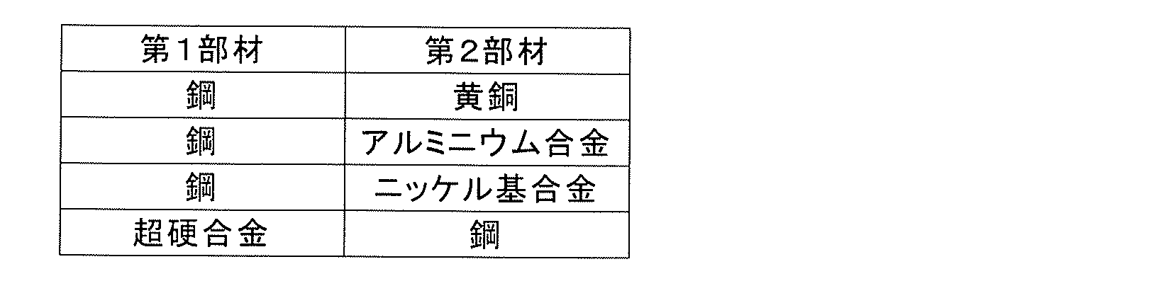
- the first metal for example, tempered (quenched and tempered) steel (for example, alloy steel for mechanical structure such as JIS standard SCM440 or carbon steel for mechanical structure) is adopted. Is done. A copper alloy (for example, high-strength brass) is employed as the second metal.
- a recess 19 is formed on one end surface 11 of the first member 10 so as to include a region intersecting the central axis C of the first member 10.
- the inside of the hollow portion 19 is filled with the second member 20.
- Such a metal member 1 can be manufactured by the manufacturing method of the metal member in this Embodiment as follows.
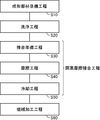
- FIG. 2 is a flowchart showing an outline of a method for manufacturing a metal member.
- FIG. 3 is a schematic view showing the structure of a metal member manufacturing apparatus.
- FIG. 4 is a schematic cross-sectional view showing the operation of the metal member manufacturing apparatus.
- FIG. 5 is a schematic plan view showing the structure of a mold included in the metal member manufacturing apparatus.
- FIG. 6 is a schematic cross-sectional view for explaining a method for producing a metal member.
- a forming member preparation step is performed as a step (S10).
- a cylindrical first member 10 made of tempered alloy steel for machine structure and a disk-shaped second member 20 made of high-strength brass are provided. Be prepared.
- One end surface 11 of the first member 10 is a first contact surface to be a bonding surface.
- a recess 19 is formed in one end surface 11.
- One end surface 21 of the second member 20 is a second contact surface that is a flat surface to be a bonding surface.
- a cleaning step is performed as a step (S20).
- the first member 10 and the second member 20 prepared in the step (S10) are cleaned.
- the first member 10 and the second member 20 are cleaned using a liquid such as methanol, ethanol, or acetone.
- a liquid such as methanol, ethanol, or acetone.
- the closed friction joining process includes a joining preparation process, a friction process, and a cooling process.
- a metal member manufacturing apparatus that manufactures the metal member 1 by performing closed friction welding will be described.
- a closed friction welding apparatus 9 as a metal member manufacturing apparatus includes a main shaft 95 that can rotate around an axis ⁇ , and a base that is spaced from the main shaft 95 in the direction of the axis ⁇ .
- a drive unit 97 that adjusts the distance between the main shaft 95 and the base unit 98 by driving the main shaft 95 in the direction of the axis ⁇ , and a frame 90 that supports the main shaft 95 and the base unit 98.
- a shaft 90 ⁇ / b> A extending in parallel with the axis ⁇ is installed in the frame 90.
- the shaft 90A supports a main shaft support portion 90C that supports the main shaft 95 so as to be movable along the extending direction of the shaft 90A.
- a main shaft moving motor 90B for driving the shaft 90A is connected to the shaft 90A.
- the shaft 90A is driven by the main shaft moving motor 90B, the main shaft 95 supported by the main shaft support portion 90C moves in the axis ⁇ direction. Thereby, the space
- the shaft 90 ⁇ / b> A, the spindle support part 90 ⁇ / b> C, and the spindle movement motor 90 ⁇ / b> B constitute a drive part 97.
- the cavity side wall 93C defining the cavity 93A is formed.
- the rotation side chuck 94 and the mold 93 are arranged so as to surround the outer periphery of one end surface 21 as a second contact surface that is a surface in contact with the first member 10 in the second member 20. Referring to FIG. 4, the height of cavity side wall 93 ⁇ / b> C in the direction of axis ⁇ is greater than the thickness of second member 20.
- the main shaft 95 is provided with a rotation side chuck 94 as a first holding portion that holds the first member 10 so as to face the base portion 98.
- the main shaft 95 is connected to a main shaft motor 95B that rotates the main shaft 95 about the axis ⁇ .
- a load sensor 96 that detects a contact load between the first member 10 and the second member 20 is installed on the main shaft 95.
- the load sensor 96 detects the contact load between the first member 10 and the second member 20 from the magnitude of the reaction force between the first member 10 and the second member 20 applied to the rotation side chuck 94.
- the load sensor 96 is not an indispensable component in the closed friction welding apparatus 9, but by installing this, it becomes easy to adjust the contact load between the first member 10 and the second member 20 to an appropriate range. .
- a mold 93 as a second holding portion that holds the second member 20 is disposed on the base portion 98 so as to face the rotation side chuck.
- base portion 98 includes a base body 91, a mold holder 92, and a mold 93.
- the base body 91 is installed on the frame 90.
- the mold holder 92 is fixed on the base body 91.
- the mold 93 is fitted in a mold holding portion which is a recess formed in the mold holder 92 and is fixed by a radial chuck surface 92B.
- the mold 93 can be separated into two parts 99, 99 as shown in FIG.
- the mold 93 includes a cavity bottom wall 93B that is a circular plane, and a cavity sidewall that extends from the cavity bottom wall 93B in a direction (vertical direction) intersecting the cavity bottom wall 93B. 93C.
- Cavity bottom wall 93B and cavity side wall 93C define cavity 93A.
- the cavity side wall 93C is connected to the outer periphery of the cavity bottom wall 93B having a circular shape, and has a cylindrical surface shape having the same diameter as the cavity bottom wall 93B.
- step (S ⁇ b> 30) the first member 10 is held by the rotation side chuck 94 on the outer peripheral surface.
- the second member 20 is set in the cavity 93 ⁇ / b> A of the mold 93.
- One end face 21 of the second member 20 is surrounded by the cavity side wall 93C.
- the second member 20 is arranged so as to contact the cavity bottom wall 93B defining the cavity 93A at the end face.
- the one end surface 11 of the first member 10 and the one end surface 21 of the second member 20 face each other, and the central axes of the first member 10 and the second member 20 coincide with the rotation axis ⁇ of the rotation side chuck.
- the first member 10 and the second member 20 are disposed.
- On one end surface 11 that is the first contact surface, a recess 19 is formed so as to include a region intersecting with the rotation axis ⁇ .
- the hollow portion 19 has a disk shape whose central axis coincides with the rotation axis ⁇ . In plan view (as viewed from the direction of the rotation axis ⁇ ), the rotation axis ⁇ is located in the recess 19.
- a mold release agent is introduced into the cavity 93A. Thereby, the first member 10 and the second member 20 are heated in a state in which the release agent is present in the cavity 93A in the step (S40) described later.
- the introduction of the release agent is not an essential procedure, but by introducing the release agent, a structure configured by joining the first member 10 and the second member 20 in a later-described step (S50). It becomes easy to remove from the mold 93.
- the release agent may be liquid or powder.
- a friction process is performed as a process (S40).
- the main shaft 95 is driven by the main shaft motor 95B to rotate around the axis ⁇ and is driven by the main shaft moving motor 90B to approach the base portion 98.
- the rotation-side chuck 94 approaches the mold 93 while rotating around the axis ⁇ .
- the first member 10 rotates relatively around the rotation axis ⁇ without changing the relative positional relationship with the second member 20 while being pressed against the second member 20.
- the temperature of the contact portion between the first member 10 and the second member 20 rises due to frictional heat.
- the first member 10 and the second member 20 are heated by this frictional heat.
- the temperature of the 2nd member 20 rises to the temperature below the melting point of the 2nd metal which comprises the 2nd member 20, for example, and below melting
- the deformation resistance of the second member 20 is smaller than the deformation resistance of the first member 10.
- the heated second member 20 is softened and deformed, and comes into contact with the cavity side wall 93 ⁇ / b> C of the mold 93.
- transformation of the 2nd member 20 is also suppressed. Therefore, further heat is generated due to friction between the first member 10 and the second member 20, and the generated heat is suppressed from being released from the cavity 93A.
- a cooling step is performed as a step (S50).
- step (S50) first, the rotational speed of the main shaft 95 is reduced and stopped. Thereafter, the pressing load detected by the load sensor 96 is reduced. During this time, the first member 10 and the second member 20 are cooled while maintaining a state where they are pressed against each other. The first member 10 and the second member 20 are cooled in contact with each other. Thereby, the 1st member 10 and the 2nd member 20 are joined directly.
- the metal member 1 which is a structure formed by joining the first member 10 and the second member 20, is taken out from the closed friction joining apparatus 9.
- the closed friction joining process is completed by the above procedure.
- a machining process is performed as a process (S60).
- machining is performed on the metal member 1 obtained in the step (S50).
- burrs formed by deforming the second member 20 in the step (S40) are removed. Thereafter, heat treatment, finishing, and the like are performed as necessary to complete the metal member 1.
- the peripheral speed of the first member 10 relative to the second member 20 decreases as the rotation axis ⁇ is approached.
- the heat generated by the friction between the first member 10 and the second member 20 decreases as the rotation axis ⁇ is approached.
- the diameter of the 1st member 10 is large, the temperature difference of an outer peripheral part and a center part becomes large. Therefore, even when the temperature rise suitable for joining is achieved at the outer peripheral portion, the temperature rise is insufficient at the central portion, and good joining may be difficult.
- a recess 19 is formed on one end surface 11 of the first member 10.
- heated and softened second member 20 flows along arrow ⁇ and is formed in depression 19 formed so as to include a region intersecting with rotation axis ⁇ . invade.
- heat is supplied to the central portion (region including the rotation axis ⁇ ).
- the temperature difference of an outer peripheral part and a center part becomes small. As a result, it is easy to achieve good bonding over the entire bonding surface.
- the first member 10 made of the first metal and the second metal having a deformation resistance smaller than that of the first metal.
- the metal member 1 which has the structure where the 2nd member 20 which consists of was directly joined firmly can be manufactured.
- a metal member 1 having a structure in which members made of different metals are directly and firmly joined to each other is manufactured.
- FIG. 7 is a schematic cross-sectional view showing the structure of a metal member (mechanical part) that can be manufactured by the metal member manufacturing method of the second embodiment.
- the metal member 1 has a structure in which a first member 10 made of a first metal and a second member 20 made of a second metal are joined.
- the first member 10 has a cylindrical shape (disc shape). One end surface 11 of the first member 10 is a joint surface with the second member 20.
- the second member 20 has a cylindrical shape. One end surface 21 of the second member 20 is a joint surface with the first member 10.
- the second metal constituting the second member 20 has a lower deformation resistance than the first metal constituting the first member 10. As the first metal and the second metal, the same metals as in the first embodiment are employed.
- a recess 19 is formed on one end surface 11 of the first member 10 so as to include a region intersecting the central axis C of the first member 10.
- the inside of the hollow portion 19 is filled with the second member 20.
- Such a metal member 1 can be manufactured by the manufacturing method of the metal member in this Embodiment as follows.
- FIG. 2 is a flowchart showing an outline of a method for manufacturing a metal member.
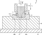
- FIG. 8 is a schematic view showing the structure of a metal member manufacturing apparatus.
- FIG. 9 is a schematic cross-sectional view showing the operation of the metal member manufacturing apparatus.
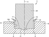
- 10 to 12 are schematic cross-sectional views for explaining a method for producing a metal member.
- a forming member preparation step is performed as a step (S10).
- a first member 10 made of tempered alloy steel for machine structure and a second member 20 made of high-strength brass are prepared.
- the second member 20 has a cylindrical shape.
- the first member 10 has a cylindrical shape (disk shape).
- the first member 10 has a recess 10A.
- the recess 10 ⁇ / b> A is formed so as to include the central axis of the first member 10.
- the recess 10A has a cylindrical shape.
- the central axis of the first member 10 coincides with the central axis of the recess 10A.
- the first member 10 includes a concave bottom surface 11 that defines the concave portion 10 ⁇ / b> A, and a concave side surface 12 that defines the concave portion 10 ⁇ / b> A and extends in a direction intersecting the concave bottom surface 11.
- the recess bottom surface 11 of the first member 10 is a first contact surface to be joined to the second member 20.
- a recess 19 is formed in the bottom surface 11 of the recess.
- the recess 19 is formed in the recess 11.
- One end surface 21 of the second member 20 is a second member contact surface that is a flat surface to be joined to the first member 10.
- a cleaning step is performed as a step (S20).
- This step (S20) is performed in the same manner as in the first embodiment.
- FIG. One end surface 21 of the second member 20 may be in a cut state.
- the closed friction joining process includes a joining preparation process, a friction process, and a cooling process.
- a metal member manufacturing apparatus that manufactures the metal member 1 by performing closed friction welding will be described.
- a closed friction joining apparatus 9 which is a metal member manufacturing apparatus in the second embodiment basically has the same structure as that in the first embodiment and operates in the same manner.
- differences from the first embodiment will be described.
- the main shaft 95 is provided with a rotation side chuck 94 that holds the second member 20 so as to face the base portion 98.
- a fixed side chuck 92 that holds the first member 10 is disposed on the base portion 98 so as to face the rotation side chuck 94.
- the base portion 98 includes a base body 91 and a fixed side chuck 92.
- the fixed side chuck 92 is fixed on the base body 91.
- the stationary chuck 92 includes a bottom surface 92A that holds the first member 10 in the axial direction, and a radial chuck surface 92B that holds the first member 10 in the radial direction.
- step (S30) second member 20 is held by rotation-side chuck 94 on the outer peripheral surface. Further, the first member 10 is held by the fixed side chuck 92 on the outer peripheral surface.
- the concave bottom surface 11 of the first member 10 and one end surface 21 of the second member 20 face each other, and the central axes of the first member 10 and the second member 20 coincide with the rotational axis ⁇ of the rotation side chuck 94.
- the first member 10 and the second member 20 are disposed.
- a recess 19 is formed in the bottom surface 11 of the recess, which is the first contact surface, so as to include a region intersecting with the rotation axis ⁇ .
- the hollow portion 19 has a disk shape whose central axis coincides with the rotation axis ⁇ .
- a friction process is performed as a process (S40).
- the main shaft 95 is driven by the main shaft motor 95B to rotate around the axis ⁇ and is driven by the main shaft moving motor 90B to approach the base portion 98.
- the rotation-side chuck 94 approaches the fixed-side chuck 92 while rotating around the axis ⁇ .
- the second member 20 is formed in the first member 10 without changing the relative position with respect to the first member 10 in a state in which at least a part (region including one end surface 21) enters the recess 10 ⁇ / b> A.
- the one member 10 rotates relatively while being pressed with a predetermined load.
- the second member 20 rotates while being relatively pressed against the concave bottom surface 11 of the first member 10. Thereby, the temperature of the 1st member 10 and the 2nd member 20 rises by friction heat.
- a gap is formed between the outer peripheral surface 22 of the second member 20 and the concave side surface 12 of the first member 10.
- the outer peripheral surface 22 of the second member 20 and the recess side surface 12 of the first member 10 do not contact each other.
- the peripheral speed of the second member 20 relative to the first member 10 decreases as the rotation axis ⁇ is approached.
- the heat generated by the friction between the first member 10 and the second member 20 decreases as the rotation axis ⁇ is approached.
- the diameter of the 2nd member 20 is large, the temperature difference of an outer peripheral part and a center part becomes large. Therefore, even when the temperature rise suitable for joining is achieved at the outer peripheral portion, the temperature rise may be insufficient at the center portion.
- a recess 19 is formed on the bottom surface 11 of the recess of the first member 10. Further, the deformation resistance of the second member 20 is smaller than the deformation resistance of the first member 10. Referring to FIG. 10, in the present embodiment, heated and softened second member 20 flows along arrow ⁇ and is formed in depression 19 formed so as to include a region intersecting with rotation axis ⁇ . invade.
- the heated second member 20 is softened and deformed, and comes into contact with the recess side surface 12.
- the deformation of the second member 20 is limited by the wall surfaces (the concave bottom surface 11 and the concave side surface 12) that define the concave portion 10A of the first member 10. Therefore, the heat generated by the friction is suppressed from being released from the inside of the recess 10A.
- the recess 10A is filled with the softened second member 20. As the second member 20 is deformed, a burr 29 is formed.
- a cooling step is performed as a step (S50).
- step (S50) first, the rotational speed of the main shaft 95 is reduced and stopped. Thereafter, the pressing load detected by the load sensor 96 is reduced. During this time, the first member 10 and the second member 20 are cooled while maintaining a state where they are pressed against each other. The first member 10 and the second member 20 are cooled in contact with each other. Thereby, the 1st member 10 and the 2nd member 20 are joined.
- the metal member 1 which is a structure formed by joining the first member 10 and the second member 20 is taken out from the closed friction joining apparatus 9 (see FIG. 12).
- the closed friction joining process is completed by the above procedure.
- step (S60) machining such as cutting is performed on the metal member 1 obtained in step (S50).
- step (S60) burrs 29 formed by deforming second member 20 in step (S40) while first member 10 and second member 20 are joined are removed.
- step (S60) first member 10 is processed such that concave side surface 12 is removed while first member 10 and second member 20 are joined.
- the outer peripheral region including the concave side surface 12 and the burr 29 are removed.
- the metal member 1 which is a joined body of the first member 10 and the second member 20 shown in FIG. 7 is obtained.
- the removal of the outer peripheral region including the concave side surface 12 and the removal of the burr 29 may be performed continuously as one process, or may be performed as a separate process with time. Thereafter, heat treatment, finishing, and the like are performed as necessary to complete the metal member 1.
- the second member 20 softened in the step (S40) enters the hollow portion 19, whereby heat is supplied to the central portion (region including the rotation axis ⁇ ). Thereby, the temperature difference of an outer peripheral part and a center part becomes small. As a result, it is easy to achieve good bonding over the entire bonding surface.
- the first member 10 made of the first metal and the second metal having a deformation resistance smaller than that of the first metal.
- the metal member 1 which has the structure where the 2nd member 20 which consists of was directly joined firmly can be manufactured.
- the metal member 1 having a structure in which the first member 10 and the second member 20 made of different metals are directly and strongly bonded to each other can be manufactured.
- the deformation resistance of the second member 20 (second metal) in a state where the temperature is increased is compared with the deformation resistance of the first member 10 (first metal). It is preferably 10% or smaller, more preferably 50% or smaller, and further preferably 80% or smaller. As described above, when the deformation resistance of the second member 20 (second metal) is smaller than that of the first member 10 (first metal), the first member 10 and the second member 20 as in the present embodiment Can be joined. However, when the difference between the deformation resistance of the first member 10 and the deformation resistance of the second member 20 is small, not only the second member 20 but also the first member 10 may be deformed in the step (S40).
- step (S40) it is necessary to strictly control the temperatures of the first member 10 and the second member 20.
- step (S40) by setting the deformation resistance of the second metal in a state where the temperature is increased to be 10% or more smaller than the deformation resistance of the first metal, it becomes easy to achieve good bonding and 50% By setting it smaller than this, and further setting it smaller than 80%, it becomes easier to achieve good bonding.
- FIGS. 13 and 14 are images corresponding to a cross section parallel to the joint surface between the first member 10 and the second member 20.
- the white area is an area where a defect is detected.
- an unjoined region D is formed near the center of the joint surface.
- the peripheral speed of the first member 10 relative to the second member 20 decreases as the rotation axis ⁇ is approached.
- the heat generated by the friction between the first member 10 and the second member 20 decreases as the rotation axis ⁇ is approached.
- the diameter of the first member 10 is large as in the present sample (diameter 127 mm)
- the temperature difference between the outer peripheral portion and the central portion increases. Therefore, even when the temperature rise suitable for joining is achieved at the outer peripheral portion, the temperature rise is insufficient at the central portion, and it is considered that good joining cannot be achieved.
- the heated and softened second member 20 flows and enters the recess 19.
- heat is supplied to the central portion (region including the rotation axis ⁇ ).
- the temperature difference of an outer peripheral part and a center part becomes small.
- FIG. 15 shows a photograph of the vicinity of the interface between the first member 10 and the second member 20 in the vicinity of the end portion in the radial direction of the hollow portion 19.
- a photograph of the vicinity of the interface between the first member 10 and the second member 20 in the vicinity of the center in the radial direction of the hollow portion 19 is shown in FIG.
- a metal member having a structure in which members made of different metals are directly joined can be manufactured.
- a metal member having a large diameter is manufactured, it is effective to apply the present invention in which a recess is formed in the first member.
- the time required for joining the first member and the second member is about 10 seconds, and joining in a short time is possible.
- the method for producing a metal member of the present invention can be particularly advantageously applied to the production of a metal member having a structure in which members made of different metals are directly joined to each other.
Landscapes
- Engineering & Computer Science (AREA)
- Mechanical Engineering (AREA)
- Pressure Welding/Diffusion-Bonding (AREA)
- Forging (AREA)
Abstract
Description
図1は、本実施の形態の金属部材の製造方法により製造可能な金属部材(機械部品)の構造を示す概略断面図である。図1を参照して、金属部材1は、第1金属からなる第1部材10と第2金属からなる第2部材20とが接合された構造を有している。
次に、本発明の他の実施の形態である実施の形態2について説明する。図7は、実施の形態2の金属部材の製造方法により製造可能な金属部材(機械部品)の構造を示す概略断面図である。図7を参照して、金属部材1は、第1金属からなる第1部材10と第2金属からなる第2部材20とが接合された構造を有している。
Claims (12)
- 第1金属からなる第1部材と、前記第1金属よりも変形抵抗の小さい第2金属からなる第2部材と、を準備する工程と、
前記第1部材と前記第2部材とを接合する工程と、を備え、
前記第1部材と前記第2部材とを接合する工程は、
前記第1部材と前記第2部材とを互いに押し付け、前記第1部材および前記第2部材を相対的な位置関係を変えることなく回転軸周りに相対的に回転させることにより、前記第1部材および前記第2部材を加熱する工程と、
加熱された前記第1部材と前記第2部材とを互いに押し付けた状態で冷却する工程と、を含み、
前記第1部材および前記第2部材を加熱する工程において前記第1部材の前記第2部材に接触する表面である第1接触面には、前記回転軸と交差する領域を含むように窪み部が形成されている、金属部材の製造方法。 - 前記第1部材および前記第2部材を加熱する工程では、金型のキャビティ内に前記第2部材が配置される、請求項1に記載の金属部材の製造方法。
- 前記金型は、
前記キャビティを規定するキャビティ底壁と、
前記キャビティを規定し、前記キャビティ底壁に交差する方向に延在するキャビティ側壁と、を含む、請求項2に記載の金属部材の製造方法。 - 前記第1部材および前記第2部材を加熱する工程では、前記第2部材において前記第1部材に接触する面である第2接触面が、前記キャビティ側壁に取り囲まれる、請求項3に記載の金属部材の製造方法。
- 前記第1部材および前記第2部材を加熱する工程では、前記金型を固定し、前記第1部材を回転させる、請求項2~4のいずれか1項に記載の金属部材の製造方法。
- 前記第1部材には凹部が形成されており、
前記窪み部は前記凹部内に形成されており、
前記第1部材および前記第2部材を加熱する工程では、前記第2部材を、少なくとも一部が前記凹部に進入する状態で前記第1部材に相対的に押し付けつつ回転させることにより、前記第1部材および前記第2部材を加熱する、請求項1に記載の金属部材の製造方法。 - 前記第1部材は、
前記凹部を規定する凹部底面と、
前記凹部を規定し、前記凹部底面に交差する方向に延びる凹部側面と、を含み、
前記第1部材および前記第2部材を加熱する工程では、前記第1部材の前記凹部底面に前記第2部材が相対的に押し付けられつつ回転する、請求項6に記載の金属部材の製造方法。 - 前記第1部材および前記第2部材を加熱する工程では、前記第2部材が変形することにより前記凹部側面に接触する、請求項6または7に記載の金属部材の製造方法。
- 前記第1部材と前記第2部材とが接合した状態で前記凹部側面が除去されるように前記第1部材が加工される工程をさらに備える、請求項6~8のいずれか1項に記載の金属部材の製造方法。
- 前記第1部材および前記第2部材を加熱する工程では、前記第1部材を固定し、前記第2部材を回転させる、請求項6~9のいずれか1項に記載の金属部材の製造方法。
- 前記第1部材と前記第2部材とが接合した状態で、前記第1部材および前記第2部材を加熱する工程において前記第2部材が変形して形成されたバリを除去する工程をさらに備える、請求項1~10のいずれか1項に記載の金属部材の製造方法。
- 前記第1部材および前記第2部材を加熱する工程において、温度が上昇した状態における前記第2金属の変形抵抗は前記第1金属の変形抵抗に比べて10%以上小さい、請求項1~11のいずれか1項に記載の金属部材の製造方法。
Priority Applications (6)
| Application Number | Priority Date | Filing Date | Title |
|---|---|---|---|
| CN201580078839.XA CN107427956A (zh) | 2015-04-15 | 2015-04-15 | 金属部件的制造方法 |
| JP2017512127A JP6553717B2 (ja) | 2015-04-15 | 2015-04-15 | 金属部材の製造方法 |
| KR1020177029307A KR101965735B1 (ko) | 2015-04-15 | 2015-04-15 | 금속 부재의 제조 방법 |
| DE112015006449.4T DE112015006449B4 (de) | 2015-04-15 | 2015-04-15 | Verfahren zum Herstellen eines Metallelementes |
| US15/560,311 US10618130B2 (en) | 2015-04-15 | 2015-04-15 | Method for producing metal member |
| PCT/JP2015/061593 WO2016166843A1 (ja) | 2015-04-15 | 2015-04-15 | 金属部材の製造方法 |
Applications Claiming Priority (1)
| Application Number | Priority Date | Filing Date | Title |
|---|---|---|---|
| PCT/JP2015/061593 WO2016166843A1 (ja) | 2015-04-15 | 2015-04-15 | 金属部材の製造方法 |
Publications (1)
| Publication Number | Publication Date |
|---|---|
| WO2016166843A1 true WO2016166843A1 (ja) | 2016-10-20 |
Family
ID=57127025
Family Applications (1)
| Application Number | Title | Priority Date | Filing Date |
|---|---|---|---|
| PCT/JP2015/061593 Ceased WO2016166843A1 (ja) | 2015-04-15 | 2015-04-15 | 金属部材の製造方法 |
Country Status (6)
| Country | Link |
|---|---|
| US (1) | US10618130B2 (ja) |
| JP (1) | JP6553717B2 (ja) |
| KR (1) | KR101965735B1 (ja) |
| CN (1) | CN107427956A (ja) |
| DE (1) | DE112015006449B4 (ja) |
| WO (1) | WO2016166843A1 (ja) |
Families Citing this family (4)
| Publication number | Priority date | Publication date | Assignee | Title |
|---|---|---|---|---|
| WO2016150342A1 (zh) | 2015-03-20 | 2016-09-29 | 杨达志 | 多糖-聚氨共聚物及其在降低血浆中低密度脂蛋白浓度的应用 |
| JP6506791B2 (ja) * | 2017-03-29 | 2019-04-24 | Kyb−Ys株式会社 | 接合体の製造方法及び接合体 |
| DE112019004864T5 (de) * | 2018-09-27 | 2021-06-10 | Kyb-Ys Co., Ltd. | Herstellungsverfahren eines Verbindungskörpers |
| CN113967784B (zh) * | 2021-11-22 | 2022-05-13 | 中国兵器工业第五九研究所 | 一种大尺寸铝-钢反应辅热增韧摩擦焊接方法 |
Citations (4)
| Publication number | Priority date | Publication date | Assignee | Title |
|---|---|---|---|---|
| JPS60187486A (ja) * | 1984-03-06 | 1985-09-24 | Matsushita Electric Ind Co Ltd | 金属部材の接合方法 |
| JPH1089241A (ja) * | 1996-09-17 | 1998-04-07 | Hitachi Constr Mach Co Ltd | 斜板式液圧回転機 |
| JP2000301364A (ja) * | 1999-04-12 | 2000-10-31 | Mitsuo Tsukada | 異種金属材料の回転摩擦圧接方法 |
| US20070272728A1 (en) * | 2004-03-10 | 2007-11-29 | Mtu Aero Engines Gmbh | Apparatus and Method for Rotary Friction Welding |
Family Cites Families (19)
| Publication number | Priority date | Publication date | Assignee | Title |
|---|---|---|---|---|
| US3040427A (en) * | 1958-08-29 | 1962-06-26 | Howell Stanley | Method of uniting copper and aluminum tubes |
| US3144710A (en) * | 1961-05-01 | 1964-08-18 | American Mach & Foundry | Friction sealing |
| US3452421A (en) * | 1964-03-13 | 1969-07-01 | Caterpillar Tractor Co | Friction welding of dissimilar materials |
| US3444611A (en) * | 1966-02-25 | 1969-05-20 | Ford Motor Co | Friction welding method |
| GB1277579A (en) | 1968-07-15 | 1972-06-14 | Wellworthy Ltd | Pistons |
| JPS5870989A (ja) | 1981-10-22 | 1983-04-27 | Nissan Motor Co Ltd | 異種部材の接合方法 |
| DE3626009A1 (de) | 1985-08-06 | 1987-02-12 | Kuka Schweissanlagen & Roboter | Verfahren zum verbinden von metallischen koerpern mit anderen metallischen oder nichtmetallischen, insbesondere keramischen teilen |
| US5154340A (en) | 1991-07-02 | 1992-10-13 | Peacock Harold B | Method and device for frictional welding |
| JPH0663775A (ja) | 1992-08-21 | 1994-03-08 | Kuroishi Tekko Kk | 環状部材と軸状部材とを接合する方法 |
| JPH09122935A (ja) | 1995-10-26 | 1997-05-13 | Ishikawajima Harima Heavy Ind Co Ltd | アルミ体と鉄系軸との接合方法および接合体 |
| JP2000343246A (ja) * | 1999-06-03 | 2000-12-12 | Mitsubishi Motors Corp | 軸状部材の摩擦圧接部構造及び摩擦圧接方法 |
| CN1114514C (zh) * | 2000-07-19 | 2003-07-16 | 中国科学院金属研究所 | 一种异金属接头的制造方法 |
| JP2002178167A (ja) * | 2000-12-08 | 2002-06-25 | Fuji Oozx Inc | Ti合金とTi−Al系金属間化合物との接合方法及びこの方法により形成したエンジンバルブ |
| JP2002113583A (ja) | 2000-10-10 | 2002-04-16 | Kogi Corp | 摩擦圧接方法 |
| US6691910B2 (en) * | 2000-12-08 | 2004-02-17 | Fuji Oozx, Inc. | Method of joining different metal materials by friction welding |
| DE10330188A1 (de) * | 2003-07-03 | 2005-02-03 | Kuka Schweissanlagen Gmbh | Verfahren und Vorrichtung zum Pressschweißen |
| US20050218192A1 (en) * | 2004-03-31 | 2005-10-06 | Jeff Lovin | Method and system of inertia friction welding |
| FR2903921B1 (fr) * | 2006-07-19 | 2009-06-05 | Snecma Sa | Procede de fabrication d'un disque aubage monobloc et moule pour la mise en oeuvre du procede |
| WO2015140647A2 (en) * | 2014-03-11 | 2015-09-24 | Eaton Capital | Method for manufacturing a gear |
-
2015
- 2015-04-15 DE DE112015006449.4T patent/DE112015006449B4/de active Active
- 2015-04-15 WO PCT/JP2015/061593 patent/WO2016166843A1/ja not_active Ceased
- 2015-04-15 JP JP2017512127A patent/JP6553717B2/ja not_active Expired - Fee Related
- 2015-04-15 US US15/560,311 patent/US10618130B2/en active Active
- 2015-04-15 KR KR1020177029307A patent/KR101965735B1/ko not_active Expired - Fee Related
- 2015-04-15 CN CN201580078839.XA patent/CN107427956A/zh active Pending
Patent Citations (4)
| Publication number | Priority date | Publication date | Assignee | Title |
|---|---|---|---|---|
| JPS60187486A (ja) * | 1984-03-06 | 1985-09-24 | Matsushita Electric Ind Co Ltd | 金属部材の接合方法 |
| JPH1089241A (ja) * | 1996-09-17 | 1998-04-07 | Hitachi Constr Mach Co Ltd | 斜板式液圧回転機 |
| JP2000301364A (ja) * | 1999-04-12 | 2000-10-31 | Mitsuo Tsukada | 異種金属材料の回転摩擦圧接方法 |
| US20070272728A1 (en) * | 2004-03-10 | 2007-11-29 | Mtu Aero Engines Gmbh | Apparatus and Method for Rotary Friction Welding |
Also Published As
| Publication number | Publication date |
|---|---|
| CN107427956A (zh) | 2017-12-01 |
| US20180056438A1 (en) | 2018-03-01 |
| KR101965735B1 (ko) | 2019-04-04 |
| JPWO2016166843A1 (ja) | 2018-02-08 |
| JP6553717B2 (ja) | 2019-07-31 |
| DE112015006449T5 (de) | 2018-01-18 |
| KR20170125100A (ko) | 2017-11-13 |
| US10618130B2 (en) | 2020-04-14 |
| DE112015006449B4 (de) | 2024-02-01 |
Similar Documents
| Publication | Publication Date | Title |
|---|---|---|
| JP6553717B2 (ja) | 金属部材の製造方法 | |
| JP6553716B2 (ja) | 金属部材の製造方法 | |
| JP6159815B2 (ja) | 摺動部品、摺動部品の製造方法および摺動部品の製造装置 | |
| JP6449444B2 (ja) | 金属部材の製造方法 | |
| JP6653974B2 (ja) | 機械部品およびその製造方法 | |
| EP3159567A1 (en) | Constant velocity universal joint outer joint member and manufacturing method for same | |
| JP6383423B2 (ja) | 金属部材の製造装置 | |
| JP6553715B2 (ja) | 金属部材の製造方法 |
Legal Events
| Date | Code | Title | Description |
|---|---|---|---|
| 121 | Ep: the epo has been informed by wipo that ep was designated in this application |
Ref document number: 15889181 Country of ref document: EP Kind code of ref document: A1 |
|
| WWE | Wipo information: entry into national phase |
Ref document number: 15560311 Country of ref document: US |
|
| ENP | Entry into the national phase |
Ref document number: 2017512127 Country of ref document: JP Kind code of ref document: A |
|
| ENP | Entry into the national phase |
Ref document number: 20177029307 Country of ref document: KR Kind code of ref document: A |
|
| WWE | Wipo information: entry into national phase |
Ref document number: 112015006449 Country of ref document: DE |
|
| 122 | Ep: pct application non-entry in european phase |
Ref document number: 15889181 Country of ref document: EP Kind code of ref document: A1 |