WO2016163088A1 - エンジン冷却システムの制御装置 - Google Patents
エンジン冷却システムの制御装置 Download PDFInfo
- Publication number
- WO2016163088A1 WO2016163088A1 PCT/JP2016/001667 JP2016001667W WO2016163088A1 WO 2016163088 A1 WO2016163088 A1 WO 2016163088A1 JP 2016001667 W JP2016001667 W JP 2016001667W WO 2016163088 A1 WO2016163088 A1 WO 2016163088A1
- Authority
- WO
- WIPO (PCT)
- Prior art keywords
- learning
- valve
- path
- coolant
- valve closing
- Prior art date
- Legal status (The legal status is an assumption and is not a legal conclusion. Google has not performed a legal analysis and makes no representation as to the accuracy of the status listed.)
- Ceased
Links
Images




Classifications
-
- F—MECHANICAL ENGINEERING; LIGHTING; HEATING; WEAPONS; BLASTING
- F01—MACHINES OR ENGINES IN GENERAL; ENGINE PLANTS IN GENERAL; STEAM ENGINES
- F01P—COOLING OF MACHINES OR ENGINES IN GENERAL; COOLING OF INTERNAL-COMBUSTION ENGINES
- F01P7/00—Controlling of coolant flow
- F01P7/14—Controlling of coolant flow the coolant being liquid
- F01P7/16—Controlling of coolant flow the coolant being liquid by thermostatic control
-
- F—MECHANICAL ENGINEERING; LIGHTING; HEATING; WEAPONS; BLASTING
- F01—MACHINES OR ENGINES IN GENERAL; ENGINE PLANTS IN GENERAL; STEAM ENGINES
- F01P—COOLING OF MACHINES OR ENGINES IN GENERAL; COOLING OF INTERNAL-COMBUSTION ENGINES
- F01P7/00—Controlling of coolant flow
- F01P7/14—Controlling of coolant flow the coolant being liquid
- F01P2007/146—Controlling of coolant flow the coolant being liquid using valves
-
- F—MECHANICAL ENGINEERING; LIGHTING; HEATING; WEAPONS; BLASTING
- F01—MACHINES OR ENGINES IN GENERAL; ENGINE PLANTS IN GENERAL; STEAM ENGINES
- F01P—COOLING OF MACHINES OR ENGINES IN GENERAL; COOLING OF INTERNAL-COMBUSTION ENGINES
- F01P2023/00—Signal processing; Details thereof
- F01P2023/08—Microprocessor; Microcomputer
-
- F—MECHANICAL ENGINEERING; LIGHTING; HEATING; WEAPONS; BLASTING
- F01—MACHINES OR ENGINES IN GENERAL; ENGINE PLANTS IN GENERAL; STEAM ENGINES
- F01P—COOLING OF MACHINES OR ENGINES IN GENERAL; COOLING OF INTERNAL-COMBUSTION ENGINES
- F01P2060/00—Cooling circuits using auxiliaries
-
- F—MECHANICAL ENGINEERING; LIGHTING; HEATING; WEAPONS; BLASTING
- F01—MACHINES OR ENGINES IN GENERAL; ENGINE PLANTS IN GENERAL; STEAM ENGINES
- F01P—COOLING OF MACHINES OR ENGINES IN GENERAL; COOLING OF INTERNAL-COMBUSTION ENGINES
- F01P3/00—Liquid cooling
- F01P3/20—Cooling circuits not specific to a single part of engine or machine
Definitions
- This disclosure relates to a control device for an engine cooling system.
- a technology for controlling an engine to a desired temperature by circulating an engine coolant through a heat recovery unit such as a radiator has been put into practical use. Specifically, by providing a flow rate adjusting valve that adjusts the flow rate of the coolant according to the position of the valve body in the circulation path that circulates the engine coolant through the heat recovery unit, and adjusting the flow rate adjusting valve, The temperature of the engine is controlled (see, for example, Patent Document 1).
- the valve closing position of the flow adjustment valve changes due to individual differences and aging. For this reason, the flow rate of the coolant with respect to the heat recovery unit may be excessive or insufficient due to the shift of the valve closing position of the valve body.
- learning of the valve closing position is performed in order to recognize an accurate valve closing position. In this case, the valve body is gradually opened from the state where the valve body is surely closed, and the valve closing position is learned from the valve body position at the time when the coolant starts to flow.
- the coolant leaks to the heat recovery unit, and there is a possibility that inconveniences such as unintentionally lowering the engine temperature may occur.
- An object of the present disclosure is to provide a control device for an engine cooling system that can appropriately perform learning of the closing position of a flow rate adjustment valve while suppressing an unintended decrease in engine temperature.
- a control device for an engine cooling system includes a flow rate adjustment valve that is provided in a circulation path of an engine coolant and that adjusts the flow rate of the coolant flowing through the circulation path according to the position of the valve body;
- An engine cooling system control device provided with a heat recovery unit that recovers heat of the cooling liquid, wherein the valve body is moved to the valve opening side by a predetermined amount while the flow path for the flow rate adjustment valve is closed to the heat recovery unit.
- the first learning unit that learns the closed position of the flow rate adjustment valve based on the fact that the coolant flows through the circulation path, and the heat recovery in the flow rate adjustment valve after learning the closed position by the first learning unit
- the valve body is moved to the valve opening side by a predetermined amount within the range up to the learning value of the valve closing position with the flow path to the part closed, and if the coolant does not flow through the circulation path, it is decided to maintain the learning value
- To finish the learning of the valve closing position Includes a ⁇ , the.
- the valve body is operated to the valve opening side within a range not exceeding the learning value at that time (previous learning value).
- the learning since the valve body does not operate exceeding the learning value, the learning is not unnecessarily prolonged, and the learning can be completed quickly. Therefore, overheating of the engine due to delay of heat recovery in the heat recovery section can be suppressed.
- the valve body since the valve body is not opened excessively during learning of the valve closing position, it is possible to prevent the heat of the coolant from being recovered excessively in the heat recovery section, which in turn reduces the engine temperature unintentionally. Can be suppressed.
- FIG. 1 is a schematic configuration diagram of an engine cooling system
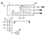
- FIG. 2 is a schematic diagram showing the flow regulating valve in an expanded state
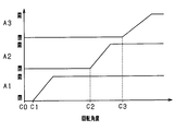
- FIG. 3 is a diagram showing the relationship between the rotation angle of the rotor and the open / closed state of each port
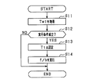
- FIG. 4 is a flowchart showing a processing procedure related to water temperature feedback.
- FIG. 5 is a diagram illustrating the first learning
- FIG. 6 is a diagram illustrating the second learning
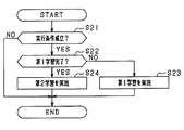
- FIG. 7 is a flowchart showing a processing procedure related to the first learning and the second learning
- FIG. 8 is a time chart showing the result of a simulation experiment related to the second learning.
- a water pump 13 for circulating the cooling water of the engine 11 is provided in the inlet flow path 12 connected to the inlet side of the water jacket (cooling water passage) of the engine 11.
- the water pump 13 is a mechanical water pump that is driven by the power of the engine 11.
- the bypass passage 15 is connected to the outlet passage 14 connected to the outlet side of the water jacket of the engine 11, and the oil cooler passage 16, the heater core passage 17, and the radiator are connected via the flow rate adjustment valve 30.
- the flow path 18 is connected.
- the bypass channel 15 is a channel for circulating the cooling water of the engine 11. Due to the circulation of the cooling water, the engine 11 is warmed up in the cold state.
- An oil cooler (O / C) 19 for cooling oil such as engine oil, a heater core (H / C) 20 for heating, respectively, are provided in the middle of the oil cooler flow path 16, the heater core flow path 17, and the radiator flow path 18.
- a radiator 21 that dissipates heat of the cooling water is provided.
- the oil cooler 19, the heater core 20, and the radiator 21 correspond to the heat recovery unit.
- Each of the flow paths 16 to 18 is a flow path for circulating the cooling water of the engine 11 through each of the heat recovery units 19 to 21. Due to the circulation of the cooling water, heat is recovered from the cooling water heated by the engine 11 in each of the heat recovery units 19 to 21.
- the flow paths 15 to 18 are joined before the water pump 13 and connected to the suction port of the water pump 13.
- the outlet channel 14 is provided with an outlet water temperature sensor 22 that detects an outlet water temperature Tw1, which is the temperature of the cooling water flowing out from the engine 11. Further, an inlet water temperature sensor 23 that detects an inlet water temperature Tw0 that is the temperature of the cooling water flowing into the engine 11 is provided in the inlet flow path 12 of the engine 11. In addition to the outlet water temperature sensor 22 and the inlet water temperature sensor 23, water temperature sensors may be provided in the respective channels 16 to 18.
- the flow rate adjustment valve 30 includes a rotor 31, a sleeve 32, and a motor 33.
- FIG. 2 shows the exploded configuration of the flow rate adjustment valve 30 as well as an exploded view.
- the rotor 31 and the sleeve 32 have a cylindrical shape centered on the axis L, and the rotor 31 is fitted to the inner periphery of the sleeve 32 so as to be relatively rotatable.
- the rotor 31 corresponds to a valve body.
- the rotor 31 includes ports A1, A2, and A3 that connect the outlet channel 14 and the channels 16 to 18.
- Port A1 is an inlet to the oil cooler passage 16
- port A2 is an inlet to the heater core passage 17
- port A3 is an inlet to the radiator passage 18.
- the ports A1 to A3 are arranged at equal intervals in a row on the rotor 31 along the axis L direction, and are arranged in the order of port A1, port A2, and port A3.
- the rotor 31 is rotationally driven by a motor 33, and the rotor 31 rotates relative to the sleeve 32 by energization of the motor 33.
- the sleeve 32 includes slits B1, B2, and B3 extending in the circumferential direction.
- the slits B1 to B3 are arranged along the axis L direction at the same intervals as the ports A1 to A3. Further, the opening lengths of the slits B1 to B3 in the circumferential direction of the sleeve 32 are different. Specifically, in the sleeve 32, the first ends (right side in FIG. 2) of the slits B1 to B3 are aligned along the direction of the axis L, whereas the second ends (in FIG. 2) of the slits B1 to B3. The left side is different, and the opening length is longer in the order of slit B1, slit B2, and slit B3.
- C1 to C3 are angular positions at which the paths corresponding to the respective flow paths 16 to 18 in the flow rate adjusting valve 30 shift from closed to open, and are referred to as valve closing angles C1 to C3.
- the opening ratio of each of the ports A1 to A3 is 0% from C0 that is the starting angle of the rotation operation to the valve closing angle C1, and the cooling water of the engine 11 flows into each of the flow paths 16 to 18. Does not flow.
- the cooling water circulates only through the path of the water jacket of the engine 11 ⁇ the outlet channel 14 ⁇ the bypass channel 15 ⁇ the inlet channel 12 ⁇ the water jacket of the engine 11. In this case, this route is referred to as a first route.
- the port A2 and the slit B2 are communicated with each other through a section where the aperture ratio of A3 is unchanged.
- the port A2 and the slit B2 are communicated.
- the cooling water also circulates in the circulation path via the heater core flow path 17.
- this circulation path is called a second path.
- the opening ratio of the port A2 increases and the coolant flow rate of the heater core channel 17 increases as the rotation angle of the rotor 31 increases.
- the cooling water also circulates in a circulation path that passes through the radiator flow path 18.
- this circulation path is called a second path.
- the opening ratio of the port A3 increases and the cooling water flow rate of the radiator flow path 18 increases.
- the ECU 24 is mainly composed of a microcomputer composed of a well-known CPU, ROM, RAM, and the like, and based on various control programs stored in the ROM, for example, water temperature feedback control (f / b) and flow rate adjustment valve 30 valve closing angle learning is executed.
- the flow rate adjusting valve 30 controls the flow rate of the cooling water flowing through each of the flow paths 16 to 18 so that the outlet water temperature Tw1 detected by the outlet water temperature sensor 22 matches the target temperature Ttg. At this time, the deviation between the outlet water temperatures Tw1 and Ttg is calculated, and the opening degree control of the flow rate adjusting valve 30 is performed based on the opening control amount of the flow rate adjusting valve 30 calculated based on the deviation.
- the outlet water temperature Tw1 is acquired.
- the process of S11 corresponds to an acquisition unit.
- the water temperature feedback control is executed when the outlet water temperature Tw1 is equal to or higher than the target temperature and a predetermined time has elapsed. It is good to be done.
- S13 a target temperature Ttg for the outlet water temperature Tw1 is set.
- S14 water temperature feedback control is performed so that the outlet water temperature Tw1 matches the target temperature Ttg, and this process is terminated.
- the processes of S13 and S14 correspond to a feedback control unit.
- valve closing angle learning in this embodiment will be described.
- the valve closing angles C1 to C3 are learned based on the change in the outlet water temperature Tw1 accompanying the rotation of the rotor 31.
- the rotation angle of the rotor 31 exceeds the valve closing angles C1 to C3
- the cooling water circulates through the flow paths 16 to 18 and the outlet water temperature Tw1 changes. Therefore, the valve closing angles C1 to C3 can be learned by monitoring the outlet water temperature Tw1.
- first learning and second learning are performed as valve closing angle learning.
- the valve closing angle learning has not been performed, only the first learning is performed, and when the first learning has been performed, the second learning is performed.
- the rotation angle of the rotor 31 is changed by a predetermined amount from the angular position (learning start angle ⁇ b) when the flow rate adjustment valve 30 is closed to the valve opening side, and the ports A1 to A3 are changed. Either one is gradually displaced toward the slits B1 to B3. Each amount should be constant.
- every time the rotation angle of the rotor 31 is changed it is determined whether or not the outlet water temperature Tw1 has decreased as the path in the flow rate adjusting valve 30 is opened.
- the rotation angle of the rotor 31 immediately before the outlet water temperature Tw1 decreases is learned as the valve closing angles C1 to C3.
- the outlet water temperature Tw1 decreases every time learning is performed, and therefore, the engine temperature may decrease unintentionally. For this reason, there is a possibility that a delay in warming up of the engine 11 occurs, resulting in deterioration of fuel consumption. Therefore, in the second learning, the valve closing angles C1 to C3 are learned in the range up to the previous learning value acquired by the first learning.
- the second learning will be described with reference to FIG.
- the range in which the rotor 31 is rotated is different from that in the first learning. That is, in the second learning, the rotation angle of the rotor 31 is changed by a predetermined amount toward the valve opening side in the range from the learning start angle ⁇ b to the previous learning value, and any of the ports A1 to A3 is gradually changed to the slits B1 to B3. Displace to the side.
- every time the rotation angle of the rotor 31 is changed it is determined whether or not the outlet water temperature Tw1 has decreased as the path in the flow rate adjusting valve 30 is opened.
- the previous learning value is maintained as it is.
- the learning value is updated with the rotation angle of the rotor 31 immediately before the outlet water temperature Tw1 decreases as the valve closing angles C1 to C3.
- the learning value is updated only when the actual valve closing angles C1 to C3 change to the valve closing side with respect to the previous learning value, and the actual valve closing angles C1 to C3 are temporarily learned.
- the learning value is not updated. Therefore, after the first learning is performed, if the actual valve closing angles C1 to C3 are shifted to the valve opening side with respect to the valve closing angles C1 to C3 recognized as the learning values, the learning value with the deviation generated is obtained. Will be maintained. In this case, when the ports A1 to A3 are opened by rotating the rotor 31 from the state in which the ports A1 to A3 are closed, the dead time until the ports A1 to A3 are actually opened is prolonged.
- the delay in starting the flow of the cooling water to each of the flow paths 16 to 18 may cause an unexpected rise in water temperature.
- the water temperature feedback control is executed as described above, even if an unexpected rise in the water temperature occurs, it can be quickly resolved.
- the execution condition for the first learning or the second learning is satisfied.
- the first learning and the second learning are executed under a situation where the detection accuracy of the outlet water temperature Tw1 is not lowered, and the execution condition includes that the water temperature detection accuracy is not lowered.
- the conditions under which the water temperature detection accuracy does not decrease include that there is no situation where heat generation of the engine 11 is stopped or suppressed, such as when the fuel is decelerated, when the cylinder is deactivated, or during EV travel, or during high-speed travel or when the outside air is in a cold atmosphere. That is, it is not under the environment where the cooling water is lowered.
- the learning execution condition includes that the rotational position of the rotor 31 is in a predetermined section where the aperture ratio of each of the ports A1 to A3 is unchanged at 0% or 100% regardless of the rotation of the rotor 31. ing.
- the execution condition is that the outlet water temperature Tw1 is equal to or higher than the predetermined water temperature Th that is lower than the target temperature Ttg. It should be included.
- the process is terminated, and if YES in S21, the process proceeds to S22.
- S22 it is determined whether or not the first learning is completed and the learning values of the valve closing angles C1 to C3 have already been acquired. If NO in S22, the process proceeds to S23, and a series of processes is performed as the first learning. At this time, the learning values of the valve closing angles C1 to C3 calculated in the first learning are appropriately stored in the memory in the ECU 24.
- the process of S23 corresponds to a first learning unit.
- the process proceeds to S24, and a series of processes is performed as the second learning.
- the second learning if a new learning value is not calculated, the previous learning value is retained, and if a new learning value is calculated, the previous learning value is updated with the new learning value.
- the process of S24 corresponds to a second learning unit.
- FIG. 8 is a time chart showing the results of a simulation experiment related to the second learning.
- FIG. 8 shows the temperature change of the cooling water and the change of the rotor rotation angle with respect to the time change after the engine is started.
- Tw2 is the outlet water temperature of the oil cooler 19
- Tw3 is the outlet water temperature of the heater core 20.
- the opening ratio of the port A1 in the flow rate adjustment valve 30 is controlled by the water temperature feedback control that matches the outlet water temperature Tw1 with the target temperature Ttg.
- the rotor 31 rotates to the valve opening side so that the opening ratio of the port A1 is increased, and accordingly, the cooling water flows into the oil cooler flow path 16, thereby increasing the outlet water temperature Tw2 of the oil cooler 19.
- the port A1 is fully opened (aperture ratio 100%).
- the water temperature feedback control is temporarily stopped, and the second learning L2 for learning the valve closing angle C2 is executed (t6 to t7).
- learning of the valve closing angle C2 is executed by changing the rotation angle of the rotor 31 within the range up to the previous learning value.
- the water temperature feedback control is resumed at timing t8.
- the rotor 31 rotates to the valve opening side so that the opening ratio of the port A2 is increased, and accordingly, the cooling water flows into the heater core channel 17, whereby the outlet water temperature Tw3 of the heater core 20 rises.
- the port A2 is completely opened (aperture ratio 100%).
- the water temperature feedback control is temporarily stopped, and the second learning L3 for learning the valve closing angle C3 is executed (t10 to t11).
- the valve closing angle C3 is learned by changing the rotation angle of the rotor 31 within the range up to the previous learning value.
- the water temperature feedback control is resumed at timing t12.
- the rotor 31 rotates to the valve opening side so that the opening ratio of the port A3 is increased, and the cooling water flows into the radiator flow path 18 accordingly.
- the port A3 is completely opened (aperture ratio 100%).
- the operation of the rotor 31 toward the valve opening side is performed within a range not exceeding the previous learning value at that time.
- the rotor 31 does not operate exceeding the learning value, the learning is not unnecessarily prolonged and the learning can be completed quickly. Therefore, overheating of the engine 11 due to delay of heat recovery in the heat recovery units 19 to 21 can be suppressed.
- the rotor 31 is not opened excessively during the learning of the valve closing angles C1 to C3, the excessive recovery of the heat of the coolant to the heat recovery units 19 to 21 is suppressed. It is possible to suppress a decrease in engine temperature.
- the learning is performed based on the rotation angle at that time.
- the value is updated. For this reason, when the valve closing angles C1 to C3 change to the closed side from the previous learning value, the valve closing angles C1 to C3 can be properly recognized.
- the learning of the valve closing angles C1 to C3 is performed for each channel in the process of increasing the number of channels that are in a circulation state by starting to flow cooling water one by one for each of the channels 16 to 18. Can be executed.
- the flow of the cooling water in each channel and the learning of the valve closing angle can be performed in series until the cooling water flows in all the channels 16 to 18.
- the water temperature feedback control is executed when the flow rate adjustment valve 30 is opened. For this reason, the actual valve closing angles C1 to C3 are shifted to the valve opening side with respect to the valve closing angles C1 to C3 recognized as learning values, so that the start of circulation of the cooling water to the flow paths 16 to 18 is delayed. Even if the water temperature rises against your will, it can be resolved quickly.
- the first learning is performed as the first learning, and then the second learning is continuously performed. However, this is changed, and the first learning is performed at a predetermined cycle after the previous first learning is performed. You may make it the structure to carry out. In this case, the first learning is executed at a frequency lower than the execution frequency of the second learning.
- a predetermined condition for re-executing the first learning after the previous first learning is performed. It is determined whether or not the situation is not established. More specifically, the number of executions of the second learning is counted after the execution of the first learning, and it is determined that the predetermined condition is not satisfied until the number of executions reaches a predetermined value (2 or more), and the process proceeds to S24. When the predetermined condition is satisfied, S22 is denied and the process proceeds to S23.
- the first learning may be re-executed when the vehicle travel distance after execution of the first learning is a predetermined value or more, or when the elapsed time is a predetermined value or more.
- the second learning is performed at a relatively high frequency, while the first learning is performed at a relatively low frequency, so that the engine temperature caused by the execution of the valve closing position learning of the flow rate adjusting valve 30 is reduced.
- the valve closing position learning can be performed more appropriately while suppressing the decrease.
- valve closing position learning and the water temperature feedback control are executed based on the outlet water temperature Tw1 detected by the outlet water temperature sensor 22, but this may be changed.
- the valve closing position learning and the water temperature feedback control are executed based on the pressure of the cooling water detected by the pressure sensor, the flow rate of the cooling water detected by the flow sensor, the pump rotation speed of the water pump 13, and the like.
- the angular position of the rotor 31 is changed by a certain amount, but this may be changed.
- a configuration is adopted in which the angular position of the rotor 31 is changed by a smaller amount as it approaches the previous learning value.
- ⁇ A configuration in which the amount is set according to the engine operating state and the external environment may be used. For example, the amount is reduced as the engine speed increases. When using an electric water pump, the amount is reduced as the pump rotational speed is increased. Also, the amount is reduced as the outside air temperature is lower. Furthermore, the configuration may be such that the smaller the number of open ports in the flow regulating valve 30, the smaller the amount.
- the configuration of the flow regulating valve 30 is not limited to the above.
- the outer sleeve 32 of the rotor 31 and the sleeve 32 that are coaxially provided inside and outside may be used as a valve body, and the rotation angle of the sleeve 32 may be adjusted by the motor 33.
- valve closing position learning and the water temperature feedback control may be executed based on the inlet water temperature Tw0 of the engine 11 instead of the outlet water temperature Tw1 of the engine 11.
- cooling oil or the like may be used in addition to the cooling water.
- application other than an in-vehicle system is also possible.
Landscapes
- Engineering & Computer Science (AREA)
- Chemical & Material Sciences (AREA)
- Combustion & Propulsion (AREA)
- Mechanical Engineering (AREA)
- General Engineering & Computer Science (AREA)
- Combined Controls Of Internal Combustion Engines (AREA)
Abstract
エンジン(11)の冷却液の循環経路に設けられ弁体(31)の位置に応じて循環経路を流れる冷却液の流量を調整する流量調整弁(30)と、流量調整弁の下流に設けられ冷却液の熱を回収する熱回収部(19~21)とを備えるエンジン冷却システムの制御装置であって、流量調整弁において熱回収部に対する流路を閉鎖した状態で弁体を所定量ずつ開弁側に動作させ、循環経路に冷却液が流れたことに基づいて、流量調整弁の閉弁位置を学習する第1学習部(24、S23)と、第1学習部による閉弁位置の学習後に、流量調整弁において熱回収部に対する流路を閉鎖した状態で閉弁位置の学習値までの範囲で弁体を所定量ずつ開弁側に動作させ、循環経路に冷却液が流れなければ、学習値を維持する旨を決定して閉弁位置の学習を終了する第2学習部(24、S24)と、を備えるエンジン冷却システムの制御装置。
Description
本出願は、2015年4月6日に出願された日本特許出願番号2015-77404号に基づくもので、ここにその記載内容を援用する。
本開示は、エンジン冷却システムの制御装置に関するものである。
エンジンの冷却液を、例えばラジエータ等の熱回収部を通して循環させることにより、エンジンを所望の温度に制御する技術が実用化されている。具体的には、エンジンの冷却液を熱回収部を通して循環させる循環経路に、弁体の位置に応じて冷却液の流量を調整する流量調整弁を設け、その流量調整弁を調整することで、エンジンの温度を制御する(例えば特許文献1参照)。
ところで、流量調整弁は個体差や経年変化等により弁体の閉弁位置が変化する。そのため、弁体の閉弁位置のずれに起因して、熱回収部に対する冷却液の流量の過不足が生じるおそれがある。また、正確な閉弁位置を認識させるため、閉弁位置の学習を実行する。この場合、弁体が確実に閉弁している状態から弁体を徐々に開弁させ、冷却液が流れ始めた時点の弁体位置により閉弁位置を学習する。ただしこの場合、学習の都度、熱回収部へ冷却液が漏れ出ることになり、意図せずエンジン温度が低下するといった不都合が発生するおそれがある。
本開示の目的は、意図しないエンジン温度の低下を抑制しつつ、流量調整弁の閉弁位置学習を好適に実行することができるエンジン冷却システムの制御装置を提供することにある。
本開示のエンジン冷却システムの制御装置は、エンジンの冷却液の循環経路に設けられ弁体の位置に応じて循環経路を流れる冷却液の流量を調整する流量調整弁と、流量調整弁の下流に設けられ冷却液の熱を回収する熱回収部とを備えるエンジン冷却システムの制御装置であって、流量調整弁において熱回収部に対する流路を閉鎖した状態で弁体を所定量ずつ開弁側に動作させ、循環経路に冷却液が流れたことに基づいて、流量調整弁の閉弁位置を学習する第1学習部と、第1学習部による閉弁位置の学習後に、流量調整弁において熱回収部に対する流路を閉鎖した状態で閉弁位置の学習値までの範囲で弁体を所定量ずつ開弁側に動作させ、循環経路に冷却液が流れなければ、学習値を維持する旨を決定して閉弁位置の学習を終了する第2学習部と、を備える。
上記構成によれば、一旦学習値が求められた後の再度の学習時には、その時点の学習値(前回学習値)を超えない範囲で、弁体の開弁側への動作が行われる。この場合、学習値を超えて弁体が動作することが無いため、学習が不要に長引かず、学習をいち早く終わることができる。ゆえに、熱回収部での熱回収が遅れることによるエンジンの過熱を抑制できる。また、閉弁位置の学習時において弁体が余分に開弁されることがないため、冷却液の熱が熱回収部に余分に回収されることが抑制され、ひいては意図しないエンジン温度の低下を抑制することができる。
本開示についての上記目的およびその他の目的、特徴や利点は、添付の図面を参照しながら下記の詳細な記述により、より明確になる。その図面は、
図1は、エンジンの冷却システムの概略構成図であり、
図2は、流量調整弁を展開して示す模式図であり、
図3は、ロータの回転角度と各ポートの開閉状態との関係を示す図であり、
図4は、水温フィードバックに関する処理手順を示すフローチャートであり、
図5は、第1学習を示す図であり、
図6は、第2学習を示す図であり、
図7は、第1学習と第2学習に関する処理手順を示すフローチャートであり、
図8は、第2学習に関する模擬実験の結果を示すタイムチャートである。
以下、本開示を具体化した一実施形態として、車両に搭載されるエンジン冷却システムについて説明する。まず、図1に基づいてエンジン冷却システムの概略構成を説明する。エンジン11のウォータジャケット(冷却水通路)の入口側に接続された入口流路12には、エンジン11の冷却水を循環させるためのウォータポンプ13が設けられている。ウォータポンプ13は、エンジン11の動力で駆動される機械式のウォータポンプである。一方、エンジン11のウォータジャケットの出口側に接続された出口流路14には、バイパス流路15が接続されるとともに、流量調整弁30を介してオイルクーラ流路16とヒータコア流路17とラジエータ流路18とが接続されている。
バイパス流路15は、エンジン11の冷却水を循環させる流路である。この冷却水の循環により、冷間状態においてエンジン11が暖機される。オイルクーラ流路16、ヒータコア流路17、ラジエータ流路18の途中には、それぞれ、エンジンオイル等のオイルを冷却するオイルクーラ(O/C)19、暖房用のヒータコア(H/C)20、冷却水の熱を放熱するラジエータ21が設けられている。オイルクーラ19、ヒータコア20、ラジエータ21が熱回収部に相当する。各流路16~18はエンジン11の冷却水を各熱回収部19~21を介して循環させる流路である。この冷却水の循環により、各熱回収部19~21においてエンジン11で加熱された冷却水から熱回収が行われる。各流路15~18は、ウォータポンプ13の手前で合流してウォータポンプ13の吸入口に繋がっている。
出口流路14には、エンジン11から流出する冷却水の温度である出口水温Tw1を検出する出口水温センサ22が設けられている。また、エンジン11の入口流路12には、エンジン11へ流入する冷却水の温度である入口水温Tw0を検出する入口水温センサ23が設けられている。なお、出口水温センサ22及び入口水温センサ23に加えて、各流路16~18に水温センサが設けられていてもよい。
次に、流量調整弁30について、図2の模式図を用いて説明する。流量調整弁30は、ロータ31、スリーブ32及びモータ33を備えて構成されており、図2では、流量調整弁30の構成を分解するとともに展開して示している。ロータ31及びスリーブ32は軸線Lを中心とする円筒形状をなしており、ロータ31はスリーブ32の内周に相対回転自在に嵌合している。ロータ31が弁体に相当する。
ロータ31は、出口流路14と各流路16~18とを接続するポートA1,A2,A3を備えている。ポートA1はオイルクーラ流路16への流入口、ポートA2はヒータコア流路17への流入口、ポートA3はラジエータ流路18への流入口である。各ポートA1~A3は、軸線L方向に沿って、ロータ31に一列に等間隔で配列されており、ポートA1、ポートA2、ポートA3の順に並んでいる。ロータ31は、モータ33により回転駆動されるようになっており、モータ33の通電によりロータ31がスリーブ32に対して相対回転する。
スリーブ32は、円周方向に延びるスリットB1,B2,B3を備えている。各スリットB1~B3は軸線L方向に沿って各ポートA1~A3と同じ間隔で配列されている。また、スリーブ32の円周方向における各スリットB1~B3の開口長さが異なっている。具体的には、スリーブ32において各スリットB1~B3の第1端(図2の右側)は軸線L方向に沿って揃っているのに対し、各スリットB1~B3の第2端(図2の左側)は各々異なっており、スリットB1、スリットB2、スリットB3の順に開口長さが長いものとなっている。
次に、ロータ31の回転に伴う各スリットB1~B3に対する各ポートA1~A3の連通状態の変化について説明する。ロータ31が回転すると、スリーブ32の円周方向における各ポートA1~A3の位置が図の左側の位置から図の右側の位置へ移動する。ロータ31の回転角度が回転動作の開始角度となるC0のときは、各ポートA1~A3が全て閉鎖されている。ロータ31の回転角度がC1以上になると、ポートA1がスリットB1に対して連通状態になる。ロータ31の回転角度がC2以上になると、ポートA2がスリットB2に対して連通状態になる。ロータ31の回転角度がC3以上になると、ポートA3がスリットB3に対して連通状態になる。このとき、C1~C3は、流量調整弁30において各流路16~18に対応する経路が閉鎖から開放に移行する角度位置であり、これを閉弁角度C1~C3と称する。
次に、ロータ31の回転角度と、各流路16~18に対する各ポートA1~A3の開口率との関係を、図3を用いて説明する。
図3に示すように、回転動作の開始角度となるC0から閉弁角度C1までは、各ポートA1~A3の開口率は0%であり、エンジン11の冷却水は各流路16~18には流れない。これにより、エンジン11のウォータジャケット→出口流路14→バイパス流路15→入口流路12→エンジン11のウォータジャケットの経路のみで冷却水が循環する。この場合、この経路は、第1経路と呼ぶ。
ロータ31の回転角度が増加してオイルクーラ流路16の閉弁角度C1を越えると、ポートA1とスリットB1とが連通される。これにより、上記の経路に加えて、オイルクーラ流路16を経由する循環経路で冷却水が循環する。この場合、この循環経路は、第2経路と呼ぶ。ロータ31の回転角度がオイルクーラ流路16の閉弁角度C1より大きい所定領域では、ロータ31の回転角度が増加するに従ってポートA1の開口率が増加してオイルクーラ流路16の冷却水流量が増加する。
そして、ポートA1の開口率が100%になった後は、ポートA1の開口率が100%、他のポートA2,A3の開口率が0%となる状態が維持される区間(各ポートA1~A3の開口率が不変の区間)を経て、ポートA2とスリットB2とが連通される。
つまり、ロータ31の回転角度が更に増加してヒータコア流路17の閉弁角度C2を越えると、ポートA2とスリットB2とが連通される。これにより、上記の経路に加えて、ヒータコア流路17を経由する循環経路でも冷却水が循環する。この場合、この循環経路は、第2経路と呼ぶ。ロータ31の回転角度がヒータコア流路17の閉弁角度C2より大きい所定領域では、ロータ31の回転角度が増加するに従ってポートA2の開口率が増加してヒータコア流路17の冷却水流量が増加する。
そして、ポートA2の開口率が100%になった後は、ポートA1,A2の開口率が100%、他のポートA3の開口率が0%となる状態が維持される区間(各ポートA1~A3の開口率が不変の区間)を経て、ポートA3とスリットB3とが連通される。
つまり、ロータ31の回転角度が更に増加してラジエータ流路18の閉弁角度C3を越えると、ポートA3とスリットB3とが連通される。これにより、上記の経路に加えて、ラジエータ流路18を経由する循環経路でも冷却水が循環する。この場合、この循環経路は、第2経路と呼ぶ。ロータ31の回転角度がラジエータ流路18の閉弁角度C3より大きい所定領域では、ロータ31の回転角度が増加するに従ってポートA3の開口率が増加してラジエータ流路18の冷却水流量が増加する。
ECU24は、周知のCPU、ROM、RAM等よりなるマイクロコンピュータを主体として構成されており、ROMに記憶された各種の制御プログラムに基づいて、例えば、水温フィードバック制御(f/b)や流量調整弁30の閉弁角度学習を実行する。
水温フィードバック制御では、出口水温センサ22により検出される出口水温Tw1が目標温度Ttgに一致するように、各流路16~18に流れる冷却水の流量を流量調整弁30で制御する。このとき、出口水温Tw1とTtgとの偏差を算出し、その偏差に基づいて算出した流量調整弁30の開弁制御量により、流量調整弁30の開度制御を実施する。
ここで、ECU24が行う水温フィードバック制御について図4のフローチャートを用いて説明する。本処理は、ECU24により所定周期で繰り返し実行される。
S11では、出口水温Tw1を取得する。本実施形態では、S11の処理は、取得部に相当する。S12では、水温フィードバック制御の実行条件が成立しているか否かを判定する。この場合、ポートA1~A3の連通状態に応じて、水温フィードバック制御の実行条件を定めることが望ましい。具体的には、全ポートA1~A3が閉鎖した状態にある閉弁角度C1の学習が実施された後では、水温フィードバック制御は出口水温Tw1が目標温度に到達したら実行されるとよい。また、各ポートA1,A2のいずれかのポートが開放した状態にある閉弁角度C2,C3の学習が実施された後では、水温フィードバック制御は出口水温Tw1が目標温度以上で所定時間経過したら実行されるとよい。
S12でNOであれば、本処理を終了し、S12でYESであれば、S13に進む。S13では、出口水温Tw1の目標温度Ttgを設定する。続いてS14では、出口水温Tw1が目標温度Ttgに一致するように、水温フィードバック制御を実行し、本処理を終了する。本実施形態では、S13、S14の処理は、フィードバック制御部に相当する。
次に、本実施形態における閉弁角度学習について説明する。閉弁角度学習では、ロータ31の回転に伴う出口水温Tw1の変化に基づいて各閉弁角度C1~C3を学習する。ロータ31の回転角度が各閉弁角度C1~C3を越えると、各流路16~18へ冷却水が循環して出口水温Tw1が変化する。したがって、出口水温Tw1を監視すれば、各閉弁角度C1~C3を学習することができる。
本実施形態では、閉弁角度学習として、第1学習と第2学習を実行する。閉弁角度学習が未実施である場合は、第1学習のみを実行し、第1学習が実行済みである場合は、第2学習を実行する。
第1学習について図5を用いて説明する。第1学習では、ロータ31の回転角度を、流量調整弁30が閉弁している状態での角度位置(学習開始角度θb)から開弁側へ所定量ずつ変化させ、各ポートA1~A3のいずれかを徐々にスリットB1~B3の側に変位させる。各量は一定であるとよい。このとき、ロータ31の回転角度を変化させる毎に、流量調整弁30内の経路の開通に伴い出口水温Tw1が低下したか否かを判定する。出口水温Tw1が低下したと判定される場合は、出口水温Tw1が低下する直前のロータ31の回転角度を閉弁角度C1~C3として学習する。
ところで、上記の第1学習では、学習の都度、出口水温Tw1が低下するため、意図せずエンジン温度が低下するおそれがある。このため、エンジン11の暖機遅れが生じ、燃費の悪化を招く可能性がある。そこで、第2学習では第1学習により取得した前回学習値までの範囲で閉弁角度C1~C3の学習を行う。
第2学習について図6を用いて説明する。第2学習では、第1学習と比べて、ロータ31を回転させる範囲が相違している。すなわち、第2学習では、ロータ31の回転角度を学習開始角度θbから前回学習値までの範囲で開弁側へ所定量ずつ変化させ、各ポートA1~A3のいずれかを徐々にスリットB1~B3の側に変位させる。このとき、ロータ31の回転角度を変化させる毎に、流量調整弁30内の経路の開通に伴い出口水温Tw1が低下したか否かを判定する。前回学習値までの回転角度で出口水温Tw1が低下したと判定されない場合は、前回学習値をそのまま維持する。一方、前回学習値までで、出口水温Tw1が低下したと判定される場合は、出口水温Tw1が低下する直前のロータ31の回転角度を閉弁角度C1~C3として学習値を更新する。
ここで、第2学習においては、実際の閉弁角度C1~C3が前回学習値に対して閉弁側に変化した場合のみ学習値が更新され、仮に実際の閉弁角度C1~C3が前回学習値に対して開弁側に変化した場合には、学習値が更新されない。そのため、第1学習の実行後において、学習値として認識された閉弁角度C1~C3に対して実際の閉弁角度C1~C3が開弁側にずれると、ずれが生じたままの学習値が維持されることになる。この場合、各ポートA1~A3を閉鎖した状態からロータ31を回転させてポートA1~A3を開放する際に、実際にポートA1~A3が開放されるまでの無駄期間が長引いてしまい、結果として、各流路16~18へ冷却水の流通開始が遅れることで、意に反する水温上昇を招くおそれがある。この点、上記のとおり水温フィードバック制御が実行されるため、意に反する水温上昇が生じてもそれをいち早く解消できる。
次に、第1学習と第2学習の処理手順について図7のフローチャートを用いて説明する。本処理は、ECU24により所定周期で繰り返し実行される。
まず、S21では、第1学習又は第2学習の実行条件が成立しているか否かを判定する。この場合、第1学習及び第2学習は、出口水温Tw1の検出精度が低下しない状況下で実行されることが望ましく、水温検出精度の低下が生じない状況下であることが実行条件に含まれる。なお、水温検出精度が低下しない条件には、減速燃料カット時や気筒休止時、EV走行時等、エンジン11の発熱が停止又は抑制される状況でないこと、高速走行時や外気が寒冷雰囲気であること等、冷却水の低下が生じる環境下でないこと等が含まれる。また、各学習の実行条件には、ロータ31の回転位置が、ロータ31の回転にかかわらず各ポートA1~A3の開口率が0%又は100%で不変となる所定区間にあることが含まれている。
なお、流量調整弁30が初期位置から駆動される際に実行される閉弁角度C1の学習に関しては、その実行条件として、出口水温Tw1が目標温度Ttgよりも低い所定水温Th以上であることが含まれているとよい。
S21でNOであれば、本処理を終了し、S21でYESであれば、S22に進む。S22では、第1学習が完了し、閉弁角度C1~C3の学習値を既に取得済みであるか否かを判定する。S22でNOであれば、S23に進み、第1学習として一連の処理を実施する。このとき、第1学習で算出した閉弁角度C1~C3の学習値がECU24内のメモリに適宜記憶される。本実施形態では、S23の処理は、第1学習部に相当する。
一方、S22でYESであれば、S24に進み、第2学習として一連の処理を実施する。このとき、第2学習において、新たな学習値が算出されなければ前回学習値が保持され、新たな学習値が算出されればその新たな学習値により前回学習値が更新される。本実施形態では、S24の処理は、第2学習部に相当する。
図8は、第2学習に関する模擬実験の結果を示すタイムチャートである。図8では、エンジン始動後の時間変化に対する冷却水の温度変化とロータ回転角度の変化とを示している。なお、図8において、Tw2はオイルクーラ19の出口水温、Tw3はヒータコア20の出口水温である。
図8において、タイミングt1でエンジン11が始動されると、エンジン11の出口水温Tw1が上昇し始める。このとき、各ポートA1~A3は閉状態であり、エンジン11で加熱された冷却水はバイパス流路15を通って再びエンジン11に流れる。これにより、エンジン11の出口水温Tw1が上昇する。タイミングt2で、エンジン11の出口水温Tw1が所定水温Thに到達する。このとき、閉弁角度C1を学習する第2学習L1が実行される(t2~t3)。第2学習L1では、前回学習値までの範囲でロータ31の回転角度を変化させて閉弁角度C1の学習が実行される。
タイミングt4で、出口水温Tw1が目標温度Ttgに到達すると、出口水温Tw1を目標温度Ttgに一致させる水温フィードバック制御により、流量調整弁30におけるポートA1の開口率が制御される。このとき、ポートA1の開口率が大きくなるようにロータ31が開弁側へ回転し、それに応じて冷却水がオイルクーラ流路16に流れることにより、オイルクーラ19の出口水温Tw2が上昇する。タイミングt5で、ポートA1が完全に開いた状態(開口率100%)になる。
その後、タイミングt6で、水温フィードバック制御が一旦停止され、閉弁角度C2を学習する第2学習L2が実行される(t6~t7)。第2学習L2では、前回学習値までの範囲でロータ31の回転角度を変化させて閉弁角度C2の学習が実行される。
その後、タイミングt8で、水温フィードバック制御が再開される。このとき、ポートA2の開口率が大きくなるようにロータ31が開弁側へ回転し、それに応じて冷却水がヒータコア流路17に流れることにより、ヒータコア20の出口水温Tw3が上昇する。タイミングt9で、ポートA2が完全に開いた状態(開口率100%)になる。
その後、タイミングt10で、水温フィードバック制御が一旦停止され、閉弁角度C3を学習する第2学習L3が実行される(t10~t11)。第2学習L3では、前回学習値までの範囲でロータ31の回転角度を変化させて閉弁角度C3の学習が実行される。
その後、タイミングt12で、水温フィードバック制御が再開される。このとき、ポートA3の開口率が大きくなるようにロータ31が開弁側へ回転し、それに応じて冷却水がラジエータ流路18に流れる。タイミングt13で、ポートA3が完全に開いた状態(開口率100%)になる。
以上、詳述した本実施形態によれば、以下の優れた効果が得られる。
上記構成によれば、一旦学習値が求められた後の再度の学習時には、その時点の前回学習値を超えない範囲で、ロータ31の開弁側への動作が行われる。この場合、学習値を超えてロータ31が動作することが無いため、学習が不要に長引かず、学習をいち早く終わることができる。ゆえに、熱回収部19~21での熱回収が遅れることによるエンジン11の過熱を抑制できる。また、閉弁角度C1~C3の学習時においてロータ31が余分に開弁されることがないため、冷却液の熱が熱回収部19~21に余分に回収されることが抑制され、ひいては意図しないエンジン温度の低下を抑制することができる。
上記構成によれば、第2学習において、前回学習値までの範囲でロータ31を開弁側へ動作させる際に各流路16~18に冷却水が流れれば、その時点の回転角度により学習値が更新される。このため、閉弁角度C1~C3が前回学習値よりも閉側に変化する場合に、閉弁角度C1~C3を適正に認識できる。
上記構成によれば、各流路16~18について1流路ずつ冷却水を流し始めることで流通状態となる流路が増えていく過程において、流路ごとに閉弁角度C1~C3の学習を実行できる。この場合、全流路16~18で冷却水が流れるまでにおいて各流路での冷却水の流通と閉弁角度学習とを一連で実施できる。
上記構成によれば、流量調整弁30の開弁時には水温フィードバック制御が実行される。このため、学習値として認識された閉弁角度C1~C3に対して実際の閉弁角度C1~C3が開弁側にずれることにより、各流路16~18への冷却水の流通開始が遅れ、意に反する水温上昇が生じても、それをいち早く解消できる。
(他の実施形態)
上記実施形態を例えば次のように変更してもよい。
上記実施形態を例えば次のように変更してもよい。
上記実施形態では、初回学習として第1学習を実行し、その後は第2学習を継続的に実行するが、これを変更し、前回の第1学習の実行後において所定周期で第1学習を実行する構成にしてもよい。この場合、第2学習の実行頻度よりも低い頻度で、第1学習を実行する。
具体的には、図7のS22において、第1学習による学習値を取得済みであるか否かを判定することに加え、前回の第1学習の実行後において第1学習を再実行する所定条件が成立していない状況下であるか否かを判定する。より詳しくは、第1学習の実行後において第2学習の実行回数をカウントし、その実行回数が所定値(2以上)になるまでは所定条件が成立していないとしてS24に進む。そして所定条件が成立すると、S22を否定してS23に進む。又は、第1学習の実行後における車両走行距離が所定値以上である場合や、経過時間が所定値以上である場合に、第1学習を再実行する構成であってもよい。
上記構成によれば、比較的高い頻度で第2学習を実行する一方、比較的低い頻度で第1学習を実行することにより、流量調整弁30の閉弁位置学習の実行に起因するエンジン温度の低下を抑制しつつ、閉弁位置学習をより適正に実施できる。
上記実施形態では、出口水温センサ22で検出した出口水温Tw1に基づいて閉弁位置学習及び水温フィードバック制御を実行したが、これを変更してもよい。例えば、圧力センサで検出した冷却水の圧力や流量センサで検出した冷却水の流量、ウォータポンプ13のポンプ回転数などに基づいて閉弁位置学習及び水温フィードバック制御を実行する構成にする。
上記実施形態では、第1学習及び第2学習を実行する場合においてロータ31の角度位置の変更を一定量で実施したが、これを変更してもよい。例えば、前回学習値に近づくほど、ロータ31の角度位置の変更を小さい量で実施する構成にする。
エンジン運転状態や外部環境に応じて量を設定する構成でもよい。例えば、エンジン回転速度が大きいほど、量を小さくする。電動ウォータポンプを用いる場合には、ポンプ回転速度が大きいほど、量を小さくする。また、外気温が低いほど量を小さくする。さらに、流量調整弁30における開きポートの数が少ないほど量を小さくする構成でもよい。
流量調整弁30の構成は上記のものに限定されない。例えば、同軸で内外に設けられるロータ31及びスリーブ32のうち外側のスリーブ32を弁体とし、スリーブ32の回転角度をモータ33により調整する構成でもよい。
エンジン11の出口水温Tw1の代わりに、エンジン11の入口水温Tw0に基づいて閉弁位置学習及び水温フィードバック制御を実行してもよい。
エンジン11の冷却液としては冷却水以外に冷却油等を用いてもよい。また、車載システム以外での適用も可能である。
本開示は、実施例に準拠して記述されたが、本開示は当該実施例や構造に限定されるものではないと理解される。本開示は、様々な変形例や均等範囲内の変形をも包含する。加えて、様々な組み合わせや形態、さらには、それらに一要素のみ、それ以上、あるいはそれ以下、を含む他の組み合わせや形態をも、本開示の範疇や思想範囲に入るものである。
Claims (6)
- エンジン(11)の冷却液の循環経路に設けられ弁体(31)の位置に応じて前記循環経路を流れる冷却液の流量を調整する流量調整弁(30)と、前記流量調整弁の下流に設けられ冷却液の熱を回収する熱回収部(19~21)とを備えるエンジン冷却システムの制御装置であって、
前記流量調整弁において前記熱回収部に対する流路を閉鎖した状態で前記弁体を所定量ずつ開弁側に動作させ、前記循環経路に冷却液が流れたことに基づいて、前記流量調整弁の閉弁位置を学習する第1学習部(24、S23)と、
前記第1学習部による前記閉弁位置の学習後に、前記流量調整弁において前記熱回収部に対する流路を閉鎖した状態で前記閉弁位置の学習値までの範囲で前記弁体を所定量ずつ開弁側に動作させ、前記循環経路に冷却液が流れなければ、前記学習値を維持する旨を決定して前記閉弁位置の学習を終了する第2学習部(24、S24)と、
を備えるエンジン冷却システムの制御装置。 - 前記第2学習部は、前記閉弁位置の学習値までの範囲で前記弁体を所定量ずつ開弁側に動作させる際に、前記循環経路に冷却液が流れれば、その時点の弁位置により、前記学習値を更新する請求項1に記載のエンジン冷却システムの制御装置。
- 前記循環経路は、第1経路と第2経路とに分岐し、
前記流量調整弁は、前記第1経路及び前記第2経路に冷却液を流していない状態から、前記第1経路のみに冷却液を流す状態と、前記第1経路及び前記第2経路に冷却液を流す状態とに切り替えられるものであり、
前記第1学習部及び前記第2学習部は、前記第1経路及び前記第2経路に冷却液を流していない状態で前記第1経路に対する閉弁位置の学習を実行するとともに、前記第1経路に冷却液を流し、かつ前記第2経路に冷却液を流していない状態で前記第2経路に対する閉弁位置の学習を実行する請求項1又は2に記載のエンジン冷却システムの制御装置。 - 冷却液の検出温度を取得する取得部(24、S11)と、
前記取得部により取得した冷却液の温度を所定の目標温度にすべく前記流量調整弁の開度をフィードバック制御するフィードバック制御部(24、S13、S14)と、
を備える請求項1乃至3のいずれか1項に記載のエンジン冷却システムの制御装置。 - 前記第1学習部は、所定周期で前記第2学習部に代えて前記閉弁位置の学習する請求項1乃至4のいずれか1項に記載のエンジン冷却システムの制御装置。
- 前記第1学習部は、前記第2学習部による前記閉弁位置の学習の実行頻度よりも低い頻度で、前記閉弁位置の学習を実行する請求項5に記載のエンジン冷却システムの制御装置。
Priority Applications (2)
| Application Number | Priority Date | Filing Date | Title |
|---|---|---|---|
| US15/564,277 US10100709B2 (en) | 2015-04-06 | 2016-03-23 | Control device for engine cooling system |
| DE112016001607.7T DE112016001607B4 (de) | 2015-04-06 | 2016-03-23 | Steuervorrichtung für ein Motorkühlsystem |
Applications Claiming Priority (2)
| Application Number | Priority Date | Filing Date | Title |
|---|---|---|---|
| JP2015-077404 | 2015-04-06 | ||
| JP2015077404A JP6304105B2 (ja) | 2015-04-06 | 2015-04-06 | エンジン冷却システムの制御装置 |
Publications (1)
| Publication Number | Publication Date |
|---|---|
| WO2016163088A1 true WO2016163088A1 (ja) | 2016-10-13 |
Family
ID=57071846
Family Applications (1)
| Application Number | Title | Priority Date | Filing Date |
|---|---|---|---|
| PCT/JP2016/001667 Ceased WO2016163088A1 (ja) | 2015-04-06 | 2016-03-23 | エンジン冷却システムの制御装置 |
Country Status (4)
| Country | Link |
|---|---|
| US (1) | US10100709B2 (ja) |
| JP (1) | JP6304105B2 (ja) |
| DE (1) | DE112016001607B4 (ja) |
| WO (1) | WO2016163088A1 (ja) |
Families Citing this family (5)
| Publication number | Priority date | Publication date | Assignee | Title |
|---|---|---|---|---|
| JP6805094B2 (ja) * | 2017-07-21 | 2020-12-23 | トヨタ自動車株式会社 | 内燃機関の冷却装置 |
| US10961897B2 (en) * | 2019-03-01 | 2021-03-30 | Hyundai Motor Company | Methods of controlling electrical coolant valve for internal combustion engine |
| CN112648062B (zh) * | 2019-10-10 | 2021-09-14 | 广州汽车集团股份有限公司 | 汽车用温控模块的自学习方法 |
| JP7444740B2 (ja) * | 2020-09-07 | 2024-03-06 | 株式会社ミクニ | エンジンの冷却装置 |
| CN120315400A (zh) * | 2025-06-17 | 2025-07-15 | 常州四杰机械科技有限公司 | 一种单晶炉炉底冷却水控制系统及方法 |
Citations (2)
| Publication number | Priority date | Publication date | Assignee | Title |
|---|---|---|---|---|
| JP2010043555A (ja) * | 2008-08-08 | 2010-02-25 | Honda Motor Co Ltd | 内燃機関の冷却装置 |
| WO2015155964A1 (ja) * | 2014-04-07 | 2015-10-15 | 株式会社デンソー | 内燃機関の冷却装置 |
Family Cites Families (5)
| Publication number | Priority date | Publication date | Assignee | Title |
|---|---|---|---|---|
| JP2003269171A (ja) | 2002-03-15 | 2003-09-25 | Denso Corp | 水温制御バルブの故障検出装置 |
| JP2008196389A (ja) | 2007-02-13 | 2008-08-28 | Isuzu Motors Ltd | バルブ位置学習装置 |
| KR101314078B1 (ko) | 2009-05-12 | 2013-10-04 | 더 프록터 앤드 갬블 캄파니 | 휘발성 조성물을 위한 분배기 |
| JP2013124656A (ja) | 2011-12-16 | 2013-06-24 | Toyota Motor Corp | 内燃機関の制御装置 |
| JP5925604B2 (ja) * | 2012-06-01 | 2016-05-25 | 株式会社ミクニ | 冷却水制御弁 |
-
2015
- 2015-04-06 JP JP2015077404A patent/JP6304105B2/ja active Active
-
2016
- 2016-03-23 US US15/564,277 patent/US10100709B2/en active Active
- 2016-03-23 WO PCT/JP2016/001667 patent/WO2016163088A1/ja not_active Ceased
- 2016-03-23 DE DE112016001607.7T patent/DE112016001607B4/de active Active
Patent Citations (2)
| Publication number | Priority date | Publication date | Assignee | Title |
|---|---|---|---|---|
| JP2010043555A (ja) * | 2008-08-08 | 2010-02-25 | Honda Motor Co Ltd | 内燃機関の冷却装置 |
| WO2015155964A1 (ja) * | 2014-04-07 | 2015-10-15 | 株式会社デンソー | 内燃機関の冷却装置 |
Also Published As
| Publication number | Publication date |
|---|---|
| US10100709B2 (en) | 2018-10-16 |
| DE112016001607T5 (de) | 2018-01-04 |
| DE112016001607B4 (de) | 2022-09-29 |
| JP6304105B2 (ja) | 2018-04-04 |
| JP2016196862A (ja) | 2016-11-24 |
| US20180135502A1 (en) | 2018-05-17 |
Similar Documents
| Publication | Publication Date | Title |
|---|---|---|
| WO2016163088A1 (ja) | エンジン冷却システムの制御装置 | |
| EP3130777B1 (en) | Cooling device for internal combustion engine | |
| CN106285906B (zh) | 内燃机的冷却装置 | |
| KR102398887B1 (ko) | 차량용 냉각시스템의 제어방법 | |
| JP6160646B2 (ja) | エンジンの冷却装置 | |
| JP6330748B2 (ja) | 内燃機関の冷却装置 | |
| CN107131045B (zh) | 用于控制发动机内的冷却剂循环的方法和系统 | |
| WO2015125260A1 (ja) | 冷却システム制御装置及び冷却システム制御方法 | |
| EP3428419B1 (en) | Control apparatus of heat exchanging system | |
| JP6426658B2 (ja) | 車両の蓄熱放熱システム | |
| WO2016159008A1 (ja) | 内燃機関の冷却システム及びその制御方法 | |
| KR101694043B1 (ko) | 통합유량제어밸브 제어 방법 | |
| CN105275571A (zh) | 一种汽车冷却水的循环控制系统、控制方法及汽车 | |
| EP3427982B1 (en) | Control apparatus of heat exchanging system | |
| JP7346948B2 (ja) | 流量制御弁の制御装置 | |
| US10221751B2 (en) | Engine cooling system having coolant temperature sensor | |
| WO2015125428A1 (ja) | 内燃機関の冷却装置 | |
| JP6737570B2 (ja) | バルブ制御装置 | |
| EP3428421B1 (en) | Control apparatus of heat exchanging system | |
| CN110214222B (zh) | 发动机的冷却装置 | |
| KR102019321B1 (ko) | 유량제어밸브의 제어방법 | |
| CN105715353B (zh) | 用于控制车辆的冷却液流动的装置和方法 | |
| JP6364943B2 (ja) | 内燃機関の制御装置 | |
| JP2016133028A (ja) | 内燃機関の冷却装置 | |
| JP2016156340A (ja) | 内燃機関の冷却装置 |
Legal Events
| Date | Code | Title | Description |
|---|---|---|---|
| 121 | Ep: the epo has been informed by wipo that ep was designated in this application |
Ref document number: 16776266 Country of ref document: EP Kind code of ref document: A1 |
|
| WWE | Wipo information: entry into national phase |
Ref document number: 15564277 Country of ref document: US |
|
| WWE | Wipo information: entry into national phase |
Ref document number: 112016001607 Country of ref document: DE |
|
| 122 | Ep: pct application non-entry in european phase |
Ref document number: 16776266 Country of ref document: EP Kind code of ref document: A1 |