WO2016158904A1 - サスペンション振動情報推定装置 - Google Patents
サスペンション振動情報推定装置 Download PDFInfo
- Publication number
- WO2016158904A1 WO2016158904A1 PCT/JP2016/060022 JP2016060022W WO2016158904A1 WO 2016158904 A1 WO2016158904 A1 WO 2016158904A1 JP 2016060022 W JP2016060022 W JP 2016060022W WO 2016158904 A1 WO2016158904 A1 WO 2016158904A1
- Authority
- WO
- WIPO (PCT)
- Prior art keywords
- vibration information
- speed
- wheel
- suspension
- unsprung
- Prior art date
- Legal status (The legal status is an assumption and is not a legal conclusion. Google has not performed a legal analysis and makes no representation as to the accuracy of the status listed.)
- Ceased
Links
Images








Classifications
-
- G—PHYSICS
- G01—MEASURING; TESTING
- G01M—TESTING STATIC OR DYNAMIC BALANCE OF MACHINES OR STRUCTURES; TESTING OF STRUCTURES OR APPARATUS, NOT OTHERWISE PROVIDED FOR
- G01M17/00—Testing of vehicles
- G01M17/007—Wheeled or endless-tracked vehicles
- G01M17/04—Suspension or damping
-
- B—PERFORMING OPERATIONS; TRANSPORTING
- B60—VEHICLES IN GENERAL
- B60G—VEHICLE SUSPENSION ARRANGEMENTS
- B60G17/00—Resilient suspensions having means for adjusting the spring or vibration-damper characteristics, for regulating the distance between a supporting surface and a sprung part of vehicle or for locking suspension during use to meet varying vehicular or surface conditions, e.g. due to speed or load
- B60G17/015—Resilient suspensions having means for adjusting the spring or vibration-damper characteristics, for regulating the distance between a supporting surface and a sprung part of vehicle or for locking suspension during use to meet varying vehicular or surface conditions, e.g. due to speed or load the regulating means comprising electric or electronic elements
- B60G17/018—Resilient suspensions having means for adjusting the spring or vibration-damper characteristics, for regulating the distance between a supporting surface and a sprung part of vehicle or for locking suspension during use to meet varying vehicular or surface conditions, e.g. due to speed or load the regulating means comprising electric or electronic elements characterised by the use of a specific signal treatment or control method
-
- B—PERFORMING OPERATIONS; TRANSPORTING
- B60—VEHICLES IN GENERAL
- B60G—VEHICLE SUSPENSION ARRANGEMENTS
- B60G17/00—Resilient suspensions having means for adjusting the spring or vibration-damper characteristics, for regulating the distance between a supporting surface and a sprung part of vehicle or for locking suspension during use to meet varying vehicular or surface conditions, e.g. due to speed or load
- B60G17/015—Resilient suspensions having means for adjusting the spring or vibration-damper characteristics, for regulating the distance between a supporting surface and a sprung part of vehicle or for locking suspension during use to meet varying vehicular or surface conditions, e.g. due to speed or load the regulating means comprising electric or electronic elements
- B60G17/019—Resilient suspensions having means for adjusting the spring or vibration-damper characteristics, for regulating the distance between a supporting surface and a sprung part of vehicle or for locking suspension during use to meet varying vehicular or surface conditions, e.g. due to speed or load the regulating means comprising electric or electronic elements characterised by the type of sensor or the arrangement thereof
- B60G17/01908—Acceleration or inclination sensors
-
- B—PERFORMING OPERATIONS; TRANSPORTING
- B60—VEHICLES IN GENERAL
- B60G—VEHICLE SUSPENSION ARRANGEMENTS
- B60G17/00—Resilient suspensions having means for adjusting the spring or vibration-damper characteristics, for regulating the distance between a supporting surface and a sprung part of vehicle or for locking suspension during use to meet varying vehicular or surface conditions, e.g. due to speed or load
- B60G17/015—Resilient suspensions having means for adjusting the spring or vibration-damper characteristics, for regulating the distance between a supporting surface and a sprung part of vehicle or for locking suspension during use to meet varying vehicular or surface conditions, e.g. due to speed or load the regulating means comprising electric or electronic elements
- B60G17/019—Resilient suspensions having means for adjusting the spring or vibration-damper characteristics, for regulating the distance between a supporting surface and a sprung part of vehicle or for locking suspension during use to meet varying vehicular or surface conditions, e.g. due to speed or load the regulating means comprising electric or electronic elements characterised by the type of sensor or the arrangement thereof
- B60G17/01933—Velocity, e.g. relative velocity-displacement sensors
Definitions
- the present invention relates to a suspension vibration information estimation device.
- a suspension vibration information estimation device for estimating vibration information of a vehicle suspension, for example, as disclosed in JP08-175146A, the same road surface as the road surface through which the front wheels have passed is determined based on the vehicle speed and the wheelbase length. The delay time until the rear wheel passes is calculated, and the unsprung motion speed when the front wheel passes on the same road surface is predicted to be the unsprung motion speed of the rear wheel after the delay time. Some of them perform predictive control for controlling the damping force output to the damper on the rear wheel side from the integrated value.
- a delay time until the rear wheel passes through the same unevenness as the front wheel has passed is obtained, and when the front wheel passes the unevenness, A damping force to be generated in the damper on the rear wheel side is obtained from the damper displacement and the sprung acceleration, and the damping force is exerted on the damper on the rear wheel side after a delay time from the time when the front wheel passes through the unevenness.
- the conventional suspension vibration information estimation device in predicting the unsprung motion speed of the rear wheel, the sum of the differential value of the relative displacement between the front wheel and the vehicle body and the integral value of the sprung acceleration is used as it is. Therefore, the information on the rear wheel side is not considered at all, and the suspension vibration information on the rear wheel side cannot be accurately estimated.
- the damper displacement when the front wheel gets over the unevenness that has passed through is regarded as the damper displacement of the rear wheel as it is, so that the damping force is obtained.
- the information on the rear wheel side is not considered at all, and the suspension vibration information on the rear wheel side cannot be estimated accurately.
- the present invention was devised to improve the above-mentioned problems, and the object of the present invention is to provide a suspension vibration information estimation device capable of accurately estimating suspension vibration information on the rear wheel side. Is to provide.
- the suspension vibration information estimation device E includes a front wheel unsprung vibration information detection unit 1 that obtains front wheel unsprung vibration information that is unsprung vibration information on the front wheel Wf side in the vehicle A, and a rear wheel in the vehicle A.
- a rear-wheel sprung vibration information detecting unit 2 that obtains rear-wheel sprung vibration information that is Wr-side sprung-vibration information, and a rear-wheel sprung vibration information estimating unit that estimates unsprung vibration information on the rear wheel side of the vehicle A 3 and a suspension vibration information estimating unit 4 for obtaining suspension vibration information on the rear wheel Wr side of the vehicle A based on the rear wheel unsprung vibration information and the rear wheel sprung vibration information.
- the rear wheel Wr disposed on the rear side of the vehicle A in the front-rear direction of the vehicle A passes through the same road surface through which the front wheel Wf passes, the rear wheel using the information on the front wheel Wf side Suspension on Wr side It is adapted to determine the emissions vibration information.
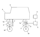
- the suspension vibration information obtained by the suspension vibration information estimation device E includes, for example, a damping force generated by a damper D interposed between the vehicle body B and the rear wheel Wr of the vehicle A, as shown in FIG. Although not, it is used in the control device C as information for determining the control force generated by the actuator.
- the vehicle A also includes a suspension spring Sp and a damper D interposed between the vehicle body B and the front wheel Wf and between the vehicle body B and the rear wheel Wr.
- the vehicle body B is elastically supported by the suspension spring Sp.
- the damper D includes a damping force adjusting unit F inside, and the control device C outputs a control command to the damping force adjusting unit F, whereby the damping force of the damper D is controlled.
- the device C is controlled according to the determined control force.
- the front-wheel unsprung vibration information detection unit 1 detects the front-wheel unsprung vibration information detection unit 1 with three acceleration sensors G1, G2, and G3 that are arranged on the vehicle body B so as not to line up on the same straight line. It is obtained from the acceleration in the vertical direction of the vehicle body B. If the vehicle body B is regarded as a rigid body and the acceleration in the vertical direction at any three locations not on the same straight line on the same horizontal plane of the vehicle body B is obtained, the vertical acceleration at an arbitrary position of the vehicle body B can be obtained. . Therefore, the front-wheel unsprung vibration information detection unit 1 includes an acceleration calculation unit 1a.
- the acceleration calculation unit 1a calculates the vertical acceleration directly above the front wheel Wf, and the obtained vertical acceleration directly above the front wheel. By integrating, the front wheel sprung speed Vbf is detected.
- the acceleration in the vertical direction of the vehicle body B may be detected by providing an acceleration sensor directly above the front wheel Wf of the vehicle body B instead of the acceleration sensors G1, G2, and G3.
- the rear wheel sprung vibration information detection unit 2 it is necessary for the rear wheel sprung vibration information detection unit 2 to detect the vertical acceleration immediately above the rear wheel Wr in the vehicle body B, and all four wheels of the front and rear wheels Wf, Wr of the four-wheeled vehicle are detected.
- the acceleration of the vehicle body B immediately above the vehicle is detected by the acceleration sensor, four acceleration sensors are required. Therefore, as described above, the acceleration is detected by the three acceleration sensors G1, G2, and G3. This is advantageous in that it can be done. This does not exclude the use of four acceleration sensors.
- the front-wheel unsprung vibration information detection unit 1 includes a stroke sensor H for detecting the suspension speed Vsf.
- the stroke sensor H may be any sensor that directly detects the relative displacement between the front wheel Wf and the vehicle body B, or may detect a state quantity that can be converted into a relative displacement between the front wheel Wf and the vehicle body B. Accordingly, the swing angle of the suspension arm that connects the front wheel Wf to the vehicle body B with respect to the vehicle body B may be detected.
- the damper D is connected to the vehicle body B via a mount (not shown) provided with anti-vibration rubber and the like, and is connected to the front wheel Wf via a bush (not shown).
- a mount not shown
- the influence of deformation of the mount and the bush is slight.
- the stroke sensor H may be integrally incorporated in the damper D interposed between the vehicle body B and the front wheel Wf.
- the front-wheel unsprung vibration information detection unit 1 detects the suspension speed Vsf by differentiating the vertical relative displacement between the vehicle body B and the front wheel Wf detected by the stroke sensor H.
- the front-wheel unsprung vibration information detection unit 1 includes an adding unit 1b, and the front-wheel unsprung velocity Vbf and the suspension speed Vsf obtained as described above are added by the adding unit 1b to obtain a front-wheel unsprung velocity Vwf.
- the front-wheel unsprung vibration information detection unit 1 calculates the acceleration directly above the front wheel Wf from the accelerations detected by the acceleration sensors G1, G2, and G3, integrates the acceleration, and integrates the acceleration.
- the speed Vbf is obtained.
- the suspension speed Vsf is obtained by differentiating the relative displacement between the vehicle body B and the front wheel Wf detected by the stroke sensor H.
- the vehicle body B always vibrates whenever the front wheel Wf vibrates, and a coupled vibration component is superimposed on the front wheel unsprung speed Vwf and the front wheel unsprung speed Vbf.
- the lever ratio of the suspension of the front wheel Wf is set.
- the suspension speed Vsf is obtained by subtracting the front wheel spring top speed Vbf from the front wheel spring bottom speed Vwf
- the value obtained by subtracting the front wheel spring top speed Vbf from the front wheel spring bottom speed Vwf is used as the front wheel side suspension speed Vsf as described above. An error that cannot be overlooked may occur between the suspension speed Vsf and the actual suspension speed due to the influence of the component vibration component and the lever ratio.
- the front wheel unsprung speed Vbf of the front wheel Wf is superposed with a component proportional to the front wheel unsprung speed Vbf due to the bend of the tire.
- a component proportional to the front-wheel unsprung speed Vwf is superimposed on.
- the front wheel unsprung speed Vwf is superposed with a speed component obtained by multiplying the front wheel sprung speed Vbf by a spring constant ratio obtained by dividing the spring constant of the suspension spring Sp by the spring constant of the tire. Therefore, when the suspension speed Vsf is calculated, if the speed component caused by the tire deflection is removed, the suspension speed Vsf can be matched with the actual suspension speed with higher accuracy.
- the lever ratio may be taken into consideration when removing the speed component due to the deflection of the tire.
- the above-mentioned spring constant ratio taking the lever ratio into account is considered as one gain, and the front wheel spring speed Vbf May be multiplied by this gain to calculate the speed component to be removed from the suspension speed Vsf.
- the suspension speed Vsr on the rear wheel side estimated by the suspension vibration information estimation unit 4 to be described later can be accurately matched to the actual suspension speed. .
- the front wheel unsprung vibration information detection unit 1 integrates the vertical acceleration directly above the front wheel Wf obtained by the acceleration calculation unit 1a.
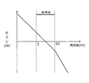
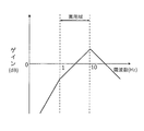
- a first integration low-pass filter 10 is provided. As shown in FIG. 2, the first integration low-pass filter 10 is used in a vehicle suspension practical range, generally in a frequency band of 1 Hz to several tens Hz. It has the characteristic that becomes large. By filtering the acceleration with the first integration low-pass filter 10, a value corresponding to the integral value of the acceleration can be obtained. Therefore, the front wheel sprung speed Vbf can be obtained by filtering the acceleration by the first integrating low-pass filter 10.
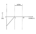
- the front wheel unsprung vibration information detecting unit 1 includes a first low frequency removing high pass filter 11, The sprung speed Vbf is filtered by the first low-frequency removing high-pass filter 11 to obtain the front-wheel sprung speed Vbf from which the integrated drift is removed by removing the low-frequency component.
- the cutoff frequency of the first low-frequency removing high-pass filter 11 is in a lower frequency range than the sprung resonance frequency, and consideration is given so that the sprung resonance frequency component is not removed from the front-wheel sprung speed Vbf.
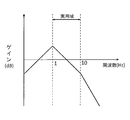
- the gain frequency characteristics of the first integration low-pass filter 10 and the first low-frequency removal high-pass filter 11 are combined, the characteristics shown in FIG. 4 are obtained.
- the acceleration may be filtered by the first low-frequency removing high-pass filter 11 before the first integration low-pass filter 10, and the processing order can be arbitrarily changed.
- the front-wheel unsprung vibration information detection unit 1 does not include the first integration low-pass filter 10 and the first low-frequency removal high-pass filter 11 separately, but instead includes the first integration low-pass filter 10 and the first low-pass filter 10.
- a single band-pass filter having the characteristics shown in FIG. 4 obtained by synthesizing the characteristics of the high-frequency filter 11 for removing the frequency may be provided, and processing may be performed by this band-pass filter.
- the front-wheel unsprung vibration information detection unit 1 includes a differentiation high-pass filter 12.
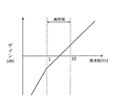
- the high-pass filter for differentiation 12 has a gain in response to an increase in frequency in a practical range of a vehicle suspension, generally in a frequency band of 1 Hz to several tens Hz, and in a frequency band below the practical range. It has the characteristic that the rise of When the relative displacement is filtered by the differentiation high-pass filter 12, a value corresponding to the differential value of the relative displacement is obtained. Therefore, the front-wheel unsprung vibration information detection unit 1 filters the relative displacement with the differential high-pass filter 12 to obtain the suspension speed Vsf.
- the front-wheel unsprung vibration information detection unit 1 includes a high-frequency removal low-pass filter 13, and the suspension speed Vsf is reduced to a high-frequency removal low-pass filter. Filtering is performed by the filter 13 to obtain a suspension speed Vsf from which high-frequency components are removed and differential noise is removed. As shown in FIG.
- the cutoff frequency of the high-frequency removal low-pass filter 13 is in a higher frequency range than the unsprung resonance frequency, and consideration is given so that the unsprung resonance frequency component is not removed from the suspension speed Vsf.
- the gain frequency characteristics of the differentiation high-pass filter 12 and the high-frequency removal low-pass filter 13 are synthesized, the characteristics shown in FIG. 7 are obtained.
- the relative displacement may be filtered by the high-frequency removing low-pass filter 13 before the differentiation high-pass filter 12, and the processing order can be arbitrarily changed.
- the front-wheel unsprung vibration information detection unit 1 does not include the differentiation high-pass filter 12 and the high-frequency removal low-pass filter 13 separately, but instead synthesizes the characteristics of the differentiation high-pass filter 12 and the high-frequency removal low-pass filter 13.
- a single bandpass filter having the characteristics shown in FIG. 7 may be provided, and processing may be performed by this bandpass filter.
- the acceleration immediately above the front wheel Wf is processed by the first integration low-pass filter 10 and the first low-frequency removal high-pass filter 11, and the relative displacement between the vehicle body B and the front wheel Wf is differentiated by the high-pass filter 12 for differentiation and the high-frequency removal. Since both pieces of information are processed by the high-pass filter and the low-pass filter, the degree of coincidence of the gain characteristics of both pieces of information after processing is increased in the practical range, and the front unsprung speed Vwf obtained from both pieces of information is processed. Improves accuracy.
- the first low-frequency removal high-pass filter 11 can be eliminated, and if the differential noise does not matter, the high-frequency removal low-pass filter 13 is eliminated. be able to.
- the integration of the acceleration immediately above the front wheel Wf may be obtained by integration calculation without using the first integration low-pass filter 10, and the differential of the relative displacement between the vehicle body B and the front wheel Wf is not using the differentiation high-pass filter 12. You may obtain
- the characteristics obtained by combining the characteristics of the first integration low-pass filter 10 and the first low-frequency removal high-pass filter 11 are matched with the characteristics obtained by combining the characteristics of the differentiation high-pass filter 12 and the high-frequency removal low-pass filter 13,
- the phase shift between them can be alleviated, and the sprung resonance frequency component can be effectively removed from the obtained front wheel unsprung speed Vwf to achieve accuracy.
- the front wheel unsprung speed Vwf can be detected well.
- the front wheel sprung speed Vbf and the suspension speed Vsf are added to obtain the front wheel sprung speed Vwf, but depending on the sign of the front wheel sprung speed Vbf and the suspension speed Vsf, the front wheel sprung speed In some cases, the front wheel unsprung speed Vwf may be obtained by subtracting the suspension speed Vsf from Vbf or by subtracting the front wheel sprung speed Vbf from the suspension speed Vsf.
- the front-wheel unsprung vibration information detection unit 1 continues to detect the front-wheel unsprung velocity Vwf every predetermined sampling period as described above, and records the obtained front-wheel unsprung velocity Vwf in the storage unit 5.
- the storage unit 5 is capable of storing data and continues to store the front-wheel unsprung speed Vwf. Further, the storage unit 5 accumulates until the data amount of the front-wheel unsprung speed Vwf reaches the storage capacity of the storage unit 5 or when a predetermined number of data is accumulated, the oldest data is sequentially updated. The front wheel unsprung speed Vwf is overwritten with the data, and the front wheel unsprung speed Vwf is stored while updating the data.
- the rear-wheel unsprung vibration information estimation unit 3 As shown in FIG. 1, has front wheels as front-wheel unsprung vibration information detected by the front-wheel unsprung vibration information detection unit 1. Based on the unsprung velocity Vwf, the longitudinal velocity Va of the vehicle A, and the wheel base length L of the vehicle A, the rear-wheel unsprung velocity Vwr is estimated as unsprung vibration information on the rear wheel Wr side of the vehicle A. It has become.
- the speed Va of the vehicle A is detected by a speed sensor 14 installed in the vehicle A and input to the rear-wheel unsprung vibration information estimation unit 3.
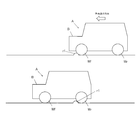
- the rear wheel unsprung vibration information estimation unit 3 estimates the rear wheel unsprung speed Vwr on the assumption that the rear wheel Wr in the vehicle A passes through the same road surface as the front wheel Wf in the vehicle A has passed. To do. As shown in FIG. 8, when the vehicle A is traveling, as shown in the upper diagram of FIG. 8, when the vehicle A travels straight after reaching the road surface r1 where the front wheel Wf is located, the front wheel Wf The rear wheel Wr provided on the same line along the front-rear direction of the vehicle A and behind the front wheel Wf is the same as the road surface on which the front wheel Wf passed several seconds later, as shown in the lower diagram of FIG. It will pass the road surface r1.
- the speed Va of the vehicle A is constant, if the wheel base length L that is the distance between the front wheel Wf and the rear wheel Wr of the vehicle A is known, the rear wheel Wr passes the road surface r1 after the front wheel Wf passes the road surface r1.
- the time to reach r1 can be obtained by calculating L / Va.
- the speed Va of the vehicle A changes after the front wheel Wf passes the road surface r1, the speed Va is monitored, and the integrated value of the speed Va after the front wheel Wf passes the road surface r1 becomes equal to the wheel base length L.
- the time is when the rear wheels Wr reach the same road surface r1.
- the rear-wheel unsprung vibration information estimation unit 3 determines from the speed Va of the vehicle A and the wheel base length L from the time when the front wheel Wf passes the road surface r1 to the time when the rear wheel Wr is considered to pass the road surface r1. Time T is obtained. Then, the rear-wheel unsprung vibration information estimation unit 3 determines that the rear-wheel Wr uses the front-wheel unsprung speed Vwf obtained at a time point before the time T when the rear-wheel Wr passes the road surface r1. It can be estimated that the rear wheel unsprung speed Vwr when passing through.
- the rear-wheel unsprung vibration information estimation unit 3 obtains a time T from the speed Va as the speed information in the longitudinal direction of the vehicle A and the wheelbase length L, and estimates the rear-wheel unsprung speed Vwr. Is read from the storage unit 5 as a rear wheel unsprung speed Vwr, which is obtained before time T.
- the storage unit 5 When storing the speed Vwf, the time when the front-wheel unsprung speed Vwf is detected may be associated with the front-wheel unsprung speed Vwf and stored.
- the rear-wheel unsprung vibration information estimation unit 3 linearly interpolates two front-wheel unsprung speeds Vwf obtained at the time closest to the time t and the time closest to the time t, and performs the time t
- the front-wheel unsprung speed Vwf obtained in the above is estimated, and the front-wheel unsprung speed Vwf may be set as the rear-wheel unsprung speed Vwr.
- the rear-wheel unsprung vibration information estimation unit 3 can also obtain the time T and set the front-wheel unsprung speed Vwf obtained at time t as the rear-wheel unsprung speed Vwr. Further, the rear-wheel unsprung vibration information estimating unit 3 associates the travel distance with the front-wheel unsprung speed Vwf in the storage unit 5 instead of obtaining the time T, so that the rear-wheel unsprung vibration information is estimated. Data of the front-wheel unsprung speed Vwf that should be the speed Vwr can also be extracted. For example, a method for extracting the data of the front unsprung speed Vwf without obtaining the time T will be described by taking the case where the number of data stored in the storage unit 5 is eight as an example.
- the front-wheel unsprung vibration information detection unit 1 detects the front-wheel unsprung velocity Vwf at a predetermined sampling cycle, and from # 1 to # 8 provided in the storage unit 5 each time the front-wheel unsprung velocity Vwf is detected.
- FIG. 9 shows a situation in which data in the memory which is the eight storage areas is updated. More specifically, when the front-wheel unsprung velocity Vwf obtained when the front-wheel unsprung velocity Vwf detected by the front-wheel unsprung vibration information detection unit 1 changes as shown in FIG. 10 is sequentially recorded in the storage unit 5. The data status is shown in FIG. FIG. 10 is a graph plotting data obtained by detecting the front unsprung speed Vwf 14 times when the vehicle A starts running and accelerates. In FIG.
- the value of the front unsprung speed Vwf is a virtual value that is deviated from the value obtained with the actual vehicle so that the data situation in FIG. 9 can be easily understood. Further, in FIG. 10, the detected data is plotted with black circles, and the estimated rear wheel unsprung speed Vwr is plotted with crosses.
- the front unsprung speed Vwf is recorded in the order detected in the memories # 1 to # 8 provided in the storage area in the storage unit 5 in association with the travel distance.
- the rear-wheel unsprung vibration information estimation unit 3 adds a counter value every time the recording is performed, and when the front-wheel unsprung speed Vwf and the travel distance are recorded in the storage unit 5, these are stored in a memory having the same number as the counter value. To store. In the case of this embodiment, since there are eight memories from # 1 to # 8, when the counter value is sequentially added from 1 to 9, the counter value is reset and rewritten to 1.
- the counter value is reset, and the next front-wheel unsprung speed Vwf and travel distance storage processing is performed. Since the counter value is 1 when performing the above, these pieces of information are recorded in the memory # 1.
- the front wheel unsprung speed Vwf detected for the first time is 0, as shown in FIG. 10, and therefore the value of the front wheel unsprung speed Vwf is recorded as 0 in the memory # 1 of the storage unit 5. Further, since the travel distance at the time when the value of the front wheel unsprung speed Vwf recorded in the memory # 1 is obtained is associated with the memory # 1, the travel distance is 0, and the travel distance of the memory # 1 is 0 is input. In order to easily understand the data situation of FIG. 9, the travel distance is also a value that is deviated from the value obtained with the actual vehicle as a virtual value, similar to the value of the front-wheel unsprung speed Vwf.
- the second front wheel unsprung speed Vwf is stored in the memory # 2. Since the value of the second front wheel unsprung speed Vwf is 1, the front wheel unsprung speed Vwf is recorded as 1 in the memory # 2. Further, since the travel distance at the time when the value of the front-wheel unsprung speed Vwf recorded in the memory # 2 is obtained is associated with the memory # 2, the travel distance recorded in the memory # 2 is 0. Therefore, 0 is input. On the other hand, when the first front wheel unsprung speed Vwf is detected as the travel distance value up to the previous time, the travel distance of the memory # 1 in which the value of the first front wheel unsprung speed Vwf has already been input is detected.
- the travel distance can be obtained by calculating Va / Ts from the sampling period Ts and the speed Va of the vehicle A.
- the third front wheel unsprung speed Vwf is stored in the memory # 3. Since the value of the third front wheel unsprung speed Vwf is 2, the front wheel unsprung speed Vwf is recorded as 2 in the memory # 3. Further, the travel distance associated with the front wheel unsprung speed Vwf in the memory # 3 is set to 0 as in the case of the travel distance associated with the first and second front wheel unsprung speeds Vwf. On the other hand, as the travel distance of the memory # 1 in which the value of the first front wheel unsprung speed Vwf has already been input, the second front wheel unsprung speed Vwf is detected at the travel distance updated last time.
- the travel distance of the data of the number for which the front wheel unsprung speed Vwf has already been recorded is updated to a value obtained by adding the travel distance this time to the travel distance recorded so far.
- the travel distance from the second time to the third time is 2, the current travel distance of 2 is added to the travel distance 1 of the memory # 1 recorded so far, The value of the travel distance in the memory # 1 is updated to 3.
- the front wheel unsprung speed Vwf is included in the travel distance of the number data in which the front wheel unsprung speed Vwf has been previously recorded.
- the travel distance from the time point when the latest front wheel unsprung speed Vwf is detected to the time point is detected is recorded.
- the travel distance in the memory # 2 is 2 by adding 2 of the current travel distance.
- the front wheel unsprung speed Vwf is recorded in the data having the next largest number after the data of the number in which the front wheel unsprung speed Vwf was updated last time.
- the front wheel unsprung speed Vwf is recorded in the memory # 8
- the next detected front wheel unsprung speed Vwf is overwritten and recorded in the memory # 1. That is, in this embodiment, eight pieces of data can be recorded in the storage unit 5, and if the number of detections of the front wheel unsprung speed Vwf exceeds 9, the front wheel unsprung obtained in the past from the 9th time. The value of the speed Vwf is updated to the newly obtained front wheel unsprung speed Vwf.
- the travel distance in the data of each number is the distance traveled by the vehicle A from the time when the front unsprung speed Vwf in the same data is detected to the present time.
- the unsprung speed Vwf can be obtained. Therefore, from the front wheel unsprung speed Vwf sequentially recorded in the storage unit 5, data having a traveling distance equal to the wheel base length L is selected, and the front wheel unsprung speed Vwf stored in this data is selected as the rear wheel unsprung speed. By setting the speed Vwr, the rear wheel unsprung speed Vwr can be estimated without obtaining the time T.
- the rear-wheel unsprung vibration information estimation unit 3 determines that the travel distance is closest to the wheelbase length L and the closest value. Is greater than the wheelbase length L, the data is smaller than the wheelbase length and has the second closest value to the wheelbase length. Select data with a value greater than the length and the second closest value to the wheelbase length. Then, the rear-wheel unsprung vibration information estimation unit 3 obtains the front-wheel unsprung speed Vwf from the two data having the closest value and the second-most value selected in this way, and the travel distance is calculated as the wheelbase length.
- the rear wheel unsprung speed Vwr may be estimated by linear interpolation as described above. In FIG.
- the rear wheel unsprung speed Vwr obtained in this way is plotted with a cross.
- the rear wheel Wr does not reach the road surface r1 through which the front wheel Wf has passed, and thus cannot be estimated.
- the rear wheel unsprung vibration information estimation unit 3 sets the value of the rear wheel unsprung speed Vwr to zero.
- the number of data recorded in the storage unit 5 is 8, but the number of data can be arbitrarily set.
- the rear-wheel unsprung vibration information estimation unit 3 estimates the rear-wheel unsprung speed Vwr using the vehicle speed information.
- the speed information in addition to the speed Va of the vehicle A, the travel distance obtained by dividing the speed Va by the sampling period Ts, information obtained by processing the speed Va such as the square value of the speed Va, and the speed such as the rotational speed of the wheel. Information capable of estimating Va is included.
- the rear-wheel unsprung vibration information estimation unit 3 includes a speed Va detected by the speed sensor 14, a current front-wheel unsprung speed Vwf detected by the front-wheel unsprung vibration information detection unit 1, and a current counter value. Is read (step S21).
- the rear-wheel unsprung vibration information estimation unit 3 reads the front-wheel unsprung velocity Vwf and the travel distance stored in each memory of the storage unit 5 (step S22), and obtains the travel distance to read each memory. The calculated travel distance is added to the travel distance, and the value is updated (step S23).
- the rear-wheel unsprung vibration information estimation unit 3 refers to the counter value and rewrites the travel distance of the memory having the number that matches the counter value to 0 to reset it to zero (step S24). Further, the number that matches the counter value The value of the front unsprung speed Vwf stored in the memory is updated to the current value of the front unsprung speed Vwf (step S25).
- the rear-wheel unsprung vibration information estimation unit 3 extracts the maximum value of the travel distance stored in each memory (step S26), and determines whether the maximum value of the travel distance is equal to or greater than the wheelbase length L. (Step S27). As a result of this determination, if the maximum value of the travel distance is less than the wheel base length L, the rear wheel Wr has not reached the road surface r1 through which the front wheel Wf has passed, so the rear-wheel unsprung vibration information estimation unit No. 3 cannot estimate the rear-wheel unsprung speed Vwr, so the rear-wheel unsprung speed Vwr is set to 0 (step S34), and the process proceeds to step S36. On the other hand, when the maximum value of the travel distance is greater than or equal to the wheelbase length L, the rear-wheel unsprung vibration information estimation unit 3 extracts the value closest to the wheelbase length L and the second closest value. (Step S28).
- the rear-wheel unsprung vibration information estimation unit 3 extracts the extracted travel distance. Are equal to each other (step S29). As a result, when the extracted traveling distances are equal, the vehicle is stopped. Therefore, the rear-wheel unsprung vibration information estimation unit 3 does not need to estimate the rear-wheel unsprung speed Vwr.
- the under-spring speed Vwr is set to 0 (step S35), and the process proceeds to step S36.
- the rear-wheel unsprung vibration information estimation unit 3 calculates the ratio necessary for the calculation of linear interpolation from the first value, the second value, and the wheelbase length L. Obtained (step S30).
- the rear wheel unsprung vibration information estimation unit 3 is stored in the same memory together with the value of the front wheel unsprung speed Vwf stored in the same memory together with the first value described above and the second value described above.
- the value of the front wheel unsprung speed Vwf is extracted (step S31), and the value of the two front wheel unsprung speeds Vwf extracted using the ratio obtained in step S30 is linearly interpolated to obtain the travel distance as the wheelbase length.
- a front wheel unsprung speed Vwf when L is reached is estimated (step S32).
- the rear wheel unsprung vibration information estimation unit 3 sets the rear wheel unsprung speed Vwr to the value of the front wheel unsprung speed Vwf obtained by linear interpolation (step S33).
- the rear-wheel unsprung vibration information estimation unit 3 stores the value of the front-wheel unsprung speed Vwf and the value of the travel distance updated in the processing so far in the corresponding memories (step S36).
- the rear wheel unsprung vibration information estimation unit 3 adds 1 to the counter value (step S37), and compares the count value with the number of data stored in all the memories (step S38). As a result of this comparison, if the counter value exceeds the number of stored data, the number of data of the front-wheel unsprung speed Vwf already stored in the storage unit 5 is the number of memories provided in the storage unit 5, so The counter value is reset to 1 (step S39) and the process proceeds to step S40 in order to overwrite and update the data of the front wheel unsprung speed Vwf recorded in (1) in order to overwrite and update from the memory in which the old data is recorded. .
- step S40 If the counter value is less than or equal to the number of stored data, there is a memory with a number that matches the counter value in the stored front wheel unsprung speed Vwf, and the memory with that number should be updated. Reset is not necessary, and the process proceeds to step S40.
- the rear-wheel unsprung vibration information estimation unit 3 outputs the rear-wheel unsprung velocity Vwr estimated by executing the above-described processing procedure to the suspension vibration information estimation unit 4 (step S40).
- the rear-wheel unsprung vibration information estimation unit 3 repeatedly performs the above-described series of processes, and continues to estimate the rear-wheel unsprung speed Vwr.
- the rear wheel spring vibration information detection unit 2 is rear as rear wheel spring vibration information which is spring vibration information on the rear wheel Wr side, as shown in FIG.
- the rear wheel sprung speed Vbr which is the speed in the vertical direction of the vehicle body B immediately above the wheel Wr, is detected.
- the rear wheel sprung vibration information detection unit 2 includes an acceleration calculation unit 2a in the same manner as the front wheel sprung speed Vbf described above in detecting the rear wheel sprung speed Vbr.
- the acceleration calculation unit 2a includes three acceleration sensors. The vertical acceleration directly above the rear wheel Wr is obtained from the vertical acceleration of the vehicle body B detected by G1, G2, and G3. Subsequently, the rear wheel sprung vibration information detecting unit 2 detects the rear wheel sprung speed Vbr by integrating the acceleration.
- the rear wheel sprung vibration information detecting unit 2 includes a second integrating low-pass filter 20.
- the second integration low-pass filter 20 can filter the acceleration to obtain a value corresponding to the integrated value of the acceleration. Therefore, the second integration low-pass filter 20 can obtain the rear wheel sprung speed Vbr by filtering the acceleration.
- the rear wheel sprung vibration information detecting unit 2 includes a second low frequency removing high pass filter 21. .
- the rear wheel sprung vibration information detection unit 2 filters the rear wheel sprung speed Vbr with the second low-frequency removing high-pass filter 21, thereby removing the low-frequency component and removing the integrated drift.
- the sprung speed Vbr can be obtained.
- the cutoff frequency of the second low-frequency removing high-pass filter 21 is in a lower frequency range than the sprung resonance frequency, and consideration is given so that the sprung resonance frequency component is not removed from the rear-wheel sprung speed Vbr.
- the acceleration may be filtered by the second low-frequency removing high-pass filter 21 before the second integrating low-pass filter 20, and the processing order can be arbitrarily changed.
- the rear wheel sprung vibration information detection unit 2 does not include the second integration low-pass filter 20 and the second low-frequency removing high-pass filter 21 separately, but instead includes the second integration low-pass filter 20 and the second low-pass filter 20.
- a single band-pass filter having characteristics obtained by synthesizing the characteristics of the low-frequency removal high-pass filter 21 may be provided, and processing may be performed by this band-pass filter.
- the rear wheel sprung speed Vbr obtained in this way is used to estimate the suspension speed Vsr on the rear wheel side of the suspension vibration information estimation unit 4.
- the suspension vibration information estimation unit 4 obtains the rear wheel suspension speed Vsr by subtracting the rear wheel sprung speed Vbr from the rear wheel unsprung speed Vwr.
- the degree of coincidence between the phase characteristics and the gain characteristics of the upper speed Vbr and the rear wheel unsprung speed Vwr may be increased.
- the acceleration immediately above the rear wheel Wr is processed by the second integration low-pass filter 20 and the second low-frequency removing high-pass filter 21 to obtain the rear wheel sprung speed Vbr.
- the integration low-pass filter 10 the first low-frequency removal high-pass filter 11, the differentiation high-pass filter 12, and the high-frequency removal low-pass filter 13, the degree of coincidence of the gain characteristics of both information can be increased in a practical range.
- the accuracy of the suspension speed Vsr on the rear wheel side determined from the information is improved.
- the second low-frequency removal high-pass filter 21 can be eliminated.
- the integral of the acceleration immediately above the rear wheel Wr may be obtained by an integral calculation without using the second integration low-pass filter 20.
- a characteristic obtained by synthesizing the characteristics of the first integration low-pass filter 10 and the first low-frequency removal high-pass filter 11 a characteristic obtained by synthesizing the characteristics of the differentiation high-pass filter 12 and the high-frequency removal low-pass filter 13, and a second integration
- the characteristics obtained by synthesizing the characteristics of the low-pass filter 20 and the second low-frequency removing high-pass filter 21 are the same, not only the gain characteristics of the rear wheel spring upper speed Vbr and the rear wheel unsprung speed Vwr match, The phase characteristic deviation can be reduced, and the degree of coincidence between the obtained suspension speed Vsr and the actual suspension speed can be increased.
- the suspension vibration information estimation unit 4 is based on the rear wheel unsprung speed Vwr as the estimated rear wheel unsprung vibration information and the rear wheel unsprung speed Vbr as the rear wheel unsprung vibration information.
- the rear wheel spring speed Vbr is subtracted from the wheel spring lower speed Vwr to determine the rear wheel suspension speed Vsr as suspension vibration information on the rear wheel Wr side in the vehicle A.
- the suspension vibration information estimation device E of the present invention obtains the suspension vibration information on the rear wheel Wr side in the vehicle A based on the rear-wheel unsprung vibration information and the rear-wheel sprung vibration information.
- the suspension vibration information is estimated in consideration of the vibration state of the vehicle body B on the side. Therefore, the suspension vibration information estimation device E of the present invention can accurately estimate the suspension vibration information on the rear wheel Wr side.
- the vehicle body B also vibrates, and a coupled vibration component is superimposed on the rear wheel unsprung speed Vwr and the rear wheel unsprung speed Vbr. Further, the lever ratio of the rear wheel Wr suspension is set. If the value obtained by subtracting the rear wheel spring upper speed Vbr from the rear wheel unsprung speed Vwr is used as the rear wheel suspension speed Vsr as it is, the suspension speed Vsr and the actual suspension speed are affected by the above-described coupled vibration component and lever ratio. When an error that cannot be overlooked occurs, as shown in FIG. 1, a compensation gain multiplication unit 6 is provided to multiply the suspension gain Vsr by the compensation gain so as to remove the influence of the coupled vibration component and the lever ratio.
- the suspension speed Vsr can be accurately matched with the actual suspension speed.
- the compensation gain multiplication unit 6 may be omitted.
- the suspension speed Vsr is obtained by subtracting the rear wheel spring upper speed Vbr from the rear wheel spring lower speed Vwr, but depending on how the signs of the rear wheel spring upper speed Vbr and the suspension speed Vsr are taken,
- the suspension speed Vsr may be obtained by subtracting the rear wheel unsprung speed Vwr from the upper speed Vbr or adding the rear wheel unsprung speed Vbr and the rear wheel unsprung speed Vwr.
- a phase compensation filter 7 is provided as shown in FIG.
- the phase can be matched to the actual suspension speed phase. By matching the phases in this way, a more accurate suspension speed Vsf can be obtained.
- the suspension vibration information estimation device E estimates the suspension speed Vsr on the rear wheel Wr side on the assumption that the rear wheel Wr passes through the same road surface r1 as the road surface r1 through which the front wheel Wf has passed.
- the reliability that the estimated suspension speed Vsr matches the actual suspension speed is low.
- the suspension vibration information estimation device E estimates the control device C that controls the damper D that can adjust the damping force interposed between the vehicle body B and the rear wheel Wr in the vehicle A.
- the control device C controls the damping force of the damper D on the basis of the suspension speed Vsr with low reliability.
- the suspension speed Vsr is equivalent to the damper speed, which is the expansion / contraction speed of the damper D interposed between the rear wheel Wr and the vehicle body B.
- the damper speed is obtained. Will be. Since the damper D exhibits a damping force with respect to the damper speed, the information suitable for the control device C that controls the damping force of the damper D is obtained by obtaining the damper speed by the suspension vibration information estimation device E in this way. Can be provided.
- the suspension vibration information estimation apparatus E of the present embodiment as shown in FIG. 1, the reliability that the suspension speed Vsr obtained by the suspension vibration information estimation unit 4 matches the actual suspension speed on the rear wheel Wr side is obtained.
- a determination unit 8 for determination is provided.
- the determination unit 8 may obtain the reliability as a numerical value, or can determine the presence or absence of the reliability. In this embodiment, as shown in FIG. 1, the determination unit 8 obtains the reliability as a numerical value and outputs the reliability to the reliability gain multiplication unit 9.
- the reliability gain multiplication unit 9 obtains a reliability gain P according to the reliability, and multiplies the reliability gain P by the suspension speed Vsr obtained by the suspension vibration information estimation unit 4. Therefore, the suspension vibration information estimation device E of the present embodiment outputs the suspension speed Vsr multiplied by the reliability gain P as the final suspension speed Vsrl.
- the reliability of the suspension speed Vsr becomes low.
- the possibility that the rear wheel Wr does not pass through the road surface r1 through which the front wheel Wf has passed increases (1) when the steering angle of the steering wheel is large, (2) when counter-steering is performed while the vehicle is turning, (3 ) When traveling with significant understeer (4) When traveling neutrally but drifting with four wheels sliding, (5) When the vehicle is moving backward.
- the steering angle of the steering wheel of the vehicle A may be monitored.
- the lateral acceleration actually acting on the vehicle body B, the speed Va and the steering wheel The reliability can be determined from the amount of deviation and the degree of deviation from the lateral acceleration of the vehicle body B estimated from the steering angle. It is possible to determine the reliability from the value of the stability factor by obtaining the value referred to as the stability factor from the lateral acceleration actually acting on the vehicle body B, the speed Va, and the steering angle ⁇ of the steering wheel. .
- the speed Va of the vehicle A may be monitored.
- the determination method in the determination unit 8 for each case will be described in more detail.
- the reliability is lowered when the steering angle is large.
- the radius of the trajectory of the front wheel Wf and the rear wheel Wr aligned in the front-rear direction of the vehicle A differs depending on the inner wheel difference or the outer wheel difference. Also grows. Further, as the steering angle of the front wheel Wf of the vehicle A increases, the inner wheel difference or the outer wheel difference increases. From the above, as shown in FIG. 1, the steering angle ⁇ from the neutral position of the steering wheel Sw of the vehicle A is detected by the steering angle sensor 30, and the determination unit 8 determines the reliability of the suspension speed Vsr based on the steering angle ⁇ . Find it.
- a threshold value ⁇ a is provided for the absolute value of the steering angle ⁇ , and the reliability can be gradually lowered when the threshold value ⁇ a is exceeded, and the absolute value of the steering angle ⁇ is set to the threshold value ⁇ a. If it exceeds, the reliability may be set to zero.
- the threshold value ⁇ a may be set to a steering angle that ensures that the rear wheel Wr does not pass through the road surface r1 that has passed through the front wheel Wf due to an inner wheel difference or an outer wheel difference.
- the specific setting of the threshold value ⁇ a can be obtained from the wheelbase length L and the tread length.
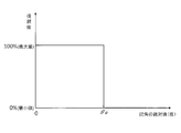
- the determination unit 8 sets the reliability to the minimum value, for example, 0, and conversely, if the absolute value of the steering angle ⁇ is within the range of the threshold ⁇ a, the determination unit 8 sets the reliability to the maximum value set in advance. What is necessary is just to output to the gain multiplication part 9. That is, the value that can be taken as the reliability is the minimum value or the maximum value as shown in FIG. The minimum value and the maximum value of the reliability can be arbitrarily set. For example, when expressed as a percentage, as shown in FIG. 14, if the minimum value is 0% and the maximum value is 100%, Good.
- the determination unit 8 sets the reliability to the minimum value, and conversely, for example, if the absolute value of the steering angle ⁇ is within the range of the threshold ⁇ a, the determination unit 8 determines the reliability according to the absolute value of the steering angle ⁇ . It is also possible to change between the minimum value and the maximum value. That is, it is possible to change the reliability value according to the magnitude of the steering angle ⁇ . As shown in FIG.
- the reliability is set to the maximum value within the rudder angle range where the absolute value of the rudder angle ⁇ seems to surely pass the road surface r1 through which the front wheel Wf has passed. It is also possible to change the reliability from the maximum value to the minimum value within the range from the steering angle ⁇ b to the threshold value beyond the range.
- the determination unit 8 determines the reliability using the steering angle ⁇ of the handle Sw. However, the determination unit 8 may determine using the steering angle information that can specify the steering angle ⁇ . In addition to the steering angle ⁇ itself, the actual steering angle of the steered wheels and information obtained by processing the steering angle ⁇ are also included.
- the vehicle A does not turn according to the steering angle ⁇ , but the vehicle A is skidding.
- the vehicle body B slides in the lateral direction, it cannot be expected that the rear wheel Wr will pass through the road surface r1 through which the front wheel Wf has passed. Therefore, when it determines with it being such a condition, the determination part 8 will reduce reliability.
- the lateral acceleration acting on the vehicle body B while the vehicle A is turning is mainly composed of centrifugal acceleration acting on the vehicle body B as the vehicle A turns. Assuming that the front wheel Wf and the rear wheel Wr are not skid sideways, the turning radius of the vehicle A is determined by the steering angle ⁇ , and the turning speed becomes the speed Va detected by the speed sensor 14, so the steering angle ⁇ and the speed Va Can be estimated, the lateral acceleration acting on the vehicle body B while the vehicle A is turning can be estimated.
- the steering angle of the front wheel Wf that is the actual steered wheel is ⁇ w with respect to the steering angle ⁇ of the steering wheel Sw
- the steering angle ⁇ and the steering angle ⁇ w are in a proportional relationship
- the turning radius of the vehicle A can be obtained from the angle ⁇ w.
- the determination unit 8 obtains the steering angle ⁇ and the speed Va from the steering angle sensor 30 and the speed sensor 14 and estimates the lateral acceleration acting on the vehicle body B as described above. Note that the determination unit 8 only needs to know the steering angle ⁇ w of the steered wheel, so that the reliability may be determined by detecting the actual steering angle ⁇ w of the front wheel Wf instead of the steering angle ⁇ of the steering wheel Sw. If the facing wheel is the rear wheel Wr, the reliability may be determined by detecting the actual steering angle of the rear wheel Wr.
- the vehicle A acts on the vehicle body B because the vehicle A does not turn according to the steering angle ⁇ but is in a skidding state.
- the actual lateral acceleration ⁇ can be obtained by assuming that the vehicle body B is a rigid body from the accelerations detected by the acceleration sensors G1, G2, and G3.
- the determination unit 8 detects the lateral acceleration actually acting on the vehicle body B from the accelerations detected by the acceleration sensors G1, G2, and G3.
- the lateral acceleration may be detected by providing an acceleration sensor separately from the acceleration sensors G1, G2, and G3.
- the determination unit 8 obtains the reliability from the deviation between the actual acceleration ⁇ and the estimated acceleration. Specifically, the determination unit 8 examines the ratio of the deviation between the acceleration ⁇ and the estimated acceleration to the acceleration ⁇ , obtains the degree of coincidence between the acceleration ⁇ and the estimated acceleration, and uses this as the reliability, It is possible to map the relationship with the reliability and obtain the reliability from the deviation.
- the acceleration ⁇ Va 2 ⁇ ⁇ w / L, and Va 2 ⁇ ⁇ w / L is nothing but centrifugal acceleration, and it can be seen that the vehicle A is not skidding.
- the stability factor Sf is a positive value, the vehicle A is in an understeer state.
- the stability factor Sf is a negative value, the vehicle A is in an oversteer state. Therefore, it is possible to determine whether or not the vehicle A is in a skidding state by obtaining the value of the stability factor Sf.
- the determination unit 8 determines the stability factor Sf
- the absolute value of the stability factor Sf is used as a parameter, the absolute value and the reliability are mapped, the reliability can be obtained numerically from the absolute value of the stability factor Sf, and a threshold is provided. It is also possible to determine the presence or absence of reliability using a threshold value.
- the vehicle A does not turn according to the steering angle ⁇ of the handle Sw, but the vehicle A is skidding, and the actual yaw rate of the vehicle A and the steering angle of the handle Sw are It deviates from the yaw rate estimated from ⁇ . Therefore, instead of obtaining the reliability from the difference between the actual lateral acceleration ⁇ acting on the vehicle body B and the estimated lateral acceleration, the actual yaw rate of the vehicle A and the steering angle ⁇ of the handle Sw The reliability can be obtained from the deviation from the yaw rate estimated from.
- the actual yaw rate of the vehicle A may be detected by providing the vehicle A with a yaw rate sensor.
- the yaw rate is obtained by dividing the tangential speed of the vehicle A that is turning by the turning radius.
- the turning radius is obtained from the wheelbase length L and the steering angle ⁇ as described above, and the tangential speed is the speed Va. Therefore, the yaw rate can be estimated using the speed Va and the steering angle ⁇ .
- the vehicle A When the deviation between the actual yaw rate of the vehicle A and the yaw rate estimated from the steering angle ⁇ of the steering wheel Sw is large, the vehicle A is in a skidding state. Therefore, the reliability increases as the deviation increases. Therefore, the reliability can be obtained if the deviation is calculated.
- the speed Va is monitored, and if it is determined that the vehicle A is moving backward from the value of the detected speed Va, the reliability may be set to the minimum value.
- the reverse of the vehicle can also be determined by monitoring the gear position of the transmission.
- the front-wheel unsprung speed Vwf obtained before the time obtained by monitoring the speed change as described above is used as the rear-wheel spring of the rear-wheel Wr. It is likely that the lower speed Vwr can be estimated. For example, assuming that the speed Va has doubled since the front wheel Wf has passed the road surface r1, and estimating the rear wheel unsprung speed Vwr as described above, the front wheel spring of the front wheel Wf is as shown in FIG.
- the rear-wheel unsprung speed Vwr obtained by estimation with respect to the vibration waveform when the lower speed Vwf is obtained is compressed by a half of the vibration cycle.
- the front wheel Wf and the rear wheel Wr which are unsprung members, are a spring mass system of a suspension spring interposed between the tire and the vehicle body B, and the front wheel Wf and the rear wheel Wr basically have a specific resonance. It will vibrate at a frequency.
- the vibration frequency of the rear wheel unsprung speed Vwr estimated by doubling the speed Va is twice the vibration frequency of the front wheel unsprung speed Vwf. Since the resonance frequency of Wr does not change, the estimated rear wheel unsprung speed Vwr deviates from the actual rear wheel unsprung speed Vwr. As the amount of change in the speed Va of the vehicle A after the front wheel Wf passes the road surface r1, the difference between the two becomes more significant, and the reliability decreases.
- the determination unit 8 reduces the reliability according to the speed change between the speed when the front wheel Wf passes the road surface r1 and the speed when the rear wheel Wr passes the road surface r1.
- the speed Va when the front wheel Wf passes the road surface r1 the higher the speed Va, the longer the front wheel Wf passes the road surface r1 until the rear wheel Wr passes the road surface r1.
- Time is shortened.
- the time for the rear wheel Wr to pass the road surface r1 after the front wheel Wf passes the road surface r1 is the time for acceleration (acceleration in the longitudinal direction of the vehicle A) during acceleration or deceleration to act on the vehicle A. If the acceleration is constant, the shorter this time, the smaller the speed change amount.
- the absolute value of the acceleration acting in the front-rear direction of the vehicle A is larger, the amount of change in speed is increased and the reliability is lowered.
- the determination unit 8 determines the reliability based on the speed Va and the degree of increase / decrease of the vehicle A in the front-rear direction.
- the vertical axis represents the speed Va of the vehicle A and the horizontal axis represents the vehicle
- the speed Va when the front wheel Wf and the rear wheel Wr pass the same road surface by taking the travel distance A (travel distance after passing through a point where the front wheel or the rear wheel passes) is as shown in FIG. Transition.
- 17A shows the speed change of the vehicle A when the front wheel Wf passes the road surface
- the broken line in the figure shows the vehicle when the rear wheel Wr passes through the same road surface as the front wheel Wf.
- a speed change of A is shown.
- a speed ratio obtained by dividing the speed of the vehicle A when the rear wheel Wr passes the same road surface by the speed of the vehicle A when the front wheel Wf passes the road surface on the vertical axis is taken.
- the speed ratio changes as shown in FIG. Focusing on the point at which the speed ratio is 90%, when the speed Va when the front wheel Wf passes the road surface r1 is lower than 45 km / h, the speed ratio falls below 90%, and the front wheel Wf and the rear wheel Wr are on the same road surface.
- the speed change amount when passing through r1 increases.
- the vertical axis represents the speed Va of the vehicle A
- the horizontal axis represents the travel distance of the vehicle A (a point where the front wheel or rear wheel is located).
- the speed ratio ⁇ is obtained by dividing the speed of the vehicle A when the rear wheel Wr passes by the speed of the vehicle A when the front wheel Wf passes through a certain road surface, and the front wheel Wf passes through a road surface during acceleration.
- the speed ratio ⁇ obtained by dividing the speed of the vehicle A when the rear wheel Wr passes by the speed A of the vehicle A when the rear wheel Wr passes the estimated rear wheel spring in a situation where the speed ratio ⁇ or the speed ratio ⁇ is 90%.
- the vibration cycle of the lower speed Vwr is 0.9 times during deceleration and about 1.1 times during acceleration relative to the actual vibration cycle of the rear wheel unsprung speed Vwr.
- the degree of reliability is set to 0 when the speed ratio is 90% or less.
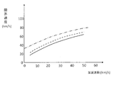
- FIG. 19 shows the relationship between the limit speed Vlim and the acceleration / deceleration rate at which the speed ratios ⁇ and ⁇ are 90%.
- the limit speed increases as the acceleration / deceleration rate increases, and this tendency is the same during deceleration and acceleration.
- the values at which the speed ratio ⁇ , ⁇ is 93% are plotted in the graph, and the average speed from the speed at which the speed ratio ⁇ is 93% and the speed at which ⁇ is 93% to the speed ratio ⁇ , ⁇ 90%. In this range, the reliability is gradually lowered.
- FIG. 19 shows the relationship between the limit speed Vlim and the acceleration / deceleration rate at which the speed ratios ⁇ and ⁇ are 90%.
- the solid line is the speed at which the speed ratio ⁇ is 90% during acceleration
- the broken line is the speed at which the speed ratio ⁇ is 90% during deceleration
- the alternate long and short dash line is the speed at which the speed ratio ⁇ is 93% and ⁇ is 93 It shows the average speed of the speed that is%.
- this alternate long and short dash line is expressed as a boundary velocity line.
- the reliability when the reliability is expressed as a percentage, the reliability when the relationship between the speed and the acceleration / deceleration rate is on this boundary speed line is 100%, and the reliability when the speed ratio ⁇ , ⁇ is 90% is 0%. In the section where the speed ratios ⁇ and ⁇ are 90% from the boundary speed line, the reliability changes linearly.
- the determination unit 8 maps and holds the relationship between the limit speed as shown in FIG. 19, the acceleration / deceleration rate, the speed at which the speed ratio ⁇ is 93%, and the average speed at which ⁇ is 93%.
- the reliability may be obtained as a value from the speed Va and the acceleration / deceleration rate.
- the vertical value is the square value of the limit speed, as shown in FIG. 20, the square value of the limit speed has a characteristic that is approximately proportional to the acceleration / deceleration rate.
- the acceleration / deceleration rate is determined by calculating the speed at which the speed ratio ⁇ is 93% and the speed at which ⁇ is 93% and the speed at which the speed ratios ⁇ and ⁇ are 90%. The reliability may be obtained by comparing the obtained speed with the current speed as a threshold value. Also in FIG.
- the solid line is the speed at which the speed ratio ⁇ is 90% during acceleration
- the broken line is the speed at which the speed ratio ⁇ is 90% during deceleration
- the alternate long and short dash line is the speed at which the speed ratio ⁇ is 93% and ⁇ An average speed of 93% is drawn.
- the speed at which the speed ratio ⁇ , ⁇ is 90% is set as a threshold value, and the reliability is 0%.
- the threshold value is set at a speed ratio ⁇ , ⁇ other than 90% depending on the specification of the vehicle. Can be set. Since the wheel base length L affects the time from the passage of the road surface r1 of the front wheel Wf to the arrival of the road surface r1 of the rear wheel Wr, the map and calculation held by the determination unit 8 taking the wheel base length L into consideration An expression should be set.
- the determination unit 8 has the reliability obtained from the steering angle ⁇ of the handle Sw of the case (1), and Obtained by judging whether the vehicle A in the case (2) to the case (4) is sliding or not and judging whether the vehicle A in the case (5) is moving backward. From the reliability, the reliability obtained from the speed Va and the acceleration / deceleration rate of case (6), the reliability having the smallest value is selected (low selected) and output to the reliability gain multiplication unit 9.
- the reliability gain multiplication unit 9 obtains a reliability gain using a map or an arithmetic expression for obtaining the reliability gain from the reliability, and multiplies the suspension speed Vsr obtained by the suspension vibration information estimation unit 4 by the reliability gain for output. To do. As shown in FIG. 12, when the phase compensation filter 7 is provided, the output of the phase compensation filter 7 may be multiplied by the reliability gain, or the suspension vibration information estimation unit 4 may be provided in the previous stage of the phase compensation filter 7. The obtained suspension speed Vsr may be multiplied by a reliability gain.
- the determination unit 8 calculates four reliability levels, but only a part of the four reliability levels is calculated. It is also possible. However, by obtaining all the above-described reliability and performing low-selection, the situation where the rear wheel Wr cannot pass through the same road surface r1 as the front wheel Wf can be covered in many ways, so that a highly reliable suspension speed Vsr can be obtained. it can.
- the suspension speed Vsr on the rear wheel side can be obtained without providing the determination unit 8, but the reliability of the rear-wheel unsprung speed Vwr estimated by the determination unit 8 is obtained, and the reliability is multiplied by the reliability gain multiplication unit 9.
- the suspension speed Vsr as the suspension vibration information is obtained, the suspension speed Vsr having a higher degree of coincidence can be obtained by the actual suspension speed.
- the determination unit 8 uses the speed Va in the front-rear direction of the vehicle A when performing the determination from the case (2) to the case (6), but can determine using the vehicle speed information.
- the speed information is a concept including information obtained by processing the speed Va such as the square value of the speed Va of the vehicle A and information capable of estimating the speed Va such as the rotation speed of the wheel.
- the reliability gain multiplication unit 9 obtains the reliability gain by associating the reliability gain with the reliability value expressed as a percentage.
- the reliability gain is set to continuously change from 1 to 0 as shown in the map of FIG. 21 in response to the reliability changing from 100% to 0% of the maximum value.
- the value of the reliability gain can be changed stepwise from 1 to 0 with a reliable value. If the former, since the suspension speed Vsr gradually approaches 0 as the reliability decreases, an effect that the signal of the suspension speed Vsr input to the control device C fades out can be obtained. A sudden change in value can be avoided.
- the control device C obtains the target damping force of the damper D also from vibration information other than the suspension speed Vsr, and the high selection uses the maximum value among the plurality of target damping forces as the final target damping force.
- the determination unit 8 determines the presence or absence of reliability
- the determination unit 8 outputs a value of 1 or 0, and the reliability In the gain multiplication unit 9, the output of the determination unit 8 may be directly multiplied by the suspension speed Vsr.
- the determination unit 8 obtains the reliability. However, apart from this, the rear wheel unsprung speed Vwr may not be accurately estimated due to the storage capacity of the storage unit 5.
- the front unsprung velocity Vwf is periodically detected at a predetermined sampling period Ts as described above. It takes time to mean that the number of data of the front unsprung speed Vwf detected from when the front wheel Wf passes the road surface r1 to when the rear wheel Wr reaches the road surface r1 increases.
- the number of data of the front-wheel unsprung speed Vwf sampled from when the front wheel Wf passes the road surface r1 until the rear wheel Wr reaches the road surface r1 can be stored in the storage unit 5.
- the value of the front wheel unsprung speed Vwf to be referred to when the rear wheel Wr reaches the road surface r1 passes through a road surface different from the road surface r1. Therefore, the rear wheel unsprung speed Vwr cannot be estimated accurately.
- an estimated stop determination unit 15 is provided.
- the estimated stop determination unit 15 provides a speed threshold value, and when the speed Va is lower than the speed threshold value, the reliability gain multiplication unit 9 multiplies the suspension speed Vsr as suspension vibration information by 0 and the speed Va becomes a speed. When it is equal to or higher than the threshold value, the suspension speed Vsr is multiplied by 1 and output. In the case of this embodiment, this output is the final suspension speed Vsr obtained by the suspension vibration information estimation device E.
- the reliability in the determination unit 8 it has been described that the reliability is lowered when the steering angle ⁇ of the handle Sw corresponding to the case (1) is large. Is increased when the speed Va of the vehicle A is low.
- the determination unit 8 may make only the determination by the estimated stop determination unit 15 instead of the reliability determination by the steering angle ⁇ . Good. Further, the speed threshold value Vref can be determined using the number of data N, the wheel base length L, and the sampling period Ts. The estimated stop determination unit 15 may be omitted if there is a large amount of data that can be stored in the storage unit 5 and it does not matter even if the speed Va is low.
- each part of the suspension vibration information estimation device E has been described.
- a process for obtaining suspension vibration information by the suspension vibration information estimation device E will be described. This process is a process for obtaining the suspension speeds of the left and right rear wheels Wr disposed behind the front wheels Wf from the front-wheel unsprung vibration information of the left and right front wheels Wf of the four-wheel vehicle.
- the suspension vibration information estimation device E includes a speed Va detected by the speed sensor 14, an acceleration detected by the acceleration sensors G1, G2, and G3, a steering angle ⁇ detected by the steering angle sensor 30, and a stroke sensor H.
- a speed Va detected by the speed sensor 14 an acceleration detected by the acceleration sensors G1, G2, and G3, a steering angle ⁇ detected by the steering angle sensor 30, and a stroke sensor H.
- Each detection data of relative displacement between the vehicle body B and the front wheel Wf detected by is read (step S1).
- the suspension vibration information estimation device E calculates sprung speeds Vbf and Vbr as sprung vibration information before and after the vehicle A from the accelerations detected by the acceleration sensors G1, G2, and G3 (step S2).
- the front wheel sprung speed Vbf is filtered by the first integration low-pass filter 10 and the first low-frequency removing high-pass filter 11, and the rear wheel sprung speed Vbr is converted to the second integration low-pass filter.
- a filtering process is performed by the filter 20 and the second low-frequency removing high-pass filter 21.
- the suspension vibration information estimation device E obtains a front wheel unsprung speed Vwf as front wheel unsprung vibration information (step S3). Specifically, the suspension vibration information estimation device E obtains the suspension speed Vsf by differentiating the vertical relative displacement between the vehicle body B and the front wheel Wf detected by the stroke sensor H. Further, the suspension vibration information estimation device E adds the front wheel sprung speed Vbf and the suspension speed Vsf obtained in step S2 to obtain the front wheel unsprung speed Vwf for the two front wheels Wf on the left and right of the vehicle A, respectively. In the process of step S3, the suspension speed Vsf is also filtered by the high-pass filter 12 for differentiation and the low-pass filter 13 for high frequency removal.
- the suspension vibration information estimation device E predicts that the rear wheel Wr reaches the road surface r1 through which the front wheel Wf has passed, and the front wheel Wf in front of each of the left and right rear wheels Wr of the vehicle A passes through the road surface r1. It is estimated that the front wheel unsprung speed Vwf is the rear wheel unsprung speed Vwr (step S4).
- This estimation process corresponds to the process from step S21 to step S40 described above.
- a time T required for the rear wheel Wr to reach the road surface r1 through which the front wheel Wf has passed is obtained from the speed Va and the wheel base length L, and the time T is increased.
- the front wheel unsprung speed Vwf stored in the storage unit 5 may be set to the rear wheel unsprung speed Vwr.
- the suspension vibration information estimation device E corresponds to the left and right rear wheels Wr from the rear wheel unsprung speed Vwr obtained in step S4 and corresponds to the left and right rear wheels Wr.
- the suspension speed Vsr of the left and right rear wheels Wr is obtained by subtracting the speed Vbr (step S5).
- step S5 if there is a case where an error that cannot be overlooked may occur between the suspension speed Vsr obtained by the influence of the above-described coupled vibration component and lever ratio and the actual suspension speed, compensation by the compensation gain multiplier 6 is performed. A process of multiplying the gain by the suspension speed Vsr is also performed.
- the suspension speed Vsr is filtered by the phase compensation filter 7 so that the phase matches the phase of the actual suspension speed. Also do.
- the processing of the compensation gain multiplication unit 6 and the processing of the phase compensation filter 7 can be omitted if unnecessary.
- the suspension vibration information estimation device E obtains the reliability of the obtained suspension speed Vsr, and multiplies the suspension speed Vsr by a reliability gain corresponding to the reliability to correct the suspension speed Vsr (step S6).
- This process is a process performed by the determination unit 8 described above.
- the suspension vibration information estimation device E determines whether the speed Va is equal to or higher than the speed threshold with respect to the suspension speed Vsr processed in step S6. If the speed Va is lower than the speed threshold, the suspension vibration information estimation apparatus E changes to the suspension speed Vsr. When 0 is multiplied and the speed Va is equal to or higher than the speed threshold, the suspension speed Vsr is multiplied by 1 and output (steps S7 to S10). Note that the suspension speed Vsr may be set to 0 when the speed Va is lower than the speed threshold, and the suspension speed Vsr may be output as it is when the speed Va is equal to or higher than the speed threshold. The suspension vibration information estimation device E repeatedly performs the above-described series of processes, obtains the suspension speed Vsr for each control cycle, and continues to output it to the control device C.
- the suspension vibration information estimation device E is not illustrated as a hardware resource.
- the speed sensor 14, the acceleration sensors G1, G2, G3, the steering angle sensor 30, A / D converter for capturing the signal output from the stroke sensor H and a storage device such as a ROM (Read Only Memory) that stores programs used for vibration level detection and calculation of the current value I
- a processing device such as a CPU (Central Processing Unit) that executes processing based on the program
- a storage device such as a RAM (Random Access Memory) that provides a storage area for the CPU.
- the CPU executes the program, so that the suspension
- the compensation gain multiplication unit 6, the phase compensation filter 7, the determination unit 8, the reliability gain multiplication unit 9, and the estimation stop determination unit 15 may be configured to realize the above processing.
- the suspension vibration information on the rear wheel Wr side in the vehicle A is obtained based on the rear wheel unsprung vibration information and the rear wheel sprung vibration information, and the vehicle body on the rear wheel side is obtained.
- Suspension vibration information is estimated in consideration of the vibration status of B. Therefore, according to the suspension vibration information estimation device E of the present invention, it is possible to accurately estimate the suspension vibration information on the rear wheel Wr side.
- the suspension vibration information estimation device E can determine the suspension vibration information on the rear wheel Wr side without using a sensor that detects a state quantity such as stroke displacement or acceleration on the rear wheel Wr side, the cost of the device itself can be reduced. Can be reduced.
- the rear-wheel unsprung vibration information estimation unit 3 specifically assumes that the rear wheel Wr in the vehicle A passes through the same road surface r1 as the road surface r1 through which the front wheel Wf in the vehicle A has passed. Based on the base length L and the front wheel unsprung vibration information acquired when the front wheel Wf of the vehicle A passes the road surface r1, the rear wheel unsprung vibration information when the rear wheel Wr passes the road surface r1 is estimated. Therefore, the rear wheel unsprung vibration information can be estimated with high accuracy.
- the suspension vibration information estimation unit 4 also performs suspension based on the rear-wheel unsprung vibration information when the rear wheel Wr passes through the road surface r1 and the rear-wheel spring vibration information when the rear wheel Wr passes through the road surface r1. Since the vibration information is estimated, the vibration situation of the rear wheel side vehicle body B that changes in real time is taken into account, and the suspension vibration information on the rear wheel Wr side can be estimated accurately.
- the suspension vibration information estimation device E since the suspension vibration information is the damper speed of the damper D interposed between the vehicle body B and the rear wheel Wr of the vehicle A, the control device C that controls the damping force of the damper D It is possible to provide information suitable for.
- the front-wheel unsprung vibration information detection unit 1 uses the front-wheel unsprung speed Vwf as front-wheel unsprung vibration information as a relative displacement between the front wheels Wf and the vehicle body B. And the front-wheel sprung acceleration to obtain the front-wheel unsprung velocity, filter the relative displacement, a differential high-pass filter 12, a high-frequency removal low-pass filter 13 to remove a high-frequency component from the relative displacement, and the front-wheel sprung acceleration And a first low-frequency removing high-pass filter 11 that removes a low-frequency component from the front wheel sprung acceleration.
- the sprung vibration component included in both after processing is easily matched in the practical range.
- the accuracy of the front-wheel unsprung speed Vwf can be improved.
- the characteristics of the first integration low pass filter 10 and the first low frequency removal high pass filter 11 with the characteristics of the differentiation high pass filter 12 and the high frequency removal low pass filter 13.
- the phase shift between them can be alleviated, and the sprung resonance frequency component can be effectively removed from the obtained front wheel unsprung speed Vwf.
- the front unsprung speed Vwf can be detected with high accuracy.
- the rear-wheel spring vibration information detection unit 2 uses the rear-wheel spring vibration information as the rear-wheel spring speed Vbr of the vehicle A, and the vehicle body
- the rear wheel sprung speed Vbr is obtained using the vertical acceleration on the rear wheel side of B, that is, the rear wheel sprung acceleration, and the second integration low-pass filter 20 for integrating the acceleration, and the low frequency from the acceleration.
- a second low-frequency removing high-pass filter 21 that removes components.
- a characteristic obtained by synthesizing the high-pass filter for differentiation 12 and the low-pass filter 13 for high frequency removal a characteristic obtained by synthesizing the low-pass filter for first integration 10 and the high-pass filter for first low-frequency removal 11, and a second low-pass filter for integration.
- the characteristics obtained by synthesizing the filter 20 and the second low-frequency removing high-pass filter 21 are the same. Therefore, not only the gain of the rear wheel spring upper speed Vbr and the rear wheel unsprung speed Vwr can be matched, but also the phase shift between them can be alleviated.
- the suspension speed Vsr as the suspension vibration information to be obtained and the actual suspension speed The degree of agreement can be increased.
- the suspension vibration information estimation apparatus E includes the phase compensation filter 7 that compensates the phase so that the phase of the suspension vibration information approaches the phase of the actual suspension vibration information. Vibration information can be obtained.
- the determination unit 8 determines the reliability that the obtained suspension vibration information matches the actual suspension vibration information. Therefore, when the reliability is low, the use of the information in the external device can be restricted by setting the value of the suspension vibration information to 0 or the like. Further, when the reliability is output as a signal to an external device, it is possible to provide a material for determining whether or not the suspension vibration information can be used by the external device that uses the obtained suspension vibration information. Furthermore, when the determination unit 8 determines that the reliability of the suspension vibration information is low, the reliability gain multiplied by the suspension vibration information is decreased, and when the reliability is decreased, the suspension vibration information is signaled to an external device. When outputting, the signal can be faded out as reliability decreases.
- the determination unit 8 is assumed to have the speed information when the front wheel Wf passes the road surface r1 and the rear wheel Wr pass the same road surface r1. Since the reliability of the suspension vibration information is determined based on the ratio of the speed information at the time when the vehicle is moving, it is possible to grasp the situation in which the vehicle A cannot accurately estimate the rear-wheel unsprung vibration information due to rapid acceleration / deceleration. The reliability can be lowered. Further, when the determination unit 8 determines the reliability of the suspension vibration information based on the steering angle information of the wheel Wf, it is possible to grasp the situation where the rear wheel Wr cannot pass through the road surface r1 through which the front wheel Wf has passed. In such a case, the reliability can be reduced.
- the suspension vibration information is not estimated when the speed Va of the vehicle A is lower than the speed threshold value Vref.
- the value of the front wheel unsprung speed Vwf to be referred to when estimating the rear wheel unsprung speed Vwr is replaced with data when the front wheel Wf passes a road surface different from the road surface r1
- the estimation of suspension vibration information can be stopped. Therefore, when the suspension vibration information estimated to the external device is output to the control device, control based on erroneous information is not performed. Furthermore, when the steering angle ⁇ is large, the function of the determination unit 8 that reduces the reliability can be achieved.
- the suspension vibration information on the rear wheel Wr side is set as the suspension speed Vsr on the rear wheel Wr side. It is possible to obtain information capable of grasping suspension vibration.
- the front-wheel unsprung vibration information may be any information that can grasp the vibration of the front wheel Wf such as the vertical displacement, speed, acceleration, and acceleration change rate of the front wheel Wf. The same applies to.
- the suspension vibration information is the suspension displacement, it becomes easy to handle if the front wheel unsprung vibration information, the rear wheel unsprung vibration information, and the rear wheel unsprung vibration information are unified by displacement.
- the suspension vibration information estimation device E1 of the second embodiment will be described. As shown in FIG. 24, the suspension vibration information estimation device E1 has a cutoff frequency in a lower frequency range than a sprung resonance frequency, and information on a process of obtaining rear wheel sprung vibration information or rear wheel sprung vibration information.
- a first low-frequency removing high-pass filter 11, a high-frequency removing low-pass filter 13, and a second low-frequency removing high-pass filter 21 In point, it is different from the suspension vibration information estimating apparatus E of the first embodiment.
- the rear-wheel sprung vibration information detection unit 2 does not include the second low-frequency removing high-pass filter 21, but a first high-pass filter 31 is provided separately.
- the first high-pass filter 31 obtains the vertical acceleration directly above the rear wheel Wr from the vertical acceleration of the vehicle body B detected by the three acceleration sensors G1, G2, G3, and then obtains the rear wheel sprung speed Vbr.
- the signal generated in the process up to this point may be processed, or the rear wheel sprung speed Vbr may be processed.
- the cut-off frequency of the first high-pass filter 31 is lower than the sprung resonance frequency, and the integrated drift component is removed from the determined rear wheel sprung speed Vbr.
- the second high-pass filter 32 is provided at the subsequent stage of the adding unit 1b, but the front wheel unsprung vibration information detecting unit 1 determines the front wheel unsprung speed Vwf from the front wheel unsprung speed Vbf and the suspension speed Vsf. Any one of the information generated by the above, the front-wheel unsprung speed Vwf, or the rear-wheel unsprung vibration information estimation unit 3 may process the rear-wheel unsprung speed Vwr obtained from the front-wheel unsprung speed Vwf.
- the second high-pass filter 32 has the same characteristics as the first high-pass filter 31 in gain characteristics and phase characteristics at the sprung resonance frequency, and removes low-frequency components from information before processing. ing.
- the acceleration in the vertical direction right above the rear wheel Wr is integrated to obtain the rear wheel sprung speed Vbr, and the first high pass.
- the integral drift component is removed from the rear wheel sprung speed Vbr.
- the suspension vibration information estimation unit 4 obtains the suspension speed Vsr on the rear wheel side from the rear wheel unsprung speed Vwr and the rear wheel sprung speed Vbr.
- the information from the front-wheel unsprung speed Vwf to the rear-wheel unsprung speed Vwr has the same characteristics as those of the first high-pass filter 31 in gain characteristics and phase characteristics at the sprung resonance frequency.
- the filter 32 Since it is processed by the filter 32, the phase shift of the sprung resonance frequency components of the rear wheel unsprung speed Vwr and the rear wheel sprung speed Vbr is reduced. Therefore, even in the suspension vibration information estimation apparatus E1 of the second embodiment, the suspension speed Vsr can be obtained with high accuracy.
- the suspension vibration information estimation device E2 of the third embodiment will be described.
- the suspension vibration information estimation device E2 has a cutoff frequency in a higher frequency range than the unsprung resonance frequency, and information on a process of obtaining the front wheel unsprung vibration information or the front wheel unsprung vibration information, Alternatively, the first low-pass filter 33 that removes a high-frequency component from the information obtained from the front-wheel unsprung vibration information, and the gain characteristic and phase at the unsprung resonance frequency when the cutoff frequency is higher than the unsprung resonance frequency.
- a second low-pass filter 34 having the same characteristics as those of the first low-pass filter 33 and removing a high-frequency component from rear-spring spring vibration information or information on the process of obtaining the rear-wheel spring vibration information;
- the first low-frequency removal high-pass filter 11, the high-frequency removal low-pass filter 13, and the second low-frequency removal high-pass filter In that it does not have a motor 21, it is different from the suspension vibration information estimating apparatus E of the first embodiment.
- the first low-pass filter 33 is information generated when the front wheel unsprung vibration information detection unit 1 obtains a front wheel unsprung speed Vwf from the front wheel unsprung speed Vbf and the suspension speed Vsf, and the front wheel unsprung speed Vwf.
- the rear wheel unsprung vibration information estimation unit 3 processes the rear wheel unsprung speed Vwr obtained from the front wheel unsprung speed Vwf.
- the cutoff frequency of the first low-pass filter 33 is higher than the unsprung resonance frequency, and is superimposed on the rear wheel sprung speed Vbr when differentiating the relative displacement detected by the stroke sensor H to obtain the suspension speed Vsf.
- the differential noise component is removed.
- the rear-wheel sprung vibration information detection unit 2 does not include the second low-frequency removing high-pass filter 21, and a second low-pass filter 34 is provided separately.
- the second low-pass filter 34 obtains the vertical acceleration directly above the rear wheel Wr from the vertical acceleration of the vehicle body B detected by the three acceleration sensors G1, G2, and G3, and then obtains the rear wheel sprung speed Vbr.
- the signal generated in the process up to this point may be processed, or the rear wheel sprung speed Vbr may be processed.
- the cutoff frequency is higher than the unsprung resonance frequency, and the gain characteristic and the phase characteristic at the unsprung resonance frequency have the same characteristics as those of the first low-pass filter 33.
- the low frequency component is removed from the information before processing.
- the front-wheel unsprung speed Vwf is obtained using the suspension speed Vsf obtained by differentiating the relative displacement between the front wheel Wf and the vehicle body B.
- the rear wheel unsprung speed Vwr is obtained from the front wheel unsprung speed Vwf, and the differential noise component is removed from the rear wheel sprung speed Vbr by processing with the first low-pass filter 33.
- the suspension vibration information estimation unit 4 obtains the suspension speed Vsr on the rear wheel side from the rear wheel unsprung speed Vwr and the rear wheel sprung speed Vbr.
- the suspension vibration information estimation apparatus E2 of the third embodiment can be obtained with high accuracy.
- the suspension vibration information estimation device of the present invention can be used for controlling dampers and actuators interposed between the vehicle body and wheels of the vehicle, for example.
Landscapes
- Engineering & Computer Science (AREA)
- Mechanical Engineering (AREA)
- Physics & Mathematics (AREA)
- General Physics & Mathematics (AREA)
- Vehicle Body Suspensions (AREA)
Abstract
【課題】正確に後輪側のサスペンション振動情報を推定することが可能なサスペンション振動情報推定装置を提供することである。 【解決手段】前記目的を達成するために、本発明の課題解決手段におけるサスペンション振動情報推定装置は、後輪ばね下振動情報と後輪ばね上振動情報とに基づいて車両における後輪側のサスペンション振動情報を求め、後輪側の車体の振動状況も加味してサスペンション振動情報を推定するので、正確に後輪側のサスペンション振動情報を推定することが可能である。
Description
本発明は、サスペンション振動情報推定装置に関する。
車両のサスペンションの振動情報を推定するサスペンション振動情報推定装置にあっては、たとえば、JP08-175146Aに開示されているように、車両の速度とホイールベース長とから前輪が通過した路面と同一路面を後輪が通過するまでの遅延時間を求め、前輪が同一路面上を通過した際のばね下運動速度を遅延時間後の後輪のばね下運動速度であると予見し、このばね下運動速度とこれの積分値から後輪側のダンパに出力させる減衰力を制御する予見制御を行うものがある。
また、JP2009-234454Aに開示されているサスペンション振動情報推定装置にあっても、前輪が通過した凹凸と同一の凹凸を後輪が通過するまでの遅延時間を求め、前輪が凹凸を通過した際のダンパ変位、ばね上加速度から後輪側のダンパに発生させるべき減衰力を求め、前輪が凹凸を通過した時間から遅延時間後に後輪側のダンパに前記減衰力を発揮させるようになっている。
しかしながら、従来のサスペンション振動情報推定装置にあっては、後輪のばね下運動速度の予見にあたって、前輪側の車輪と車体の相対変位の微分値とばね上加速度の積分値の和をそのまま後輪のばね下運動速度としているため、後輪側の情報が全く考慮されておらず、後輪側のサスペンション振動情報を正確に推定することができない。
また、他のサスペンション振動情報推定装置では、前輪が通過した凹凸を乗り越えた時のダンパ変位をそのまま後輪のダンパ変位とみなして減衰力を求めるようになっているため、この他のサスペンション振動情報推定装置にあっても、後輪側の情報が全く考慮されておらず、後輪側のサスペンション振動情報を正確に推定することができない。
そこで、本発明は、前記不具合を改善するために創案されたものであって、その目的とするところは、正確に後輪側のサスペンション振動情報を推定することが可能なサスペンション振動情報推定装置を提供することである。
前記目的を達成するために、本発明の課題解決手段におけるサスペンション振動情報推定装置は、後輪ばね下振動情報と後輪ばね上振動情報とに基づいて車両における後輪側のサスペンション振動情報を求めており、後輪側の車体の振動状況も加味してサスペンション振動情報を推定する。本発明のサスペンション振動情報推定装置によれば、正確に後輪側のサスペンション振動情報を推定することが可能である。
以下、図に示した実施の形態に基づき、本発明を説明する。図1に示すように、サスペンション振動情報推定装置Eは、車両Aにおける前輪Wf側のばね下振動情報である前輪ばね下振動情報を得る前輪ばね下振動情報検知部1と、車両Aにおける後輪Wr側のばね上振動情報である後輪ばね上振動情報を得る後輪ばね上振動情報検知部2と、車両Aの後輪側のばね下振動情報を推定する後輪ばね下振動情報推定部3と、後輪ばね下振動情報と後輪ばね上振動情報とに基づいて車両Aにおける後輪Wr側のサスペンション振動情報を求めるサスペンション振動情報推定部4とを備えて構成されており、車両Aにおける前輪Wfが通過する路面と同一の路面を前輪Wfに対して車両Aの前後方向の後ろ側に配置される後輪Wrが通過すると仮定して、前輪Wf側の情報を利用して後輪Wr側のサスペンション振動情報を求めるようになっている。なお、車両Aにおけるばね上部材は、車体Bであり、この車体Bの変位、速度、加速度などの振動を把握可能な情報がばね上振動情報である。また、車両Aにおけるばね下部材は、前輪Wfおよび後輪Wrであり、この前輪Wfの変位、速度、加速度などの振動を把握可能な情報が前輪ばね下振動情報であり、この後輪Wrの変位、速度、加速度などの振動を把握可能な情報が後輪ばね下振動情報である。
サスペンション振動情報推定装置Eが求めたサスペンション振動情報は、たとえば、図13に示すように、車両Aの車体Bと後輪Wrとの間に介装されるダンパDが発生する減衰力や、図示はしないがアクチュエータが発生する制御力を決定する際の情報として制御装置Cにて使用される。また、車両Aは、車体Bと前輪Wfとの間および車体Bと後輪Wrとの間に介装される懸架ばねSpとダンパDとを備えていて、車体Bは懸架ばねSpによって弾性支持されている。なお、ダンパDは、内部に減衰力調整部Fを備えており、制御装置Cが減衰力調整部Fへ制御指令を出力するようになっていて、これにより、ダンパDの減衰力は、制御装置Cが決定した制御力通りに制御されるようになっている。
以下、サスペンション振動情報推定装置Eの各部について、詳細に説明する。本実施の形態のサスペンション振動情報推定装置Eでは、前輪ばね下振動情報検知部1は、図1に示すように、前輪ばね下振動情報として前輪Wfの上下方向の速度である前輪ばね下速度Vwfを検知するようになっている。前輪ばね下振動情報検知部1は、本例では、前輪ばね上振動情報としての前輪ばね上速度Vbfと、車体Bと前輪Wfとの上下方向の相対速度であるサスペンション速度Vsfを検出して、前輪ばね上速度Vbfにサスペンション速度Vsfを加算して前輪ばね下速度Vwfを検知するようになっている。
前輪ばね上速度Vbfの検出にあたっては、前輪ばね下振動情報検知部1は、車体Bに同一水平面上の同一直線上に並ばないように配置された三つの加速度センサG1,G2,G3で検出した車体Bの上下方向の加速度から求めるようになっている。車体Bを剛体と見なして、車体Bの同一水平面上の同一直線上にない任意の3箇所の上下方向の加速度を得れば、車体Bの任意の位置における上下方向の加速度を求めることができる。そのため、前輪ばね下振動情報検知部1は、加速度演算部1aを備えており、加速度演算部1aで前輪Wfの直上の上下方向の加速度を求め、得られた前輪の直上の上下方向の加速度を積分することで、前輪ばね上速度Vbfを検知するようになっている。なお、加速度センサG1,G2,G3の代わりに、車体Bの前輪Wfの直上に加速度センサを設けることで、車体Bの上下方向の加速度を検出するようにしてもよい。また、後述するように、後輪ばね上振動情報検知部2で車体Bにおける後輪Wrの直上の上下方向加速度を検出する必要があって、四輪車の前後輪Wf,Wrの四輪全ての直上の車体Bの加速度を加速度センサで検出する場合、四つの加速度センサが必要であるので、前記したように三つの加速度センサG1,G2,G3で加速度を検知するほうがセンサ1つ分コスト低減できる点で有利となる。このことは、四つの加速度センサを用いることを排除するものではない。
前輪ばね下振動情報検知部1は、サスペンション速度Vsfを検出するため、ストロークセンサHを備えている。ストロークセンサHは、図示はしないが、前輪Wfと車体Bの相対変位を直接検出するものであればよいし、前輪Wfと車体Bの相対変位に換算できる状態量を検出するものでもよい。したがって、前輪Wfを車体Bに連結するサスペンションアームの車体Bに対する揺動角度を検出するものであってもよい。
ダンパDは、防振ゴムなどを備えた図示しないマウントを介して車体Bへ連結され、前輪Wfには図示しないブッシュを介して連結されるが、マウントやブッシュの変形による影響は軽微であるので、ダンパDのストローク変位を検知することでこれをサスペンションの変位である車体Bと前輪Wfとの上下方向の相対変位とみなすことができる。したがって、ストロークセンサHは、車体Bと前輪Wfとの間に介装されるダンパDに一体に組み込まれるものであってもよい。
そして、前輪ばね下振動情報検知部1は、ストロークセンサHが検出する車体Bと前輪Wfとの上下方向の相対変位を微分して、サスペンション速度Vsfを検知する。
前輪ばね下振動情報検知部1は、加算部1bを備えており、前記のようにして得た前輪ばね上速度Vbfとサスペンション速度Vsfを加算部1bで加算して前輪ばね下速度Vwfを求める。ところで、本実施の形態では、前輪ばね下振動情報検知部1は、加速度センサG1,G2,G3が検出した加速度から前輪Wfの直上の加速度を演算によって求め、当該加速度を積分して前輪ばね上速度Vbfを求めている。また、サスペンション速度Vsfは、ストロークセンサHが検出する車体Bと前輪Wfの相対変位を微分して求めている。こうして得られた前輪ばね上速度Vbfとサスペンション速度Vsfをそのまま加算して前輪ばね下速度Vwfを求めることができる。なお、サスペンション速度Vsfは、前輪Wfのサスペンションにおけるレバー比を含んで検知される。たとえば、ストロークセンサHが車体Bと、前輪Wfを支持するサスペンションアームとの変位を検出しているような場合、ストロークセンサHが検出するストローク量に対して実際の車体Bと前輪Wfの相対変位量が異なることになるが、ストロークセンサHの前記アームへの取付位置とアーム長さを考慮したレバー比をゲインとしてストロークセンサHが出力するストローク量に乗じればよい。また、前輪Wfが振動すると必ず車体Bも振動する関係にあり前輪ばね下速度Vwfおよび前輪ばね上速度Vbfには連成振動成分が重畳されている。さらに、前輪Wfのサスペンションのレバー比が設定されている。前輪ばね下速度Vwfから前輪ばね上速度Vbfを差し引いてサスペンション速度Vsfを求める場合、前輪ばね下速度Vwfから前輪ばね上速度Vbfを差し引いた値をそのまま前輪側のサスペンション速度Vsfとすると、前記した連成振動成分およびレバー比の影響で、サスペンション速度Vsfと実際のサスペンション速度とに見過ごせない誤差が生じる場合がある。そのような場合には、求めたサスペンション速度Vsfに補償ゲインを乗じる図示しない補償ゲイン乗算部を設けて、連成振動成分およびレバー比の影響を除去するようにしてもよい。このようにすれば、サスペンション速度Vsfを精度良く実際のサスペンション速度に一致させることができる。
また、前輪Wfの前輪ばね下速度Vwfには、レバー比の他にタイヤが撓むため、このタイヤの撓みに起因し、前輪ばね上速度Vbfに比例した成分が重畳され、前輪ばね上速度Vbfには、前輪ばね下速度Vwfに比例した成分が重畳される。具体的には、前輪ばね下速度Vwfには、前輪ばね上速度Vbfに懸架ばねSpのばね定数をタイヤのばね定数で割ったばね定数比を乗じた値の速度成分が重畳される。よって、サスペンション速度Vsfの演算に際し、このタイヤの撓みに起因する速度成分を除去するようにすれば、サスペンション速度Vsfをより一層精度良く実際のサスペンション速度に一致させることができる。なお、このタイヤの撓みに起因する速度成分の除去に際し、レバー比も考慮にいれてもよく、たとえば、レバー比を考慮に入れた上記ばね定数比を一つのゲインと考え、前輪ばね上速度Vbfにこのゲインを乗じてサスペンション速度Vsfから除去すべき速度成分を算出してもよい。また、このように、レバー比の他、タイヤの撓みについても考慮に入れると、後述するサスペンション振動情報推定部4で推定する後輪側のサスペンション速度Vsrを実際のサスペンション速度に精度よく一致させられる。
前輪ばね上速度Vbfは、前輪Wfの直上の加速度を積分することで得られるため、前輪ばね下振動情報検知部1は、加速度演算部1aで求めた前輪Wfの直上の上下方向の加速度を積分処理する第一積分用ローパスフィルタ10を備えている。この第一積分用ローパスフィルタ10は、図2に示すように、車両のサスペンションの実用域、一般的には1Hz~10数Hzの周波数帯域で、実用域を超えると周波数の増加に対するゲインの落ち込みが大きくなる特性を備えている。第一積分用ローパスフィルタ10で当該加速度を濾波することで当該加速度の積分値相当の値を得ることができる。したがって、第一積分用ローパスフィルタ10で前記加速度を濾波することで前輪ばね上速度Vbfを得ることができる。このように、第一積分用ローパスフィルタ10で加速度を積分する場合、低周波の積分ドリフトが問題となる。第一積分用ローパスフィルタ10で処理して得た前輪ばね上速度Vbfから積分ドリフトを取り除くため、前輪ばね下振動情報検知部1は、第一低周波除去用ハイパスフィルタ11を備えており、前輪ばね上速度Vbfを第一低周波除去用ハイパスフィルタ11で濾波して、低周波成分を除去して積分ドリフトが取り除かれた前輪ばね上速度Vbfが得られる。第一低周波除去用ハイパスフィルタ11の遮断周波数は、図3に示すように、ばね上共振周波数より低周波域にあり、前輪ばね上速度Vbfからばね上共振周波数成分が除去されないように配慮されている。第一積分用ローパスフィルタ10と第一低周波除去用ハイパスフィルタ11のゲイン周波数特性を合成すると、図4に示す特性となる。なお、第一積分用ローパスフィルタ10の前に第一低周波除去用ハイパスフィルタ11で前記加速度を濾波するようにしてもよく、処理順序は任意に変更可能である。また、前輪ばね下振動情報検知部1は、第一積分用ローパスフィルタ10と第一低周波除去用ハイパスフィルタ11を別個に備えるのではなく、代わりに第一積分用ローパスフィルタ10と第一低周波除去用ハイパスフィルタ11の特性を合成した図4に示した特性を持つ単一のバンドパスフィルタを備え、このバンドパスフィルタで処理するようにしてもよい。
サスペンション速度Vsfは、ストロークセンサHが検出する車体Bと前輪Wfの相対変位を微分して得られるため、前輪ばね下振動情報検知部1は、微分用ハイパスフィルタ12を備えている。この微分用ハイパスフィルタ12は、図5に示すように、車両のサスペンションの実用域、一般的には1Hz~10数Hzの周波数帯域で、実用域以下の周波数帯では周波数の増加に対してゲインの立ち上がりが大きくなる特性を備えている。微分用ハイパスフィルタ12で当該相対変位を濾波すると、当該相対変位の微分値に相当する値が得られる。したがって、前輪ばね下振動情報検知部1は、微分用ハイパスフィルタ12で前記相対変位を濾波して、サスペンション速度Vsfを得る。このように、微分用ハイパスフィルタ12で相対変位を微分する場合、微分後の情報に高周波の微分ノイズが重畳する問題がある。微分用ハイパスフィルタ12で処理して得たサスペンション速度Vsfから微分ノイズを取り除くため、前輪ばね下振動情報検知部1は、高周波除去用ローパスフィルタ13を備えており、サスペンション速度Vsfを高周波除去用ローパスフィルタ13で濾波して、高周波成分を除去して微分ノイズが取り除かれたサスペンション速度Vsfを得る。高周波除去用ローパスフィルタ13の遮断周波数は、図6に示すように、ばね下共振周波数より高周波域にあり、サスペンション速度Vsfからばね下共振周波数成分が除去されないように配慮されている。微分用ハイパスフィルタ12と高周波除去用ローパスフィルタ13のゲイン周波数特性を合成すると、図7に示す特性となる。なお、微分用ハイパスフィルタ12の前に高周波除去用ローパスフィルタ13で前記相対変位を濾波するようにしてもよく、処理順序は任意に変更可能である。また、前輪ばね下振動情報検知部1は、微分用ハイパスフィルタ12と高周波除去用ローパスフィルタ13を別個に備えるのではなく、代わりに微分用ハイパスフィルタ12と高周波除去用ローパスフィルタ13の特性を合成した図7に示した特性を持つ単一のバンドパスフィルタを備え、このバンドパスフィルタで処理するようにしてもよい。
ここで、前輪ばね上速度Vbfとサスペンション速度Vsfとに含まれるばね上振動成分の一致度合が高ければ、サスペンション速度Vsfに含まれるばね上共振周波数成分が前輪ばね上速度Vbfとサスペンション速度Vsfの加算によって正確に相殺される。他方、前輪ばね上速度Vbfとサスペンション速度Vsfとに含まれるばね上振動成分の一致度合が低い場合、両者のばね上共振周波数成分が相殺されず誤差となって求めた前輪ばね下速度Vwfに含まれたままとなってしまう。
したがって、実用域で、車両の場合、一般的には1Hz~10数Hzの周波数帯域で、第一積分用ローパスフィルタ10と第一低周波除去用ハイパスフィルタ11で処理して得た前輪ばね上速度Vbfと、微分用ハイパスフィルタ12と高周波除去用ローパスフィルタ13で処理して得たサスペンション速度Vsfとに含まれるばね上振動成分の一致度合が高ければよい。
このように、前輪Wfの直上の加速度を第一積分用ローパスフィルタ10と第一低周波除去用ハイパスフィルタ11で処理し、車体Bと前輪Wfの相対変位を微分用ハイパスフィルタ12と高周波除去用ローパスフィルタ13で処理しており、両情報ともハイパスフィルタとローパスフィルタで処理されるから、処理後の両情報のゲイン特性の一致度を実用域で高めて、両情報から求める前輪ばね下速度Vwfの正確性が向上する。
なお、積分ドリフトが問題とならないようであれば、第一低周波除去用ハイパスフィルタ11を廃することができ、また、微分ノイズが問題とならないようであれば高周波除去用ローパスフィルタ13を廃することができる。前輪Wfの直上の加速度の積分は、第一積分用ローパスフィルタ10によらず積分演算によっても求めてもよいし、車体Bと前輪Wfの相対変位の微分は、微分用ハイパスフィルタ12によらず微分演算によって求めてもよい。
さらに、第一積分用ローパスフィルタ10と第一低周波除去用ハイパスフィルタ11の特性を合成した特性を、微分用ハイパスフィルタ12と高周波除去用ローパスフィルタ13の特性を合成した特性に一致させると、前輪ばね上速度Vbfとサスペンション速度Vsfのゲインの一致だけでなく、両者の位相ずれをも緩和させることができ、求めた前輪ばね下速度Vwfからばね上共振周波数成分を効果的に除去して精度よく前輪ばね下速度Vwfを検知することができる。
なお、前記したところでは、前輪ばね上速度Vbfとサスペンション速度Vsfとを加算して前輪ばね下速度Vwfを求めるが、前輪ばね上速度Vbfとサスペンション速度Vsfの符号の取り方によって、前輪ばね上速度Vbfからサスペンション速度Vsfを減算する、或いは、サスペンション速度Vsfから前輪ばね上速度Vbfを減算することで前輪ばね下速度Vwfを求める場合もある。
前輪ばね下振動情報検知部1は、前記のようにして前輪ばね下速度Vwfを予め決められたサンプリング周期毎に継続して検知し続け、得られた前輪ばね下速度Vwfを記憶部5に記録させる。記憶部5は、データの記憶が可能であって、前輪ばね下速度Vwfを記憶し続ける。また、記憶部5は、前輪ばね下速度Vwfのデータ量が記憶部5の記憶容量一杯となるまで蓄積されるか、予め決められた個数のデータ数が蓄積されると、古いデータから順に新しい前輪ばね下速度Vwfのデータによって上書きして、データを更新しつつ前輪ばね下速度Vwfを記憶するようになっている。
本実施の形態のサスペンション振動情報推定装置Eでは、後輪ばね下振動情報推定部3は、図1に示すように、前輪ばね下振動情報検知部1で検知した前輪ばね下振動情報としての前輪ばね下速度Vwfと、車両Aの前後方向の速度Vaと車両Aのホイールベース長Lとに基づいて車両Aの後輪Wr側のばね下振動情報として後輪ばね下速度Vwrを推定するようになっている。車両Aの速度Vaは、車両Aに設置された速度センサ14によって検出されて後輪ばね下振動情報推定部3に入力される。
具体的には、後輪ばね下振動情報推定部3は、車両Aにおける後輪Wrが車両Aにおける前輪Wfが通過した路面と同一路面を通過すると仮定して、後輪ばね下速度Vwrを推定する。図8に示すように、車両Aが走行中、図8中の上図のように、前輪Wfがある地点の路面r1に到達し、これを通過した後、車両Aが直進すると、その前輪Wfの車両Aの前後方向に沿う同一線上であって当該前輪Wfの後方に設けられた後輪Wrは、図8中の下図のように、何秒後かに前輪Wfが通過した路面と同一の路面r1を通過することになる。車両Aの速度Vaが一定である場合、車両Aの前輪Wfと後輪Wrとの距離であるホイールベース長Lが分かっていれば、前輪Wfが路面r1を通過してから後輪Wrが路面r1に到達するまでの時間は、L/Vaを演算すれば求めることができる。前輪Wfが路面r1を通過した後に、車両Aの速度Vaが変化した場合、速度Vaを監視して、前輪Wfが路面r1の通過後の速度Vaの積分値がホイールベース長Lに等しくなった時点が、後輪Wrが同一の路面r1に到達するときである。前記のごとく仮定することで、後輪Wrが路面r1に到達する時点から何秒前に前輪Wfが路面r1を通過したかが分かる。そして、路面r1を通過したときの後輪Wrは、前輪Wfが路面r1を通過する際の前輪Wfと同様の動きを呈すると予想されることから、前輪Wfが路面r1を通過した際の前輪ばね下速度Vwfを後輪Wrが路面r1を通過した際の後輪ばね下速度Vwrと推定することができる。なお、車両Aが旋回中か、或いは前輪Wfが路面r1を通過した後に車両Aが旋回して、車両Aのハンドルの舵角が小さく、後輪Wrが路面r1を通過する場合も、同様に、前輪Wfが通過後、前輪ばね下速度Vwfを後輪Wrが路面r1を通過した際の後輪ばね下速度Vwrと推定できる。
以上より、後輪ばね下振動情報推定部3は、車両Aの速度Vaとホイールベース長Lとから前輪Wfが路面r1を通過した時点から後輪Wrが路面r1を通過すると考えられる時点までの時間Tを求める。そして、後輪ばね下振動情報推定部3は、後輪Wrが路面r1を通過すると考えられる時点において、当該時間Tだけ前の時点に得られた前輪ばね下速度Vwfを後輪Wrが路面r1を通過する際の後輪ばね下速度Vwrであると推定することができる。具体的には、後輪ばね下振動情報推定部3は、車両Aの前後方向の速度情報としての速度Vaとホイールベース長Lとから時間Tを求め、後輪ばね下速度Vwrを推定する時点から時間T前に得られた前輪ばね下速度Vwfを記憶部5から読み込んで、これを後輪ばね下速度Vwrとする。このように、後輪ばね下振動情報推定部3が時間Tを求めて、時間T前に得られた前輪ばね下速度Vwfを後輪ばね下速度Vwrとする場合、記憶部5は前輪ばね下速度Vwfを記憶する際に、当該前輪ばね下速度Vwfにこの前輪ばね下速度Vwfが検知された時刻を関連付けて、記憶するようにすればよい。なお、後輪ばね下速度Vwrを推定する時刻から時間Tを遡った時刻を時刻tとして、記憶部5に時刻t丁度に得られた前輪ばね下速度Vwfがない場合がある。このような場合には、後輪ばね下振動情報推定部3は、時刻tに一番近い時刻と二番目に近い時刻に得られた二つの前輪ばね下速度Vwfを線形補間して当該時刻tに得られた前輪ばね下速度Vwfを推定して、この前輪ばね下速度Vwfを後輪ばね下速度Vwrとすればよい。
後輪ばね下振動情報推定部3は、前述のように、時間Tを求めて、時刻tに得られた前輪ばね下速度Vwfを後輪ばね下速度Vwrとすることもできる。また、後輪ばね下振動情報推定部3は、時間Tを求めることに変えて、記憶部5に前輪ばね下速度Vwfに走行距離を関連付けすることで、時間Tを求めずに後輪ばね下速度Vwrとするべき前輪ばね下速度Vwfのデータを抽出することもできる。たとえば、記憶部5内に記憶させるデータ数を8とした場合を例に、時間Tを求めずに前輪ばね下速度Vwfのデータを抽出する手法を説明する。
前輪ばね下振動情報検知部1は、所定のサンプリング周期で前輪ばね下速度Vwfを検知しており、前輪ばね下速度Vwfが検知されるたびに、記憶部5に設けた#1から#8までの8つの記憶領域であるメモリのデータを更新する状況を図9に示した。より詳細には、前輪ばね下振動情報検知部1が検知する前輪ばね下速度Vwfが図10に示すように推移した際に得られる前輪ばね下速度Vwfを、順次、記憶部5に記録する場合のデータ状況を図9に示している。図10は、車両Aが走行を開始し加速する際に、前輪ばね下速度Vwfを14回検知したデータをプロットしたグラフである。なお、図10では、図9のデータ状況を簡単に理解できるよう、前輪ばね下速度Vwfの値を仮想的な値として実車で得られる値とは乖離した値となっている。また、図10中で、検知したデータを黒丸でプロットし、推定される後輪ばね下速度Vwrを×印でプロットしてある。
記憶部5には、前輪ばね下速度Vwfが走行距離と関連付けられて記憶部5内の記憶領域に設けられるメモリ#1~#8に検知された順に記録される。後輪ばね下振動情報推定部3は、前記記録を行うたびにカウンタ値を加算し、前輪ばね下速度Vwfと走行距離を記憶部5に記録する際に、これらをカウンタ値と同じ番号のメモリへ格納する。この実施の形態の場合、メモリが#1から#8までの8個あるので、カウンタ値は、1から順に加算されて9となると、リセットされて1に書き換えられる。よって、後輪ばね下振動情報推定部3は、メモリ#8に前輪ばね下速度Vwfと走行距離を記憶させると、カウンタ値がリセットされて、次回の前輪ばね下速度Vwfと走行距離の記憶処理を行う際にはカウンタ値が1であるので、メモリ#1にこれらの情報を記録させることになる。
一回目に検知される前輪ばね下速度Vwfは、図10に示すように、0であるため、記憶部5のメモリ#1には、前輪ばね下速度Vwfの値が0として記録される。また、メモリ#1には、メモリ#1に記録される前輪ばね下速度Vwfの値が得られた時点での走行距離が関連付けされるため、走行距離は0となり、メモリ#1の走行距離には0が入力される。なお、図9のデータ状況を簡単に理解できるよう、走行距離も前輪ばね下速度Vwfの値と同様に仮想的な値として実車で得られる値とは乖離した値となっている。
二回目に前輪ばね下速度Vwfが検知されると、二回目の前輪ばね下速度Vwfは、メモリ#2に格納される。二回目の前輪ばね下速度Vwfの値は1であるから、メモリ#2には前輪ばね下速度Vwfが1として記録される。また、メモリ#2には、メモリ#2に記録される前輪ばね下速度Vwfの値が得られた時点での走行距離が関連付けされるため、メモリ#2に記録される走行距離は0であるので、0が入力される。他方、すでに、一回目の前輪ばね下速度Vwfの値が入力されているメモリ#1の走行距離には、前回までの走行距離の値に、一回目の前輪ばね下速度Vwfが検知された時点から二回目の前輪ばね下速度Vwfが得られた時点までに車両Aが走行した距離の値を加算した値が記録される。図9に示したところでは、走行距離が1であり、前回に記録されている走行距離が0であるので、メモリ#1の走行距離に1が格納される。前輪ばね下速度Vwfが検知されるサンプリング周期Tsが分かっているので、このサンプリング周期Tsと車両Aの速度VaからVa/Tsを演算することで走行距離を求めることができる。
三回目に前輪ばね下速度Vwfが検知されると、三回目の前輪ばね下速度Vwfは、メモリ#3に格納される。三回目の前輪ばね下速度Vwfの値は2であるから、メモリ#3には前輪ばね下速度Vwfが2として記録される。また、メモリ#3の前輪ばね下速度Vwfに関連付けされる走行距離は、前記一回目および二回目の前輪ばね下速度Vwfへの走行距離の関連付けと同様に0とされる。他方、すでに、一回目の前輪ばね下速度Vwfの値が入力されているメモリ#1の走行距離には、前回に更新された走行距離に、二回目の前輪ばね下速度Vwfが検知された時点から三回目の前輪ばね下速度Vwfが得られた時点までに車両Aが走行した距離を加算した値に記録される。つまり、すでに前輪ばね下速度Vwfが記録されている番号のデータの走行距離は、前回までに記録されている走行距離に今回走行した距離を加算した値に更新される。図9に示したところでは、二回目から三回目までの走行距離が2であるので、前回までに記録されているメモリ#1の走行距離の1に今回の走行距離の2を加算して、メモリ#1の走行距離の値が3に更新されることになる。つまり、新しく前輪ばね下速度Vwfが検知されて記憶部5に記録される際に、それ以前に前輪ばね下速度Vwfが記録されている番号のデータの走行距離には、その前輪ばね下速度Vwfが検知された時点から最新の前輪ばね下速度Vwfが検知された時点までの走行距離が記録されることになる。同様に、メモリ#2の走行距離は、前回までに記録されている走行距離の値が0であるから、これに今回の走行距離の2が加算され2となる。
以降、順次、前輪ばね下速度Vwfが検知されると、前回に前輪ばね下速度Vwfが更新された番号のデータの次に大きな番号のデータへ前輪ばね下速度Vwfが記録される。なお、メモリ#8に前輪ばね下速度Vwfが記録されると、次回に検知される前輪ばね下速度Vwfは、メモリ#1に上書きされて記録される。つまり、この実施の形態では、8個のデータを記憶部5に記録することができ、前輪ばね下速度Vwfの検知回数が9回を超えると、9回目からは過去に得られた前輪ばね下速度Vwfの値を新しく得られた前輪ばね下速度Vwfに更新されることになる。そして、前輪ばね下速度Vwfを新しく得られた値に更新した場合、走行距離をリセットして0とする。したがって、各番号のデータにおける走行距離は、同じデータ内の前輪ばね下速度Vwfが検知された時点から現時点までに車両Aが走行した距離となる。
以上のように、記憶部5に前輪ばね下速度Vwfに走行距離を関連付けしてデータが記録されると、たとえば、ホイールベース長Lが14であるとすると、走行距離が14であるデータを参照すれば、後輪ばね下速度Vwrとして採用すべき前輪ばね下速度Vwfを抽出することができる。前輪Wfから後輪Wrまでの距離は、ホイールベース長Lに等しい。また、データ内に格納されている走行距離は、前輪ばね下速度Vwfが得られてから今までに走行した距離である。このことから、走行距離がホイールベース長Lに等しい番号のデータを参照すれば、後輪Wrが路面r1に到達したと考えられる時点において、前輪Wfが路面r1を走行した際に検知される前輪ばね下速度Vwfを得ることができるのである。よって、順次記憶部5に記録された前輪ばね下速度Vwfのうち、走行距離がホイールベース長Lに等しいデータを選択し、このデータ内に格納されている前輪ばね下速度Vwfを後輪ばね下速度Vwrとすることで、時間Tを求めずに後輪ばね下速度Vwrを推定することができる。
なお、走行距離が丁度ホイールベース長Lに等しいデータが無い場合、後輪ばね下振動情報推定部3は、走行距離がホイールベース長Lに一番近い値を持つデータと、前記一番近い値がホイールベース長Lより大きい場合にはホイールベース長より小さな値であってホイールベース長に二番目に近い値を持つデータを、前記一番近い値がホイールベース長Lより小さい場合にはホイールベース長より大きな値であってホイールベース長に二番目に近い値を持つデータを選択する。そして、後輪ばね下振動情報推定部3は、このようにして選択した一番近い値と二番目に近い値の二つのデータから前輪ばね下速度Vwfを得て、走行距離がホイールベース長となるように線形補間して後輪ばね下速度Vwrを推定すればよい。図10では、こうして得られた後輪ばね下速度Vwrを×印でプロットしてある。走行距離がホイールベース長Lに満たない状態では、前輪Wfが通過した路面r1に後輪Wrが到達しないため推定できない。この実施の形態の場合、図9に示すように、5回目の記録まではこの条件を満たしていないので、後輪ばね下速度Vwrを推定できない。そのため、後輪ばね下振動情報推定部3は、後輪ばね下速度Vwrの値を0とするようになっている。6回目以降の記録では、走行距離がホイールベース長L以上となっているデータが存在するため、後輪ばね下速度Vwrの推定が可能となる。なお、本例では、記憶部5内に記録されるデータ数が8であるが、データ数は任意に設定することができる。
また、後輪ばね下振動情報推定部3は、車両の速度情報を用いて後輪ばね下速度Vwrの推定を行う。速度情報には、車両Aの速度Vaのほか、速度Vaをサンプリング周期Tsで割り算して求めた走行距離や、速度Vaの二乗値などの速度Vaを加工した情報や、車輪の回転速度など速度Vaを推定可能な情報が含まれる。
前述した時間Tを求めずに後輪ばね下速度Vwrとするべき前輪ばね下速度Vwfのデータを抽出して、後輪ばね下速度Vwrの推定する際の後輪ばね下振動情報推定部3における具体的な処理手順を説明する。
図11に示すように、後輪ばね下振動情報推定部3は、速度センサ14で検出する速度Va、前輪ばね下振動情報検知部1が検知する現在の前輪ばね下速度Vwf、現在のカウンタ値を読み込む(ステップS21)。
つづいて、後輪ばね下振動情報推定部3は、記憶部5の各メモリ内に保存されている前輪ばね下速度Vwfと走行距離を読み込み(ステップS22)、走行距離を求めて読み込んだ各メモリ内の走行距離に求めた走行距離を加算して値を更新する(ステップS23)。
後輪ばね下振動情報推定部3は、カウンタ値を参照して、カウンタ値に一致する番号のメモリの走行距離をゼロリセットすべく0に書き換える(ステップS24)、さらに、カウンタ値に一致する番号のメモリに保存されていた前輪ばね下速度Vwfの値を現在の前輪ばね下速度Vwfの値に更新する(ステップS25)。
後輪ばね下振動情報推定部3は、各メモリに保存されている走行距離の最大値を抽出し(ステップS26)、この走行距離の最大値がホイールベース長L以上であるか否かを判断する(ステップS27)。この判断の結果、走行距離の最大値がホイールベース長L未満である場合には、前輪Wfが通過した路面r1に後輪Wrが達していない状況であるため、後輪ばね下振動情報推定部3は、後輪ばね下速度Vwrを推定できないので、後輪ばね下速度Vwrを0に設定し(ステップS34)、ステップS36の処理へ移行する。他方、走行距離の最大値がホイールベース長L以上である場合には、後輪ばね下振動情報推定部3は、走行距離がホイールベース長Lに最も近い値と二番目に近い値を抽出する(ステップS28)。
走行距離がホイールベース長に一番近い一番目の値と二番目に近い二番目の値を抽出するステップS28の処理につづいて、後輪ばね下振動情報推定部3は、抽出された走行距離が等しいか否かを判断する(ステップS29)。その結果、抽出された走行距離が等しい場合には、車両は停止していることになるから、後輪ばね下振動情報推定部3は、後輪ばね下速度Vwrの推定を要しないため、後輪ばね下速度Vwrを0に設定し(ステップS35)、ステップS36の処理へ移行する。他方、抽出された走行距離が異なる場合には、後輪ばね下振動情報推定部3は、一番目の値と二番目の値とホイールベース長Lとから、線形補間の演算に必要な比率を求める(ステップS30)。
次に、後輪ばね下振動情報推定部3は、前記した一番目の値とともに同じメモリに格納されていた前輪ばね下速度Vwfの値と、前記した二番目の値とともに同じメモリに格納されていた前輪ばね下速度Vwfの値を抽出し(ステップS31)、ステップS30で求めた比率を用いて抽出した二つの前輪ばね下速度Vwfの値を線形補間演算することで、走行距離がホイールベース長Lとなるときの前輪ばね下速度Vwfを推定する(ステップS32)。後輪ばね下振動情報推定部3は、後輪ばね下速度Vwrを線形補間演算によって求めた前輪ばね下速度Vwfの値に設定する(ステップS33)。
そして、後輪ばね下振動情報推定部3は、ここまでの処理で更新された前輪ばね下速度Vwfの値および走行距離の値を対応する各メモリへ保存する(ステップS36)。
後輪ばね下振動情報推定部3は、カウンタ値に1を加算し(ステップS37)、カウント値と全メモリ内に保存されているデータ数を比較する(ステップS38)。この比較の結果、カウンタ値が保存データ数を超える場合、すでに記憶部5に保存されている前輪ばね下速度Vwfのデータ数が記憶部5に設けられたメモリ数となっているため、次回以降に記録される前輪ばね下速度Vwfのデータを古いデータが記録されているメモリから順に上書き更新して記録するべく、カウンタ値をリセットして1とし(ステップS39)、ステップS40の処理へ移行する。カウンタ値が保存データ数以下である場合、保存されている前輪ばね下速度Vwfのデータうち、カウンタ値に一致する番号のメモリが存在し、その番号のメモリを更新すべきであるからカウンタ値のリセットは不要であり、ステップS40の処理へ移行する。
最後に、後輪ばね下振動情報推定部3は、前述の処理手順を実行することで推定される後輪ばね下速度Vwrをサスペンション振動情報推定部4へ出力する(ステップS40)。後輪ばね下振動情報推定部3は、前述の一連の処理を繰り返し行い、後輪ばね下速度Vwrを推定し続けるようになっている。
本実施の形態のサスペンション振動情報推定装置Eでは、後輪ばね上振動情報検知部2は、図1に示すように、後輪Wr側のばね上振動情報である後輪ばね上振動情報として後輪Wrの直上の車体Bの上下方向の速度である後輪ばね上速度Vbrを検知するようになっている。後輪ばね上振動情報検知部2は、後輪ばね上速度Vbrの検出にあたって、前述した前輪ばね上速度Vbfと同様に、加速度演算部2aを備えており、加速度演算部2aによって三つの加速度センサG1,G2,G3で検出した車体Bの上下方向の加速度から後輪Wrの直上の上下方向の加速度を得る。つづいて、後輪ばね上振動情報検知部2は、この加速度を積分することで、後輪ばね上速度Vbrを検知するようになっている。
後輪ばね上速度Vbrは、後輪Wrの直上の加速度を積分することで得られるため、後輪ばね上振動情報検知部2は、第二積分用ローパスフィルタ20を備えている。この第二積分用ローパスフィルタ20は、当該加速度を濾波して当該加速度の積分値に相当する値を得ることができる。したがって、第二積分用ローパスフィルタ20は、前記加速度を濾波することで後輪ばね上速度Vbrを得ることができる。このように、加速度を積分する場合、積分ドリフトが問題となる。第二積分用ローパスフィルタ20で処理して得た後輪ばね上速度Vbrから積分ドリフトを取り除くため、後輪ばね上振動情報検知部2は、第二低周波除去用ハイパスフィルタ21を備えている。よって、後輪ばね上振動情報検知部2は、後輪ばね上速度Vbrを第二低周波除去用ハイパスフィルタ21で濾波することで、低周波成分を除去して積分ドリフトが取り除かれた後輪ばね上速度Vbrを得ることができる。第二低周波除去用ハイパスフィルタ21の遮断周波数は、ばね上共振周波数より低周波域にあり、後輪ばね上速度Vbrからばね上共振周波数成分については除去されないように配慮されている。なお、第二積分用ローパスフィルタ20の前に第二低周波除去用ハイパスフィルタ21で前記加速度を濾波するようにしてもよく、処理順序は任意に変更可能である。また、後輪ばね上振動情報検知部2は、第二積分用ローパスフィルタ20と第二低周波除去用ハイパスフィルタ21を別個に備えるのではなく、代わりに第二積分用ローパスフィルタ20と第二低周波除去用ハイパスフィルタ21の特性を合成した特性を持つ単一のバンドパスフィルタを備え、このバンドパスフィルタで処理するようにしてもよい。
このようにして得られた後輪ばね上速度Vbrは、サスペンション振動情報推定部4の後輪側のサスペンション速度Vsrの推定に利用される。サスペンション振動情報推定部4は、この実施の形態の場合、後輪ばね下速度Vwrから後輪ばね上速度Vbrを差し引くことで後輪側のサスペンション速度Vsrを求める。
したがって、実用域で、車両の場合、一般的には1Hz~10数Hzの周波数帯域で、第二積分用ローパスフィルタ20と第二低周波除去用ハイパスフィルタ21で処理して得た後輪ばね上速度Vbrと後輪ばね下速度Vwrの位相特性とゲイン特性の一致度を高めればよい。
後輪Wrの直上の加速度を第二積分用ローパスフィルタ20と第二低周波除去用ハイパスフィルタ21で処理して後輪ばね上速度Vbrを得て、後輪ばね下速度Vwrについても、第一積分用ローパスフィルタ10、第一低周波除去用ハイパスフィルタ11、微分用ハイパスフィルタ12および高周波除去用ローパスフィルタ13で処理することで、両情報のゲイン特性の一致度を実用域で高められ、両情報から求める後輪側のサスペンション速度Vsrの正確性が向上する。
なお、積分ドリフトが問題とならないようであれば、第二低周波除去用ハイパスフィルタ21を廃することができる。後輪Wrの直上の加速度の積分は、第二積分用ローパスフィルタ20によらず積分演算によっても求めてもよい。
さらに、第一積分用ローパスフィルタ10と第一低周波除去用ハイパスフィルタ11の特性を合成した特性と、微分用ハイパスフィルタ12と高周波除去用ローパスフィルタ13の特性を合成した特性と、第二積分用ローパスフィルタ20と第二低周波除去用ハイパスフィルタ21の特性を合成した特性とを同じにすると、後輪ばね上速度Vbrと後輪ばね下速度Vwrのゲイン特性の一致だけでなく、両者の位相特性のずれをも緩和させることができ、求めたサスペンション速度Vsrと実際のサスペンション速度との一致度を高めることができる。
サスペンション振動情報推定部4は、前記したように、推定された後輪ばね下振動情報としての後輪ばね下速度Vwrと後輪ばね上振動情報としての後輪ばね上速度Vbrとに基づき、後輪ばね下速度Vwrから後輪ばね上速度Vbrを差し引いて車両Aにおける後輪Wr側のサスペンション振動情報としての後輪側のサスペンション速度Vsrを求める。
このように、本発明のサスペンション振動情報推定装置Eは、後輪ばね下振動情報と後輪ばね上振動情報とに基づいて車両Aにおける後輪Wr側のサスペンション振動情報を求めており、後輪側の車体Bの振動状況も加味してサスペンション振動情報を推定する。したがって、本発明のサスペンション振動情報推定装置Eは、正確に後輪Wr側のサスペンション振動情報を推定することが可能である。
なお、後輪Wrが振動すると必ず車体Bも振動する関係にあり後輪ばね下速度Vwrおよび後輪ばね上速度Vbrには連成振動成分が重畳されている。また、後輪Wrのサスペンションのレバー比が設定されている。後輪ばね下速度Vwrから後輪ばね上速度Vbrを差し引いた値をそのまま後輪側のサスペンション速度Vsrとすると、前記した連成振動成分およびレバー比の影響で、サスペンション速度Vsrと実際のサスペンション速度とに見過ごせない誤差が生じる場合には、図1に示すように、補償ゲイン乗算部6を設けて、補償ゲインをサスペンション速度Vsrに乗じて、連成振動成分およびレバー比の影響を除去するようすることで、サスペンション速度Vsrを精度良く実際のサスペンション速度に一致させることができる。補償ゲイン乗算部6は、省略してもよい。なお、前記したところでは、後輪ばね下速度Vwrから後輪ばね上速度Vbrを差し引いてサスペンション速度Vsrを求めるが、後輪ばね上速度Vbrとサスペンション速度Vsrの符号の取り方によって、後輪ばね上速度Vbrから後輪ばね下速度Vwrを減算する、或いは、後輪ばね上速度Vbrと後輪ばね下速度Vwrとを加算してサスペンション速度Vsrを求める場合もある。
また、サスペンション振動情報推定部4が求めたサスペンション速度Vsrと実際のサスペンション速度とに見過ごせない位相ずれが生じる場合には、図12に示すように、位相補償フィルタ7を設けて、サスペンション速度Vsrの位相を実際のサスペンション速度の位相に一致させるようにすることができる。このように位相を一致させることで、より正確なサスペンション速度Vsfを求めることができる。
ところで、前述したところでは、サスペンション振動情報推定装置Eは、前輪Wfが通過した路面r1と同一の路面r1を後輪Wrが通過することを前提として、後輪Wr側のサスペンション速度Vsrを推定するが、後輪Wrが路面r1を通過しないような状況では、推定したサスペンション速度Vsrが実際のサスペンション速度に一致する信頼度(サスペンション速度Vsrの信頼度)が低くなる。
たとえば、図13に示すように、車両Aにおける車体Bと後輪Wrとの間に介装された減衰力を調整可能なダンパDを制御する制御装置Cでサスペンション振動情報推定装置Eが推定したサスペンション速度Vsrを利用することを考えると、推定したサスペンション速度Vsrの信頼度が低い場合、制御装置Cが信頼度の低いサスペンション速度Vsrを基づいてダンパDの減衰力を制御しても車体Bや後輪Wrの制振制御で良好な結果を得られない可能性が高くなる。サスペンション速度Vsrは、後輪Wrと車体Bとの間に介装されるダンパDの伸縮速度であるダンパ速度と等価であり、本実施の形態のサスペンション振動情報推定装置Eでは、ダンパ速度を求めていることになる。ダンパDはダンパ速度に対して減衰力を発揮するものであるから、このようにサスペンション振動情報推定装置Eでダンパ速度を求めることで、ダンパDの減衰力制御を行う制御装置Cに適した情報を提供することができる。
したがって、このようにサスペンション速度Vsrの信頼度が低い場合には、サスペンション振動情報推定装置Eでサスペンション速度Vsrを推定しないほうがよい、或いは、推定してもそのままそのサスペンション速度Vsrを制御装置Cへ出力するのではなく、エラー信号を出力するといった対処をするほうがよい。
そこで、本実施の形態のサスペンション振動情報推定装置Eでは、図1に示すように、サスペンション振動情報推定部4が求めたサスペンション速度Vsrが実際の後輪Wr側のサスペンション速度に一致する信頼度を判定する判定部8を設けている。
判定部8は、前記信頼度の判定に当たり、前記信頼度を数値として求めてもよいし、前記信頼度の有無を判断することもできる。この実施の形態の場合、判定部8は、図1に示すように、前記信頼度を数値として求めて、前記信頼度を信頼度ゲイン乗算部9へ出力する。信頼度ゲイン乗算部9は、前記信頼度に応じて信頼度ゲインPを求めて、信頼度ゲインPをサスペンション振動情報推定部4が求めたサスペンション速度Vsrに乗じる。したがって、本実施の形態のサスペンション振動情報推定装置Eは、信頼度ゲインPが乗じられたサスペンション速度Vsrを最終的なサスペンション速度Vsrlとして出力するようになっている。
前述したように、前輪Wfが通過した路面r1を後輪Wrが通過しない状況では、サスペンション速度Vsrの信頼度が低くなる。前輪Wfが通過した路面r1を後輪Wrが通過しない可能性が高くなるケースとしては、(1)ハンドルの舵角が大きい場合、(2)車両旋回中にカウンターステアを行った場合、(3)著しいアンダーステアで走行している場合(4)ニュートラルステアではあるが4輪がスライドするドリフト走行している場合、(5)車両が後退している場合が考えられる。
前述のケース(1)では、車両Aのハンドルの舵角を監視すればよく、ケース(2)からケース(4)では、車体Bに実際に作用する横方向の加速度と、速度Vaとハンドルの舵角とから推定される車体Bの横方向の加速度との乖離量や乖離度合から信頼度を判定することができる。スタビリティファクタを称される値を車体Bに実際に作用する横方向の加速度、速度Vaおよびハンドルの舵角θとから求めて、スタビリティファクタの値から信頼度を判定することも可能である。さらに、ケース(5)では、車両Aの速度Vaを監視すればよい。
前述の場合とは異なり、前輪Wfが通過した路面r1を後輪Wrが通過する場合であっても、(6)前輪Wfが路面r1と通過した際の速度と後輪Wrが路面r1を通過する速度との速度変化が大きい場合には、サスペンション速度Vsrの信頼度が低下する。このケース(6)については、後程詳細に説明する。
以下、各ケース毎の判定部8における判定手法についてより詳細に説明する。ケース(1)では、舵角が大きな場合には信頼度を低下させる。車両Aが旋回する場合、内輪差或いは外輪差によって、車両Aの前後方向に並ぶ前輪Wfと後輪Wrの軌跡の半径が異なり、前輪Wfの軌跡の半径のほうが後輪Wrの軌跡の半径よりも大きくなる。また、車両Aの前輪Wfの舵角が大きくなればなるほど、内輪差或いは外輪差が大きくなる。以上から、図1に示すように、車両AのハンドルSwの中立位置からの舵角θを舵角センサ30で検出して、舵角θに基づいて判定部8でサスペンション速度Vsrの信頼度を求めればよい。具体的には、前記舵角θの絶対値に対して閾値θaを設けて、閾値θaを超えると信頼度を徐々に低下させることも可能であるし、舵角θの絶対値が閾値θaを超えると信頼度を0とするようにしてもよい。閾値θaは、たとえば、内輪差或いは外輪差で前輪Wfを通過した路面r1を後輪Wrが通過しないことが確実となる舵角に設定すればよい。なお、閾値θaの具体的な設定は、ホイールベース長L、トレッド長から求めることができる。
路面r1がそのポイントにおいて周辺の路面とは無関係な特徴を持っていると考える場合、舵角θの絶対値が閾値θaを超えると後輪Wrが前輪Wfを通過した路面r1を走行しないので、判定部8は信頼度を最小値、たとえば、0とし、反対に、舵角θの絶対値が閾値θaの範囲内であれば、判定部8は信頼度をあらかじめ設定した最大値として、信頼度ゲイン乗算部9へ出力すればよい。つまり、信頼度として取り得る値は、図14に示すように、最小値か最大値とされることになる。信頼度の最小値と最大値は、任意に設定することができ、たとえば、百分率で表現する場合には、図14に示すように、最小値を0%として、最大値を100%とすればよい。
これに対して、路面r1がそのポイントにおいて周辺の路面の形状に影響を受けると考える場合、舵角θの絶対値が閾値θaを超えると後輪Wrが前輪Wfを通過した路面r1を走行しないので、判定部8は信頼度を最小値とし、反対に、たとえば、舵角θの絶対値が閾値θaの範囲内であれば舵角θの絶対値に応じて、判定部8は、信頼度を最小値から最大値の間で変化させるようにすることも可能である。つまり、舵角θの大きさに応じて信頼度の値が変化するようにすることも可能である。なお、図15に示すように、舵角θの絶対値の値が前輪Wfの通過した路面r1を後輪Wrが確実に通過するであろうと思われる舵角範囲内では信頼度を最大値として、その舵角θbまで範囲を超えて閾値までの範囲内では信頼度が最大値から最小値へ変化するようにすることも可能である。この実施の形態では、判定部8は、ハンドルSwの舵角θを用いて信頼度を判定しているが、舵角θを特定可能な舵角情報を用いて判定すればよく、舵角情報には、舵角θそのものの他、操向輪の実際の舵角や舵角θを加工した情報も含まれる。
ケース(2)からケース(4)では、車両Aは、舵角θ通りに旋回するのではなく、車両Aが横滑りしている状態である。このような場合には、車体Bが横方向に滑っているために、前輪Wfが通過した路面r1の後輪Wrの通過を期待することができない。よって、このような状況であると判定される場合、判定部8は、信頼度を低下させることになる。
車両Aが旋回中に車体Bに作用する横方向の加速度は、車両Aが旋回することで車体Bに作用する遠心加速度が主成分である。前輪Wfおよび後輪Wrが横滑りしていないことを前提に、舵角θによって車両Aの旋回半径が決まり、旋回速度は、速度センサ14で検出する速度Vaとなるため、舵角θと速度Vaが分かれば、車両Aが旋回中に車体Bに作用する横方向の加速度を推定することができる。
具体的には、ハンドルSwの舵角θに対して実際の操向輪である前輪Wfの舵角をθwとすると、舵角θと舵角θwは比例関係にあり、ホイールベース長Lと舵角θwとから車両Aの旋回半径を求めることができる。車両Aが旋回中に車体Bに作用する横方向の加速度は、速度Vaを二乗した値を旋回半径で割り算することで求めることができ、具体的には、加速度=Va2・θw/Lを演算することで求めることができる。よって、舵角θと速度Vaを得ることで、車体Bに作用する横方向の加速度を推定することができる。そして、判定部8では、舵角センサ30および速度センサ14から舵角θおよび速度Vaを得て、前述したように車体Bに作用する横方向の加速度を推定する。なお、判定部8では、操向輪が舵角θwが分かればよいので、ハンドルSwの舵角θではなく、前輪Wfの実舵角θwを検出し信頼度を判定してもよいし、操向輪が後輪Wrであれば、後輪Wrの実舵角を検出して、信頼度を判定してもよい。
前述したように、ケース(2)からケース(4)では、車両Aは、舵角θ通りに旋回するのではなく、車両Aが横滑りしている状態であるから、車体Bに作用している実際の横方向の加速度αと前述のようにして推定された横方向の加速度とでは乖離が生じる筈である。実際の横方向の加速度αは、加速度センサG1,G2,G3で検出した加速度から車体Bが剛体であると仮定することで、求めることが可能である。そして、判定部8では、加速度センサG1,G2,G3で検出した加速度から車体Bに実際に作用している横方向の加速度を検知するようになっている。なお、前記の横方向の加速度の検知は、加速度センサG1,G2,G3とは別に加速度センサを設けて行ってもよい。
判定部8は、実際の加速度αと推定した加速度の乖離から信頼度を求める。具体的には、判定部8は、加速度αと推定した加速度との偏差の加速度αに対する割合を調べて、加速度αと推定した加速度の一致度を求め、これを信頼度としたり、前記偏差と信頼度との関係をマップ化しておき、偏差から信頼度を求めるとしたりすることができる。
また、ケース(2)からケース(4)では、車両Aが横滑りしている状態であるので、スタビリティファクタを求めることで、信頼度を求めるようにしてもよい。スタビリティファクタをSfとすると、車体Bに作用する横方向の加速度α、速度Va、ホイールベース長L、操向輪である前輪Wfの実際の舵角θwとの間に、α=Va2・θw/{(1+Sf・Va2)・L}の関係がある。加速度α、速度Vaおよび舵角θwは、上述したようにセンサで検出することができ、ホイールベース長Lは既知であるからスタビリティファクタSfを算出することができる。
スタビリティファクタSfが0の値をとる場合、加速度α=Va2・θw/Lとなり、Va2・θw/Lは遠心加速度に他ならないから、車両Aは横滑りしていないことがわかる。スタビリティファクタSfが正の値のときには、車両Aはアンダーステアの状態であり、反対に、スタビリティファクタSfが負の値のときには、車両Aはオーバーステアの状態であることを示している。よって、スタビリティファクタSfの値を求めて、車両Aが横滑り状態であるか否かを判断することができる。
このように判定部8でスタビリティファクタSfを求める場合には、スタビリティファクタSfの値が0から乖離すればするほど、車両Aの横滑りの程度が大きくなることから、信頼度も低下することになる。たとえば、スタビリティファクタSfの絶対値をパラメータとして当該絶対値と信頼度をマップ化しておき、スタビリティファクタSfの絶対値から信頼度を数値的に求めることができるし、閾値を設けておき、閾値で信頼度の有無を判定することも可能である。
また、ケース(2)からケース(4)では、ハンドルSwの舵角θ通りに旋回するのではなく、車両Aが横滑りしている状態であり、車両Aの実際のヨーレートとハンドルSwの舵角θから推定したヨーレートとは乖離する。よって、車体Bに作用している実際の横方向の加速度αと推定された横方向の加速度との乖離から信頼度を求めることに代えて、車両Aの実際のヨーレートとハンドルSwの舵角θから推定したヨーレートとの乖離から信頼度を求められる。車両Aの実際のヨーレートは、車両Aにヨーレートセンサを設けて検出すればよい。また、ヨーレートは、旋回中の車両Aの接線方向速度を旋回半径で割り算して求められるが、旋回半径は前述のとおりホイールベース長Lと舵角θから求められ、接線方向速度は速度Vaであるから、ヨーレートを速度Vaと舵角θを用いて推定できる。
そして、車両Aの実際のヨーレートとハンドルSwの舵角θから推定したヨーレートとの乖離が大きい場合、車両Aが横滑りしている状態であるから、乖離が大きくなればなるほど、信頼度が低下するので、乖離を求めれば信頼度を求められる。ケース(5)では、速度Vaを監視して、検出される速度Vaの値から車両Aが後退していると判断される場合、信頼度を最小値にするようにすればよい。また、車両の後退は、トランスミッションのギアポジションを監視することでも判断できる。
次に、ケース(6)の前輪Wfが路面r1と通過した際の速度と後輪Wrが路面r1を通過する速度との速度変化が大きい場合の処理について説明する。まず、加減速時に前輪ばね下振動情報を後輪ばね下振動情報として採用すると信頼度が低下することについて説明する。加減速中あるいは前輪Wfが路面r1を通過してから加減速する場合、速度が一定でないものの、前輪Wfが路面r1を通過してから後輪Wrが路面r1に達するまでに要する時間は、車両Aの速度Vaの速度変化を監視すれば求めることができる。原理的には、現在、路面r1に後輪Wrが達したとして、前記のように速度変化を監視して求めた時間だけ前に得られた前輪ばね下速度Vwfを後輪Wrの後輪ばね下速度Vwrであると推定することができそうである。たとえば、前輪Wfが路面r1を通過してから速度Vaが2倍になったと仮定して、前述のとおりに後輪ばね下速度Vwrを推定すると、図16に示すように、前輪Wfの前輪ばね下速度Vwfを得た時の振動波形に対して推定によって得られる後輪ばね下速度Vwrは振動周期が2分の1に圧縮されることになる。他方、ばね下部材である前輪Wfおよび後輪Wrはタイヤと車体Bの間に介装される懸架ばねのばねマス系であって、前輪Wfおよび後輪Wrは、基本的には特定の共振周波数で振動することになる。前述のように、速度Vaが二倍になって推定される後輪ばね下速度Vwrの振動周波数は、前輪ばね下速度Vwfの振動周波数の二倍になってしまうが、実際には、後輪Wrの共振周波数は変化しないから、推定される後輪ばね下速度Vwrは実際の後輪ばね下速度Vwrから乖離する。前輪Wfが路面r1を通過してからの車両Aの速度Vaの変化量が大きいほど、両者の乖離が顕著となり、信頼度が低下してしまうことになる。前記したところでは、前輪Wfが路面r1を通過した後、加速した場合を説明したが、減速する場合には、推定される後輪ばね下速度Vwrの振動周波数が共振周波数よりも低くなる。よって、減速時も推定される後輪ばね下速度Vwrは、実際の後輪ばね下速度Vwrから乖離する。
よって、判定部8では、前輪Wfが路面r1と通過した際の速度と後輪Wrが路面r1を通過する速度との速度変化に応じて信頼度を低下させるようになっている。
具体的には、前輪Wfが路面r1を通過した際の速度Vaに着目すると、速度Vaが高くなればなるほど、前輪Wfが路面r1を通過してから後輪Wrが路面r1を通過するまでの時間は短くなる。また、前輪Wfが路面r1を通過してから後輪Wrが路面r1を通過する時間は、加速或いは減速時の加速度(車両Aの前後方向の加速度)が車両Aに作用する時間であるから、加速度が一定であれば、この時間が短ければ短いほど速度変化量は小さくなる。反対に、前輪Wfが路面r1を通過する際の車両Aの速度Vaが低くなると、加減速時の加速度が車両Aに作用する作用時間が長くなるために、速度変化量が多くなる。よって、前輪Wfが路面r1を通過する際の車両Aの速度Vaが高いほど、推定される後輪ばね下速度Vwrと実際の後輪ばね下速度Vwrの乖離は小さく、当該速度Vaが低いほど、推定される後輪ばね下速度Vwrと実際の後輪ばね下速度Vwrの乖離は大きくなる。以上から、前輪Wfが路面r1を通過する際の車両Aの速度Vaが高いほど、推定される後輪ばね下速度Vwrが実際の後輪ばね下速度Vwrに一致する信頼度は高くなり、当該速度Vaが低いほど、推定される後輪ばね下速度Vwrが実際の後輪ばね下速度Vwrに一致する信頼度が低くなる。また、車両Aの前後方向に作用する加速度の絶対値が大きいほど、速度変化量が多くなって、信頼度が低下することになる。
そこで、判定部8では、ケース(6)では、前述した速度Vaおよび車両Aの前後方向の加減度に基づいて信頼度を判定する。ホイールベース長L=2.5mの車両Aにて、時速100kmで走行中の車両Aを-20km/sの加減速率で減速させる場合、縦軸に車両Aの速度Vaをとり、横軸に車両Aの走行距離(前輪または後輪がある地点を通過してからの走行距離)をとって、前輪Wfと後輪Wrが同じ路面を通過する際の速度Vaは図17(A)に示すように推移する。図17(A)中実線は、前輪Wfが路面を通過した際の車両Aの速度変化を示しており、同図中の破線は、後輪Wrが前輪Wfと同じ路面と通過した際の車両Aの速度変化を示している。また、縦軸にある路面を前輪Wfが通過する時の車両Aの速度で同一路面を後輪Wrが通過する時の車両Aの速度を割った速度比をとり、横軸に車両Aの走行距離をとると、前記速度比は図17(B)に示すように推移する。前記速度比が90%となるポイントに着目すると、前輪Wfが路面r1を通過する際の速度Vaが時速45kmよりも低くなると、速度比が90%を下回り、前輪Wfと後輪Wrが同一路面r1と通過する際の速度変化量が多くなる。また、時速100kmで走行中の車両Aを-40km/sの加減速率で減速させる場合、縦軸に車両Aの速度Vaをとり、横軸に車両Aの走行距離(前輪または後輪がある地点を通過してからの走行距離)をとって、前輪Wfと後輪Wrが同じ路面を通過する際の速度Vaは図18(A)に示すように推移し、また、縦軸にある路面を前輪Wfが通過する時の車両Aの速度で同一路面を後輪Wrが通過する時の車両Aの速度を割った速度比をとり、横軸に車両Aの走行距離をとると、前記速度比は図18(B)に示すように推移する。図18(A)中実線は、前輪Wfが路面を通過した際の車両Aの速度変化を示しており、同図中の破線は、後輪Wrが前輪Wfと同じ路面と通過した際の車両Aの速度変化を示している。前記速度比が90%となるポイントに着目すると、前輪Wfが路面r1を通過する際の速度Vaが時速65kmよりも低くなると、速度比が90%を下回り、前輪Wfと後輪Wrが同一路面r1と通過する際の速度変化量が多くなる。
減速時においてはある路面を前輪Wfが通過する時の車両Aの速度で後輪Wrが通過する時の車両Aの速度を割った速度比βとし、加速時においてはある路面を前輪Wfが通過する時の車両Aの速度を後輪Wrが通過する時の車両Aの速度で割った速度比γとすると、速度比β或いは速度比γが90%となる状況では、推定される後輪ばね下速度Vwrの振動周期は、実際の後輪ばね下速度Vwrの振動周期に対して、減速時では0.9倍となり、加速時では約1.1倍となる。よって、速度比β,γが90%以下では、推定される後輪ばね下速度Vwrの振動周期と実際の後輪ばね下速度Vwrの振動周期に10%以上のずれが生じ、両者が一致する度合が低く、信頼度が低いと判断し、本実施の形態では、速度比が90%以下となると信頼度を0とするようにしている。
速度比β,γが90%となる限界速度Vlimと加減速率との関係を図19に示す。図19に示すように、加減速率が大きくなると限界速度が大きくなり、この傾向は、減速時も加速時も同様である。また、速度比β,γが93%となる値をグラフ中にプロットしており、速度比βが93%となる速度とγが93%となる速度の平均速度から速度比β,γ90%までの範囲では、信頼度を徐々に低下させるようにしている。なお、図19において、実線は加速時に速度比γが90%となる速度、破線は減速時に速度比βが90%となる速度、一点鎖線は速度比βが93%となる速度とγが93%となる速度の平均速度を描いたものである。以下、この一点鎖線を境界速度線と表現する。たとえば、信頼度を百分率で表現する場合、速度と加減速率の関係がこの境界速度線上にある時の信頼度を100%とし、速度比β,γが90%の時の信頼度を0%とし、境界速度線から速度比β,γが90%の間の区間は、信頼度が線形的に変化するようにしている。よって、判定部8は、図19に示すような限界速度と、加減速率と速度比βが93%となる速度とγが93%となる速度の平均速度との関係をマップ化して保有しておき、速度Vaと加減速率とから信頼度を値として求めるようにすればよい。なお、縦軸に限界速度の2乗値とする場合、図20に示すように、限界速度の二乗値は、加減速率に対してほぼ比例する特性がある。また、加減速率に対して速度比βが93%となる速度とγが93%となる速度の平均速度を同じ図にプロットしても、同じように加減速率に比例的に変化する。このことから、マップを利用するのではなく、演算式で速度比βが93%となる速度とγが93%となる速度の平均速度と速度比β,γが90%となる速度を加減速率から求めることができ、求めたこれら速度を閾値として現在の速度とを比較して信頼度を求めてもよい。なお、図20においても、実線は加速時に速度比γが90%となる速度、破線は減速時に速度比βが90%となる速度、一点鎖線は速度比βが93%となる速度とγが93%となる速度の平均速度を描いたものである。
前述したところでは、速度比β,γが90%となる速度を閾値として信頼度0%とするように判定しているが、車両の仕様などにより90%以外の速度比β,γで閾値を設定することができる。なお、ホイールベース長Lが前輪Wfの路面r1の通過から後輪Wrの路面r1の到達までの時間に影響を与えるので、ホイールベース長Lを考慮に入れて判定部8で保有するマップ、演算式を設定すればよい。
以上、判定部8は、ケース(1)のハンドルSwの舵角θから求めた信頼度と、
ケース(2)からケース(4)の車両Aが横滑りしている状態か否かの観点から求めた信頼度と、ケース(5)の車両Aが後退しているか否かを判断して求めた信頼度と、ケース(6)の速度Vaと加減速率から求めた信頼度のうち、一番値の小さい信頼度を選択(ローセレクト)して信頼度ゲイン乗算部9へ出力する。
ケース(2)からケース(4)の車両Aが横滑りしている状態か否かの観点から求めた信頼度と、ケース(5)の車両Aが後退しているか否かを判断して求めた信頼度と、ケース(6)の速度Vaと加減速率から求めた信頼度のうち、一番値の小さい信頼度を選択(ローセレクト)して信頼度ゲイン乗算部9へ出力する。
信頼度ゲイン乗算部9は、信頼度から信頼度ゲインを求めるマップ或いは演算式を利用して信頼度ゲインを求め、サスペンション振動情報推定部4が求めたサスペンション速度Vsrに信頼度ゲインを乗じて出力する。なお、図12に示すように、位相補償フィルタ7を設ける場合には、位相補償フィルタ7の出力に信頼度ゲインを乗じてもよいし、位相補償フィルタ7の前段でサスペンション振動情報推定部4が求めたサスペンション速度Vsrに信頼度ゲインを乗じるようにしてもよい。
なお、判定部8は、ケース(1)からケース(6)の場合、四つの信頼度を求めるようになっているが、四つの信頼度のうち、一部の信頼度のみを求めるようにすることも可能である。ただし、前記した全ての信頼度を求めてローセレクトすることで、前輪Wfと同じ路面r1を後輪Wrが通過できない状況を多面的に網羅できるので、信頼性の高いサスペンション速度Vsrを求めることができる。判定部8を設けずとも後輪側のサスペンション速度Vsrを求めることができるが、判定部8で推定される後輪ばね下速度Vwrの信頼度を求め、信頼度ゲイン乗算部9で信頼度を加味して、サスペンション振動情報としてのサスペンション速度Vsrを求めるので、実際のサスペンション速度により一致度の高いサスペンション速度Vsrを得ることができる。また、判定部8は、ケース(2)からケース(6)の判定を行う際に、車両Aの前後方向の速度Vaを利用するが、車両の速度情報を用いて判定を行うことができる。速度情報は、前述したように、車両Aの速度Vaの二乗値などの速度Vaを加工した情報や車輪の回転速度など速度Vaを推定可能な情報が含まれる概念である。
信頼度ゲイン乗算部9では、百分率で表現される信頼度の値に信頼度ゲインを関連付けて信頼度ゲインを求める。たとえば、信頼度が最大値の100%から0%に変化するのに対応して、図21のマップに示すように、信頼度ゲインを1から0にまで連続的に変化するように設定してもよいし、図22のマップに示すように、信頼度のある値で信頼度ゲインの値が1から0にステップ的に変化するようにすることもできる。前者であれば、信頼度が低下することに伴ってサスペンション速度Vsrが徐々に0に近づくので、制御装置Cへの入力されるサスペンション速度Vsrの信号がフェードアウトするような効果を得ることができ、値の急変を避けることができる。後者であれば、制御装置Cで、たとえば、サスペンション速度Vsr以外の振動情報からもダンパDの目標減衰力を求め、複数の目標減衰力のうち最大値を最終的な目標減衰力とするハイセレクトによる制御を行う場合には、制御装置Cでの信頼度が低下したサスペンション速度Vsrを用いた制御を直ちに停止させることができる効果を得ることができる。後者では信頼度の有無を判断するような効果を得るものであるから、判定部8で信頼度が有無を判定する場合には、判定部8が1或いは0の値を出力して、信頼度ゲイン乗算部9では、判定部8の出力をそのままサスペンション速度Vsrに乗じてもよい。
前述したところでは、前輪Wfが通過した路面r1を後輪Wrが通過せず信頼性の高いサスペンション速度Vsrを求めることができない状況であるか否かと、前輪Wfが通過した路面r1を後輪Wrが通過するような状況であっても加減速によって信頼性の高いサスペンション速度Vsrを求めることができない状況であるか否かという点に着目して、判定部8で信頼度を求めるようにしているが、これとは別に、記憶部5の記憶容量に起因して後輪ばね下速度Vwrを正確に推定できない場合がある。
車両Aの速度Vaが低速であればあるほど、前輪Wfが路面r1を通過してから後輪Wrが路面r1に到達するまでに時間がかかることになる。他方、前輪ばね下速度Vwfは、前述したように、あらかじめ決められたサンプリング周期Tsで定期的に検知される。時間がかかるということは、前輪Wfが路面r1を通過してから後輪Wrが路面r1に到達するまでに検知される前輪ばね下速度Vwfのデータ数が多くなるということである。
前輪Wfが路面r1を通過してから後輪Wrが路面r1に到達するまでにサンプリングされる前輪ばね下速度Vwfのデータ数が記憶部5に保存することができる前輪ばね下速度Vwfのデータ数を上回る状況となると、後輪Wrが路面r1に到達して後輪ばね下速度Vwrを推定する際に参照すべき前輪ばね下速度Vwfの値は、前輪Wfが路面r1とは異なる路面を通過した際のデータに置き換わっているので、正確に後輪ばね下速度Vwrを推定することができない。
そこで、本実施の形態のサスペンション振動情報推定装置Eでは、推定停止判断部15を設けている。この推定停止判断部15は、速度閾値を設けて、速度Vaが速度閾値より低いと、信頼度ゲイン乗算部9の後段で、サスペンション振動情報としてのサスペンション速度Vsrに0を乗じ、速度Vaが速度閾値以上である場合には、サスペンション速度Vsrに1を乗じて出力するようになっている。この実施の形態の場合、この出力がサスペンション振動情報推定装置Eの求めた最終的なサスペンション速度Vsrとなる。なお、判定部8における信頼度の判定に当たり、ケース(1)に相当するハンドルSwの舵角θが大きな場合には信頼度を低下させることを説明したが、一般的にハンドルSwの舵角θが大きくなるのは、車両Aの速度Vaが低速である場合であるから、判定部8において前記舵角θによる信頼度の判定に変えて推定停止判断部15による判断のみを行うようにしてもよい。また、速度閾値Vrefは、データ数N、ホイールベース長L、サンプリング周期Tsを利用して、決めることができる。また、推定停止判断部15は、記憶部5に格納可能なデータ数が多く、速度Vaが低速であっても問題にならないようであれば、省略してもよい。
以上、サスペンション振動情報推定装置Eの各部について説明したが、当該サスペンション振動情報推定装置Eにてサスペンション振動情報を得るための処理について説明する。この処理は、四輪車の左右の前輪Wfの前輪ばね下振動情報から各前輪Wfのそれぞれ後方に配置されている左右の後輪Wrのサスペンション速度をそれぞれ求める処理となっている。
図23に示すように、サスペンション振動情報推定装置Eは、速度センサ14が検出する速度Va、加速度センサG1,G2,G3が検出する加速度、舵角センサ30が検出する舵角θ、ストロークセンサHが検出する車体Bと前輪Wfの相対変位の各検出データを読み込む(ステップS1)。
つづいて、サスペンション振動情報推定装置Eは、加速度センサG1,G2,G3が検出する加速度から車両Aの前後のばね上振動情報としてばね上速度Vbf,Vbrを演算する(ステップS2)。また、このステップS2の処理では、前輪ばね上速度Vbfを第一積分用ローパスフィルタ10と第一低周波除去用ハイパスフィルタ11で濾波する処理と、後輪ばね上速度Vbrを第二積分用ローパスフィルタ20と第二低周波除去用ハイパスフィルタ21で濾波する処理を行う。
次に、サスペンション振動情報推定装置Eは、前輪ばね下振動情報として前輪ばね下速度Vwfを求める(ステップS3)。具体的には、サスペンション振動情報推定装置Eは、ストロークセンサHで検出した車体Bと前輪Wfとの上下方向の相対変位を微分して、サスペンション速度Vsfを求める。さらに、サスペンション振動情報推定装置Eは、ステップS2で得られた前輪ばね上速度Vbfとサスペンション速度Vsfを加算し、車両Aの左右の二つの前輪Wfについてそれぞれ前輪ばね下速度Vwfを求める。このステップS3の処理では、サスペンション速度Vsfを微分用ハイパスフィルタ12および高周波除去用ローパスフィルタ13で濾波する処理も行われる。
そして、サスペンション振動情報推定装置Eは、前輪Wfが通過した路面r1を後輪Wrが到達すると予測し、車両Aの左右の後輪Wrのそれぞれについて、その前方にある前輪Wfが路面r1を通過したときの前輪ばね下速度Vwfを後輪ばね下速度Vwrであると推定する(ステップS4)。この推定処理は、前述したステップS21からステップS40までの処理に相当する。なお、前記ステップS21からステップS40の処理に変えて、前輪Wfが通過した路面r1を後輪Wrが到達するまでに要する時間Tを速度Vaとホイールベース長Lとから求めて、時間Tだけ前に記憶部5に保存された前輪ばね下速度Vwfを後輪ばね下速度Vwrとする処理を行うようにしてもよい。
さらに、サスペンション振動情報推定装置Eは、ステップS4で求めた左右の後輪Wrの後輪ばね下速度Vwrから左右の後輪Wrに対応して、当該各後輪Wrの直上の後輪ばね上速度Vbrを差し引くことで左右の後輪Wrのサスペンション速度Vsrを求める(ステップS5)。このステップS5の処理では、前述した連成振動成分およびレバー比の影響で求めたサスペンション速度Vsrと実際のサスペンション速度とに見過ごせない誤差が生じる場合がある場合には、補償ゲイン乗算部6による補償ゲインをサスペンション速度Vsrに乗じる処理も行う。また、サスペンション速度Vsrと実際のサスペンション速度とに見過ごせない位相ずれが生じる場合には、位相補償フィルタ7でサスペンション速度Vsrを濾波して、位相を実際のサスペンション速度の位相に一致させるようにする処理も行う。補償ゲイン乗算部6の処理と、位相補償フィルタ7の処理は、不要であれば省略することもできる。
つづいて、サスペンション振動情報推定装置Eは、求めたサスペンション速度Vsrの信頼度を求め、信頼度に応じた信頼度ゲインをサスペンション速度Vsrに乗じて、サスペンション速度Vsrを補正する(ステップS6)。この処理は、前述した判定部8にて行う処理である。
さらに、サスペンション振動情報推定装置Eは、ステップS6で処理した後のサスペンション速度Vsrに対して、速度Vaが速度閾値以上であるかを判断して、速度Vaが速度閾値より低いとサスペンション速度Vsrに0を乗じ、速度Vaが速度閾値以上である場合には、サスペンション速度Vsrに1を乗じて出力する(ステップS7~S10)。なお、速度Vaが速度閾値より低い場合にサスペンション速度Vsrを0とし、速度Vaが速度閾値以上である場合には、サスペンション速度Vsrをそのまま出力する処理としてもよい。サスペンション振動情報推定装置Eは、前述の一連の処理を繰り返し行い、サスペンション速度Vsrを制御周期毎に求めて制御装置Cへ出力し続ける。
なお、サスペンション振動情報推定装置Eは、この実施の形態の場合、ハードウェア資源としては、図示はしないが具体的にはたとえば、速度センサ14、加速度センサG1,G2,G3、舵角センサ30、ストロークセンサHが出力する信号を取り込むためのA/D変換器と、振動レベル検知と電流値Iの演算に必要な処理に使用されるプログラムが格納されるROM(Read Only Memory)等の記憶装置と、前記プログラムに基づいた処理を実行するCPU(Central Processing Unit)などの演算装置と、前記CPUに記憶領域を提供するRAM(Random Access Memory)等の記憶装置とを備えて構成されればよく、CPUが前記プログラムを実行することで、サスペンション振動情報推定装置Eの前記した前輪ばね下振動情報検知部1、後輪ばね上振動情報検知部2、後輪ばね下振動情報推定部3、サスペンション振動情報推定部4、記憶部5、補償ゲイン乗算部6、位相補償フィルタ7、判定部8、信頼度ゲイン乗算部9および推定停止判断部15の各部を構成して、前記処理を実現すればよい。
以上、サスペンション振動情報推定装置Eによれば、後輪ばね下振動情報と後輪ばね上振動情報とに基づいて車両Aにおける後輪Wr側のサスペンション振動情報を求めており、後輪側の車体Bの振動状況も加味してサスペンション振動情報を推定する。したがって、本発明のサスペンション振動情報推定装置Eによれば、正確に後輪Wr側のサスペンション振動情報を推定することが可能である。
さらに、サスペンション振動情報推定装置Eでは、後輪Wr側のサスペンション振動情報を後輪Wr側のストローク変位や加速度といった状態量を検出するセンサを用いることなく求めることができるから、装置自体のコストを低減することができる。
また、後輪ばね下振動情報推定部3は、具体的には、車両Aにおける後輪Wrが車両Aにおける前輪Wfが通過した路面r1と同一路面r1を通過すると仮定して、速度情報、ホイールベース長Lおよび車両Aにおける前輪Wfが路面r1を通過した際に取得された前輪ばね下振動情報とに基づいて、路面r1を後輪Wrが通過する際の後輪ばね下振動情報を推定するので、後輪ばね下振動情報を精度よく推定することができる。また、サスペンション振動情報推定部4は、路面r1を後輪Wrが通過する際の後輪ばね下振動情報と、路面r1を後輪Wrが通過する際の後輪ばね上振動情報に基づいてサスペンション振動情報を推定するので、リアルタイムに変化する後輪側の車体Bの振動状況も加味され、正確に後輪Wr側のサスペンション振動情報を推定できる。
サスペンション振動情報推定装置Eによれば、サスペンション振動情報を車両Aの車体Bと後輪Wrの間に介装されるダンパDのダンパ速度としているので、ダンパDの減衰力制御を行う制御装置Cに適した情報を提供することができる。
さらに、本実施の形態のサスペンション振動情報推定装置Eにあっては、前輪ばね下振動情報検知部1は、前輪ばね下振動情報としての前輪ばね下速度Vwfを前輪Wfと車体Bとの相対変位と前輪ばね上加速度とを用いて前記前輪ばね下速度を求め、当該相対変位を濾波する微分用ハイパスフィルタ12と、相対変位から高周波成分を取り除くため高周波除去用ローパスフィルタ13と、前輪ばね上加速度を積分する第一積分用ローパスフィルタ10と、前輪ばね上加速度から低周波成分を除去する第一低周波除去用ハイパスフィルタ11とを備えている。このようにすることで、相対変位と前輪ばね上加速度の両情報がハイパスフィルタとローパスフィルタで処理されるため、処理後の両者に含まれるばね上振動成分を実用域で一致させやすく、求めた前輪ばね下速度Vwfの正確性を向上することができる。また、第一積分用ローパスフィルタ10と第一低周波除去用ハイパスフィルタ11の特性を合成した特性を、微分用ハイパスフィルタ12と高周波除去用ローパスフィルタ13の特性を合成した特性に一致させることで、前輪ばね上速度Vbfとサスペンション速度Vsfのゲインの一致だけでなく、両者の位相ずれをも緩和させることができ、求めた前輪ばね下速度Vwfからばね上共振周波数成分を効果的に除去して精度よく前輪ばね下速度Vwfを検知することができる。
そして、さらに、本実施の形態のサスペンション振動情報推定装置Eにあっては、後輪ばね上振動情報検知部2は、後輪ばね上振動情報を車両Aの後輪ばね上速度Vbrとし、車体Bの後輪側の上下方向の加速度、つまり、後輪ばね上加速度を用いて前記後輪ばね上速度Vbrを求め、前記加速度を積分する第二積分用ローパスフィルタ20と、前記加速度から低周波成分を除去する第二低周波除去用ハイパスフィルタ21とを備えている。また、微分用ハイパスフィルタ12と高周波除去用ローパスフィルタ13とを合成した特性と、第一積分用ローパスフィルタ10と第一低周波除去用ハイパスフィルタ11とを合成した特性と、第二積分用ローパスフィルタ20と第二低周波除去用ハイパスフィルタ21とを合成した特性とを同じとしている。そのため、後輪ばね上速度Vbrと後輪ばね下速度Vwrのゲインの一致だけでなく、両者の位相ずれをも緩和させることができ、求めるサスペンション振動情報としてのサスペンション速度Vsrと実際のサスペンション速度との一致度を高めることができる。
本実施の形態のサスペンション振動情報推定装置Eにあっては、サスペンション振動情報の位相を実際のサスペンション振動情報の位相に近づけるように位相補償する位相補償フィルタ7を備えているので、より正確なサスペンション振動情報を求めることができる。
また、本実施の形態のサスペンション振動情報推定装置Eにあっては、求めたサスペンション振動情報が実際のサスペンション振動情報に一致する信頼度を判定部8で判定するようになっている。そのため、信頼度が低い場合には、サスペンション振動情報の値を0とするなどとして、外部機器での当該情報の利用を制限させることができる。また、信頼度を外部機器へ信号として出力させるような場合には、求めたサスペンション振動情報を利用する外部機器で当該サスペンション振動情報を使用できるか否かの判断材料を提供することができる。さらに、判定部8がサスペンション振動情報の信頼度が低いと判定する場合、サスペンション振動情報に乗じる信頼度ゲインを低下させるようにすることで、信頼性が低下するとサスペンション振動情報を信号として外部機器へ出力する際に当該信号を信頼度の低下に伴ってフェードアウトさせることができる。
さらに、本実施の形態のサスペンション振動情報推定装置Eにあっては、判定部8は、前輪Wfが路面r1を通過した際の速度情報と、後輪Wrが同一路面r1を通過したと仮定されるときの速度情報の比に基づいて、サスペンション振動情報の信頼度を判定するので、車両Aが急激な加減速により後輪ばね下振動情報を正確に推定できない状況を把握でき、このような場合に信頼度を低下させることができる。また、判定部8が車輪Wfの舵角情報に基づいて、前記サスペンション振動情報の信頼度を判定する場合には、前輪Wfが通過した路面r1を後輪Wrが通過できない状況を把握することができ、このような場合に信頼度を低下させることができる。
本実施の形態のサスペンション振動情報推定装置Eにあっては、車両Aの速度Vaが速度閾値Vrefより低いと、サスペンション振動情報の推定を行わないようになっているので、後輪Wrが路面r1に到達して後輪ばね下速度Vwrを推定する際に参照すべき前輪ばね下速度Vwfの値が前輪Wfが路面r1とは異なる路面を通過した際のデータに置き換わっているような場合に、サスペンション振動情報の推定を停止することができる。よって、外部機器へ推定したサスペンション振動情報を制御装置へ出力する場合には、誤った情報に基づく制御を行わせることがない。さらに、舵角θが大きな場合に信頼度を低下させる判定部8の機能の代わりを果たすことができる。
なお、前述したところでは、前記した後輪Wr側のサスペンション振動情報を後輪Wr側のサスペンション速度Vsrとしているが、サスペンション振動情報をサスペンション変位やサスペンション加速度、サスペンション加速度変化率といった後輪Wr側のサスペンション振動を把握することが可能な情報とすることができる。前輪ばね下振動情報は、前輪Wfの上下方向の変位、速度、加速度、加速度変化率といった前輪Wfの振動を把握可能な情報であればよく、後輪ばね下振動情報および後輪ばね上振動情報についても同様である。たとえば、サスペンション振動情報をサスペンション変位とする場合、前輪ばね下振動情報、後輪ばね下振動情報および後輪ばね上振動情報を変位で統一すると扱いやすくなる。
つづいて、第二の実施の形態のサスペンション振動情報推定装置E1について説明する。このサスペンション振動情報推定装置E1は、図24に示すように、遮断周波数がばね上共振周波数より低周波域にあって、後輪ばね上振動情報、或いは後輪ばね上振動情報を得る過程の情報から低周波域の成分を除去する第一ハイパスフィルタ31と、遮断周波数がばね上共振周波数より低周波域にあって、ばね上共振周波数でのゲイン特性および位相特性が前記第一ハイパスフィルタ31の特性と同じ特性を持ち、前記前輪ばね下振動情報、或いは前記前輪ばね下振動情報を得る過程の情報、或いは前記前輪ばね下振動情報から低周波域の成分を除去する第二ハイパスフィルタ32とを備えており、第一低周波除去用ハイパスフィルタ11、高周波除去用ローパスフィルタ13および第二低周波除去用ハイパスフィルタ21を備えていない点で、第一の実施の形態のサスペンション振動情報推定装置Eと異なっている。
そのため、この実施の形態では、後輪ばね上振動情報検知部2は、第二低周波除去用ハイパスフィルタ21を備えておらず、第一ハイパスフィルタ31が別途設けられている。第一ハイパスフィルタ31は、三つの加速度センサG1,G2,G3で検出した車体Bの上下方向の加速度から後輪Wrの直上の上下方向の加速度を得てから、後輪ばね上速度Vbrを求めるまでの間の過程で生成される信号を処理してもよいし、後輪ばね上速度Vbrを処理してもよい。そして、この第一ハイパスフィルタ31の遮断周波数は、ばね上共振周波数より低周波域にあって、求めた後輪ばね上速度Vbrから積分ドリフト成分が除去される。
第二ハイパスフィルタ32は、図24中では加算部1bの後段に設けられているが、前輪ばね下振動情報検知部1が前輪ばね上速度Vbfとサスペンション速度Vsfから前輪ばね下速度Vwfを求める過程で生成される情報、前輪ばね下速度Vwf、或いは、後輪ばね下振動情報推定部3によって前輪ばね下速度Vwfから得られる後輪ばね下速度Vwrのいずれかを処理すればよい。そして、この第二ハイパスフィルタ32は、ばね上共振周波数でのゲイン特性および位相特性が前記第一ハイパスフィルタ31の特性と同じ特性を持ち、処理前の情報から低周波成分を除去するようになっている。
このように、第二の実施の形態のサスペンション振動情報推定装置E1では、後輪Wrの直上の上下方向の加速度を積分して後輪ばね上速度Vbrを求めるようになっており、第一ハイパスフィルタ31で処理することで後輪ばね上速度Vbrから積分ドリフト成分を除去する。そして、サスペンション振動情報推定部4で後輪ばね下速度Vwrと後輪ばね上速度Vbrとから後輪側のサスペンション速度Vsrを求める。ここで、前輪ばね下速度Vwfから後輪ばね下速度Vwrを得るまでの情報が、ばね上共振周波数でのゲイン特性および位相特性が前記第一ハイパスフィルタ31の特性と同じ特性をもつ第二ハイパスフィルタ32で処理されるから、後輪ばね下速度Vwrと後輪ばね上速度Vbrのばね上共振周波数成分の位相ずれを緩和する。よって、第二の実施の形態のサスペンション振動情報推定装置E1にあっても、精度よくサスペンション速度Vsrを求めることができる。
つづいて、第三の実施の形態のサスペンション振動情報推定装置E2について説明する。このサスペンション振動情報推定装置E2は、図25に示すように、遮断周波数がばね下共振周波数より高周波域にあって、前記前輪ばね下振動情報、或いは前記前輪ばね下振動情報を得る過程の情報、或いは前記前輪ばね下振動情報から得られる情報から高周波域の成分を除去する第一ローパスフィルタ33と、遮断周波数がばね下共振周波数より高周波域にあって、ばね下共振周波数でのゲイン特性および位相特性が前記第一ローパスフィルタ33の特性と同じ特性を持ち、後輪ばね上振動情報、或いは前記後輪ばね上振動情報を得る過程の情報から高周波域の成分を除去する第二ローパスフィルタ34とを備えており、第一低周波除去用ハイパスフィルタ11、高周波除去用ローパスフィルタ13および第二低周波除去用ハイパスフィルタ21を備えていない点で、第一の実施の形態のサスペンション振動情報推定装置Eと異なっている。
第一ローパスフィルタ33は、具体的には、前輪ばね下振動情報検知部1が前輪ばね上速度Vbfとサスペンション速度Vsfから前輪ばね下速度Vwfを求める過程で生成される情報、前輪ばね下速度Vwf、或いは、後輪ばね下振動情報推定部3によって前輪ばね下速度Vwfから得られる後輪ばね下速度Vwrを処理する。そして、この第一ローパスフィルタ33の遮断周波数は、ばね下共振周波数より高周波域にあって、ストロークセンサHが検知する相対変位を微分してサスペンション速度Vsfを求めるにあたって後輪ばね上速度Vbrに重畳される微分ノイズ成分が除去される。
この実施の形態では、後輪ばね上振動情報検知部2は、第二低周波除去用ハイパスフィルタ21を備えておらず、第二ローパスフィルタ34が別途設けられている。第二ローパスフィルタ34は、三つの加速度センサG1,G2,G3で検出した車体Bの上下方向の加速度から後輪Wrの直上の上下方向の加速度を得てから、後輪ばね上速度Vbrを求めるまでの間の過程で生成される信号を処理してもよいし、後輪ばね上速度Vbrを処理してもよい。そして、この第二ローパスフィルタ34にあっては、遮断周波数がばね下共振周波数より高周波域にあって、ばね下共振周波数でのゲイン特性および位相特性が第一ローパスフィルタ33の特性と同じ特性を持ち、処理前の情報から低周波成分を除去するようになっている。
このように、第三の実施の形態のサスペンション振動情報推定装置E2では、前輪Wfと車体Bとの間の相対変位を微分して得たサスペンション速度Vsfを用いて前輪ばね下速度Vwfを求め、前輪ばね下速度Vwfから後輪ばね下速度Vwrを求めるようになっており、第一ローパスフィルタ33で処理することで後輪ばね上速度Vbrから微分ノイズ成分を除去する。そして、サスペンション振動情報推定部4で後輪ばね下速度Vwrと後輪ばね上速度Vbrとから後輪側のサスペンション速度Vsrを求める。ここで、後輪ばね上速度Vbrを得るまでの情報が、ばね下共振周波数でのゲイン特性および位相特性が前記第一ローパスフィルタ33の特性と同じ特性をもつ第二ローパスフィルタ34で処理されるから、後輪ばね下速度Vwrと後輪ばね上速度Vbrのばね下共振周波数成分の位相ずれを緩和する。よって、第三の実施の形態のサスペンション振動情報推定装置E2にあっても、精度よくサスペンション速度Vsrを求めることができる。
以上で、本発明の実施の形態についての説明を終えるが、本発明の範囲は図示されまたは説明された詳細そのものには限定されないことは勿論である。
本発明のサスペンション振動情報推定装置は、たとえば、車両の車体と車輪との間に介装されるダンパやアクチュエータの制御に利用することができる。
本願は、2015年3月31日に日本国特許庁に出願された特願2015-073235に基づく優先権を主張し、この出願の全ての内容は参照により本明細書に組み込まれる。
Claims (13)
- 車両における前輪側のばね下振動情報である前輪ばね下振動情報を得る前輪ばね下振動情報検知部と、
前記車両における後輪側のばね上振動情報である後輪ばね上振動情報を得る後輪ばね上振動情報検知部と、
前記前輪ばね下振動情報と前記車両の前後方向の速度情報と前記車両のホイールベース長とに基づいて前記車両の後輪側の後輪ばね下振動情報を推定する後輪ばね下振動情報推定部と、
前記後輪ばね下振動情報と前記後輪ばね上振動情報とに基づいて前記車両の後輪側のサスペンション振動情報を求めるサスペンション振動情報推定部と
を備えたことを特徴とするサスペンション振動情報推定装置。 - 前記後輪ばね下振動情報推定部は、前記車両における後輪が前記車両における前輪が通過した路面と同一路面を通過すると仮定して、前記速度、前記ホイールベース長および前記車両における前輪が前記路面を通過した際に取得された前輪ばね下振動情報とに基づいて、前記路面を前記後輪が通過する際の後輪ばね下振動情報を推定し、
前記サスペンション振動情報推定部は、前記路面を前記後輪が通過する際の後輪ばね下振動情報と、前記路面を前記後輪が通過する際の前記後輪ばね上振動情報に基づいて前記サスペンション振動情報を推定する
ことを特徴とする請求項1に記載のサスペンション振動情報推定装置。 - 前記サスペンション振動情報は、前記車両の車体と後輪との間に介装されるダンパのダンパ速度である
ことを特徴とする請求項1に記載のサスペンション振動情報推定装置。 - 遮断周波数がばね上共振周波数より低周波域にあって、前記後輪ばね上振動情報、或いは前記後輪ばね上振動情報を得る過程の情報から低周波域の成分を除去する第一ハイパスフィルタと、
遮断周波数がばね上共振周波数より低周波域にあって、ばね上共振周波数でのゲイン特性および位相特性が前記第一ハイパスフィルタの特性と同じ特性を持ち、前記前輪ばね下振動情報、或いは前記前輪ばね下振動情報を得る過程の情報から低周波域の成分を除去する第二ハイパスフィルタと、
を備えたことを特徴とする請求項1に記載のサスペンション振動情報推定装置。 - 遮断周波数がばね下共振周波数より高周波域にあって、前記前輪ばね下振動情報、或いは前記前輪ばね下振動情報を得る過程の情報、或いは前記前輪ばね下振動情報から得られる情報から高周波域の成分を除去する第一ローパスフィルタと、
遮断周波数がばね下共振周波数より高周波域にあって、ばね下共振周波数でのゲイン特性および位相特性が前記第一ローパスフィルタの特性と同じ特性を持ち、前記後輪ばね上振動情報、或いは前記後輪ばね上振動情報を得る過程の情報から高周波域の成分を除去する第二ローパスフィルタと、
を備えたことを特徴とする請求項1に記載のサスペンション振動情報推定装置。 - 前記前輪ばね下振動情報検知部は、
前記前輪ばね下振動情報を前輪ばね下速度として、前記前輪と前記車両の車体との相対変位と前記車体の前側の上下方向の加速度である前輪ばね上加速度とを用いて前記前輪ばね下速度を求め、
前記相対変位を微分する微分用ハイパスフィルタと、
前記相対変位から高周波成分を除去する高周波除去用ローパスフィルタと、
前記前輪ばね上加速度を積分する第一積分用ローパスフィルタと、
前記前輪ばね上加速度から低周波成分を除去する第一低周波除去用ハイパスフィルタと
を備えたことを特徴とする請求項1に記載のサスペンション振動情報推定装置。 - 前記後輪ばね上振動情報検知部は、
前記後輪ばね上振動情報を前記車両の後輪ばね上速度として、前記車両の車体の後輪側の上下方向加速度である後輪ばね上加速度を用いて前記後輪ばね上速度を求め、
前記後輪ばね上加速度を積分する第二積分用ローパスフィルタと、
前記後輪ばね上加速度から低周波成分を除去する第二低周波除去用ハイパスフィルタとを備え、
前記微分用ハイパスフィルタと前記高周波除去用ローパスフィルタとを合成した特性と、前記第一積分用ローパスフィルタと前記第一低周波除去用ハイパスフィルタとを合成した特性と、前記第二積分用ローパスフィルタと前記第二低周波除去用ハイパスフィルタとを合成した特性とが同じである
ことを特徴とする請求項6に記載のサスペンション振動情報推定装置。 - 前記サスペンション振動情報の位相を実際のサスペンション振動情報の位相に近づけるように位相補償する位相補償フィルタを備えた
ことを特徴とする請求項7に記載のサスペンション振動情報推定装置。 - 前記サスペンション振動情報の信頼度を判定する判定部
を備えたことを特徴とする請求項1から8のいずれか一項に記載のサスペンション振動情報推定装置。 - 前記判定部が前記サスペンション振動情報の信頼度が低いと判定する場合、前記サスペンション振動情報に乗じる信頼度ゲインを低下させることを特徴とする請求項9に記載のサスペンション振動情報推定装置。
- 前記判定部は、前記前輪が前記路面を通過した際の前記車両の速度情報と、前記後輪が同一路面を通過したと仮定されるときの前記車両の速度情報の比に基づいて、前記サスペンション振動情報の信頼度を判定することを特徴とする請求項9に記載のサスペンション振動情報推定装置。
- 前記判定部は、前記車輪の舵角情報に基づいて、前記サスペンション振動情報の信頼度を判定することを特徴とする請求項9に記載のサスペンション振動情報推定装置。
- 前記車両の速度が速度閾値より低いと、前記サスペンション振動情報の推定を行わないことを特徴とする請求項1から8のいずれか一項に記載のサスペンション振動情報推定装置。
Priority Applications (2)
| Application Number | Priority Date | Filing Date | Title |
|---|---|---|---|
| DE112016001551.8T DE112016001551T5 (de) | 2015-03-31 | 2016-03-29 | Federungsvibrations-informationsschätzgerät |
| US15/558,741 US20180113055A1 (en) | 2015-03-31 | 2016-03-29 | Suspension vibration information estimation device |
Applications Claiming Priority (2)
| Application Number | Priority Date | Filing Date | Title |
|---|---|---|---|
| JP2015-073235 | 2015-03-31 | ||
| JP2015073235A JP6518112B2 (ja) | 2015-03-31 | 2015-03-31 | サスペンション振動情報推定装置 |
Publications (1)
| Publication Number | Publication Date |
|---|---|
| WO2016158904A1 true WO2016158904A1 (ja) | 2016-10-06 |
Family
ID=57006805
Family Applications (1)
| Application Number | Title | Priority Date | Filing Date |
|---|---|---|---|
| PCT/JP2016/060022 Ceased WO2016158904A1 (ja) | 2015-03-31 | 2016-03-29 | サスペンション振動情報推定装置 |
Country Status (4)
| Country | Link |
|---|---|
| US (1) | US20180113055A1 (ja) |
| JP (1) | JP6518112B2 (ja) |
| DE (1) | DE112016001551T5 (ja) |
| WO (1) | WO2016158904A1 (ja) |
Cited By (1)
| Publication number | Priority date | Publication date | Assignee | Title |
|---|---|---|---|---|
| CN113447247A (zh) * | 2020-03-25 | 2021-09-28 | 广州汽车集团股份有限公司 | 一种减振器参数测试装置、减振器参数获取方法及其装置 |
Families Citing this family (11)
| Publication number | Priority date | Publication date | Assignee | Title |
|---|---|---|---|---|
| JP7354916B2 (ja) * | 2020-04-28 | 2023-10-03 | トヨタ自動車株式会社 | 車両の制振制御装置、制振制御システム、制振制御方法及びデータ提供装置。 |
| JP7189514B2 (ja) * | 2020-06-02 | 2022-12-14 | トヨタ自動車株式会社 | 制振制御装置及び制振制御方法 |
| JP7180638B2 (ja) * | 2020-06-08 | 2022-11-30 | トヨタ自動車株式会社 | 車両の走行状態制御装置及び方法 |
| JP7367652B2 (ja) * | 2020-10-07 | 2023-10-24 | トヨタ自動車株式会社 | 車両用プレビュー制振制御装置及び方法 |
| JP7306362B2 (ja) * | 2020-10-19 | 2023-07-11 | トヨタ自動車株式会社 | 車両のプレビュー制振制御用データベース作成方法 |
| JP2022147002A (ja) * | 2021-03-23 | 2022-10-06 | 本田技研工業株式会社 | ダンパ制御装置 |
| KR102710299B1 (ko) * | 2021-06-01 | 2024-09-26 | 에이치엘만도 주식회사 | 후륜 가속도를 추정하는 전자 제어 현가 시스템 및 전자 제어 현가 시스템의 후륜 가속도 추정 방법 |
| CN113504058B (zh) * | 2021-06-16 | 2022-06-03 | 襄阳达安汽车检测中心有限公司 | 一种乘用车液压悬置振动特性识别方法及系统 |
| JP7765263B2 (ja) * | 2021-11-29 | 2025-11-06 | カヤバ株式会社 | 振動情報推定装置およびサスペンション装置 |
| CN114720073B (zh) * | 2022-03-17 | 2024-12-10 | 南京依维柯汽车有限公司 | 一种用于解决悬架系统耦合振动的混合分析方法 |
| JP2025128417A (ja) * | 2022-07-06 | 2025-09-03 | Astemo株式会社 | 電子制御サスペンションの制御装置および制御方法 |
Citations (7)
| Publication number | Priority date | Publication date | Assignee | Title |
|---|---|---|---|---|
| JPH05319067A (ja) * | 1992-05-15 | 1993-12-03 | Nissan Motor Co Ltd | サスペンションの振動入力推定装置 |
| JPH05319068A (ja) * | 1992-05-15 | 1993-12-03 | Nissan Motor Co Ltd | サスペンション制御装置 |
| JPH06270627A (ja) * | 1993-03-22 | 1994-09-27 | Unisia Jecs Corp | 車両懸架装置 |
| JPH08108724A (ja) * | 1994-10-12 | 1996-04-30 | Unisia Jecs Corp | 車両懸架装置 |
| JP2005255152A (ja) * | 2004-02-12 | 2005-09-22 | Hitachi Ltd | サスペンション制御装置 |
| JP2006143203A (ja) * | 2004-11-22 | 2006-06-08 | Mando Corp | 車両の可変ダンパー制御方法 |
| JP2009119948A (ja) * | 2007-11-13 | 2009-06-04 | Toyota Motor Corp | サスペンション制御装置 |
Family Cites Families (4)
| Publication number | Priority date | Publication date | Assignee | Title |
|---|---|---|---|---|
| JPH04362411A (ja) * | 1991-06-10 | 1992-12-15 | Toyota Central Res & Dev Lab Inc | 自動車用アクティブサスペンション制御装置 |
| JPH05286328A (ja) * | 1992-04-15 | 1993-11-02 | Mazda Motor Corp | 車両の振動低減装置 |
| US20060013610A1 (en) * | 2004-07-16 | 2006-01-19 | Xerox Corporation | Machine user interface including a pop up menu feature |
| RU2568163C1 (ru) * | 2012-05-14 | 2015-11-10 | Ниссан Мотор Ко., Лтд. | Устройство управления транспортного средства и способ управления транспортным средством |
-
2015
- 2015-03-31 JP JP2015073235A patent/JP6518112B2/ja active Active
-
2016
- 2016-03-29 WO PCT/JP2016/060022 patent/WO2016158904A1/ja not_active Ceased
- 2016-03-29 DE DE112016001551.8T patent/DE112016001551T5/de not_active Withdrawn
- 2016-03-29 US US15/558,741 patent/US20180113055A1/en not_active Abandoned
Patent Citations (7)
| Publication number | Priority date | Publication date | Assignee | Title |
|---|---|---|---|---|
| JPH05319067A (ja) * | 1992-05-15 | 1993-12-03 | Nissan Motor Co Ltd | サスペンションの振動入力推定装置 |
| JPH05319068A (ja) * | 1992-05-15 | 1993-12-03 | Nissan Motor Co Ltd | サスペンション制御装置 |
| JPH06270627A (ja) * | 1993-03-22 | 1994-09-27 | Unisia Jecs Corp | 車両懸架装置 |
| JPH08108724A (ja) * | 1994-10-12 | 1996-04-30 | Unisia Jecs Corp | 車両懸架装置 |
| JP2005255152A (ja) * | 2004-02-12 | 2005-09-22 | Hitachi Ltd | サスペンション制御装置 |
| JP2006143203A (ja) * | 2004-11-22 | 2006-06-08 | Mando Corp | 車両の可変ダンパー制御方法 |
| JP2009119948A (ja) * | 2007-11-13 | 2009-06-04 | Toyota Motor Corp | サスペンション制御装置 |
Cited By (1)
| Publication number | Priority date | Publication date | Assignee | Title |
|---|---|---|---|---|
| CN113447247A (zh) * | 2020-03-25 | 2021-09-28 | 广州汽车集团股份有限公司 | 一种减振器参数测试装置、减振器参数获取方法及其装置 |
Also Published As
| Publication number | Publication date |
|---|---|
| JP6518112B2 (ja) | 2019-05-22 |
| DE112016001551T5 (de) | 2018-01-04 |
| US20180113055A1 (en) | 2018-04-26 |
| JP2016190621A (ja) | 2016-11-10 |
Similar Documents
| Publication | Publication Date | Title |
|---|---|---|
| WO2016158904A1 (ja) | サスペンション振動情報推定装置 | |
| EP3904134B1 (en) | Vehicle | |
| US11884118B2 (en) | Damping control apparatus and method for a vehicle | |
| JP5158333B2 (ja) | サスペンション制御装置 | |
| US12103347B2 (en) | Damping control device and damping control method for vehicle | |
| JP6233608B2 (ja) | 車両の駆動力制御装置 | |
| CN107074241A (zh) | 估计车辆侧滑角度的方法、实施所述方法的计算机程序、装载有所述计算机程序的控制单元以及包括所述控制单元的车辆 | |
| CN114290863B (zh) | 减振控制装置和数据管理装置 | |
| CN112622876A (zh) | 车辆质心位置确定方法、装置、设备和存储介质 | |
| JP7314869B2 (ja) | 車両用制振制御装置及び方法 | |
| JP2008522886A (ja) | 車両の重心の高さを決定する装置及び方法 | |
| JP5234286B2 (ja) | サスペンション制御装置および制御方法 | |
| JP2013107628A (ja) | サスペンション制御装置 | |
| CN117067840A (zh) | 一种减振器控制方法、系统及汽车 | |
| JP2019018773A (ja) | サスペンションの制御システム | |
| JP7501491B2 (ja) | 車両用サスペンション制御装置、及び車両用サスペンション制御方法 | |
| JP2009508749A (ja) | サスペンション制御装置、同装置を具備する車両、実現方法およびプログラム | |
| JP5776375B2 (ja) | サスペンション制御装置 | |
| JPH0781363A (ja) | 能動型サスペンションの予見制御装置 | |
| JPS632802B2 (ja) | ||
| JP2653194B2 (ja) | 車両のローリング制御装置 | |
| JP2606003B2 (ja) | 制動力制御装置 | |
| JPH1114353A (ja) | 傾斜センサの補正装置 | |
| US11945275B2 (en) | Damping control device and damping control method for vehicle | |
| JP7582144B2 (ja) | 車両用サスペンション制御装置、車両制御システム、及び車両用サスペンション制御方法 |
Legal Events
| Date | Code | Title | Description |
|---|---|---|---|
| 121 | Ep: the epo has been informed by wipo that ep was designated in this application |
Ref document number: 16772785 Country of ref document: EP Kind code of ref document: A1 |
|
| WWE | Wipo information: entry into national phase |
Ref document number: 15558741 Country of ref document: US |
|
| WWE | Wipo information: entry into national phase |
Ref document number: 112016001551 Country of ref document: DE |
|
| 122 | Ep: pct application non-entry in european phase |
Ref document number: 16772785 Country of ref document: EP Kind code of ref document: A1 |