WO2016158614A1 - ロボットアーム固定装置およびロボット - Google Patents
ロボットアーム固定装置およびロボット Download PDFInfo
- Publication number
- WO2016158614A1 WO2016158614A1 PCT/JP2016/059223 JP2016059223W WO2016158614A1 WO 2016158614 A1 WO2016158614 A1 WO 2016158614A1 JP 2016059223 W JP2016059223 W JP 2016059223W WO 2016158614 A1 WO2016158614 A1 WO 2016158614A1
- Authority
- WO
- WIPO (PCT)
- Prior art keywords
- robot arm
- robot
- fixing device
- arm
- locking mechanism
- Prior art date
- Legal status (The legal status is an assumption and is not a legal conclusion. Google has not performed a legal analysis and makes no representation as to the accuracy of the status listed.)
- Ceased
Links
Images



Classifications
-
- B—PERFORMING OPERATIONS; TRANSPORTING
- B25—HAND TOOLS; PORTABLE POWER-DRIVEN TOOLS; MANIPULATORS
- B25J—MANIPULATORS; CHAMBERS PROVIDED WITH MANIPULATION DEVICES
- B25J19/00—Accessories fitted to manipulators, e.g. for monitoring, for viewing; Safety devices combined with or specially adapted for use in connection with manipulators
Definitions
- the present invention relates to a robot arm fixing device for fixing a robot arm and a robot equipped with the same.
- Industrial robots employ a configuration in which, for example, power from a drive source configured by a servo motor is transmitted to a robot arm via a speed reducer to rotationally drive the robot arm.
- a servo motor with a built-in non-excitation operation type electromagnetic brake is used as the servo motor.
- a robot arm that operates at high speed is braked and stopped to be positioned with high accuracy to maintain the position (for example, Patent Document 1).
- an electromagnetic brake is disposed upstream of the speed reducer (servo motor side) in the power transmission path from the servo motor to the robot arm. Because of the structure of the reducer, there is play in the transmission mechanism, so even if the output shaft of the servo motor is fixed by an electromagnetic brake, the play of the reducer transmission mechanism (equivalent to backlash) Operation is allowed.
- the robot arm is stopped and positioned, for example, when an external force is applied to the end effector at the tip of the robot arm, the robot arm is pushed in for the amount corresponding to the backlash of the reducer, and the end The effector cannot be held in place.
- the present invention has been made in view of the problems in the conventional robot described above, and when the robot is stopped, particularly when a large external force is applied to the end effector, the robot arm is moved from a predetermined position. It is an object of the present invention to provide a robot arm fixing device capable of preventing displacement and a robot equipped with the same.
- a first aspect of the present invention is a robot arm fixing device for fixing a robot arm, wherein the robot arm is supported by an arm support unit that supports the robot arm rotatably about its rotation axis.
- a locking mechanism provided and a rotating member that rotates integrally with the robot arm around the rotation axis, and is releasably locked by the locking mechanism so that it cannot move in both directions of the rotation direction.
- a rotating member is provided and a rotating member that rotates integrally with the robot arm around the rotation axis, and is releasably locked by the locking mechanism so that it cannot move in both directions of the rotation direction.
- the rotating member has an engaging surface extending in the rotating direction, and the locking mechanism is releasable with respect to the engaging surface. It has the engaging part to engage, It is characterized by the above-mentioned.
- the third aspect of the present invention is characterized in that, in the second aspect, the engaging surface of the rotating member is formed in an arc shape.
- a fourth aspect of the present invention is characterized in that, in the second or third aspect, the locking mechanism has a driving means for driving the engaging portion with compressed air.
- a fifth aspect of the present invention is characterized in that, in any one of the first to fourth aspects, the rotating member is attached to an outer surface of the robot arm.
- a robot according to a sixth aspect of the present invention is a robot arm, an arm support portion that supports the robot arm so as to be rotatable about a rotation axis thereof, and the robot arm fixing according to any one of the first to fifth aspects. And a device.
- the robot arm has a plurality of rotation axes
- the robot arm fixing device has at least two rotation axes of the plurality of rotation axes. It is provided correspondingly.
- the robot controller further includes a robot controller for controlling driving of the robot arm, and the locking mechanism is controlled by the robot controller.
- FIG. 2 is a structural conceptual diagram of a joint portion of the robot shown in FIG. It is an enlarged view of the A section in FIG. It is an enlarged view of the robot arm fixing device by the modification of embodiment shown in FIG. It is an enlarged view of the robot arm fixing device which concerns on the other modification of embodiment shown in FIG.
- FIG. 7 is a BB cross-sectional view in FIG. 6.
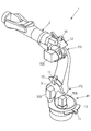
- the robot arm fixing device 11 corresponds to the first axis (JT1), the second axis (JT2), and the third axis (JT3) of the six-axis articulated robot 1. It is what was attached.
- the robot arm fixing device 11 may be attached to a part of a plurality of axes according to the magnitude and direction of an external force acting on the robot, or may be attached to all axes.
- shaft which attaches the fixing device 11, it selects according to the magnitude
- the robot arm fixing device 11 is attached to the outer surface of the robot arm 2, that is, outside the mechanism of the robot 1, it can be easily attached or detached.
- the external force is large in that it can be attached or removed as needed without being permanently installed. It is possible to respond to occasional changes.
- the robot arm 2 is supported by the joint casing 5 so as to be rotatable around the rotation axis L.
- a servo motor 7 and a speed reducer 8 constituting an arm drive mechanism 3 for rotationally driving the robot arm 2 are arranged inside the joint casing 5.
- the servo motor 7 has an electromagnetic brake 9 therein.
- the servo motor 7 constituting the arm drive mechanism 3 is controlled by the robot controller 10.
- the robot arm fixing device 11 is also controlled by the robot controller 10.
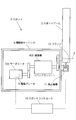
- FIG. 3 is a conceptual diagram of the structure near the joint of the robot arm fixing device 11 attached to the second axis (JT2) in the robot 1 according to the present embodiment.
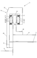
- FIG. 4 is a detailed cross-sectional view of a portion A in FIG. 3 and shows details of the structure of the robot fixing device 11.
- JT2 the second axis
- joint part or drive part (mechanism) of the second axis (JT2), the second robot arm or the like driven by being connected to the second axis drive part is simply referred to as the joint part or drive part (mechanism), robot Sometimes called an arm or the like.
- the robot arm fixing device 11 includes a flange (rotating member) 12, a locking mechanism 13, and other members.
- the flange 12 is attached to the base portion 4 of the robot arm 2 that is rotationally driven by the arm drive mechanism 3 provided at the joint portion of the second axis via the flange base portion 20, and accompanies the rotation of the robot arm 2. Then, it rotates together with the robot arm 2.
- the flange base 20 is attached to the base 4 of the robot arm 2 with bolts, screws, or the like (not shown).
- the locking mechanism 13 is attached to a mounting seat 6 provided in the joint casing (arm support portion) 5 via a locking mechanism base 23 extending from the housing 22, and the robot arm 2 rotates. Even so, it stops without accompanying the rotation. Note that the attachment of the locking mechanism base 23 to the attachment seat 6 is performed by bolts, screws, or the like (not shown).
- the locking mechanism 13 includes a pair of pistons (engagement portions) 18 that operate from both sides toward the center, and the pair of pistons 18 are disposed on both sides of the flange 12 with a predetermined gap. ing.
- the piston 18 introduces compressed air from a compressed air introduction system (not shown) into a diaphragm chamber 16 provided on the side opposite to the flange 12, whereby the diaphragm 15 is deformed, and thereby the inner periphery of the cylinder 21. It moves (operates) in the axial direction of the cylinder 21 along the surface and is pressed against the engagement surface 12 a of the flange 12. As a result, the flange 12 is locked (fixed) by the piston 18.
- a friction plate (engagement portion) 19 is provided on the surface of the piston 18 in order to improve the frictional force.
- the pressure receiving area of the piston can be increased, so that a large pressing force can be secured, and a highly reliable fixing mechanism can be realized.
- a dedicated rivet driving device or a rivet caulking device is attached to the end effector of the robot 1 and the operation is performed in a confined space. It becomes a specific thing assumed beforehand. For such work, it is sufficient that the robot arm 2 can be fixed in a limited range of rotation corresponding to a presumed work posture.
- the region that can be fixed by the robot arm fixing device 11 is limited to the rotation range of the operation axis corresponding to the posture assumed in advance. Instead, it has a fan shape (arc shape). Thereby, the vicinity of the joint portion can be made compact, and the placement or access of the robot 1 in the narrow space to be worked can be performed.
- a spring 17 is disposed on the outer periphery of the cylinder 21.
- the piston 18 is separated from the flange 12 by the return force of the spring 17 and returned to both ends in the cylinder 21.
- the number of springs may be one or more, and is appropriately selected or determined based on the size of the piston 18 or the cylinder 21, the required return force of the piston 18, or the like.
- the robot arm fixing device 11 is such that the piston 18 in the above embodiment is only one of the flanges 12.
- the piston 18, the cylinder 21, the spring 17 and the like in the locking mechanism 13 are basically halved compared to the above embodiment, and the compressed air supply system (pipe) and the like are simplified.
- the pressing force of the piston 18 against the flange 12 is uniform in the above embodiment, but in this modification example, only one is not uniform, so the plate thickness of the flange 12 is increased as necessary. To do.
- FIG. 7 shows a cross section BB in FIG.
- This modification is a modification of the modification shown in FIG. 5 and is a change of the direction of movement or pressing of the piston 18 in the modification by 90 degrees.
- the surface of the flange 12 against which the piston 18 is pressed is curved in a circular manner following the cylindrical surface of the joint casing 5 or the arm base 4, so that Depending on the radius of curvature, the pressing surface of the friction plate 19 against the flange 12 needs to be curved accordingly.
- the friction plate 19 is subdivided into a plurality of small pieces and arranged along the curvature of the arm base 4.
- the flange 12 and the flange base 20 are parallel to each other, so that a sufficiently large space cannot be secured.
- the flange base When it is difficult to arrange bolts and screws for connecting the portion 12 to the arm base portion 4, extend both ends of the flange base portion 20 longer than both ends of the flange 12, as shown in FIG.
- the flange base 20 and the arm base 4 are connected to each other at the extension.
- the robot arm fixing device 11 can directly fix the robot arm 2 without using a rotational drive force transmission mechanism, for example, the speed reducer 8, even if a large external force acts on the robot arm 2,
- the position of the positioned robot arm 2 can be maintained with high accuracy without being affected by backlash or the like.
- the robot arm fixing device 11 fixes the robot arm 2 independently of the brake for stopping and stopping the operation of the robot arm 2, and is not used for braking and stopping the operation of the robot arm 2. Since there is basically no wear, durability is improved and there is almost no need for maintenance.
- the robot arm fixing device 11 is independent from the drive mechanism 3 that drives the robot arm 2, the robot arm fixing device 11 can be attached only when necessary according to the target work, thereby reducing the cost of manufacturing the robot. In addition, the maintenance and inspection are facilitated, and there is no space restriction like the built-in brake, so a large fixing force can be secured and the robot arm fixing performance can be greatly improved.
- the robot arm 2 since it is sufficient that the robot arm 2 can be fixed to an external force corresponding to the work assumed in advance, the flange (rotating member) 12 and the locking mechanism 13 do not need to be provided over the entire circumference of the rotating shaft. It is sufficient to provide it only in the part. For this reason, it is possible to suppress the increase in size of the apparatus, and it is easy to remove and attach the apparatus, and the weight of the robot arm fixing apparatus 11 can be reduced.
- the end effector compressed air pipe can be made common, so that the piping around the robot can be simplified.
- the active driving power such as compressed air is used as the driving power of the locking mechanism 13 instead of the spring which is a passive mechanical force, the engaging force can be controlled and the reliability of the arm fixing can be controlled. Improves reliability and certainty.
- the member described above as the flange is not limited to the flange, and may be a member (rotating member) that is attached to the robot arm and rotates integrally with the rotation of the robot arm.
- a block-shaped member may be used.
- the locking mechanism is not limited to one using compressed air as driving power, but may be one using an electric mechanism or the like, and the member described as a piston in the above is not limited to the piston. Any member that is pressed against the rotating member to contact and fix may be sufficient, for example, a link mechanism or the like.
Landscapes
- Engineering & Computer Science (AREA)
- Robotics (AREA)
- Mechanical Engineering (AREA)
- Manipulator (AREA)
Abstract
本装置は、ロボットアーム(2)をその回転軸線周りに回転可能に支持するアーム支持部(5)に設けられた係止機構(11)と、回転軸線周りにロボットアーム(2)と一体に回転する回転部材(12)であって、係止機構(11)によって解放可能に係止されて回転方向の両方向において移動不能とされる回転部材(12)と、を備える。ロボットの動作停止時に、ロボットアームが位置決めされた所定の位置から変位することを防止できる。
Description
本発明は、ロボットアームを固定するためのロボットアーム固定装置および同装置を備えたロボットに関する。
産業用ロボットにおいては、例えば、サーボモータで構成された駆動源からの動力を、減速機を介してロボットアームに伝達してロボットアームを回転駆動する構成が採用されている。
サーボモータとしては、例えば、無励磁作動式電磁ブレーキ内蔵のサーボモータが使用される。このタイプのサーボモータを使用することにより、高速で動作するロボットアームを制動・停止させて高精度に位置決めしてその位置の保持を実現している(例えば、特許文献1)。
しかしながら、上述した従来のロボットにおいては、サーボモータからロボットアームに至る動力伝達経路において、減速機よりも上流側(サーボモータ側)に電磁ブレーキが配置されている。減速機は、その構造上、伝達機構に遊びが存在するので、電磁ブレーキによってサーボモータの出力軸を固定したとしても、減速機の伝達機構の遊び分(バックラッシュ相当分)は、ロボットアームの動作が許容される。
従って、電磁ブレーキを作動させてロボットアームが動作停止され位置決めされた後、例えばロボットアーム先端のエンドエフェクタに外力が作用した場合には、減速機のバックラッシュ相当分はロボットアームが押し込まれ、エンドエフェクタを所定の位置に保持することができない。
このため、エンドエフェクタを高い精度で位置決めしてその位置で確実に保持する必要がある場合には、従来のロボットでは対応できないことがあった。これは例えば、航空機の機体を製造する際のリベット打ち作業において問題になる可能性がある。
本発明は、上述した従来のロボットにおける問題点に鑑みなされたものであって、ロボットの動作停止時において、特にエンドエフェクタに大きな外力が作用した場合でも、位置決めされた所定の位置からロボットアームが変位することを防止できるロボットアーム固定装置および同装置を備えたロボットを提供することを目的とする。
上記課題を解決するために、本発明の第1の態様は、ロボットアームを固定するためのロボットアーム固定装置であって、前記ロボットアームをその回転軸線周りに回転可能に支持するアーム支持部に設けられた係止機構と、前記回転軸線周りに前記ロボットアームと一体に回転する回転部材であって、前記係止機構によって解放可能に係止されて前記回転方向の両方向において移動不能とされる回転部材と、を備えたことを特徴とする。
本発明の第2の態様は、第1の態様において、前記回転部材は、前記回転方向に延在する係合面を有し、前記係止機構は、前記係合面に対して解放可能に係合する係合部を有する、ことを特徴とする。
本発明の第3の態様は、第2の態様において、前記回転部材の前記係合面は、円弧状に形成されている、ことを特徴とする。
本発明の第4の態様は、第2または第3の態様において、前記係止機構は、前記係合部を圧縮空気により駆動するための駆動手段を有する、ことを特徴とする。
本発明の第5の態様は、第1乃至第4のいずれかの態様において、前記回転部材は、前記ロボットアームの外面に取り付けられている、ことを特徴とする。
本発明の第6の態様によるロボットは、ロボットアームと、前記ロボットアームをその回転軸線周りに回転可能に支持するアーム支持部と、第1乃至第5のいずれかの態様に記載のロボットアーム固定装置と、を備えたことを特徴とする。
本発明の第7の態様は、第6の態様において、前記ロボットアームは、複数の回転軸線を有し、前記ロボットアーム固定装置は、前記複数の回転軸線のうちの少なくとも2つの回転軸線それぞれに対応して設けられている、ことを特徴とする。
本発明の第8の態様は、第6または第7の態様において、前記ロボットアームの駆動を制御するためのロボットコントローラをさらに備え、前記係止機構は、前記ロボットコントローラによって制御される、ことを特徴とする。
以下、本発明の一実施形態によるロボットアーム固定装置を備えたロボットについて、図面を参照して説明する。
図1に示したように本実施形態は、ロボットアーム固定装置11を、6軸多関節ロボット1の第1軸(JT1)、第2軸(JT2)および第3軸(JT3)に対応して装着したものである。なお、ロボットアーム固定装置11は、ロボットに作用する外力の大きさや方向に応じて、複数の軸のうちの一部の軸に取り付けてもよく、またすべての軸に取り付けることもでき、ロボットアーム固定装置11を取り付ける軸については、外力の大きさや方向、必要とされる位置決め・固定精度に応じて選択される。
図1に示したように、ロボットアーム固定装置11は、ロボットアーム2の外面、すなわちロボット1の機構外部に取り付けられるため、容易に取り付け又は取り外しが可能である。このため、関節部ないしアーム駆動機構の内部に設置される電磁ブレーキと異なり、交換等が容易であることに加え、常設とせずに必要に応じ取り付け又は取り外しが可能である点で、外力の大きさなどに臨機応変に対応が可能である。
図2に示したように、ロボットアーム2は、関節部ケーシング5によって回転軸線L周りに回転可能に支持されている。関節部ケーシング5の内部には、ロボットアーム2を回転駆動するためのアーム駆動機構3を構成するサーボモータ7および減速機8が配置されている。サーボモータ7は、その内部に電磁ブレーキ9を有する。
アーム駆動機構3を構成するサーボモータ7は、ロボットコントローラ10によって制御される。ロボットアーム固定装置11もまた、ロボットコントローラ10によって制御される。
図3は、本実施形態によるロボット1における第2軸(JT2)に取り付けたロボットアーム固定装置11の関節部付近の構造概念図である。また、図4は、図3におけるA部の詳細断面図であって、ロボット固定装置11の構造の詳細を示すものである。以下、これらの図面に基づいて、ロボットアーム固定装置11の構造の詳細および作動原理や機能を説明する。
なお、以下では、第2軸(JT2)の関節部や駆動部(機構)、第2軸駆動部に連結して駆動される第2ロボットアーム等を単に関節部や駆動部(機構)、ロボットアーム等と呼ぶことがある。
ロボットアーム固定装置11は、フランジ(回転部材)12および係止機構13その他の部材等から構成されている。
フランジ12は、第2軸の関節部に設けられているアーム駆動機構3によって回転駆動されるロボットアーム2の基底部4に、フランジ基底部20を介して取り付けられ、ロボットアーム2の回転に随伴してロボットアーム2と一体で回転する。なお、フランジ基底部20のロボットアーム2の基底部4への取り付けは、ボルトやネジ等(図示を省略)により行われる。
一方、係止機構13は、そのハウジング22から延在する係止機構基底部23を介して、関節部ケーシング(アーム支持部)5に設けられた取付座6に取り付けられ、ロボットアーム2が回転してもその回転には随伴せずに停止している。なお、係止機構基底部23の取付座6への取り付けは、ボルトやネジ等(図示を省略)により行われる。
係止機構13は、両側から中央部に向けて動作する一対のピストン(係合部)18を内包しており、これら一対のピストン18は、所定の間隙を持ってフランジ12の両側に配置されている。ピストン18は、それぞれ、フランジ12と反対側に設けられたダイヤフラム室16に圧縮空気導入系(図示を省略)から圧縮空気を導入することにより、ダイヤフラム15が変形し、これによりシリンダ21の内周面に沿ってシリンダ21の軸方向に移動(動作)してフランジ12の係合面12aに押し付けられる。その結果、フランジ12がピストン18によりロック(固定)される。
これにより、ロボットアーム2の動作がロック(固定)されるため、ロボットアーム2が回転する方向に外力を受けても、ロボットアーム2は変位しない。なお、ピストン18の押し付けによるフランジ12のロックの効果を高めるため、摩擦力向上のためにピストン18の表面には摩擦板(係合部)19が備えられている。
本実施形態においては、ダイヤフラム15を採用しているため、ピストンの受圧面積を大きく取れるので、大きな押し付け力の確保が可能であり、確実性の高い固定機構が実現できる。
また、本実施形態では、能動的な圧縮空気を駆動動力とした押し付け方式を採用しているため、フランジ12と両側のピストン18との間隙が異なっていても、原理的に両側のピストン18によるフランジ12への押し付け力は均等となる。フランジ12および係止機構13をロボット1の作業現場にてロボットオペレータ等が取り付けることを考慮すると、現実には、フランジ12とその両側のピストン13との間隙を正確に同一にするのは難しいことが多いと考えられる。この点、本実施形態によれば、現場におけるロボットアーム固定装置11の取り付け等の簡素化が図れるとともに、フランジ12の板厚を薄くすることが可能である。
なお、例えば、航空機の機体のリベット打ちのような作業の場合には、ロボット1のエンドエフェクタに専用リベット打ち装置又はリベットカシメ装置を取り付けて、かつ狭隘空間で作業する一方、作業の姿勢は、予め想定した特定のものとなる。このような作業に対して、ロボットアーム2は、予め想定した作業姿勢に対応した回転範囲に限定して固定できれば十分である。
そこで、本実施形態においては、図1に示すように、ロボットアーム固定装置11により固定できる領域を、予め想定される姿勢に対応する動作軸の回転範囲に限定することとして、フランジ12を円環ではなく、扇形(円弧状)としている。これにより、関節部付近をコンパクトとすることができ、作業対象の狭隘空間内へのロボット1の配置又はアクセスが可能となる。
シリンダ21の外周部には、バネ17が配置されている。ダイヤフラム室16に圧縮空気が供給されていない又は圧縮空気が抜かれた状態では、このバネ17の戻り力により、ピストン18はフランジ12から引き離され、シリンダ21内の両端に戻されている。
なお、バネの個数は、1つ以上であればよく、ピストン18又はシリンダ21の大きさ、必要とされるピストン18の戻り力などから適宜選定又は決定される。
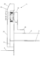
次に、上記実施形態の一変形例によるロボットアーム固定装置11を図5に示す。
本変形例は、基本的に上記実施形態と同様であり、以下においては、主として上記実施形態と異なる部分を中心として説明し、図5における符号も基本的に上記実施形態に合わせて使用する。
本変形例実施形態に係るロボットアーム固定装置11は、上記実施形態におけるピストン18をフランジ12の一方のみとしたものである。
したがって、本変形例では、上記実施形態に比べ、係止機構13におけるピストン18、シリンダ21、バネ17等が基本的に半減し、圧縮空気供給系(管)等が簡素化する。なお、ピストン18のフランジ12への押し付け力が、上記実施形態では均等であったのに対して、本変形例では一方のみとなり不均等となるため、フランジ12の板厚を必要に応じ、厚くする。
次に、上記実施形態の他の変形例に係るロボットアーム固定装置11を図6に示す。また、図6における断面B-Bを図7に示す。
本変形例は、図5に示した上記変形例をさらに変形させたものであり、上記変形例におけるピストン18の移動ないし押し付けの方向を90度変更したものである。なお、本変形例においては、図7に示すように、ピストン18が押し付けられるフランジ12の表面が、関節部ケーシング5ないしアーム基底部4の円筒面にならって円形に湾曲しているので、その曲率半径の大きさによっては、摩擦板19のフランジ12への押し付け面をそれに応じた湾曲を持たせる必要がある。または、摩擦板19を小さな複数の小片に細分して、アーム基底部4の湾曲に沿わせて配置する。
また、本変形例においては、フランジ12とフランジ基底部20とが平行となるため、その間の空間を十分大きく確保できない場合であって、フランジ12とフランジ基底部20との間の空間においてフランジ基底部12をアーム基底部4と接続するためのボルトやネジの配置が困難である場合には、図7に示すように、フランジ基底部20の両端部をフランジ12の両端部より長く延長して、その延長部において、フランジ基底部20とアーム基底部4とを接続する。
なお、本変形例においては、前記の点を除いて、上記変形例と基本的に同様である。
上述した実施形態およびその変形例によれば、次の効果が実現できる。
ロボットアーム固定装置11は、回転駆動力の伝達機構、例えば減速機8を介さずにロボットアーム2を直接固定することができるので、大きな外力がロボットアーム2に作用しても、減速機8のバックラッシュ等の影響を受けずに、位置決めされたロボットアーム2の位置を高精度に維持することができる。
また、ロボットアーム固定装置11は、ロボットアーム2の動作の制動と停止のためのブレーキと独立してロボットアーム2を固定するものであり、ロボットアーム2の動作の制動と停止に使用されないので、基本的に摩耗がないことから、耐久性が向上し、保守の必要性もほとんどない。
また、ロボットアーム固定装置11は、ロボットアーム2を駆動する駆動機構3とは独立したものであるので、対象作業に応じて必要な場合にのみ取り付けることが可能であり、ロボット製造のコストダウンが図れるとともに、保守や点検も容易となり、内蔵ブレーキのような空間的制約がないため、大きな固定力が確保でき、ロボットアーム固定性能が大幅に向上できる。
また、予め想定する作業に対応した外力に対してロボットアーム2が固定できれば足りるので、フランジ(回転部材)12と係止機構13は、回転軸の全周に亘って設ける必要はなく、特定の部分にのみ設ければ十分である。このため、装置の大型化を抑止できるとともに、取り外しや取り付け等も容易となり、ロボットアーム固定装置11の重量の軽減も実現できる。
さらに、ロボット1がエンドエフェクタとして圧縮空気で作動する工具等を使用する場合には、エンドエフェクタ用圧空パイプを共通化できるので、ロボット周囲の配管取り回しが簡素化できる。また、受動的な機械力であるバネではなく、圧縮空気等の能動的な駆動動力を係止機構13の駆動動力として使用するため、係合力を制御することが可能であり、アーム固定の信頼性・確実性が向上する。
以上、本発明の一実施形態およびその変形例について説明したが、本発明は、それらに限定されるものではなく、適宜変形することができる。例えば、上記においてフランジとして説明された部材は、フランジに限定されるものではなく、ロボットアームに取り付けられてロボットアームの回転に随伴して一体に回転する部材(回転部材)であれば足り、例えばブロック状の部材でもよい。
また、係止機構は、圧縮空気を駆動動力とするものに限定されず、電動機構等を利用したものでもよく、さらに、上記においてピストンとして説明された部材は、ピストンに限定されるものではなく、回転部材に押し付けられ接触・固定する部材であれば足り、例えばリンク機構等でもよい。
1 ロボット
2 ロボットアーム
3 アーム駆動機構
4 アーム基底部
5 関節部ケーシング
6 取付座
7 サーボモータ
8 減速機
9 電磁ブレーキ
10 ロボットコントローラ
11 ロボットアーム固定装置
12 フランジ
12a フランジの係合面
13 係止機構
15 ダイヤフラム
16 ダイヤフラム室
17 バネ
18 ピストン(係合部)
19 摩擦板(係合部)
20 フランジ基底部
21 シリンダ
22 ハウジング
23 係止機構基底部
L 回転軸線
2 ロボットアーム
3 アーム駆動機構
4 アーム基底部
5 関節部ケーシング
6 取付座
7 サーボモータ
8 減速機
9 電磁ブレーキ
10 ロボットコントローラ
11 ロボットアーム固定装置
12 フランジ
12a フランジの係合面
13 係止機構
15 ダイヤフラム
16 ダイヤフラム室
17 バネ
18 ピストン(係合部)
19 摩擦板(係合部)
20 フランジ基底部
21 シリンダ
22 ハウジング
23 係止機構基底部
L 回転軸線
Claims (8)
- ロボットアームを固定するためのロボットアーム固定装置であって、
前記ロボットアームをその回転軸線周りに回転可能に支持するアーム支持部に設けられた係止機構と、
前記回転軸線周りに前記ロボットアームと一体に回転する回転部材であって、前記係止機構によって解放可能に係止されて前記回転方向の両方向において移動不能とされる回転部材と、を備えたロボットアーム固定装置。 - 前記回転部材は、前記回転方向に延在する係合面を有し、
前記係止機構は、前記係合面に対して解放可能に係合する係合部を有する、請求項1記載のロボットアーム固定装置。 - 前記回転部材の前記係合面は、円弧状に形成されている、請求項2記載のロボットアーム固定装置。
- 前記係止機構は、前記係合部を圧縮空気により駆動するための駆動手段を有する、請求項2または3に記載のロボットアーム固定装置。
- 前記回転部材は、前記ロボットアームの外面に取り付けられている、請求項1乃至4のいずれか一項に記載のロボットアーム固定装置。
- ロボットアームと、
前記ロボットアームをその回転軸線周りに回転可能に支持するアーム支持部と、
請求項1乃至5のいずれか一項に記載のロボットアーム固定装置と、を備えたロボット。 - 前記ロボットアームは、複数の回転軸線を有し、
前記ロボットアーム固定装置は、前記複数の回転軸線のうちの少なくとも2つの回転軸線それぞれに対応して設けられている、請求項6記載のロボット。 - 前記ロボットアームの駆動を制御するためのロボットコントローラをさらに備え、
前記係止機構は、前記ロボットコントローラによって制御される、請求項6または7に記載のロボット。
Applications Claiming Priority (2)
| Application Number | Priority Date | Filing Date | Title |
|---|---|---|---|
| JP2015069408A JP2016187858A (ja) | 2015-03-30 | 2015-03-30 | ロボットアーム固定装置およびロボット |
| JP2015-069408 | 2015-03-30 |
Publications (1)
| Publication Number | Publication Date |
|---|---|
| WO2016158614A1 true WO2016158614A1 (ja) | 2016-10-06 |
Family
ID=57005045
Family Applications (1)
| Application Number | Title | Priority Date | Filing Date |
|---|---|---|---|
| PCT/JP2016/059223 Ceased WO2016158614A1 (ja) | 2015-03-30 | 2016-03-23 | ロボットアーム固定装置およびロボット |
Country Status (2)
| Country | Link |
|---|---|
| JP (1) | JP2016187858A (ja) |
| WO (1) | WO2016158614A1 (ja) |
Cited By (2)
| Publication number | Priority date | Publication date | Assignee | Title |
|---|---|---|---|---|
| US11345021B2 (en) | 2019-05-24 | 2022-05-31 | Fanuc Corporation | Arm fixing device |
| WO2025149978A1 (en) * | 2024-01-10 | 2025-07-17 | National Research Council Of Canada | Exobrake joint splint, and exostructure, for robotic arms |
Families Citing this family (4)
| Publication number | Priority date | Publication date | Assignee | Title |
|---|---|---|---|---|
| JP6465942B2 (ja) * | 2016-11-29 | 2019-02-06 | 株式会社メディカロイド | ロボット手術台およびロボット治療台 |
| JP6457994B2 (ja) * | 2016-11-29 | 2019-01-23 | 株式会社メディカロイド | ロボット手術台 |
| JP6572254B2 (ja) | 2017-05-02 | 2019-09-04 | ファナック株式会社 | アーム固定装置および減速機交換方法 |
| KR102188407B1 (ko) * | 2019-01-31 | 2020-12-08 | 한국과학기술원 | 회전 고정 장치 및 이를 포함하는 2 자유도 회전 암 |
Citations (5)
| Publication number | Priority date | Publication date | Assignee | Title |
|---|---|---|---|---|
| JPH0333089U (ja) * | 1982-11-10 | 1991-04-02 | ||
| JPH04141394A (ja) * | 1990-09-29 | 1992-05-14 | Sanyo Electric Co Ltd | 産業用ロボット |
| JPH0588891U (ja) * | 1992-05-26 | 1993-12-03 | マツダ株式会社 | ワークの保持装置 |
| JP2013035098A (ja) * | 2011-08-08 | 2013-02-21 | Yaskawa Electric Corp | ロボット |
| JP2013208344A (ja) * | 2012-03-30 | 2013-10-10 | Equos Research Co Ltd | 歩行補助装置 |
-
2015
- 2015-03-30 JP JP2015069408A patent/JP2016187858A/ja active Pending
-
2016
- 2016-03-23 WO PCT/JP2016/059223 patent/WO2016158614A1/ja not_active Ceased
Patent Citations (5)
| Publication number | Priority date | Publication date | Assignee | Title |
|---|---|---|---|---|
| JPH0333089U (ja) * | 1982-11-10 | 1991-04-02 | ||
| JPH04141394A (ja) * | 1990-09-29 | 1992-05-14 | Sanyo Electric Co Ltd | 産業用ロボット |
| JPH0588891U (ja) * | 1992-05-26 | 1993-12-03 | マツダ株式会社 | ワークの保持装置 |
| JP2013035098A (ja) * | 2011-08-08 | 2013-02-21 | Yaskawa Electric Corp | ロボット |
| JP2013208344A (ja) * | 2012-03-30 | 2013-10-10 | Equos Research Co Ltd | 歩行補助装置 |
Cited By (2)
| Publication number | Priority date | Publication date | Assignee | Title |
|---|---|---|---|---|
| US11345021B2 (en) | 2019-05-24 | 2022-05-31 | Fanuc Corporation | Arm fixing device |
| WO2025149978A1 (en) * | 2024-01-10 | 2025-07-17 | National Research Council Of Canada | Exobrake joint splint, and exostructure, for robotic arms |
Also Published As
| Publication number | Publication date |
|---|---|
| JP2016187858A (ja) | 2016-11-04 |
Similar Documents
| Publication | Publication Date | Title |
|---|---|---|
| WO2016158614A1 (ja) | ロボットアーム固定装置およびロボット | |
| JP6836248B2 (ja) | 関節ユニット、ロボットアーム及びロボット | |
| JP6670289B2 (ja) | 電気機械式ブレーキキャリパーアクチュエータ | |
| US4693665A (en) | Large force multi-axis manipulating arm unit, especially for use as an industrial robot | |
| CN114083577B (zh) | 刹车组件、关节驱动器和机器人 | |
| JP2011229331A (ja) | 制動機能付モータ、及びそれを備えるロボット | |
| JP2011240440A (ja) | リンク作動装置 | |
| US11433532B2 (en) | Robot joint structure | |
| JP2022006209A (ja) | アクチュエータ及びブレーキ | |
| CN103906947A (zh) | 平行连杆机构、等速万向节和连杆动作装置 | |
| JP2659998B2 (ja) | リニアアクチュエータ | |
| CN105835085A (zh) | 机器人 | |
| WO2014185373A1 (ja) | リンク作動装置 | |
| KR20180060264A (ko) | 다관절 로봇의 스토퍼장치 | |
| JP5911697B2 (ja) | パラレルリンク機構、等速自在継手、およびリンク作動装置 | |
| JP2014083613A (ja) | ロボット | |
| US20220281124A1 (en) | Brake system for articulated mechanism | |
| CN114174020B (zh) | 用于机器人的驱动装置的制动设备 | |
| WO2015136648A1 (ja) | パラレルリンク機構、ロボットおよび組立装置 | |
| CN104827486B (zh) | 一种仿人机器人柔性关节 | |
| CN109807858B (zh) | 大变形驱动的空间两转一平弹性连杆并联机构 | |
| KR102791834B1 (ko) | 모터용 브레이크 조립체 | |
| CN116557452B (zh) | 一种可实现共轴轴筒离合与制动装置 | |
| JP7824183B2 (ja) | 作業機械システム | |
| CN119839887A (zh) | 一种电机制动结构及其机器人关节 |
Legal Events
| Date | Code | Title | Description |
|---|---|---|---|
| 121 | Ep: the epo has been informed by wipo that ep was designated in this application |
Ref document number: 16772495 Country of ref document: EP Kind code of ref document: A1 |
|
| NENP | Non-entry into the national phase |
Ref country code: DE |
|
| 122 | Ep: pct application non-entry in european phase |
Ref document number: 16772495 Country of ref document: EP Kind code of ref document: A1 |