WO2016158560A1 - 車両用のシート装置 - Google Patents
車両用のシート装置 Download PDFInfo
- Publication number
- WO2016158560A1 WO2016158560A1 PCT/JP2016/058953 JP2016058953W WO2016158560A1 WO 2016158560 A1 WO2016158560 A1 WO 2016158560A1 JP 2016058953 W JP2016058953 W JP 2016058953W WO 2016158560 A1 WO2016158560 A1 WO 2016158560A1
- Authority
- WO
- WIPO (PCT)
- Prior art keywords
- seat
- adjustment
- clutch
- slide mechanism
- transmission member
- Prior art date
- Legal status (The legal status is an assumption and is not a legal conclusion. Google has not performed a legal analysis and makes no representation as to the accuracy of the status listed.)
- Ceased
Links
Images



Classifications
-
- B—PERFORMING OPERATIONS; TRANSPORTING
- B60—VEHICLES IN GENERAL
- B60N—SEATS SPECIALLY ADAPTED FOR VEHICLES; VEHICLE PASSENGER ACCOMMODATION NOT OTHERWISE PROVIDED FOR
- B60N2/00—Seats specially adapted for vehicles; Arrangement or mounting of seats in vehicles
- B60N2/02—Seats specially adapted for vehicles; Arrangement or mounting of seats in vehicles the seat or part thereof being movable, e.g. adjustable
- B60N2/04—Seats specially adapted for vehicles; Arrangement or mounting of seats in vehicles the seat or part thereof being movable, e.g. adjustable the whole seat being movable
- B60N2/12—Seats specially adapted for vehicles; Arrangement or mounting of seats in vehicles the seat or part thereof being movable, e.g. adjustable the whole seat being movable slidable and tiltable
-
- B—PERFORMING OPERATIONS; TRANSPORTING
- B60—VEHICLES IN GENERAL
- B60N—SEATS SPECIALLY ADAPTED FOR VEHICLES; VEHICLE PASSENGER ACCOMMODATION NOT OTHERWISE PROVIDED FOR
- B60N2/00—Seats specially adapted for vehicles; Arrangement or mounting of seats in vehicles
- B60N2/02—Seats specially adapted for vehicles; Arrangement or mounting of seats in vehicles the seat or part thereof being movable, e.g. adjustable
- B60N2/04—Seats specially adapted for vehicles; Arrangement or mounting of seats in vehicles the seat or part thereof being movable, e.g. adjustable the whole seat being movable
- B60N2/14—Seats specially adapted for vehicles; Arrangement or mounting of seats in vehicles the seat or part thereof being movable, e.g. adjustable the whole seat being movable rotatable, e.g. to permit easy access
-
- B—PERFORMING OPERATIONS; TRANSPORTING
- B60—VEHICLES IN GENERAL
- B60N—SEATS SPECIALLY ADAPTED FOR VEHICLES; VEHICLE PASSENGER ACCOMMODATION NOT OTHERWISE PROVIDED FOR
- B60N2/00—Seats specially adapted for vehicles; Arrangement or mounting of seats in vehicles
- B60N2/02—Seats specially adapted for vehicles; Arrangement or mounting of seats in vehicles the seat or part thereof being movable, e.g. adjustable
- B60N2/20—Seats specially adapted for vehicles; Arrangement or mounting of seats in vehicles the seat or part thereof being movable, e.g. adjustable the back-rest being tiltable, e.g. to permit easy access
Definitions
- the present invention relates to a vehicle seat device.
- a seat device for a vehicle has a seat slide mechanism that can be switched between a locked state that restricts the position adjustment of the vehicle seat and an unlocked state that allows this, and a locked state that restricts the angle adjustment of the seat back. And a seat recliner mechanism that can be switched between an unlocked state that permits this.
- the walk-in mechanism includes a wire and a rotating member. One end of the wire is connected to the seat recliner mechanism, and the other end of the wire is connected to the rotating member.
- the rotating member is displaceable between the first rotating position and the second rotating position. The rotation member is separated from the lock member of the seat slide mechanism when the rotation member is located at the first rotation position. When the rotation member is displaced to the second rotation position, the rotation member presses the lock member to a position where the seat slide mechanism is switched from the locked state to the unlocked state.
- the rotating member When the seat back is tilted so as to be close to the seat portion, the rotating member is displaced from the first rotating position to the second rotating position through the wire. And adjustment of the front-back position of a vehicle seat is permitted because a rotation member presses a lock member with the rotation.
- the rotating member rotates more than necessary. In this case, since the contact pressure between the rotating member and the lock member is increased, there is a possibility that the two members will not be separated from each other. On the other hand, if the wire is too long, another rotating member for the slide function may not rotate even if the rotating member for the recliner function rotates. In this case, the walk-in function is not exhibited. Furthermore, since the wire tends to be stretched with aging, it is difficult to adjust the walk-in mechanism.
- An object of the present invention is to provide a vehicle seat device having an easily adjustable walk-in mechanism.
- a vehicle seat that solves the above-described problem is a seat slide mechanism that adjusts the position of a vehicle seat, the seat slide being switchable between an adjustment regulation state that regulates position adjustment and an adjustment permission state that permits position adjustment.
- a seat recliner mechanism that adjusts the angle of the mechanism and the seat back, the seat recliner mechanism being switchable between an adjustment restricting state that restricts angle adjustment and an adjustment permissible state that permits angle adjustment; and the seat slide
- a walk-in mechanism that is interposed between a mechanism and the seat recliner mechanism and interlocks the two mechanisms, and the walk-in mechanism displaces in conjunction with a change in the angle of the seat back.
- a second transmission member that is displaced between a position and a position at which the seat slide mechanism is pressed to switch to the adjustment-permitted state, and is interposed between the first transmission member and the second transmission member.
- a clutch that switches whether to transmit displacement from the first transmission member to the second transmission member in accordance with a contact pressure between the second transmission member and the seat slide mechanism.
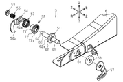
- the disassembled perspective view of the clutch mechanism in the seat apparatus of FIG. (A) is a side view of the clutch mechanism, (b) is a top view of the clutch mechanism, and (c) is a front view of the clutch mechanism.
- (A) is an end view of the main part of the clutch mechanism in a state where rotation is transmitted, and (b) is an end view of the main part of the clutch mechanism in a state where rotation is not transmitted.
- (A) is a side view of the main part of the seat slide mechanism in the slide lock state
- (b) is a side view of the main part of the seat slide mechanism in the intermediate state
- (c) is a main part of the seat slide mechanism in the slide unlock state
- (D) is a side view of the principal part of the seat slide mechanism in an over-pressed state.
- a vehicle seat device 1 adjusts a seat slide mechanism 2 that adjusts the longitudinal position of a vehicle seat including a seat cushion and a seat back, and an angle of the seat back with respect to the seat cushion. And a seat recliner mechanism 3. Further, the vehicle seat device 1 includes a walk-in mechanism 4 that connects these two mechanisms so that the seat slide mechanism 2 and the seat recliner mechanism 3 are interlocked.
- the seat slide mechanism 2 includes a lower rail 21 that is fixed to the vehicle floor and extends in the front-rear direction, and an upper rail 22 that is displaceable with respect to the lower rail 21. And a slide lock portion 23 attached to the upper rail 22.
- the slide lock portion 23 includes an operation lever 24 that is inserted between the lower rail 21 and the upper rail 22.
- the operation lever 24 is supported by the upper rail 22 so as to be swingable at a swing center portion 24a located at the center in the longitudinal direction.
- the slide lock portion 23 includes an engagement portion 25 that is fixed to an end portion on the rear side of the operation lever 24 and selectively engages with an engagement claw (not shown) arranged side by side in the longitudinal direction of the lower rail 21. .
- the engaging portion 25 is displaced between a lock position (see FIG. 5A) and an unlock position (see FIG. 5C).
- a lock position see FIG. 5A
- an unlock position see FIG. 5C.
- the engaging portion 25 is disposed at the lock position and engages with an engaging claw (not shown).
- the engaging portion 25 is disposed at the unlock position and does not engage with an engaging claw (not shown).
- the slide lock portion 23 includes a lever spring 26 that urges the operation lever 24 upward behind the swing center portion 24a. Due to the urging force of the lever spring 26, the engaging portion 25 is always held in the locked position.
- the slide lock portion 23 When the engaging portion 25 is positioned at the lock position, the slide lock portion 23 is in a slide lock state that restricts the displacement of the upper rail 22 relative to the lower rail 21. When the engagement portion 25 is located at the unlock position, the slide lock portion 23 is in a slide unlock state that allows displacement of the upper rail 22 relative to the lower rail 21. That is, the seat slide mechanism 2 can be selectively switched between an adjustment restriction state that restricts the position adjustment of the vehicle seat and an adjustment permission state that permits the position adjustment of the vehicle seat.
- the engaging portion 25 comes into contact with the lower rail 21 from above when located at the unlock position.
- the contact prevents the operating lever 24 from swinging so that the engaging portion 25 is displaced downward from the unlock position.
- the seat recliner mechanism 3 includes a rear end portion of the seat cushion frame 6 and a lower end portion of a seat back frame 7 (seat back) that serves as a skeleton of the seat back.
- a rotating bracket 8 that rotatably supports both of them is provided.
- the seat recliner mechanism 3 is manually operated to selectively switch the seat recliner mechanism 3 between a state in which the rotation of the seat back frame 7 relative to the seat cushion frame 6 and a state in which the rotation is restricted.
- a lever (not shown) and a spring (not shown) that urges the seat back frame 7 so that the seat back frame 7 comes close to the seat cushion frame 6 and so-called seat back is moved forward.
- the seat recliner mechanism 3 When a lever (not shown) is operated, the seat recliner mechanism 3 is switched from a state where the rotation of the seat back frame 7 relative to the seat cushion frame 6 is restricted to a state where this is allowed. When the rotation of the seat back frame 7 with respect to the seat cushion frame 6 is allowed, the seat back frame 7 is moved forward by an urging force of a spring (not shown). In other words, the seat recliner mechanism 3 can be switched between an adjustment regulation state that regulates the angle adjustment of the seat back and an adjustment permission state that permits the angle adjustment of the seat back.
- the walk-in mechanism 4 includes a rotation transmission mechanism 41 attached to the seat back frame 7 and a clutch mechanism 5 attached to the seat cushion frame 6. Prepare.
- the rotation transmission mechanism 41 includes a winding unit 42 and a wire cable 43.
- One end portion of the wire cable 43 is fixed to the winding portion 42, and the other end portion of the wire cable 43 is fixed to a rotation lever 57 described later.
- the winding part 42 is a member that rotates in conjunction with the rotating bracket 8.
- the winding portion 42 rotates in the counterclockwise direction when the seat back frame 7 is tilted forward from a set angle. Thereby, the wire cable 43 is pulled back.
- the winding portion 42 rotates clockwise and allows the wire cable 43 to return to the front.
- the rotation transmission mechanism 41 corresponds to a first transmission member that is displaced in conjunction with a change in the angle of the seat back.
- the clutch mechanism 5 includes a first clutch member 51, a second clutch member 52, a spiral spring 53, a pressing lever 54, and a coil spring 55.
- the first clutch member 51 includes a first shaft portion 61, a first clutch plate 62, a second shaft portion 63, and a third shaft portion 64.
- the first shaft portion 61 is a column extending in the left-right direction, and has an outer diameter slightly smaller than the inner diameter of the hole portion 6a penetrating the seat cushion frame 6 in the left-right direction.
- the first shaft portion 61 is rotatably inserted into the hole 6a.
- a rotation lever 57 is fixed to the left end portion of the first shaft portion 61.
- a washer 58 is interposed between the rotation lever 57 and the seat cushion frame 6.
- the first clutch plate 62 is a disc having the same axis as the first shaft portion 61, and continues to the right end portion of the first shaft portion 61. As shown in FIGS. 4 (a) and 4 (b), the right surface of the first clutch plate 62 constitutes a first clutch surface 62a including a plurality of inclined surfaces continuously arranged in a stepped manner in the circumferential direction. is doing. The plurality of inclined surfaces are inclined with respect to a surface orthogonal to the rotation axis of the first clutch plate 62 so as to increase toward the rear side in the counterclockwise direction, and are disposed at equal angular intervals over the entire circumferential direction. ing.
- the second shaft portion 63 is a cylinder having the same axis as the first shaft portion 61, and is continuous with the right surface of the first clutch plate 62, that is, the first clutch surface 62 a.
- the third shaft portion 64 is a screw shaft that is coaxial with the first shaft portion 61, and continues to the right end of the second shaft portion 63.
- the second clutch member 52 has a cylindrical portion 71 and a second clutch plate 72.
- the cylindrical portion 71 has an inner diameter slightly larger than the outer diameter of the second shaft portion 63 and smaller than the outer diameter of the first clutch plate 62.
- the second clutch plate 72 is a flange that is continuous with the left end of the cylindrical portion 71.
- the left surface of the second clutch plate 72 that is, the surface facing the first clutch surface 62a constitutes a second clutch surface 72a including a plurality of inclined surfaces continuously arranged in a stepped manner in the circumferential direction.
- the plurality of inclined surfaces are inclined with respect to a surface orthogonal to the rotation axis of the second clutch plate 72 so as to be higher toward the leading side in the counterclockwise direction, and are disposed at equal angular intervals over the entire circumferential direction. ing. Note that the inclination angle and the number of the inclined surfaces constituting the second clutch surface 72a are the same as the inclination angle and the number of the inclined surfaces constituting the first clutch surface 62a.
- the second clutch member 52 is attached to the first clutch member 51 in a state where the second shaft portion 63 is inserted through the cylindrical portion 71 and the second clutch plate 72.
- the spiral spring 53 has an inner diameter that is larger than the outer diameter of the cylindrical portion 71 and smaller than the outer diameter of the second clutch plate 72.
- One end of the spiral spring 53 is fixed to the seat cushion frame 6, and the other end of the spiral spring 53 is fixed to the pressing lever 54.
- the spiral spring 53 biases the pressing lever 54 so as to rotate in the clockwise direction.
- the spiral spring 53 is extrapolated to the cylindrical portion 71.
- the pressing lever 54 is an L-shaped plate material and has a mounting hole 54a penetrating in the left-right direction at the upper end thereof.
- the mounting hole 54 a is set equal to the inner diameter of the cylindrical portion 71.
- the lower end of the pressing lever 54 is a pressing end 54b.
- the pressing lever 54 is fixed to the right end of the cylindrical portion 71 in a state where the second shaft portion 63 is inserted into the mounting hole 54a. That is, the pressing lever 54 rotates integrally with the second clutch member 52. 5A to 5D, the pressing lever 54 is located above the operation lever 24. The pressing lever 54 is displaced between a non-pressing position separated from the operating lever 24 and a pressing position pressing the operating lever 24 by the rotation of the second clutch member 52. Note that the pressing lever 54 corresponds to a second transmission member.
- the coil spring 55 has an inner diameter slightly larger than that of the third shaft portion 64.
- the coil spring 55 is elastically compressed between the nut 59 and the pressing lever 54 by screwing the nut 59 onto the third shaft portion 64.
- the elastic force of the coil spring 55 acts on the second clutch member 52 via the pressing lever 54. That is, the second clutch member 52 is pressed toward the first clutch member 51.
- the first clutch surface 62a contact surface of the first clutch member 51
- the second clutch surface 72a contact surface of the second clutch member 52
- the first clutch member 51 corresponds to the first rotating member
- the second clutch member 52 corresponds to the second rotating member.
- the coil spring 55 corresponds to an urging member.
- the pressing lever 54 that rotates integrally with the second clutch member 52 also rotates counterclockwise, and the operating lever 24 is pressed from the non-pressing position. Rotate until. As a result, the rear end of the operation lever 24 is pushed down, and the seat slide mechanism 2 shifts from the slide lock state to the slide unlock state. Thereby, the front-rear position of the seat can be adjusted.
- the inclined surface constituting the first clutch surface 62a is inclined so as to be higher toward the rear side in the counterclockwise direction, and the inclined surface constituting the second clutch surface 72a is counterclockwise. Inclines so that the leading side in the direction becomes higher. Accordingly, when the first clutch member 51 rotates in the counterclockwise direction while the rotation of the second clutch member 52 in the counterclockwise direction is restricted, the second clutch member 52 is caused by the inclined surfaces that are in contact with each other. The force to the right acts on.
- the coil spring 55 is elastically compressed by the rightward force, and the second clutch member 52 is displaced rightward.
- the clutch mechanism 5 is provided in the walk-in mechanism 4.
- the clutch mechanism 5 and the second clutch surface 62a Surface contact with the clutch surface 72a is eliminated, and transmission of rotation from the first clutch member 51 to the second clutch member 52 is interrupted.
- the clutch mechanism 5 blocks the displacement transmission from the rotation transmitting mechanism 41 to the pressing lever 54, and the pressing lever 54, the operating lever 24, The contact pressure is always below the set value.
- the second clutch member 52 does not rotate counterclockwise, and the pressing lever 54 does not press the operation lever 24. Therefore, the operation lever 24 is suppressed from being overpressed. Therefore, a situation where the operation lever 24 and the lower rail 21 are fixed or the pressing lever 54 and the operation lever 24 are fixed does not occur. In other words, there is no situation where the pressing lever 54 is not displaced from the position (pressing position) at which the seat slide mechanism 2 is switched to the adjustment allowable state to the position (non-pressing position) at which the seat slide mechanism 2 is switched to the adjustment restricting state.
- the clutch mechanism 5 does not depend on the state of the rotation transmission mechanism 41, for example, the state in which the wire cable 43 is loose or the length is too short.
- the transmission of rotation to the clutch member 52 is cut off.
- the rotation transmission mechanism 41 only needs to transmit the rotation of the seat back so that the seat slide mechanism 2 can shift at least from the slide locked state to the slide unlocked state.
- Adjustment of the in-mechanism 4 is easy. In other words, the rotation transmission mechanism 41 and the rotation transmission mechanism 41 are pressed so as to displace the pressing lever 54 from the position at which the seat slide mechanism 2 is switched to the adjustment restricted state to the position at which the seat slide mechanism 2 is switched to the adjustment allowable state. Since the relationship with the lever 54 may be adjusted, the walk-in mechanism 4 can be easily adjusted.
- the inclined surface constituting the first clutch surface 62a and the inclined surface constituting the second clutch surface 72a are both inclined in the same direction with respect to the surface perpendicular to the rotation axis of the clutch plates 62, 72.
- the inclined surfaces constituting the first clutch surface 62a and the second clutch surface 72a are arranged at equal angular intervals over the entire circumferential direction of each clutch surface. For this reason, the first clutch surface 62a and the second clutch surface 72a are likely to mesh with each other regardless of the rotation state of the first clutch member 51 and the second clutch member 52.
- the inclined surfaces of the first clutch surface 62a and the second clutch surface 72a are arranged at equiangular intervals over the entire circumferential direction.
- the effect (1) of the above embodiment is exhibited.
Landscapes
- Engineering & Computer Science (AREA)
- Aviation & Aerospace Engineering (AREA)
- Transportation (AREA)
- Mechanical Engineering (AREA)
- Seats For Vehicles (AREA)
Abstract
シート装置は、車両シートの位置調整を規制する調整規制状態と位置調整を許容する調整許容状態とに切り替え可能なシートスライド機構と、シートバックの角度を調整するシートリクライナ機構と、シートスライド機構とシートリクライナ機構との間に介在され、これら両機構を連動させるウォークイン機構と、を備える。ウォークイン機構は、シートバックの角度変化に連動して変位する第1の伝達部材と、第2の伝達部材と、第1の伝達部材と第2の伝達部材との間に介在されるクラッチと、を有する。第2の伝達部材は、第1の伝達部材の変位が伝達されることにより、シートスライド機構を調整規制状態に切り替える位置とシートスライド機構を押圧して調整許容状態に切り替える位置との間を変位する。クラッチは、第2の伝達部材とシートスライド機構との接圧に応じて、第1の伝達部材から第2の伝達部材への変位伝達の有無を切り替える。
Description
本発明は、車両用のシート装置に関する。
一般に、車両用のシート装置は、車両シートの位置調整を規制するロック状態とこれを許容するアンロック状態との間で切り替え可能であるシートスライド機構と、シートバックの角度調整を規制するロック状態とこれを許容するアンロック状態との間で切り替え可能であるシートリクライナ機構とを備える。
また、特許文献1のように、シートスライド機構とシートリクライナ機構とを連動させたウォークイン機構を備えるシート装置もある。
ウォークイン機構は、ワイヤと回転部材とを備える。ワイヤの一方の端部がシートリクライナ機構に、ワイヤの他方の端部が回転部材に、それぞれ接続されている。回転部材は、第1の回転位置と第2の回転位置との間を変位可能である。回転部材は、第1の回転位置に位置するときにシートスライド機構のロック部材から離間している。回転部材は、第2の回転位置に変位するときに、シートスライド機構をロック状態からアンロック状態に切り替える位置までロック部材を押圧する。
ウォークイン機構は、ワイヤと回転部材とを備える。ワイヤの一方の端部がシートリクライナ機構に、ワイヤの他方の端部が回転部材に、それぞれ接続されている。回転部材は、第1の回転位置と第2の回転位置との間を変位可能である。回転部材は、第1の回転位置に位置するときにシートスライド機構のロック部材から離間している。回転部材は、第2の回転位置に変位するときに、シートスライド機構をロック状態からアンロック状態に切り替える位置までロック部材を押圧する。
シートバックをシート座部に近接するように倒すと、ワイヤを通じて回転部材が第1の回転位置から第2の回転位置へ変位する。そして、回転部材がその回転に伴ってロック部材を押圧することにより、車両シートの前後位置の調整が許容される。
ところで、ワイヤが短すぎると、回転部材が必要以上に回転する。この場合、回転部材とロック部材との接圧が大きくなるため、これら両者が離間しなくなるおそれがある。一方で、ワイヤが長すぎると、リクライナ機能用の上記回転部材が回転してもスライド機能用の別の回転部材が回転しないおそれがある。この場合、ウォークイン機能が発揮されない。さらに、ワイヤは、経年劣化に伴い伸びる傾向があるため、ウォークイン機構の調整が困難であった。
本発明の目的は、調整しやすいウォークイン機構を有する車両用のシート装置を提供することにある。
上記課題を解決する車両用のシートは、車両シートの位置を調整するシートスライド機構であって、位置調整を規制する調整規制状態と位置調整を許容する調整許容状態とに切り替え可能な前記シートスライド機構と、シートバックの角度を調整するシートリクライナ機構であって、角度調整を規制する調整規制状態と角度調整を許容する調整許容状態とに切り替え可能な前記シートリクライナ機構と、前記シートスライド機構と前記シートリクライナ機構との間に介在され、これら両機構を連動させるウォークイン機構と、を備え、前記ウォークイン機構は、前記シートバックの角度変化に連動して変位する第1の伝達部材と、前記第1の伝達部材の変位が伝達されることにより、前記シートスライド機構を前記調整規制状態に切り替える位置と前記シートスライド機構を押圧して前記調整許容状態に切り替える位置との間を変位する第2の伝達部材と、前記第1の伝達部材と前記第2の伝達部材との間に介在されるクラッチであって、前記第2の伝達部材と前記シートスライド機構との接圧に応じて、前記第1の伝達部材から前記第2の伝達部材への変位伝達の有無を切り替える前記クラッチと、を有する。
以下、一実施形態の車両用のシート装置1について図面に従って説明する。
図1に示すように、車両用のシート装置1(車両シート)は、シートクッション及びシートバックからなる車両シートの前後位置を調整するシートスライド機構2と、シートクッションに対するシートバックの角度を調整するシートリクライナ機構3とを備える。また、車両用のシート装置1は、シートスライド機構2とシートリクライナ機構3とが連動するようにこれら2つの機構を接続するウォークイン機構4を備える。
図1に示すように、車両用のシート装置1(車両シート)は、シートクッション及びシートバックからなる車両シートの前後位置を調整するシートスライド機構2と、シートクッションに対するシートバックの角度を調整するシートリクライナ機構3とを備える。また、車両用のシート装置1は、シートスライド機構2とシートリクライナ機構3とが連動するようにこれら2つの機構を接続するウォークイン機構4を備える。
まず、シートスライド機構2及びシートリクライナ機構3について説明する。なお、これら2つの機構は、技術的に周知であるため、簡易的に説明する。
<シートスライド機構>
図5(a)~図5(d)に示すように、シートスライド機構2は、車両床部に固定され前後方向に延びるロアレール21と、当該ロアレール21に対して変位可能とされたアッパレール22と、アッパレール22に取り付けられるスライドロック部23とを備える。
<シートスライド機構>
図5(a)~図5(d)に示すように、シートスライド機構2は、車両床部に固定され前後方向に延びるロアレール21と、当該ロアレール21に対して変位可能とされたアッパレール22と、アッパレール22に取り付けられるスライドロック部23とを備える。
スライドロック部23は、ロアレール21とアッパレール22との間に挿入される操作レバー24を備える。操作レバー24は、その長手方向中央部に位置する揺動中心部24aにおいてアッパレール22に揺動可能に支持される。
また、スライドロック部23は、操作レバー24の後方側の端部に固定され、ロアレール21の長手方向に並んで配置された図示しない係合爪と選択的に係合する係合部25を備える。
係合部25は、ロック位置(図5(a)参照)とアンロック位置(図5(c)参照)との間を変位する。操作レバー24の後方側の端部が上方に変位したとき、係合部25はロック位置に配置されて図示しない係合爪と係合する。操作レバー24の後方側の端部が下方に変位したとき、係合部25はアンロック位置に配置されて図示しない係合爪と係合しない。
スライドロック部23は、揺動中心部24aよりも後方で操作レバー24を上方に向かって付勢するレバースプリング26を備える。レバースプリング26の付勢力により、係合部25は、常時、ロック位置に保持される。
係合部25がロック位置に位置するとき、スライドロック部23はロアレール21に対するアッパレール22の変位を規制するスライドロック状態にある。係合部25がアンロック位置に位置するとき、スライドロック部23はロアレール21に対するアッパレール22の変位を許容するスライドアンロック状態にある。すなわち、シートスライド機構2は、車両シートの位置調整を規制する調整規制状態と、車両シートの位置調整を許容する調整許容状態とに選択的に切り替え可能である。
なお、図示はしないが、係合部25は、アンロック位置に位置するときにロアレール21に上方から接触する。当該接触により、アンロック位置よりも係合部25が下方へ変位するように操作レバー24が揺動することが抑制される。
<シートリクライナ機構>
図1に示すように、シートリクライナ機構3は、シートクッションフレーム6の後方側の端部とシートバックの骨格となるシートバックフレーム7(シートバック)の下方側の端部との間に、これら両者を回転可能に支持する回転ブラケット8を備える。また、シートリクライナ機構3は、該シートリクライナ機構3をシートクッションフレーム6に対するシートバックフレーム7の回転を許容する状態と該回転を規制する状態とに選択的に切り替えるために手動操作される図示しないレバーと、シートクッションフレーム6に対してシートバックフレーム7が近接する、いわゆるシートバックを前倒しするようにシートバックフレーム7を付勢する図示しないスプリングとを備える。
図1に示すように、シートリクライナ機構3は、シートクッションフレーム6の後方側の端部とシートバックの骨格となるシートバックフレーム7(シートバック)の下方側の端部との間に、これら両者を回転可能に支持する回転ブラケット8を備える。また、シートリクライナ機構3は、該シートリクライナ機構3をシートクッションフレーム6に対するシートバックフレーム7の回転を許容する状態と該回転を規制する状態とに選択的に切り替えるために手動操作される図示しないレバーと、シートクッションフレーム6に対してシートバックフレーム7が近接する、いわゆるシートバックを前倒しするようにシートバックフレーム7を付勢する図示しないスプリングとを備える。
図示しないレバーが操作されると、シートリクライナ機構3は、シートクッションフレーム6に対するシートバックフレーム7の回転を規制する状態からこれを許容する状態へ切り替えられる。シートクッションフレーム6に対するシートバックフレーム7の回転が許容されると、図示しないスプリングの付勢力により、シートバックフレーム7は前倒しされる。すなわち、シートリクライナ機構3は、シートバックの角度調整を規制する調整規制状態と、シートバックの角度調整を許容する調整許容状態とに切り替え可能である。
<ウォークイン機構>
次に、ウォークイン機構4について説明する。なお、これ以降、各部材の回転方向については、シート装置1を左側から見ているものとして説明する。
次に、ウォークイン機構4について説明する。なお、これ以降、各部材の回転方向については、シート装置1を左側から見ているものとして説明する。
図1及び図3(a)~図3(c)に示すように、ウォークイン機構4は、シートバックフレーム7に取り付けられる回転伝達機構41と、シートクッションフレーム6に取り付けられるクラッチ機構5とを備える。
回転伝達機構41は、巻き取り部42と、ワイヤケーブル43とを備える。
ワイヤケーブル43の一方の端部は巻き取り部42に、ワイヤケーブル43の他方の端部は後述する回転レバー57に、それぞれ固定されている。
ワイヤケーブル43の一方の端部は巻き取り部42に、ワイヤケーブル43の他方の端部は後述する回転レバー57に、それぞれ固定されている。
巻き取り部42は、回転ブラケット8に連動して回転する部材である。巻き取り部42は、シートバックフレーム7が設定された角度よりも前倒しされた際に反時計回り方向へ回転する。これにより、ワイヤケーブル43が後方に引き込まれる。なお、シートバックフレーム7が後倒しされると、巻き取り部42は、時計回り方向へ回転し、ワイヤケーブル43の前方への戻りを許容する。なお、回転伝達機構41は、シートバックの角度変化に連動して変位する第1の伝達部材に相当する。
図2に示すように、クラッチ機構5は、第1クラッチ部材51と、第2クラッチ部材52と、渦巻きスプリング53と、押圧レバー54と、コイルスプリング55とを備える。
第1クラッチ部材51は、第1軸部61と、第1クラッチ板62と、第2軸部63と、第3軸部64とを有する。
第1クラッチ部材51は、第1軸部61と、第1クラッチ板62と、第2軸部63と、第3軸部64とを有する。
第1軸部61は、左右方向に延びる円柱であって、シートクッションフレーム6を左右方向に貫通する孔部6aの内径よりも若干小さい外径を有する。第1軸部61は、孔部6aに回転可能に挿通されている。第1軸部61の左側の端部には、回転レバー57が固定されている。なお、回転レバー57とシートクッションフレーム6との間には、ワッシャー58が介在されている。
第1クラッチ板62は、第1軸部61と同軸を有する円板とされ、第1軸部61の右側の端部に連続する。図4(a)及び図4(b)に示すように、第1クラッチ板62の右面は、周方向に階段状に連続して配置された複数の傾斜面を含む第1クラッチ面62aを構成している。複数の傾斜面は、反時計回り方向における後側ほど高くなるように、第1クラッチ板62の回転軸線と直交する面に対して傾斜するとともに、周方向全域に亘って等角度間隔で配置されている。
第2軸部63は、第1軸部61と同軸を有する円柱とされ、第1クラッチ板62の右面、すなわち第1クラッチ面62aに連続する。
第3軸部64は、図2では簡略化して示しているが第1軸部61と同軸を有するねじ軸とされ、第2軸部63の右側の端部に連続する。
第3軸部64は、図2では簡略化して示しているが第1軸部61と同軸を有するねじ軸とされ、第2軸部63の右側の端部に連続する。
第2クラッチ部材52は、円筒部71と、第2クラッチ板72とを有する。
円筒部71は、第2軸部63の外径より若干大きく第1クラッチ板62の外径より小さい内径を有する。
円筒部71は、第2軸部63の外径より若干大きく第1クラッチ板62の外径より小さい内径を有する。
第2クラッチ板72は、円筒部71の左側の端部に連続するフランジとされている。第2クラッチ板72の左面、すなわち第1クラッチ面62aに対向する面は、周方向に階段状に連続して配置された複数の傾斜面を含む第2クラッチ面72aを構成している。複数の傾斜面は、反時計回り方向における先行側ほど高くなるように、第2クラッチ板72の回転軸線と直交する面に対して傾斜するとともに、周方向全域に亘って等角度間隔で配置されている。なお、第2クラッチ面72aを構成する傾斜面の傾斜角及び傾斜面の数は、第1クラッチ面62aを構成する傾斜面の傾斜角及び傾斜面の数と同様とされている。
第2クラッチ部材52は、円筒部71及び第2クラッチ板72に第2軸部63が挿通された状態で第1クラッチ部材51に取り付けられる。
渦巻きスプリング53は、円筒部71の外径よりも大きく且つ第2クラッチ板72の外径よりも小さい内径を有する。渦巻きスプリング53の一端はシートクッションフレーム6に、渦巻きスプリング53の他端は押圧レバー54に、それぞれ固定される。渦巻きスプリング53は、時計回り方向に回転するように押圧レバー54を付勢する。渦巻きスプリング53は、円筒部71に外挿される。
渦巻きスプリング53は、円筒部71の外径よりも大きく且つ第2クラッチ板72の外径よりも小さい内径を有する。渦巻きスプリング53の一端はシートクッションフレーム6に、渦巻きスプリング53の他端は押圧レバー54に、それぞれ固定される。渦巻きスプリング53は、時計回り方向に回転するように押圧レバー54を付勢する。渦巻きスプリング53は、円筒部71に外挿される。
押圧レバー54は、L字状の板材とされ、その上側の端部に左右方向に貫通する取付孔54aを有する。取付孔54aは、円筒部71の内径と等しく設定されている。なお、押圧レバー54の下側の端部は押圧端部54bとされている。
押圧レバー54は、取付孔54aに第2軸部63が挿通された状態で、円筒部71の右側の端部に固定される。すなわち、押圧レバー54は、第2クラッチ部材52と一体的に回転する。なお、図5(a)~図5(d)に示すように、押圧レバー54は、操作レバー24の上方に位置する。押圧レバー54は、第2クラッチ部材52が回転することにより、操作レバー24から離間した非押圧位置と、操作レバー24を押圧する押圧位置との間を変位する。なお、押圧レバー54が第2の伝達部材に相当する。
コイルスプリング55は、第3軸部64よりも若干大きい内径を有する。コイルスプリング55は、第3軸部64にナット59が螺着されることにより、当該ナット59と押圧レバー54との間で弾性圧縮される。なお、コイルスプリング55の弾性力は、押圧レバー54を介して第2クラッチ部材52に作用する。すなわち、第2クラッチ部材52は、第1クラッチ部材51に向かって押圧される。当該押圧により、第1クラッチ面62a(第1クラッチ部材51の接触面)と第2クラッチ面72a(第2クラッチ部材52の接触面)とが面接触する。なお、第1クラッチ部材51が第1の回転部材に、第2クラッチ部材52が第2の回転部材に、それぞれ相当する。また、コイルスプリング55が付勢部材に相当する。
<ウォークイン機構の動作>
次に、ウォークイン機構4の動作について説明する。なお、図5(a)に示すように、シートスライド機構2はスライドロック状態、シートリクライナ機構3はシートバックを前倒しする前の状態にあるものとする。
次に、ウォークイン機構4の動作について説明する。なお、図5(a)に示すように、シートスライド機構2はスライドロック状態、シートリクライナ機構3はシートバックを前倒しする前の状態にあるものとする。
シートリクライナ機構3がシートバックを前倒しすると、回転ブラケット8の反時計回り方向への回転が回転伝達機構41及び回転レバー57を介して第1クラッチ部材51に伝達される。これにより、第1クラッチ部材51は反時計回り方向へ回転する。
図4(a)に示すように、第1クラッチ面62aと第2クラッチ面72aとの面接触が維持されることにより、第1クラッチ部材51の反時計回り方向の回転は第2クラッチ部材52へ伝達される。これにより、第2クラッチ部材52は反時計回り方向へ回転する。
図5(b)及び図5(c)に示すように、第2クラッチ部材52と一体的に回転する押圧レバー54も反時計回り方向へ回転し、非押圧位置から操作レバー24を押圧する位置まで回転する。これにより、操作レバー24の後側の端部が押し下げられて、シートスライド機構2は、スライドロック状態からスライドアンロック状態に移行する。これにより、シートの前後位置を調整することができる。
なお、図5(c)に示すように、操作レバー24の係合部25は、アンロック位置に位置するときにロアレール21に上方から接触する。当該接触により、アンロック位置よりも係合部25が下方に変位するように操作レバー24が揺動することは抑制されている。したがって、押圧レバー54及び第2クラッチ部材52の更なる反時計回り方向への回転は抑制されている。
この状態から、さらにワイヤケーブル43がシートバックフレーム7に向かって引かれて第1クラッチ部材51が反時計回り方向へ回転する場合について説明する。
図4(a)に示すように、第1クラッチ面62aを構成する傾斜面は反時計回り方向における後側ほど高くなるように傾斜し、第2クラッチ面72aを構成する傾斜面は反時計回り方向における先行側ほど高くなるように傾斜する。したがって、第2クラッチ部材52の反時計回り方向への回転が規制されている状態で第1クラッチ部材51が反時計回り方向へ回転する場合、互いに当接する前記傾斜面によって、第2クラッチ部材52に右方に向かう力が作用する。当該右方に向かう力により、コイルスプリング55が弾性圧縮し、第2クラッチ部材52が右方へ変位する。これにより、第1クラッチ面62aと第2クラッチ面72aとの面接触が解消され、第1クラッチ部材51のみ反時計回り方向へ回転する。したがって、図5(d)に示すように、押圧端部54bが操作レバー24に食い込む過押圧状態となるような押圧レバー54及び第2クラッチ部材52の回転変位が抑制されている。
図4(a)に示すように、第1クラッチ面62aを構成する傾斜面は反時計回り方向における後側ほど高くなるように傾斜し、第2クラッチ面72aを構成する傾斜面は反時計回り方向における先行側ほど高くなるように傾斜する。したがって、第2クラッチ部材52の反時計回り方向への回転が規制されている状態で第1クラッチ部材51が反時計回り方向へ回転する場合、互いに当接する前記傾斜面によって、第2クラッチ部材52に右方に向かう力が作用する。当該右方に向かう力により、コイルスプリング55が弾性圧縮し、第2クラッチ部材52が右方へ変位する。これにより、第1クラッチ面62aと第2クラッチ面72aとの面接触が解消され、第1クラッチ部材51のみ反時計回り方向へ回転する。したがって、図5(d)に示すように、押圧端部54bが操作レバー24に食い込む過押圧状態となるような押圧レバー54及び第2クラッチ部材52の回転変位が抑制されている。
なお、第2クラッチ部材52にはコイルスプリング55の弾性力が作用しているため、面接触の解消は、瞬間的である。このため、第2クラッチ部材52の反時計回り方向への回転が規制されている状態で第1クラッチ部材51のみ反時計回り方向へ回転する場合、第2クラッチ部材52の回転位置は維持される。
次に、シートバックフレーム7が後倒しされ、回転伝達機構41がワイヤケーブル43のシートクッションフレーム6側への戻りを許容する状態となった場合について説明する。
この場合、第1クラッチ部材51を反時計回り方向へ回転させようとする力が解消される。第2クラッチ部材52には、押圧レバー54を介して渦巻きスプリング53による時計回り方向への付勢力が作用する。したがって、第1クラッチ部材51、第2クラッチ部材52、及び押圧レバー54は、一体で時計回り方向へ回転する。こうして、シートスライド機構2は、スライドアンロック状態からスライドロック状態に復帰する。
以上詳述したように、本実施形態によれば、以下に示す効果が得られる。
(1)ウォークイン機構4に、クラッチ機構5を設けた。クラッチ機構5は、シートスライド機構2がスライドアンロック状態、すなわち、操作レバー24の後方側の端部の下方向への揺動が規制された状態にあるとき、第1クラッチ面62aと第2クラッチ面72aとの面接触を解消して、第1クラッチ部材51から第2クラッチ部材52への回転伝達を遮断する。言い換えれば、押圧レバー54と操作レバー24との接圧がある設定値に達すると、クラッチ機構5によって回転伝達機構41から押圧レバー54への変位伝達が遮断され、押圧レバー54と操作レバー24との接圧は、常時、設定値以下となる。これにより、第2クラッチ部材52が反時計回り方向へ回転せず、押圧レバー54は操作レバー24を押圧しない。したがって、操作レバー24が過押圧状態となることが抑制される。よって、操作レバー24とロアレール21とが固着したり、押圧レバー54と操作レバー24とが固着したりする状況は発生しない。言い換えれば、シートスライド機構2を前記調整許容状態に切り替える位置(押圧位置)からシートスライド機構2を前記調整規制状態に切り替える位置(非押圧位置)に押圧レバー54が変位しないという状況は発生しない。
(1)ウォークイン機構4に、クラッチ機構5を設けた。クラッチ機構5は、シートスライド機構2がスライドアンロック状態、すなわち、操作レバー24の後方側の端部の下方向への揺動が規制された状態にあるとき、第1クラッチ面62aと第2クラッチ面72aとの面接触を解消して、第1クラッチ部材51から第2クラッチ部材52への回転伝達を遮断する。言い換えれば、押圧レバー54と操作レバー24との接圧がある設定値に達すると、クラッチ機構5によって回転伝達機構41から押圧レバー54への変位伝達が遮断され、押圧レバー54と操作レバー24との接圧は、常時、設定値以下となる。これにより、第2クラッチ部材52が反時計回り方向へ回転せず、押圧レバー54は操作レバー24を押圧しない。したがって、操作レバー24が過押圧状態となることが抑制される。よって、操作レバー24とロアレール21とが固着したり、押圧レバー54と操作レバー24とが固着したりする状況は発生しない。言い換えれば、シートスライド機構2を前記調整許容状態に切り替える位置(押圧位置)からシートスライド機構2を前記調整規制状態に切り替える位置(非押圧位置)に押圧レバー54が変位しないという状況は発生しない。
なお、当該クラッチ機構5は、回転伝達機構41の状態、例えば、ワイヤケーブル43のゆるみや長さが短すぎる等の状態によらず、シートスライド機構2がスライドアンロック状態になれば、第2クラッチ部材52への回転伝達を遮断する。このため、回転伝達機構41は、シートスライド機構2が少なくともスライドロック状態からスライドアンロック状態へ移行できるようにシートバックの回転を伝達すればよいので、当該回転伝達機構41の調整、ひいては、ウォークイン機構4の調整が容易である。言い換えれば、回転伝達機構41がシートスライド機構2を前記調整規制状態に切り替える位置からシートスライド機構2を前記調整許容状態に切り替える位置へ押圧レバー54を変位させるように、これら回転伝達機構41と押圧レバー54との間の関係を調整すればよいので、ウォークイン機構4の調整が容易である。
(2)第1クラッチ面62aを構成する傾斜面及び第2クラッチ面72aを構成する傾斜面は、クラッチ板62,72の回転軸線と直交する面に対してともに同じ方向に傾斜する。このような傾斜面という簡易な構成を採用することにより、クラッチとしての機能を発揮することができる。
(3)第1クラッチ面62a及び第2クラッチ面72aを構成する傾斜面は、各々のクラッチ面の周方向全域に亘って等角度間隔で配置される。このため、第1クラッチ面62a及び第2クラッチ面72aは、第1クラッチ部材51及び第2クラッチ部材52の回転状態によらず噛み合いやすい。
なお、上記実施形態は、以下のように変更してもよい。
・上記実施形態において、第1クラッチ面62a及び第2クラッチ面72aには傾斜面が周方向全域に亘って等角度間隔で配置されたが、必ずしも周方向全域に亘って配置される必要もないし、等角度間隔で配置される必要もない。例え、各クラッチ面62a,72aの周方向における特定の箇所に少なくとも1つの傾斜面が設けられる構成であっても、上記実施形態の(1)の効果は発揮される。
・上記実施形態において、第1クラッチ面62a及び第2クラッチ面72aには傾斜面が周方向全域に亘って等角度間隔で配置されたが、必ずしも周方向全域に亘って配置される必要もないし、等角度間隔で配置される必要もない。例え、各クラッチ面62a,72aの周方向における特定の箇所に少なくとも1つの傾斜面が設けられる構成であっても、上記実施形態の(1)の効果は発揮される。
Claims (4)
- 車両シートの位置を調整するシートスライド機構であって、位置調整を規制する調整規制状態と位置調整を許容する調整許容状態とに切り替え可能な前記シートスライド機構と、
シートバックの角度を調整するシートリクライナ機構であって、角度調整を規制する調整規制状態と角度調整を許容する調整許容状態とに切り替え可能な前記シートリクライナ機構と、
前記シートスライド機構と前記シートリクライナ機構との間に介在され、これら両機構を連動させるウォークイン機構と、を備え、
前記ウォークイン機構は、
前記シートバックの角度変化に連動して変位する第1の伝達部材と、
前記第1の伝達部材の変位が伝達されることにより、前記シートスライド機構を前記調整規制状態に切り替える位置と前記シートスライド機構を押圧して前記調整許容状態に切り替える位置との間を変位する第2の伝達部材と、
前記第1の伝達部材と前記第2の伝達部材との間に介在されるクラッチであって、前記第2の伝達部材と前記シートスライド機構との接圧に応じて、前記第1の伝達部材から前記第2の伝達部材への変位伝達の有無を切り替える前記クラッチと、を有するシート装置。 - 請求項1に記載のシート装置において、
前記クラッチは、
前記第1の伝達部材に連動して回転する第1の回転部材と、
前記第1の回転部材と共通の回転軸線を有する第2の回転部材であって、前記回転軸線の延びる方向において前記第1の回転部材に面接触する回転伝達位置と前記面接触が解消される非回転伝達位置との間を変位する前記第2の回転部材と、
前記第2の回転部材を前記第1の回転部材へ向かって付勢する付勢部材と、を備え、
前記第1の回転部材及び前記第2の回転部材は、互いに面接触する接触面を有するとともに、該接触面は前記回転軸線に直交する面に対して傾斜する傾斜面を含み、前記第2の伝達部材が前記シートスライド機構を押圧するように前記第1の回転部材が前記第2の回転部材を回転させるとき、前記傾斜面は前記付勢部材の付勢力と反対方向への力を前記第2の回転部材に与えるシート装置。 - 請求項2に記載のシート装置において、
複数の前記傾斜面が、周方向全域に亘って等角度間隔で前記第1の回転部材及び前記第2の回転部材の各接触面に設けられるシート装置。 - 請求項3に記載のシート装置において、
前記第1の回転部材及び前記第2の回転部材の各接触面に設けられる複数の前記傾斜面は、周方向に階段状に連続するシート装置。
Priority Applications (1)
| Application Number | Priority Date | Filing Date | Title |
|---|---|---|---|
| US15/541,836 US20180022239A1 (en) | 2015-03-30 | 2016-03-22 | Vehicle seat device |
Applications Claiming Priority (2)
| Application Number | Priority Date | Filing Date | Title |
|---|---|---|---|
| JP2015069887A JP6398836B2 (ja) | 2015-03-30 | 2015-03-30 | 車両用のシート装置 |
| JP2015-069887 | 2015-03-30 |
Publications (1)
| Publication Number | Publication Date |
|---|---|
| WO2016158560A1 true WO2016158560A1 (ja) | 2016-10-06 |
Family
ID=57005011
Family Applications (1)
| Application Number | Title | Priority Date | Filing Date |
|---|---|---|---|
| PCT/JP2016/058953 Ceased WO2016158560A1 (ja) | 2015-03-30 | 2016-03-22 | 車両用のシート装置 |
Country Status (3)
| Country | Link |
|---|---|
| US (1) | US20180022239A1 (ja) |
| JP (1) | JP6398836B2 (ja) |
| WO (1) | WO2016158560A1 (ja) |
Families Citing this family (1)
| Publication number | Priority date | Publication date | Assignee | Title |
|---|---|---|---|---|
| JP7109726B2 (ja) * | 2019-06-14 | 2022-08-01 | トヨタ車体株式会社 | 車両用シート装置 |
Citations (2)
| Publication number | Priority date | Publication date | Assignee | Title |
|---|---|---|---|---|
| JPH10203220A (ja) * | 1997-01-29 | 1998-08-04 | Aisin Seiki Co Ltd | シート装置 |
| JP2003182415A (ja) * | 2001-12-25 | 2003-07-03 | Aisin Seiki Co Ltd | シート装置 |
-
2015
- 2015-03-30 JP JP2015069887A patent/JP6398836B2/ja not_active Expired - Fee Related
-
2016
- 2016-03-22 US US15/541,836 patent/US20180022239A1/en not_active Abandoned
- 2016-03-22 WO PCT/JP2016/058953 patent/WO2016158560A1/ja not_active Ceased
Patent Citations (2)
| Publication number | Priority date | Publication date | Assignee | Title |
|---|---|---|---|---|
| JPH10203220A (ja) * | 1997-01-29 | 1998-08-04 | Aisin Seiki Co Ltd | シート装置 |
| JP2003182415A (ja) * | 2001-12-25 | 2003-07-03 | Aisin Seiki Co Ltd | シート装置 |
Also Published As
| Publication number | Publication date |
|---|---|
| JP2016188061A (ja) | 2016-11-04 |
| JP6398836B2 (ja) | 2018-10-03 |
| US20180022239A1 (en) | 2018-01-25 |
Similar Documents
| Publication | Publication Date | Title |
|---|---|---|
| KR102361799B1 (ko) | 전동식 멀티-웨이 시트 조정을 위한 조정 기구 | |
| US7938490B2 (en) | Seat | |
| US8038198B2 (en) | Vehicle seats | |
| US20130285433A1 (en) | Ottoman device | |
| US9855870B2 (en) | Vehicle seat lifter device | |
| US9994128B2 (en) | Seat sliding device for vehicle | |
| KR20150003100A (ko) | 차량용 시트의 리클라이너 | |
| US7712835B2 (en) | Structure of control portion of seat height adjuster | |
| US20160229315A1 (en) | Seat lifter apparatus for vehicle | |
| JP6398836B2 (ja) | 車両用のシート装置 | |
| US9176518B2 (en) | Handle returning apparatus and seat lifting apparatus for vehicle | |
| US20050226647A1 (en) | Image forming apparatus | |
| JP2015095245A (ja) | 作業車両のアクセル操作機構 | |
| CN104097544B (zh) | 座椅操作装置和车辆座椅 | |
| JP4486605B2 (ja) | レバー比切替型ブレーキペダル装置 | |
| WO2016084471A1 (ja) | 車両用シートリクライニング装置 | |
| US10859147B2 (en) | Vehicle seat with adjustment device | |
| JP7362328B2 (ja) | アクセルペダル用安全装置、および、これを備えた自動車の運転装置。 | |
| US11390192B2 (en) | Slide device for vehicle seat | |
| WO2013115279A1 (ja) | 車両用シート | |
| JP4936361B2 (ja) | 車両用シート等のロック付き操作装置 | |
| KR101432223B1 (ko) | 메모리 장치를 갖는 차량 좌석 | |
| JP2020172172A (ja) | シフト装置 | |
| JP2010051385A (ja) | アームレスト | |
| JP2554303Y2 (ja) | 建設機械の操縦装置 |
Legal Events
| Date | Code | Title | Description |
|---|---|---|---|
| 121 | Ep: the epo has been informed by wipo that ep was designated in this application |
Ref document number: 16772441 Country of ref document: EP Kind code of ref document: A1 |
|
| WWE | Wipo information: entry into national phase |
Ref document number: 15541836 Country of ref document: US |
|
| NENP | Non-entry into the national phase |
Ref country code: DE |
|
| 122 | Ep: pct application non-entry in european phase |
Ref document number: 16772441 Country of ref document: EP Kind code of ref document: A1 |