WO2016158222A1 - Récipient pour simulateur de cathéter et modèle de cœur contenu dans ledit récipient - Google Patents
Récipient pour simulateur de cathéter et modèle de cœur contenu dans ledit récipient Download PDFInfo
- Publication number
- WO2016158222A1 WO2016158222A1 PCT/JP2016/057000 JP2016057000W WO2016158222A1 WO 2016158222 A1 WO2016158222 A1 WO 2016158222A1 JP 2016057000 W JP2016057000 W JP 2016057000W WO 2016158222 A1 WO2016158222 A1 WO 2016158222A1
- Authority
- WO
- WIPO (PCT)
- Prior art keywords
- catheter
- container
- model
- heart
- valve
- Prior art date
Links
Images


Classifications
-
- G—PHYSICS
- G09—EDUCATION; CRYPTOGRAPHY; DISPLAY; ADVERTISING; SEALS
- G09B—EDUCATIONAL OR DEMONSTRATION APPLIANCES; APPLIANCES FOR TEACHING, OR COMMUNICATING WITH, THE BLIND, DEAF OR MUTE; MODELS; PLANETARIA; GLOBES; MAPS; DIAGRAMS
- G09B23/00—Models for scientific, medical, or mathematical purposes, e.g. full-sized devices for demonstration purposes
- G09B23/28—Models for scientific, medical, or mathematical purposes, e.g. full-sized devices for demonstration purposes for medicine
- G09B23/30—Anatomical models
- G09B23/303—Anatomical models specially adapted to simulate circulation of bodily fluids
-
- A—HUMAN NECESSITIES
- A61—MEDICAL OR VETERINARY SCIENCE; HYGIENE
- A61B—DIAGNOSIS; SURGERY; IDENTIFICATION
- A61B90/00—Instruments, implements or accessories specially adapted for surgery or diagnosis and not covered by any of the groups A61B1/00 - A61B50/00, e.g. for luxation treatment or for protecting wound edges
-
- G—PHYSICS
- G09—EDUCATION; CRYPTOGRAPHY; DISPLAY; ADVERTISING; SEALS
- G09B—EDUCATIONAL OR DEMONSTRATION APPLIANCES; APPLIANCES FOR TEACHING, OR COMMUNICATING WITH, THE BLIND, DEAF OR MUTE; MODELS; PLANETARIA; GLOBES; MAPS; DIAGRAMS
- G09B23/00—Models for scientific, medical, or mathematical purposes, e.g. full-sized devices for demonstration purposes
- G09B23/28—Models for scientific, medical, or mathematical purposes, e.g. full-sized devices for demonstration purposes for medicine
- G09B23/286—Models for scientific, medical, or mathematical purposes, e.g. full-sized devices for demonstration purposes for medicine for scanning or photography techniques, e.g. X-rays, ultrasonics
-
- G—PHYSICS
- G09—EDUCATION; CRYPTOGRAPHY; DISPLAY; ADVERTISING; SEALS
- G09B—EDUCATIONAL OR DEMONSTRATION APPLIANCES; APPLIANCES FOR TEACHING, OR COMMUNICATING WITH, THE BLIND, DEAF OR MUTE; MODELS; PLANETARIA; GLOBES; MAPS; DIAGRAMS
- G09B23/00—Models for scientific, medical, or mathematical purposes, e.g. full-sized devices for demonstration purposes
- G09B23/28—Models for scientific, medical, or mathematical purposes, e.g. full-sized devices for demonstration purposes for medicine
- G09B23/30—Anatomical models
- G09B23/32—Anatomical models with moving parts
-
- G—PHYSICS
- G09—EDUCATION; CRYPTOGRAPHY; DISPLAY; ADVERTISING; SEALS
- G09B—EDUCATIONAL OR DEMONSTRATION APPLIANCES; APPLIANCES FOR TEACHING, OR COMMUNICATING WITH, THE BLIND, DEAF OR MUTE; MODELS; PLANETARIA; GLOBES; MAPS; DIAGRAMS
- G09B23/00—Models for scientific, medical, or mathematical purposes, e.g. full-sized devices for demonstration purposes
- G09B23/28—Models for scientific, medical, or mathematical purposes, e.g. full-sized devices for demonstration purposes for medicine
- G09B23/30—Anatomical models
- G09B23/34—Anatomical models with removable parts
-
- A—HUMAN NECESSITIES
- A61—MEDICAL OR VETERINARY SCIENCE; HYGIENE
- A61B—DIAGNOSIS; SURGERY; IDENTIFICATION
- A61B17/00—Surgical instruments, devices or methods, e.g. tourniquets
- A61B2017/00681—Aspects not otherwise provided for
- A61B2017/00707—Dummies, phantoms; Devices simulating patient or parts of patient
- A61B2017/00716—Dummies, phantoms; Devices simulating patient or parts of patient simulating physical properties
-
- A—HUMAN NECESSITIES
- A61—MEDICAL OR VETERINARY SCIENCE; HYGIENE
- A61M—DEVICES FOR INTRODUCING MEDIA INTO, OR ONTO, THE BODY; DEVICES FOR TRANSDUCING BODY MEDIA OR FOR TAKING MEDIA FROM THE BODY; DEVICES FOR PRODUCING OR ENDING SLEEP OR STUPOR
- A61M25/00—Catheters; Hollow probes
Definitions
- the present invention relates to a catheter simulator container and a heart model housed in the container.
- Patent Document 1 discloses a training apparatus (simulator) that circulates simulated blood (liquid) using a simulated organ and a simulated blood vessel having elasticity and the like similar to that of a living organ. By circulating the liquid, this simulator can reduce training preparation and maintenance work, and can perform catheter operation training based on X-ray imaging. Furthermore, by pulsating (periodically contracting motion) a heart model (simulated heart), it is possible to train a catheter procedure on a coronary artery in a pulsating state, and more realistic training can be performed.
- the inventors of the present invention have proposed a catheter simulator which realizes near realistic training with a simpler configuration in the previous patent application (Patent Document 2).
- the catheter simulator according to the previous patent application suppresses the flow of unnatural simulated blood (liquid) generated in the coronary artery and necessary components for pulsating the heart model (electromagnetic valve, pressure sensor, electromagnetic valve controller, etc. Configuration without the need for X-ray imaging system as much as possible.
- the catheter simulator disclosed in Patent Document 1 described above is configured to supply liquid (simulated blood) from the aortic side to the coronary artery, so the blood flow in the actual heart portion is different. I will. As a result, it is difficult to realize the blood flow in the coronary artery similar to the human body and the blood flow rate, and training can not be performed under the same conditions as in the actual coronary catheterization and surgery. Also, the supply and discharge pipes are connected to the main body of the heart to circulate the liquid in the main body, and furthermore, since the liquid is also supplied from the coronary artery into the main body, it is not possible in the main body. A natural flow may occur or a flow may be generated back to the coronary artery. For this reason, when inserting a catheter into a coronary artery, it becomes necessary to cope with an unnatural flow that can not be seen in an actual human body.
- the catheter simulator requires a pump for generating a pulsatile flow
- the heart model installed in the container is also intended to improve the technique for the coronary artery, and there is room for improvement.
- the catheter operation on the heart may be performed on the inside of the heart besides the coronary artery on the surface of the heart. If it is possible to train more easily for such multiple patterns of catheter procedures, it is better for the doctor's It is considered to be useful for the improvement of technology. Specifically, if heart models are prepared in accordance with inspection and surgery modes, and each heart model can be set to an optimum state and catheter techniques can be trained, it is effective according to various types of heart diseases. It is possible to improve the skill of the user.
- the present invention is a container for a catheter simulator which defines a container for containing a liquid by a side wall and a bottom, and the four-chamber installed with the container filled with the liquid.
- the above-described catheter simulator container is provided with a connection for holding a heart model.
- Each heart model is formed with an end connected to the connection of the container, and when the end is joined to the connection of the container, the heart model is attached to the container filled with liquid. It is kept floating.
- the “end portion” is a portion integrally formed on the body of the heart in advance as an application for connecting to the container outside the body of the heart model, and is used for the actual human heart. Is an element that does not exist.
- various heart models four-chamber model, coronary artery model, TAVI (Transcatheter Aortic Valve Implantation; transcatheter aortic valve) are used while using the same container. Replacement model
- a coronary artery model is connected to the container and placed suspended in a liquid filled in the container, and after training a catheter angiographic catheter procedure, the coronary artery model is removed from the container and The TAVI model is connected to the container and placed in suspension in the fluid, continuously using the same fluid-filled container, continuously for transcatheter aortic valve replacement Simulation can be performed.
- various cardiac catheter operation training can be performed continuously and easily by switching various cardiac models in accordance with the target simulation.
- the heart model described above is formed of a material having elasticity close to that of the human heart, and the trainee selects one of the four-chamber model, the coronary artery model, and the TAVI model according to the purpose of the simulation.
- the trainee selects one of the four-chamber model, the coronary artery model, and the TAVI model according to the purpose of the simulation.
- coronary angiography, transcatheter aortic valve replacement and the like which are simulated using these heart models are greatly affected by pulsation during catheter operation. For this reason, it is desirable to simulate beats similar to the human heart in the coronary artery model and the TAVI model, and to provide the trainee with a more realistic situation.
- the external pump may not be connected.
- Examinations and procedures to be simulated using the four-chamber model are mainly ablation for arrhythmia, myocardial biopsy, right heart catheter examination, and in general, it is necessary to carefully consider the influence of pulsation during catheter operation. Because there is no That is, when the catheter simulation container according to the present invention and the four-chamber model are used, simulation using the four-chamber model can be performed even when the external pump is not connected. In this case, the training can be carried out without being restricted by the power supply required for the operation of the pump and the pump.
- the catheter simulation container according to the present invention is configured so that various heart models can be switched, and the use of a pump can be selected as needed.
- a cardiac model (four-chamber model, coronary artery model, TAVI model) manufactured exclusively for the container is installed.
- the four-chamber model which is one of the heart models according to the present invention, has an end connectable to the connection of the container, the heart body, the vena cava (upper vena cava, lower vena cava) connected to the heart body, and the container. (Support part), and these parts are integrally formed.
- a right atrium, a right ventricle, a left atrium, a left ventricle, and the like are formed inside the heart body, like the human heart.
- the four-chamber model may not have a coronary artery present in the human heart on the surface of the heart body.
- a catheter procedure for the inside of the heart for example, an electrophysiological test such as mapping for detecting an electrical abnormality site inside the heart, an ablation treatment for ablating the abnormal site, a disease Catheter simulation can be performed on myocardial biopsy in which tissue of a suspected portion is collected for pathological examination, right heart catheter test for measuring pressure and cardiac output inside the heart, and the like.
- the coronary artery model which is one of the heart models according to the present invention, includes a heart body, a coronary artery on the surface of the heart body, an aorta connected to the cranial side of the heart body, and an apex of the heart body And an end (inflow tube) provided on the side), which are integrally formed.
- the distal end of the inflow tube is open and connected to the connection of the container, and serves as a path through which the pulsatile flow delivered from the pump flows into the heart body.
- the inside of the heart body is hollow, and on the surface of the heart body, a coronary artery is formed like the human heart.
- the pulsating flow supplied from the pump flows into the heart body from the inflow tube, passes through the hollow inside of the heart body which is hollow, partially flows into the coronary artery, and the remaining portion flows into the aorta. To reach.
- the TAVI model has a heart body, an aorta connected to the cranial side of the heart body, and an end (inflow tube) provided at the apex of the heart body (tail side of the heart body). It is integrally formed. A right atrium, a right ventricle, a left atrium, a left ventricle, and the like are formed inside the heart body, like the human heart.
- the tip of the inflow tube is open, and is connected to the connection of the container, and serves as a path for causing the pulsating flow pumped from the pump to flow into the heart body.
- the pulsating flow flows into the interior of the heart body, and the fluid is supplied by the same heartbeat as the human heart.
- catheter treatment transcatheter aortic valve replacement etc.
- the right atrium, the right ventricle, the left atrium, and the left ventricle may not be formed, and the inside of the heart body may be hollow.
- transcatheter aortic valve replacement to simulate the TAVI model is It can be implemented.
- the container for a catheter simulator of the present invention and the various heart models installed in the container, it is possible to more simply carry out a plurality of catheter procedures in accordance with the mode of examination or surgery.
- FIG. 1 shows one embodiment of a catheter simulator container according to the present invention.
- FIG. 2 is a view showing an embodiment in a case where a right heart system model which is one of the heart models according to the present invention is installed in the catheter simulator container shown in FIG. 1.
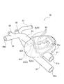
- FIG. 7 It is a figure which shows another example (3rd Embodiment) of the TAVI model which is one of the heart models based on this invention, (a) is a general view in the state equipped with an aortic valve, (b) is an aortic valve The partial view of the opening of the aorta and an aortic valve in the state which removed.
- (a) is an enlarged view of the removed aortic valve
- (b) is a perspective view looking at the inside of the TAVI model from the opening of the inflow tube, which is an enlarged view near the opening of the aorta.
- FIG. 18 is a perspective view of an extension member usable with the TAVI models of the second and third embodiments.
- BRIEF DESCRIPTION OF THE DRAWINGS The whole schematic which shows one use form of the container for catheter simulators which concerns on this invention.
- FIG. 1 is a view showing an embodiment of a catheter simulator container according to the present invention.
- the catheter simulator container will be described with reference to FIG.
- the catheter simulator container 10 of the present embodiment is configured as a container that defines a container 10 a for containing a liquid (not shown) such as water or electrolyzed water by the four side walls 11 to 14 and the bottom surface 15.
- a liquid such as water or electrolyzed water by the four side walls 11 to 14 and the bottom surface 15.
- a heart model four-chamber model in FIG. 3 (right heart model 20 in the present embodiment), a coronary artery model 30 in FIG. 4, and a TAVI model in FIG. 5) 40, connection portions 11a and 11c connectable to and held by the TAVI model 80 of FIG. 6 or the TAVI model 100 of FIG.
- introduction parts 11d, 12a, 13a for inserting a catheter
- discharge port 11b for discharging the liquid in the storage part 10a to a pulsatile flow generation pump 60 (see FIG. 12; hereinafter referred to as a pump)
- the connection portions 11 a and 11 c also serve as an introduction portion for inserting a catheter from the outside of the container 10.
- the side walls 11 to 14 and the bottom surface 15 are made of a material having a strength capable of stably containing a liquid and a heart model, and the shapes of the side walls 11 to 14 and the bottom surface 15 are short and round. It may be any shape as long as it can stably accommodate the liquid and the heart model, such as a shape having a combination of them.
- the materials of the side walls 11 to 14 and the bottom surface 15 preferably have transparency. The transparency of the side wall and the bottom makes it possible to visually observe the behavior of a heart model installed in the container 10 or a catheter inserted from the outside of the container 10 during simulation. Examples of the material having such strength and transparency are acrylic, polycarbonate, PET, polystyrene and the like.
- the behavior of the catheter can be displayed by installing a camera and displaying it on a monitor or displaying on a monitor etc. with X-ray fluoroscopy. It is possible to carry out simulations that are grasped only on the monitor, and it is also possible to realize a more realistic state. Visual recognition, monitor display confirmation, and use of X-ray imaging can be selected according to the stage and content of training.
- the upper part of the container 10 is open, and an openable and closable lid may be disposed there.
- an openable and closable lid may be disposed there.
- connection portions 11 a and 11 c are formed in a substantially cylindrical shape, penetrate through the side wall 11, and protrude toward the outside of the container 10.
- holding projections 11f and 11g that project to the container housing 10a side in the connection parts 11a and 11c, thereby inserting the end of the heart model and facilitating the heart model. It is possible to connect (hold).
- the supply pipe 63 (refer FIG. 12) of the pump 60 mentioned above is connected to the front-end
- connection portion 11a and the holding projection 11f are formed with communication holes through which the liquid fed from the pump 60 passes, and when the pump 60 is operated, also serve as a liquid inlet from the pump 60.
- connection portion 11c has a function as an introducing portion of the catheter
- connection portion 11c and the holding projection 11g are formed with communication holes through which the catheter is inserted.
- connection portion 11a and the discharge port 11b both have a valve 11V for opening / closing (only the connection portion 11a side is shown).
- the closing valve 11V prevents the liquid in the storage portion 10 a from leaking out of the container 10 by closing the valve 60 when removing the pump 60 from the container 10.
- connection portion 11c An introducing pipe 50 for introducing a catheter operated by a trainee from the outside of the container 10 is connected to the connection portion 11c. Further, the side wall 11 is provided with an introducing portion 11 d for connecting the catheter introducing tube 51.
- the connection portion 11 c and the introduction portion 11 d are formed in a substantially cylindrical shape, penetrate the side wall 11, and protrude outside the container 10.
- the connection portion 11 c and the introduction portion 11 d have a connection mechanism operable on the outside of the container 10.
- the connection mechanism has, for example, a structure capable of fixing and releasing the introduction pipes 50 and 51 when the introduction pipe is inserted and the operation member (nut) 19 is rotated, so that the detachment operation of the introduction pipe can be easily performed. It has become.
- connection portions 11a and 11c and the introduction portion 11d described above do not necessarily have to be disposed on the same side wall.
- An auxiliary plate 16 for reinforcing the strength of the side wall 11 may be adhered to the side wall 11. Reinforcement of strength by the auxiliary plate 16 can reduce the weight of the entire container 10 as compared to the case where the entire side wall 11 is thickened to increase the strength. If the visibility of the passing catheter or the like is reduced by bonding the auxiliary plate 16 to the side wall 11, the thickness of the side wall is increased by increasing only the side of the side wall 11 which needs to be strengthened. Also good. In addition, it is preferable to make the side wall into a flat plate having no unevenness, whereby the refraction of light is eliminated and the visibility inside is improved.
- the side wall 12 is provided with an introducing portion 12 a for connecting a catheter operated by a trainee with an introducing tube 52 for introducing a catheter from the outside of the container 10.
- An introduction portion 13a connected to the introduction pipe 53 is provided.
- These introduction parts 12a and 13a may be arranged on the same side wall.
- the container 10a is filled with a liquid such as water, and the heart model is suspended in the liquid.
- the floating state of the heart model allows the trainee to feel more realistic when operating the catheter. That is, by connecting (holding) the connection portions 11a and 11c provided on the side wall of the container, the cardiac model can be suspended in the liquid.
- a dedicated holder may be installed on the bottom surface of the container and the heart model may be supported from below and held in the liquid without providing a connection on the side wall.
- the element accommodated in the container 10 is only required to be a heart model of the same size as the human heart and a liquid for suspending it, so that the container 10 can be miniaturized.
- the external dimensions of the container 10 in this embodiment are about 20 cm ⁇ 20 cm ⁇ 15 cm, and the amount of liquid (water) that needs to be filled in the container is about 3 L to 6 L.
- the amount of water filled in the container 10a of the container is 6 L or less, even if it is a place where water service is not available, it is possible to carry out a simulation by transporting the water with a tank etc. Spreads.
- the weight of the water-filled container is so light that the trainee can handle it alone, so it is possible to prepare and clear up the simulation without the aid of the assistant.
- the trainee selects an introducing portion (connecting portion) for introducing a catheter from the introducing tubes 50 to 53 depending on the heart model to be used and the contents of simulation.
- the introduction tubes 50 to 53 have a catheter introduction terminal at the tip on the outer side of the container 10, and the introduction terminals have a function to prevent the liquid filled in the introduction tubes 50 to 53 from leaking to the outside (Valve function) and has a structure that allows the trainee to introduce and withdraw a catheter into the introduction tubes 50-53.
- the introduction tube 50 is formed in the coronary artery model 30 (FIG. 4), the TAVI model 40 (FIG. 5), 80 (FIG. 6) or 100 (FIG. 7) through the introduction portion 11c.
- the introductory tube 51 is connected to the inferior vena cava 22 formed in the right heart system model 20 (FIG. 3) through the introductory portion 11 d
- the introductory tube 52 is connected to the coronary artery model 30 through the introductory portion 12a.
- the introduction tube 53 is the superior vena cava 23, which is respectively formed in the right heart system model 20 and the TAVI model 40 through the introduction part 13a. 43 are connected respectively.
- the right heart system model 20 (one embodiment of the four-chamber model), which is one of the heart models according to the present invention, is installed in the storage portion 10a of the container 10.
- the aspect of the case will be described.
- a catheter is made to reach the inside of the heart, it is general to insert the catheter from the right ventricular system (right atrium, right ventricle) connected to a thick blood vessel (the vena cava) leading to the heart. Is formed for simulation of catheter examination inside the heart, surgery and the like.
- the right heart system model 20 of the present embodiment includes a main body 20A that imitates the heart of a human body, and the inside of the main body is the same as the human heart, the right atrium 20A1, the right ventricle 20A2, a left atrium (not shown), and a left ventricle 20A4 are formed.
- the right atrium 20A1 is connected with a vena cava (the lower vena cava 22, the superior vena cava 23), and the right ventricle 20A2 is connected with a pulmonary artery 24.
- the inferior vena cava 22 and the superior vena cava 23 are formed to be long enough to be connected to the catheter introducers 11d and 13a formed in the container 10, since they serve as a catheter introducer.
- the distal end portions of the inferior vena cava 22 and the superior vena cava 23 are open (openings 22a and 23a), and are respectively connected to the introducing portions 11d and 13a formed in the container 10 to introduce a catheter. It becomes a mouth.
- the inferior vena cava 22 leads to a femoral vein traveling in the inguinal region and serves as an introduction path for a catheter introduced from the inguinal region, and the superior vena cava 23 is introduced from an internal jugular vein traveling in the base of the neck It becomes an introduction path of a catheter.
- a blood vessel introducing a catheter is generally a femoral vein, and an internal jugular vein is selected according to a patient's condition etc. Because there are also, it is possible to select two introduction routes according to the actual situation.
- a support 21 connected to the container 10 is formed on the caudal side (end) of the main body 20A of the right heart model 20.
- the support portion 21 does not exist in the human body, in the present embodiment, as shown in FIG. 3, it has a shape in which two substantially rectangular parallelepipeds are connected. Recesses 21a and 21b formed at the end of the support portion 21 are connected to the holding projections 11f and 11g of the connection portions 11a and 11c of the container 10, so that the right heart model 20 can be stably used in the container 10 Have the function of fixing to Thus, the right heart system model 20 is held by the connection portions 11a and 11c so as to float in the liquid filled in the container portion 10a of the container.
- the recess 21a of the support portion 21 may not communicate with the inside of the main body 20A.
- the coronary artery model 30 in the present embodiment will be described.
- the coronary artery model 30 includes a main body 30A that simulates the heart of a human body.
- the heart of the human body comprises a right atrium, a right ventricle, a left atrium, and a left ventricle, but the main body 30A does not have such an internal structure, and the inside is hollow.
- an aorta 32 is provided on the head side of the main body 30A, like the heart of a human body.
- an inflow tube (end) 31 is provided at the apex of the heart formed on the caudal side of the main body 30A.
- the inflow pipe 31 is not present in the human body, but in the present embodiment, it is a path for flowing the liquid (pulsating flow) sent from the pump 60 (see FIG. 12) into the main body 30A.
- the liquid that has flowed into the main body 30A from the inflow pipe 31 passes through the interior of the cavity in a fixed direction, and reaches the aorta 32 with the same flow.
- a large number of coronary arteries 33 having a thin and complicated shape are formed on the surface of the main body 30A, like the human heart.
- the coronary artery 33 branches from the root of the aorta 32 and is provided along the surface of the main body 30A.
- a discharge port 33a is formed in the distal end region of the coronary artery 33, and the liquid flowing into the coronary artery 33 is discharged from the discharge port 33a to the outside (outside of the main body 30A).
- a simulation of a blood vessel connected to the aorta in a human body is provided on the path of the aorta 32 described above.
- a simulated blood vessel as shown in FIG. 4 specifically, a right subclavian artery 34, common carotid arteries 35 and 36 and a left subclavian artery 37 similar to the human body are provided.
- the right subclavian artery 34 is an introduction path of a catheter introduced from an arm, and a catheter operated by a trainee reaches the aorta 32 from the right subclavian artery 34 and further a coronary artery 33 branching from its root. Inserted into Further, in FIG.
- the aorta 32 extending to the back side of the main body 30A reaches the femoral artery traveling in the inguinal region, and serves as an introduction path of a catheter introduced from the inguinal region.
- the opening 31a of the inflow tube 31 is connected to the holding projection 11f of the connection portion 11a, and the opening 32a of the aorta 32 is connected to the holding projection 11g of the connection portion 11c. It is held to float. Then, in this state, the pulsating flow is inflowed from the external pump through the inflow pipe 31.
- the TAVI model 40 in the present embodiment includes a main body 40A that imitates the human heart, and the inside of the main body 40A is a right atrium 40A1, a right ventricle 40A2, a left atrium (not shown), a left ventricle 40A4 is formed. Similar to the heart of the human body, the right atrium 40A1 is connected with a vena cava (the lower vena cava 42 and the upper vena cava 43), the right ventricle 20A2 is connected with a pulmonary artery 44, and the left ventricle 40A2 is connected with an aorta 45. .
- the aorta may be equipped with the left subclavian artery 37 and the common carotid arteries 35 and 36 as in the coronary artery model 30 shown in FIG. Moreover, although the aortic valve is arrange
- the aorta 45, the inferior vena cava 42, the right subclavian artery 46, and the superior vena cava 43 serve as a catheter introducing path, and therefore, the connection portion 11c formed in the container 10 and the catheter introducing portions 11d, 12a, 13a.
- connection part 11c and the introduction parts 11d, 12a and 13a are connected to become an introduction port of a catheter.
- an inflow tube 41 is provided at the apex of the heart formed on the caudal side of the heart body.
- the fluid (pulsating flow) sent from the pump 60 (see FIG. 12) is made to flow into the main body in the same manner as the coronary artery model 30 described above. It becomes a route.
- the fluid that has flowed into the main body from the inflow tube 41 mainly flows from the left ventricle 40A4 to the aorta 45, partially from the coronary artery, and from the aorta to the common carotid artery, subclavian artery, and descending aorta.
- the coronary artery 33, the common carotid arteries 35 and 36, and the subclavian arteries 34 and 37 may be provided.
- the coronary artery branch (inlet) is located on the head side of the aortic valve.
- the aorta 45 and the inferior vena cava 42 respectively extend to the femoral artery and femoral vein which run in the inguinal region, and serve as a catheter introduction path introduced from the inguinal region.
- the superior vena cava 43 serves as an introduction path for a catheter introduced from an internal jugular vein that travels at the base of the neck.
- the catheter introduction site is generally the femoral artery or apex, but depending on the condition of the patient, the subclavian artery, As femoral veins and internal jugular veins may be selected, it is possible to add an introduction route according to the actual situation.
- the inflow tube 41 will be simultaneously used as a catheter insertion path as described in detail below, but at this time the catheter is inserted between the pump and the opening 41a.
- a catheter introducer may be newly provided or a bifurcated tube may be connected so that it can be performed.
- FIG. 6 is a view for explaining another embodiment of the TAVI model (TAVI model 80 which is the second embodiment).
- the TAVI model 80 is a cavity in which a right atrium, a right ventricle, a left atrium, and a left ventricle are not formed inside a main body 80A that simulates the heart of a human body.
- a main body 80A that simulates the heart of a human body.
- the catheter moves only inside the left ventricle to the aorta and is not a simulation moving inside the other right atrium, right ventricle, and left atrium
- the inside of the main body 80A is limited to these, namely, Even if the atrial septum, ventricular septum, tricuspid valve, and mitral valve are not formed, it does not become a major obstacle. It is possible to simulate the united cavity as the left ventricle.
- an aorta 82 is provided on the head side of the main body 80A.
- the aorta 82 projects from the head side of the main body 80A into the inside of the main body 80A, and an aortic valve 82A is formed at the tip end thereof like the human body.
- the aortic valve 82A is located at the boundary between the aorta 82 and the left ventricle in the human body, but in the present embodiment the left ventricle is not formed, so the aorta 82 is up to the position assumed when the left ventricle is present.
- the aortic valve 82A is formed at its tip.
- the aortic valve 82A has three leaflets, a right coronary apex 82A1, a left coronary apex 82A2, and a non-coronary apex 82A3, as in the human body.
- the aortic valve 82A has a shape in which the three valve leaflets are connected at the root like a petal, and each of the valve leaflets 82A1, 82A2, 82A3 has a rounded petal shape.
- three different color dots red, yellow, green
- each valve leaflet is associated with color one to one. It has become. These dots serve as marks for introducing and simulating a catheter under visual observation.
- radiopaque material for these points, it can be used as a so-called opaque marker under X-ray fluoroscopy as a mark at the time of simulation.
- shape of a marker should just be recognized as a mark, and is not limited to a point mark like a figure.
- the same process may be applied to the annulus part other than the bottom part of each valve leaflet to make a mark.
- an inflow tube (end portion) 81 is provided at the apex of the heart formed on the caudal side of the main body 80A.
- the inflow pipe 81 is not present in the human body, but in the present embodiment, it is a path for flowing the liquid (pulsating flow) sent from the pump 60 into the main body 80A.
- a coronary artery 83 is formed on the surface of the main body 80A, and simulation similar to that of the coronary artery model 30 described above can also be performed.
- the coronary artery 83 may not be formed because it is not essential for simulation of transcatheter aortic valve replacement using a TAVI model, but it is desirable that it be present.
- a coronary artery occlusion may occur as a complication, and in the operation, an angiogram of the coronary artery may be performed to confirm the occlusion state.
- a blood vessel mimic connected to the aorta in a human body is provided on the above-described path of the aorta 82.
- a simulated blood vessel as shown in FIG. 6, specifically, a right subclavian artery 84, common carotid arteries 85 and 86, and a left subclavian artery 87 similar to the human body are provided.
- an aorta 82 extending to the back side of the main body 80A extends to the femoral artery traveling in the inguinal region, and serves as an introduction path of a catheter introduced from the inguinal region.
- the opening 81a of the inflow tube 81 serves as an inlet for the pulsatile flow from the pump 60 as described above, and also serves as a catheter inlet in the apex approach.
- the indwelling stent valve is formed by making the diameter of the openings 41a and 81a of the inflow tube larger than that of the coronary artery model (opening 31a of the inflow tube of FIG. 4). It can be easily taken out from the apical side.
- FIGS. 7-8 are diagrams for explaining another embodiment of the TAVI model (the third embodiment, the TAVI model 100).
- the right atrium, the right ventricle, the left atrium, and the left ventricle are not formed inside the main body 100A that imitates the human heart, like the above-described TAVI model 80. , Is hollow.
- the inside of the main body 100A hollow there is an advantage that the pulsating flow flowing from the pump 60 makes the main body 100A easy to beat.
- the catheter moves only inside the left ventricle to the aorta and is not a simulation moving inside the other right atrium, right ventricle, and left atrium, the inside of the main body 100A is limited to these, ie, Even if the atrial septum, ventricular septum, tricuspid valve, and mitral valve are not formed, it does not become a major obstacle. It is possible to simulate the united cavity as the left ventricle.
- an aorta 102 is provided on the head side of the main body 100A.
- the aorta 102 protrudes from the head side of the main body 100A into the inside of the main body 100A, and the tip thereof is an opening 102b.
- the removable aortic valve 110 is attached to the opening 102b.
- the aortic valve 110 is located at the boundary between the aorta 102 and the left ventricle in the human body, but in the present embodiment the left ventricle is not formed, so the aorta 102 reaches the position assumed when the left ventricle is present.
- the aortic valve 110 is configured to be mounted at its tip.
- the aortic valve In the human body, the aortic valve is integrally connected to the tip of the aorta as in the TAVI model 80 of the second embodiment, but in the TAVI model 100 of the present embodiment, the aortic valve 110 is other than that And are separately formed and are detachable. For this reason, if the aortic valve 100 is prepared in accordance with various cases and patient-specific situations, simulations can be easily performed on various aortic valves by replacing only the aortic valve 100. Become. In the case of the TAVI model 80, it is necessary to form a plurality of whole TAVI models in accordance with the aortic valve, and in the case of installation, it is necessary to replace the whole model. Also, at the time of installation, only the aortic valve may be detached and replaced. It is efficient in many points such as manufacturing cost, work efficiency, storage space and so on.
- aortic valve 110 detachable, as will be described later, it becomes possible to easily remove the stained valve (a stent with a prosthetic valve) indwelling in the aortic valve 110 at the end of the simulation.
- the aorta 102 and the aortic valve 110 attached to and removed from the aorta will be described with reference to FIGS. 7 (b) to 9.
- the aortic valve 110 includes a valve leaflet 110A including respective leaflets of a right coronary leaflet 110A1, a left coronary leaflet 110A2 and a non-coronal leaflet 110A3 that simulate the aortic valve of a human body.
- the valve-shaped left ventricular outflow passage 112 is connected to the annular annulus 114 and the annulus 114 at the root of the valve leaflet 110A, where the valve leaflets are connected like a petal.
- the aortic valve 110 is inserted into the interior of the heart body 100A from the opening 101a of the inflow tube with the valve tip 110A forward, and is inserted into the opening 102b of the aorta. After insertion, the aortic valve 110 is fixed and attached to the tip of the aorta 102 by connecting the annulus 114 with the peripheral edge 102 c of the opening 102 b.
- the annulus portion 114 and the peripheral portion 102c of the opening 102b are connected by rotating and overlapping the projection 114B of the inner ring 120 and the projection 102B of the outer ring 130 bonded to each other.
- the structure is For this reason, at the time of insertion, it is necessary to insert so that the protrusion 114B on the annulus 114 side does not contact the protrusion 102B formed on the inner inner surface on the aorta 102 side.
- a mark black circle in the drawing
- the aortic valve 110 can be inserted in the correct orientation by inserting the protuberance 114B so that the protuberance 114B is not in contact.
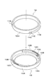
- An inner ring 120 is fixed to the outer periphery of the valve ring portion 114, and an outer ring 130 is fixed to the inner inner peripheral surface of the peripheral portion 102c of the opening 102b of the aorta 102.
- the inner ring 120 is formed on an annular base 120A and an outer periphery of the base 120A, has a protrusion 114B substantially rectangular in cross section, and is adhered and fixed to the outside of the annulus 114 of the aortic valve 110.
- the protrusions 114B are formed at two locations facing each other at a lower part on the outer periphery of the mother body 120A with a central angle of about 80 °, and one end of the protrusions 114B is a periphery as shown in the figure. It has convex part 114D and concave part 114E which were continuously formed in the direction.
- the outer ring 130 has an annular base 130A and a protrusion 102B formed along the inner periphery of the base 130A and having a substantially rectangular cross section, and the inner side of the peripheral part 102c of the opening 102c of the aorta 102 It is fixed to the circumferential surface.
- the protrusions 102B are formed at two upper locations on the inner periphery of the mother body 130A with a central angle of about 90 ° and one of the end portions of the protrusions 102B is shown in the figure. Is provided with a convex portion 102E.
- the outer ring 130 forms a circumferential groove 102e on the inner peripheral surface of the peripheral portion 102c of the opening 102b of the aorta 102, and is embedded in the circumferential groove 102e.
- the outer ring 130 is formed of a hard resin (for example, an epoxy-based or urethane-based hard resin) harder than the material of the aorta 102.
- a stop tool 130B is formed on the inner peripheral surface of the base 130A of the outer ring at a position slightly away from the convex portion 102E in the circumferential direction, and the inner ring 120 is rotated by about 90 ° by this stop tool.
- the protrusion 114B is designed to stop at the position shown.
- the concave portion 114E at the tip of the projection 114 fits into the convex portion 102E of the projection 102B, and the convex portion 114D at the tip of the projection 114 corresponds to the convex portion 102E of the projection 102B and the stopper 130B. It is fixed in the gap of
- the stability of the attached aortic valve can be improved. It is preferable that the connection between the aortic valve 110 and the portion where the aorta 102 is engaged be stable because it is pushed by the catheter to be introduced or receives the pressure of the pulsatile flow from the pump.
- the inner part with respect to the valve ring part 114 so that the positions of the respective valve leaflets (right coronary leaflet 110A1, left coronary leaflet 110A2, non-coronary leaflet 110A3) become similar to the human body.
- the circumferential fixing position of the ring 120 and the circumferential fixing position of the outer ring 130 is design with respect to the inner peripheral surface of the peripheral portion 102c of the opening 102b of the aorta 102.
- the length in the circumferential direction of the protrusions 114B and 102B is a circumferential portion with a central angle of 80 to 90 °, and the number of the protrusions is two at each circumferential position.
- the structure is not particularly limited, and as described above, any structure may be used as long as the protrusion 102B and the protrusion 114B overlap when the aortic valve is attached.
- a slit 102D is provided in a part of the continuous portion of the projection 102B and the base 130A, whereby the projection 102E is formed when the projection 114D contacts the projection 102E (see FIG. 9). Slightly upward). Therefore, the convex portion 114D is configured to rotate even after coming into contact with the convex portion 102E, to displace the end of the protrusion 102B, and to reach the front stopper 130B. This makes it possible to give a sense of moderation at the time of wearing the aorta, and make it possible for the user to grasp the correct wearing position.
- the inner ring 120 or the outer ring 130 is preferably colored.
- a catheter can be introduced visually and can be used as an indication of the position when simulating stent valve placement.
- an X-ray opaque material is used for the colored portion, it becomes a mark when simulating as a so-called opaque marker even under X-ray fluoroscopy.
- a colored or radiopaque material may be used for the annulus portion 114 and the protrusion 114B of the aortic valve 110.
- the annulus of the patient is usually in a calcified condition and X-ray opaque, which is similar to the human body. It is possible to reproduce the situation of Furthermore, a material having radiopacity is applied to the surface of the valve leaflet 110A and the aorta 102, or the material forming the valve ring 110A is rendered radiopaque as in the human body. It is possible to reproduce the situation of calcification in the case of X-ray transmission to make the simulation closer to reality.
- a radiopaque material for example, a material containing hydroxyapatite, a calcium component or a metal component can be mentioned.
- FIG. 10 shows an embodiment in which a support portion (concave and convex that improves the frictional force on the surface) 116 is provided inside the aortic valve 110.
- a support portion concave and convex that improves the frictional force on the surface
- a large number of substantially triangular supports 116 are formed on the inner wall of the annulus 114 of the aortic valve 110 along the inner periphery of the annulus 114.
- the support portion 116 does not exist in the human body, it has an advantage of being able to securely fix and support a stent valve placed by catheter operation.
- the aortic valve of a patient who performs stent valve indwelling treatment has a rough surface due to calcification or the hardness of the valve itself is high, so the stent valve is easily fixed, but a simulation using a heart model In this case, since the surface of the aortic valve is smooth and the hardness of the valve itself is not so high, the deployed stent valve may slip and move along the pulsatile flow. Such a problem can be eliminated by forming the support portion 116 on the inner wall of the aortic valve 110 to improve the surface friction force more than that.
- an inflow tube (end) 101 is provided at the apex of the heart formed on the caudal side of the main body 100A.
- the inflow tube 101 is not present in the human body, but in the present embodiment, it is a path for flowing the liquid (pulsating flow) sent from the pump 60 into the main body 100A.
- the coronary artery 103 is formed on the surface of the main body 100A as in the case of the human heart, and it is also possible to perform the same simulation as the coronary artery model 30 described above.
- the coronary artery 103 may not be formed because it is not essential for simulation of transcatheter aortic valve replacement using a TAVI model, but it is desirable to have one.
- a coronary artery occlusion may occur as a complication, and in the operation, an angiogram of the coronary artery may be performed to confirm the occlusion state. Also, by inserting a guide wire into the coronary artery in advance, it is possible to cope with an occlusion.
- the inner diameter of the inflow tube 101 is preferably larger than the outer diameter of the aortic valve 110.
- the aortic valve 110 preferably has a size resembling a human body, and it is preferable that the aortic valve 110 be larger than the outer diameter of the aortic valve 110 by adjusting the inner diameter of the inflow tube 101.
- a simulation of a blood vessel connected to the aorta in a human body is provided on the path of the aorta 102 described above.
- a simulated blood vessel shown in FIG. 7A specifically, a right subclavian artery 104, common carotid arteries 105 and 106, and a left subclavian artery 107 similar to the human body are provided.
- the aorta 102 extending to the back side of the main body 100A reaches the femoral artery traveling along the inguinal region, and serves as an introduction path of a catheter introduced from the inguinal region.
- a catheter is introduced from the opening 101a of the inflow tube 101.
- the opening 101a serves as an inlet for the pulsatile flow from the pump 60 as described above, and also serves as a catheter inlet in the apex approach.
- the stent valve placed in the aortic valve is formed of a shape memory alloy, expanded at a temperature close to the body temperature (around 30 ° C. to 40 ° C.), and placed.
- a simulation similar to an actual operation is performed by adding a function (a heater or the like installed in the container 10) of a constant temperature bath capable of maintaining the temperature of the container 10 to the same level as human body temperature.
- a function a heater or the like installed in the container 10
- FIG. 11 is a perspective view of the extension member 140.
- the extension member 140 screw-engages with the tubular extension 144 and the extension 144, and the inflow of the holding projection 11f of the container 10 and the TAVI model 80 (100). It has a cylindrical base 142 connected to the tube 81 (101). As shown in the figure, the base portion 142 has irregularities on the outer peripheral surface, and is configured so as not to be easily detached when inserted into the inflow pipe 81 (101).
- An opening 142 c is formed in the inside of the base portion 142 and includes an inner wall having a screw groove formed therethrough.
- a thread is formed on one end 144b of the end of the extension portion 144, and the base portion 142 and the extension portion 144 are connected by rotationally fitting the thread with the thread groove of the opening 142c.
- a through opening 144c is formed in the inside of the extension part 144, and when the base material 142 and the extension part 144 are connected, the opening 144c and the opening 142c communicate with each other.
- the pump 60 is fed out from the pump 60 After passing through the opening 144c through the opening 142c, the pulsatile flow exits the other end 144a of the extension 144 and flows into the heart body 80A (100A) of the TAVI model 80 (100). That is, since the pulsating flow inlet in the heart main body 80A (100A) is moved from the root of the inflow tube 81 (101) to the end 144a by using the extension member 140, the aortic valve 82A (110) is further moved. Get closer to By moving the pulsating flow inlet flowing into the heart model closer to the aortic valve 82A (110), the pulsating flow can be concentrated on the aortic valve 82A (110) without being dissipated.
- the position of the end 144b in the opening 142c can be adjusted by screw fitting so that the position of the pulsating flow inlet (end 124b) flowing into the heart model can be varied. There is.
- the position of the end 124b can be adjusted according to the size of the TAVI model used for simulation, the pressure of the pulsatile flow, etc., and the concentration degree of the pulsatile flow to the aortic valve 82A (110) is optimized. it can.
- FIG. 12 is a view showing a mode of use of the catheter simulator container 10 provided with the bifurcated cock 70.
- a bifurcated tube (bifurcated cock 70)
- the connection portion 11a of the container 10 it is preferable to connect a bifurcated tube (bifurcated cock 70) to the connection portion 11a of the container 10.
- the inflow of the pulsatile flow and the introduction of the catheter can be realized by one opening 41a, 81a or 101a.
- the container 10 is connected to the pump 60 through the supply pipe 63 and the discharge pipe 61, and the bifurcated cock 70 is interposed between the supply pipe 63 and the connection portion 11 a of the container. There is.
- the container 10 may be installed on a fixing stand 200. Depending on the catheter, the guide wire, and other devices that are inserted, the container 10 may be moved by the pressure applied by the trainee at the time of the insertion, and such a situation can be prevented by fixing with the fixing base 200.
- the fixing table 200 may be made of a material (hardened urethane foam or the like) having sufficient strength for holding and fixing the container 10 and having resistance to the liquid to be filled in the container 10.
- the shape is not particularly limited as long as it has stability, but in the case of a plate as shown in FIG. 12, the container 10 can be installed by forming a recess on the plate surface.
- a fixing portion 91 may be formed on the fixing table 200 to hold and fix the introduction path of the catheter. This makes it easier for the trainee to apply pressure when inserting a catheter or the like.
- the heart model installed in the container 10 may be detached from the holding projections 11 f and 11 g of the container 10.
- the connection is reinforced by a fixing ring (not shown) or the heart model is fixed by a holding base (not shown). It can prevent the situation mentioned above.
- the main body 70A of the bifurcated cock 70 is disposed in the inflow tube 71 into which the liquid (pulsating flow) from the pump 60 flows, the introduction path 72 of the catheter, and the introduction path 72 of the catheter, and functions as a one-way valve.
- the inflow tube 71 is disposed to be orthogonal to the introduction path 72, and the opening 71 a of the inflow tube 71 communicates with the inside of the catheter introduction path 72 at the downstream side of the duckbill valve 74. There is. For this reason, the pulsating flow that has passed through the inflow pipe 71 flows into the introduction path 72 through the opening 71a.
- the inflow tube 71 may be disposed in the introduction passage 72 so as to communicate with the inside of the catheter introduction passage 72 on the downstream side of the duckbill valve 74, and is necessarily orthogonal to the introduction passage 72. It does not have to be arranged in
- the one end 72 a of the introduction path 72 is formed with a screw-shaped unevenness, and is connected to the connection portion 11 a of the container 10 by screwing. As a result, the liquid that has flowed into the introduction path 72 from the inflow pipe 71 flows into the TAVI model 40, 80 or 100 in the container 10 through the one end 72a.
- the duckbill valve 74 and the silicone rubber packing 76 are disposed between the end plate 78 and the location where the inflow pipe 71 is disposed orthogonal to the inside of the introduction passage 72.
- the duckbill valve 74 allows insertion of the catheter at the time of opening, and the silicone rubber packing 76 is formed with a hole 76a through which the catheter passes. These function as check valves to prevent the liquid flowing into the introduction path 72 from leaking out of the catheter introduction port 78a, and also play a role of permitting insertion and extraction of the catheter.
- the cross section of the duckbill valve 74 is a bird's beak, when a catheter having a substantially circular cross section is introduced, a gap is generated between the two. At this time, the liquid in the inflow tube 71 leaks from the duckbill valve 74 It will By preventing the leaked liquid from flowing out with the silicone rubber packing 76, the liquid flowing into the introduction path 72 can function as a check valve so as not to leak out from the catheter introduction port 78a.
- the catheter can be brought into close contact with the through hole 76a to eliminate the gap, and the duck bill valve The liquid leaked from 74 can be prevented from flowing out by the silicone rubber packing 76.
- the duckbill valve 74 is automatically closed by the fluid pressure in the catheter introducing passage 72, and the liquid in the catheter introducing tube 72 is shut off by the duckbill valve 74.
- the outflow of fluid from the catheter introducing port 78a to the outside is kept restricted.
- a lid or stopper may be attached to a portion of the catheter introduction port 78a as a mechanism for liquid outflow prevention.
- the bifurcated cock 70 when the insertion part of the catheter and the inlet from the pump 60 coincide, the insertion of the catheter into the heart model is permitted, and the liquid fed from the pump 60 is to the catheter insertion part side.
- Any structure may be used as long as it has a check valve structure that does not leak, and it is possible to appropriately deform, such as using a cross slit valve, for a valve body installed inside and a mechanism for preventing liquid leakage. .
- FIG. 14 shows an example in which a cross slit valve 94 is used for the bifurcated cock 90.
- the main body 90A of the bifurcated cock 90 is disposed in an inflow pipe 91 into which the liquid (pulsating flow) from the pump 60 flows, an introduction path 92 of a catheter, and an introduction path 92 of the catheter, and functions as a one-way valve.
- the inflow pipe 91 is disposed to be orthogonal to the introduction path 92, and the opening 91 a of the inflow pipe 91 communicates with the inside of the catheter introduction path 92 at the downstream side of the cross slit valve 94. ing. For this reason, the pulsating flow that has passed through the inflow pipe 91 flows into the introduction path 92 through the opening 91 a.
- the inflow tube 91 may be disposed in the introduction passage 92 so as to communicate with the inside of the catheter introduction passage 92 on the downstream side of the cross slit valve 94, and is necessarily orthogonal to the introduction passage 92. It does not have to be arranged as such.
- the introduction path 92 At one end 92 a of the introduction path 92, a screw-shaped unevenness is formed, and the connection portion 11 a of the container 10 is connected by screwing. As a result, the liquid that has flowed into the introduction path 92 from the inflow pipe 91 flows into the TAVI model 40, 80 or 100 in the container 10 through the one end 92a.
- a cross slit valve 94 and a valve unit 96 are disposed between the end plate 98 and the location where the inflow pipe 91 is disposed orthogonally.
- the valve unit 96 is internally provided with a slitted silicon plate 96A, and between the silicon plate 96A and the cross slit valve 94 and the end plate 98, as shown in FIG. 14, between the plastic spacer 96B and the plastic spacer 96B.
- a gel 96C is provided to increase the degree of adhesion.
- a hole for allowing insertion and removal of the catheter is formed in each component (silicon plate 96A, plastic spacer 96B, gel 96C) of the valve unit 96.
- the slitted silicon plate 96A has a two-piece structure (the shape of the slit is one each of a horizontal slit and a vertical slit), but the invention is not limited thereto. Several combinations are possible for the number of.
- the above-described heart model (right heart system model 20, coronary artery model 30, TAVI model 40, 80 or 100) is formed of a material having elasticity close to that of an actual human heart, and it is close to reality in simulation. The feel at the time of catheter operation can be obtained.
- the elastic heart body when the pulsatile flow is made to flow from the apex toward the aorta, the elastic heart body repeatedly expands and contracts. Like the heart, it is possible to pump blood (liquid).
- Materials having such elasticity include, for example, PVA (polyvinyl alcohol), polyurethane, epoxy resin, unsaturated polyester, phenol resin, silicon and similar materials, and other thermosetting resins and thermoplastic resins alone. Or what combined two or more etc. are mentioned. This makes it possible to train the catheter operation with a tentacle feel close to that of the human body.
- PVA polyvinyl alcohol
- polyurethane epoxy resin
- unsaturated polyester unsaturated polyester
- phenol resin phenol resin
- silicon and similar materials and other thermosetting resins and thermoplastic resins alone. Or what combined two or more etc. are mentioned. This makes it possible to train the catheter operation with a tentacle feel close to that of the human body.
- the trainee can insert a catheter or a guide wire by using a transparent or translucent material.
- the movement of other devices can be observed directly and visually, and furthermore, it becomes possible to visually recognize the behavior of the infusate injected from the catheter. That is, it is possible to simulate cardiac catheter test and treatment while linking the operation at hand and the movement of the catheter tip.
- the container 10 may be covered with a cover or the like so that the heart model can not be seen, or displayed on a monitor by X-ray fluoroscopy It is also possible to grasp the behavior of the catheter only on the monitor.
- each of the above-described heart models (right heart model 20, coronary artery model 30, TAVI model 40 or 80) be integrally manufactured without having an artificial joint. In this way, it is possible to prevent the occurrence of blood flow not seen in the human body by the joint, and also prevent the visual field from being blocked by the joint at the time of catheter insertion, and unnatural shading under fluoroscopy. Does not occur.
- the catheter simulator according to the present invention can be used as a preparation before actual catheter operation, such as selecting and examining a catheter and various devices that are most suitable for the patient before examination and surgery.
- a heart model is formed by the above-mentioned optical modeling method
- the surface of a heart model is not smooth, but a slight unevenness
- the visible light may be irregularly reflected on the uneven surface, which may lower the visibility.
- the irregular reflection can be reduced and the visibility can be improved by coating the same material on the surface after the formation of the cardiac model and smoothing the uneven surface.
- the TAVI model 100 has the removable aortic valve 110, the aortic valve 110 and the other parts are separately formed, but for the same reason as the other heart models described above, an artificial joint is made as much as possible. It is preferable not to have it but to form by the said optical modeling method, a coating method, etc.
- the inner ring 120 and the outer ring 130 shown in FIG. 9 are formed of epoxy resin, and the other portions are formed of silicon.
- the forming material of the inner ring 120 and the outer ring 130 is not limited to epoxy resin, and may be a material harder than the forming material (silicon in this embodiment) of the other parts of the heart model, such as urethane.
- the right heart system model 20 is installed in the storage portion 10a of the container 10 in a state where the container 10 is filled with a liquid as a preparation.
- the end portions 21a and 21b of the support portion are respectively connected and held in the liquid to the connection portions 11a and 11c of the container so that air does not enter the inside of the main body.
- the distal end portion 22a of the inferior vena cava 22 is connected to the introducing portion 11d of the container, and the distal end portion 23a of the superior vena cava 23 is connected to the introducing portion 13a of the container.
- a catheter is inserted from the internal jugular vein at the base of the neck, and a catheter is inserted from the femoral vein in the inguinal region.
- the catheter is introduced from the superior vena cava 23 through the introduction tube 53.
- the catheter introduced from the superior vena cava 23 enters the right atrium 20A1 and reaches the right ventricle 20A2.
- the catheter is introduced from the inferior vena cava 22 through the introduction tube 51.
- the catheter introduced from the inferior vena cava 22 enters the right atrium 20A1 and reaches the right ventricle 20A2.
- mapping for measuring an electrocardiogram by an electrode attached to the tip of the catheter and detecting a treatment area
- Pressure or cardiac output inside the heart such as a myocardial biopsy such as ablation of the diseased portion electrically ablated with electrodes at the tip of the catheter, myocardial biopsy in which the heart muscle of the suspected disease is picked and collected for pathological examination
- Perform catheter manipulation inside the heart such as right heart catheterization to measure volume.
- a pump 60 for generating a pulsatile flow is connected to the catheter simulation container 10 according to the present invention.
- the tip end of the connecting portion 11 a is obtained by projecting the supply pipe 63 of the pump 60 to the outside of the container 10 so that the flow of liquid supplied from the pump 60 flows in from the connecting portion 11 a of the container 10
- the discharge pipe 61 of the pump 60 is connected to the discharge port 11 b so that the liquid discharged from the container portion 10 a of the container to the pump 60 flows out from the discharge port 11 b to the external pump 60.
- the coronary artery model 30 is placed in the container portion 10a of the container in a state where the container 10 is filled with a liquid as a preparation.
- the inflow tube 31 of the coronary artery model 30 is connected to the holding projection 11 f of the connecting portion 11 a of the container in the liquid so that air does not enter the coronary artery model 30, and the opening of the tip of the aorta 32 32a is connected to the holding projection 11g of the connecting portion 11c of the container, and the opening 34a at the tip of the right subclavian artery 34 is connected to the introducing portion 12a of the container.
- the pump 60 connected to the coronary artery model 30 is intermittently driven to cause a pulsating flow in the liquid.
- the pump 60 has a function of receiving the liquid filled in the container 10 from the discharge port 11 b, delivering the liquid to the introduction pipe 31 at a predetermined pressure, and refluxing the liquid in the container 10.
- a circulation type pump which reciprocates a piston by a drive motor and sends out a liquid.
- the stroke of the piston that is reciprocated it is possible to change the amount of liquid (corresponding to blood pressure) to be delivered in one beat, and by changing the time of one reciprocation of the piston,
- the beat period of the model (corresponding to the heart rate) can be changed.
- a pressure of at most 300 mmHg 20 to 200 times a minute it becomes possible to generate a pulsating flow close to an actual human body. Similar pulsatile flow can also be generated with pumps of variable volume type, such as lobe pumps and tube pumps.
- the pressure for pumping out the liquid from the pump is preferably set to be at most 300 mmHg, because if it exceeds 300 mmHg, it will be different from the actual heart beat of the human body. That is, by adjusting in the range of 0 mmHg to 300 mmHg, it is possible to set a pulsation state according to each patient (each patient case).
- the heart rate When simulating the catheter operation to the actual heart, it is sufficient for the heart rate to be 20 to 200 bpm (beat per minute) in consideration of the beats of the human body that can be assumed, and in the actual heart surgery, the heart rate is 40 As it is considered that most of the operation is performed in the range of ⁇ 100 bpm, the capacity of the pump 60 may be any specification that can deliver 20 to 200 beats per minute to the heart model, taking into consideration the load of the pump In this case, effective simulation can be performed as long as at least 40 to 150 beats per minute can be sent to the heart model.
- the fluid flowing into the coronary artery 33 is discharged to the outside of the heart model 30 from an outlet 33 a provided at the tip of the coronary artery 33, and joins the fluid filled in the container 10.
- the fluid that has flowed into the aorta 32 is drained into the container 20 via the carotid arteries 35 and 36 and the left subclavian artery 37 which are blood vessels provided on the path of the aorta 32, and Join the filled liquid.
- a filter (not shown) for removing foreign matter at the outlet 11b.
- a catheter is inserted from the artery of the arm and a catheter is inserted from the artery of the inguinal region.
- the catheter is introduced from the right subclavian artery 34 via the introduction tube 52.
- the catheter introduced from the right subclavian artery 34 enters the carotid artery 35, passes through the carotid artery 35, and reaches the aorta 32.
- the catheter passes through the aorta 32 and is located at the inlet (corresponding to the coronary artery entrance) of the coronary artery 33 which branches near the junction with the main body 30A.
- the trainee grasps the entrance while visually observing the coronary artery 33 to be inserted (target for treatment) among the left and right coronary arteries, and performs an operation such that the catheter is engaged with the target coronary artery entrance. . That is, the trainee manipulates the catheter while visually observing the coronary artery in need of treatment for the thin and complex coronary artery 33 to engage with the entrance, and subsequently the guide wire required for the treatment is a target site.
- coronography angiography / coronoplasty such as dilation of blood vessel with a balloon catheter and placement of a stent (metal cylinder) .
- the catheter is introduced from the caudal tip (portion corresponding to the inguinal region) of the aorta 32 via the introduction tube 50.
- the catheter passes through the inside of the aorta 32 and reaches the introduction port of the coronary artery 33 provided in the vicinity of the connection between the aorta 32 and the main body 30A.
- the introduction path of the catheter is only on the path of the aorta 32, there are bifurcation points with the carotid arteries 35 and 36 and the right subclavian artery 37 on that path.
- Training can be performed to reach the inlet corresponding to the coronary artery entrance while confirming the positional relationship with the simulated blood vessel and the like.
- the trainee can perform catheterization and surgery training in the same manner as the blood vessels in the arm.
- the pump 60 is connected to the catheter simulation container 10 as in the case of using the coronary artery model 30 described above.
- the tip end of the connecting portion 11 a is obtained by projecting the supply pipe 63 of the pump 60 to the outside of the container 10 so that the flow of liquid supplied from the pump 60 flows in from the connecting portion 11 a of the container 10
- the discharge pipe 61 is connected to the discharge port 11 b so that the liquid discharged from the container portion 10 a of the container to the pump 60 flows out from the discharge port 11 b to the pump 60.
- the TAVI model 40 is installed in the container 10 a of the container in a state where the container 10 is filled with a liquid as a preparation.
- the inflow tube 41 of the TAVI model 40 is connected to the holding projection 11 f of the connection portion 11 a of the container in the liquid so that air does not enter the TAVI model 40 and the tip 45 a of the aorta 45 is
- the opening 42a at the tip of the inferior vena cava 42 is connected to the holding projection 11g of the connecting portion 11c of the container, and the opening 43a at the tip of the upper vena cava 43 is the introducing portion of the container Connect to 13a respectively.
- the pulsating flow flowing from the pump 60 makes it possible to pulse the heart in the same manner as an actual heart.
- the pump 60 is intermittently driven to cause pulsatile flow in the liquid according to the same specifications as in the case of connection with the coronary artery model 30 as described above.
- the fluid delivered from the pump 60 and flowing into the main body of the TAVI model 40 through the inflow tube 41 mainly flows from the left ventricle 40A4 into the aorta 45, partially into the coronary artery and the remainder from the aorta to the common carotid artery And flow to the subclavian artery, descending aorta.
- the drawing simply expresses only the skeletal part of the TAVI model, as shown in FIG. 4, the coronary artery 33, the common carotid arteries 35 and 36, and the subclavian arteries 34 and 37 may be provided.
- the operation training of the catheter is started with the simulated blood flow thus generated.
- simulation can be carried out in the case of insertion from the vein at the base of the neck, in the case of insertion from the apical region, in the case of insertion from the apical region, insertion from the artery and vein mainly in the inguinal region.
- an aortic valve for preventing backflow of blood flow is present, and the aortic valve hardens and the area through which blood can pass is narrowed aortic valve stenosis
- surgery TAVI or TAVR; transcatheter aortic valve replacement
- the folded artificial valve is made to reach the vicinity of the junction of the aorta 45 and the left ventricle 40A2 by a catheter, and then the artificial valve
- the catheter can be trained to expand and secure it in place.
- a catheter equipped with an artificial valve it is possible to expand the valve by operating only a balloon catheter and inflating the balloon at the aortic valve, that is, balloon aortic valvuloplasty (BAV). is there.
- BAV balloon aortic valvuloplasty
- the catheter When simulating an approach from the apex, the catheter is introduced into the left ventricle 40A via the inflow tube 41 and reaches near the aortic valve.
- the catheter When simulating an approach from the subclavian artery, the catheter is introduced into the aorta 45 via the right subclavian artery 46, reaches the vicinity of the aortic valve, and thereafter, almost the same as the approach from the inguinal artery It is possible to carry out a simulation on the flow.
- the catheter when the trainee simulates catheter insertion from the vein at the base of the neck, the catheter is introduced from the superior vena cava 43 through the introduction tube 53 and reaches the right atrium 40A1.
- the catheter when a catheter is introduced from a vein in the inguinal region, the catheter is introduced from the inferior vena cava 42 through the introduction tube 51 and reaches the right atrium 40A1.
- the catheter that has reached the right atrium 40A1 then passes inside the right atrium and enters the right ventricle 40A2 formed ahead of the right atrium 40A1.
- the boundary between the right atrium 40A1 and the right ventricle 40A2 is provided with a tricuspid valve (not shown) for preventing blood regurgitation like the human body.
- the catheter passes through the right ventricle 40A2, it reaches the pulmonary artery 44.
- the boundary between the right ventricle 40A2 and the pulmonary artery 44 is provided with a pulmonary valve (not shown) for preventing blood backflow as in the human body.
- the trainee can simulate the same catheter treatment as that of the aortic valve described above for these tricuspid valve and pulmonary valve.
- the TAVI in the container portion 10a of the container is filled with liquid as a preparation in advance. Install the model 80.
- the inflow tube 81 of the TAVI model 80 is connected to the holding projection 11 f of the connecting portion 11 a of the container in the liquid so that air does not enter the TAVI model 80 and the distal end 82 a of the aorta 82 is It is connected to the holding projection 11g of the connection portion 11c of the container.
- the TAVI model 80 is installed after the base 142 of the extension member is connected to the holding projection 11 f.
- the inflow pipe 81 is connected to the base 142.
- the fluid that is pumped from the pump 60 and flows into the main body of the TAVI model 80 through the inflow pipe 81 passes from the heart body 80A through the aortic valve 82A and flows into the aorta 82.
- a portion of the fluid flowing into the aorta 82 flows into the coronary artery 83, and is discharged from the outlet port 83a provided at the tip of the coronary artery 83 to the outside of the TAVI model 80 to fill the container 10 with the fluid. Join together.
- the fluid flowing along the aorta 82 is discharged into the vessel 10 through the carotid arteries 85 and 86 and the subclavian arteries 84 and 87 which are blood vessels provided on the path of the aorta 82, and the vessel Join the liquid filled in 10.
- the liquid discharged from the tip openings of the coronary artery 83, the carotid arteries 85 and 86, and the subclavian arteries 84 and 87 into the container 10 flows out from the discharge port 11b and circulates to the pump.
- the operation training of the catheter is started with the simulated blood flow thus generated.
- simulation in the case of inserting from the apex can be implemented.
- the inguinal arterial approach requires less strain on the patient's body, but because the route to reach the heart is long, the tortoise of the blood vessel is complicated, or the catheter is used when calcification is seen in the blood vessel Not suitable as an introduction route for In that case, an apical approach in which the heart is pierced with a needle and the catheter introducing port is opened is a powerful means.
- a catheter When a catheter is introduced from the artery in the inguinal region, the catheter is inserted into the caudal tip of the aorta 82 through the introduction tube 50, and then travels on the path of the aorta 82 toward the heart body, and the aortic valve 82A Reach near.
- Surgery (TAVI or TAVR; transcatheter aortic valve replacement) is performed to replace the aortic valve with a prosthetic valve as a treatment for aortic valve stenosis or the like in which the aortic valve hardens and the area through which blood can pass is narrowed.
- the point mark drawn on the bottom of the three valve leaflets of the aortic valve 85A described above can be used as an indication of the position at which the artificial valve is expanded or the balloon is expanded. It is an effective aid for beginners.
- a radiopaque material for these points to make a mark for simulating as a so-called opaque marker even under fluoroscopy.
- injecting a contrast agent the positional relationship between the aortic valve 85A and the catheter is grasped, and the position at which the artificial valve is expanded or the balloon is inflated is confirmed.
- the catheter is introduced to the heart body 80A via the inflow tube 81 and reaches near the aortic valve 82A. From then on, it is possible to simulate in the same flow as the approach from the inguinal artery. In this case, a catheter is introduced from the inflow tube 81 while maintaining the inflow of the pulsatile flow from the inflow tube 81 by the bifurcated cock 70 described above.
- the pump 60 is connected to the catheter simulation container 10, and then the container 10 is filled with the liquid as a preparatory preparation. , Install the TAVI model 100.
- the inflow tube 101 of the TAVI model 100 is connected to the holding projection 11 f of the connecting portion 11 a of the container in liquid so that air does not enter the TAVI model 100 and the leg side of the aorta 102
- the tip end portion 102a is connected to the holding projection 11g of the connection portion 11c of the container.
- the aortic valve 110 is attached to the TAVI model 100 before the installation of the container, the simulation is continuously performed, and when the aortic valve 110 is repeatedly attached and detached, the state where the TAVI model 100 is installed
- the inflow tube 101 is removed from the holding projection 11 f (the base 142 when the extension member 140 is used), and only the aortic valve 110 is opened from the opening 101 a of the inflow tube 101 (in the case where a stent valve indwelling is included).
- the aortic valve 110 may be inserted and inserted through the opening 101a as follows.
- the aortic valve 110 enters the interior of the heart body 100A through the opening 101a of the inflow tube with the valve tip 110A forward with the left ventricular outflow channel 112 held by the user, Is inserted into the opening 102b of After insertion, the aortic valve 110 is fixed and attached to the tip of the aorta 102 by connecting the annulus 114 with the peripheral edge 102 c of the opening 102 b.
- the fixing method is as described above.
- the pulsating flow flowing from the pump 60 makes it possible to pulse the heart in the same manner as an actual heart.
- the pump 60 is intermittently driven to generate a pulsatile flow in the liquid according to the same specification as in the case of connection with the coronary artery model 30, the TAVI model 40 or 80, as described above.
- the fluid that is pumped from the pump 60 and flows into the main body of the TAVI model 100 through the inflow tube 101 passes from the heart body 100A through the aortic valve 110 and flows into the aorta 102.
- the aortic valve 110 is removable but fixed so as not to be desorbed by the flow of fluid from the pump.
- a part of the fluid flowing into the aorta 102 flows into the coronary artery 103, and is discharged from the discharge port 103a provided at the tip of the coronary artery 103 to the outside of the TAVI model 100 and filled in the container 10 Join together.
- the fluid flowing along the aorta 102 is discharged into the vessel 10 through the carotid arteries 105 and 106 and the subclavian arteries 104 and 107 which are blood vessels provided on the path of the aorta 102, and the vessel Join the liquid filled in 10.
- the liquid discharged from the tip openings of the coronary artery 103, the carotid arteries 105 and 106, and the subclavian arteries 104 and 107 into the container 10 flows out from the discharge port 11b and circulates to the pump.
- the operation training of the catheter is started with the simulated blood flow thus generated.
- simulation in the case of inserting from the apex can be implemented.
- the inguinal arterial approach requires less strain on the patient's body, but because the route to reach the heart is long, the tortoise of the blood vessel is complicated, or the catheter is used when calcification is seen in the blood vessel Not suitable as an introduction route for In that case, an apical approach in which the heart is pierced with a needle and the catheter introducing port is opened is a powerful means.
- the catheter When a catheter is introduced from an artery in the inguinal region, the catheter is inserted into the distal end 102b of the aorta 102 through the introduction tube 50, and then travels on the path of the aorta 102 toward the heart body, and the aortic valve 110A Reach near. After reaching the vicinity of the aortic valve 110A, operations of TAVI and BAV can be simulated similarly to the simulation of the TAVI model 80 described above.
- the catheter in the case of simulating an approach from the apex, the catheter is introduced into the heart body 100A via the inflow tube 101 and reaches near the aortic valve 110A. From then on, it is possible to simulate in the same flow as the approach from the inguinal artery. In this case, a catheter is introduced from the inflow tube 101 while maintaining the inflow of the pulsatile flow from the inflow tube 101 by the bifurcated cock 70 described above.
- the artificial valve is expanded or the balloon is expanded by the mark of the aortic valve 110 (mark of the valve annulus) as in the mark of the aortic valve 82A in the TAVI model 80 (point mark of the valve leaflet).
- the positional relationship between the aortic valve 110 and the catheter can be grasped by using a position indicator or injecting a contrast agent.
- the aortic valve 110 in which a stent valve (not shown) is placed can be removed from the TAVI model 100, and the stent valve can be removed from the aortic valve at hand.
- a hand is inserted from the opening 101a of the inflow tube 101, and the left chamber outflow passage portion 112 is held and rotated to release the fitting, and then return inside the inflow tube 101 again. Take it out. Similar work may be performed with forceps, scissors, clips or the like instead of hands.
- connection and use of an external pulsatile flow generation pump can be selected according to the heart model connected to the container, various heart models can be switched, and the use of an external pump can also be selected. It is configured to be able to. This makes it possible to flow a pulsatile flow into the heart model and perform simulation under a realistic heartbeat, for a catheter procedure that is greatly affected by the heartbeat.
- the container 10 can hold the heart model in a floating state by the connection portions 11a and 11c provided on the side wall of the container 10, it is possible to reduce the size and weight without requiring any other dedicated holder or the like. . This expands the choice of where to run the simulation, and also allows the trainee to prepare and clear the simulation alone without the constraints of an assistant.
- the catheter technique such as treatment of coronary artery on the surface of the heart, coronary angiography, coronary angioplasty
- mapping for diseases inside the heart, ablation treatment, catheter operations such as tissue sampling for myocardial biopsy, transcatheter aortic valve replacement, etc.
- the pulsating flow flowing into the heart model makes the pulsating close to reality. Simulation can be performed.
- the various heart models described above can be created based on CT images of actual patients or based on individual cases, it is possible to perform preoperative simulation for each case.
- the heart model can be easily replaced, it is possible to provide an environment for training as a general-purpose model for practice to beginners such as medical students and trainees, but it is also difficult for skilled persons It can be used for training of high cases. That is, based on heart CT data captured in advance, it is possible to model a heart model and simulate it before actual surgery.
- the container for catheter simulators concerning this invention and an example of the embodiment of the various heart models accommodated in the said container were shown, this invention is not limited to said embodiment, This invention Various changes can be made without departing from the scope of the present invention.
- the shape of the container or the bifurcated cock, and the arrangement position of the connection portion and the introduction portion can be appropriately modified.
Landscapes
- Engineering & Computer Science (AREA)
- Physics & Mathematics (AREA)
- General Physics & Mathematics (AREA)
- Health & Medical Sciences (AREA)
- General Health & Medical Sciences (AREA)
- Medical Informatics (AREA)
- Educational Technology (AREA)
- Pure & Applied Mathematics (AREA)
- Computational Mathematics (AREA)
- Medicinal Chemistry (AREA)
- Mathematical Analysis (AREA)
- Mathematical Optimization (AREA)
- Mathematical Physics (AREA)
- Algebra (AREA)
- Business, Economics & Management (AREA)
- Educational Administration (AREA)
- Chemical & Material Sciences (AREA)
- Theoretical Computer Science (AREA)
- Nuclear Medicine, Radiotherapy & Molecular Imaging (AREA)
- Life Sciences & Earth Sciences (AREA)
- Surgery (AREA)
- Radiology & Medical Imaging (AREA)
- Oral & Maxillofacial Surgery (AREA)
- Biomedical Technology (AREA)
- Heart & Thoracic Surgery (AREA)
- Molecular Biology (AREA)
- Animal Behavior & Ethology (AREA)
- Public Health (AREA)
- Veterinary Medicine (AREA)
- Pathology (AREA)
- Instructional Devices (AREA)
- Apparatus For Radiation Diagnosis (AREA)
- External Artificial Organs (AREA)
Abstract
L'invention concerne un récipient (10) pour simulateur de cathéter qui comporte une partie logement (10a) destinée à recevoir un liquide par des parois latérales (11-14) et une surface inférieure (15). Les parois latérales comportent des parties de liaison (11a, 11c) formées sur celles-ci et qui sont capables de retenir n'importe quel modèle de cœur, à savoir un modèle à quatre chambres, un modèle d'artères coronaires ou un modèle TAVI, qui est mis en place lorsque la partie logement (10a) est remplie de liquide ; et des parties d'introduction (11d, 12a, 13a) permettant d'insérer un cathéter depuis l'extérieur du récipient dans des vaisseaux sanguins simulés, qui sont formés d'un seul tenant avec le modèle de cœur.
Priority Applications (5)
| Application Number | Priority Date | Filing Date | Title |
|---|---|---|---|
| JP2017509447A JP6667503B2 (ja) | 2015-11-09 | 2016-03-07 | カテーテル・シミュレーター用容器、及びこの容器内に収容される心臓モデル |
| CN201680019967.1A CN107615360B (zh) | 2015-03-30 | 2016-03-07 | 导管-模拟器用容器、以及收容于该容器内的心脏模型 |
| EP16772106.7A EP3279885B1 (fr) | 2015-03-30 | 2016-03-07 | Récipient pour simulateur de cathéter et modèle de coeur contenu dans ledit récipient |
| US15/718,682 US10937337B2 (en) | 2015-03-30 | 2017-09-28 | Container for catheter simulator and heart model accommodated in said container |
| US17/154,119 US11663929B2 (en) | 2015-03-30 | 2021-01-21 | Heart model |
Applications Claiming Priority (4)
| Application Number | Priority Date | Filing Date | Title |
|---|---|---|---|
| JP2015-068186 | 2015-03-30 | ||
| JP2015068186 | 2015-03-30 | ||
| JP2015219184 | 2015-11-09 | ||
| JP2015-219184 | 2015-11-09 |
Related Child Applications (1)
| Application Number | Title | Priority Date | Filing Date |
|---|---|---|---|
| US15/718,682 Continuation US10937337B2 (en) | 2015-03-30 | 2017-09-28 | Container for catheter simulator and heart model accommodated in said container |
Publications (1)
| Publication Number | Publication Date |
|---|---|
| WO2016158222A1 true WO2016158222A1 (fr) | 2016-10-06 |
Family
ID=57005648
Family Applications (1)
| Application Number | Title | Priority Date | Filing Date |
|---|---|---|---|
| PCT/JP2016/057000 WO2016158222A1 (fr) | 2015-03-30 | 2016-03-07 | Récipient pour simulateur de cathéter et modèle de cœur contenu dans ledit récipient |
Country Status (4)
| Country | Link |
|---|---|
| US (2) | US10937337B2 (fr) |
| EP (1) | EP3279885B1 (fr) |
| CN (1) | CN107615360B (fr) |
| WO (1) | WO2016158222A1 (fr) |
Cited By (7)
| Publication number | Priority date | Publication date | Assignee | Title |
|---|---|---|---|---|
| WO2018079711A1 (fr) * | 2016-10-28 | 2018-05-03 | 国立大学法人大阪大学 | Modèle d'organe pour cathéter et/ou simulateur |
| JP2018072387A (ja) * | 2016-10-24 | 2018-05-10 | 株式会社アールテック | 心臓模型、心臓局部模型、心臓弁模型、冠動脈模型及び大動脈模型 |
| WO2020079779A1 (fr) * | 2018-10-17 | 2020-04-23 | 朝日インテック株式会社 | Dispositif de simulation de corps humain, procédé de commande de dispositif de simulation de corps humain et programme informatique |
| CN113168781A (zh) * | 2018-12-03 | 2021-07-23 | 朝日英达科株式会社 | 血管模型以及脏器模拟器 |
| KR20210097461A (ko) * | 2020-01-30 | 2021-08-09 | (주)시지바이오 | 심장 박동 모사 동적 팬텀 시험기 |
| CN113270018A (zh) * | 2021-05-24 | 2021-08-17 | 哈尔滨工业大学 | 一种用于人工器官测试的体肺血液循环模拟系统 |
| JPWO2023286755A1 (fr) * | 2021-07-15 | 2023-01-19 |
Families Citing this family (24)
| Publication number | Priority date | Publication date | Assignee | Title |
|---|---|---|---|---|
| US11062626B2 (en) * | 2015-05-27 | 2021-07-13 | Atricure, Inc. | Beating heart controller and simulator |
| US11495141B2 (en) * | 2018-03-29 | 2022-11-08 | Cae Healthcare Canada Inc. | Dual channel medical simulator |
| IT201800006287A1 (it) * | 2018-06-13 | 2019-12-13 | Unita' di addestramento/formazione di un operatore ospedaliero per l'esecuzione di trattamenti di elettrofisiologia cardiaca | |
| US11847934B2 (en) * | 2018-06-21 | 2023-12-19 | Beijing Bywave Sensing Technology Co., Ltd. | Blood flow environment simulation device |
| WO2020031474A1 (fr) * | 2018-08-07 | 2020-02-13 | テルモ株式会社 | Simulateur de technique |
| WO2020058760A1 (fr) * | 2018-09-20 | 2020-03-26 | Biomodex S.A.S. | Dispositif de simulation cardiovasculaire spécifique au patient |
| US11682320B2 (en) * | 2018-09-21 | 2023-06-20 | Mentice, Ab | Cardiac simulation device |
| EP3869490A4 (fr) * | 2018-10-17 | 2022-05-18 | Asahi Intecc Co., Ltd. | Appareil de simulation de corps humain |
| US11176849B2 (en) * | 2018-10-29 | 2021-11-16 | The Aga Khan University | Pumping heart simulator |
| EP3893228A4 (fr) * | 2018-12-03 | 2022-06-15 | Asahi Intecc Co., Ltd. | Modèle cardiaque |
| CN109686210B (zh) * | 2019-01-21 | 2024-04-05 | 北京脉之语科技有限公司 | 脉搏模拟装置及脉搏模拟实现方法 |
| US10898329B2 (en) | 2019-01-25 | 2021-01-26 | Edwards Lifesciences Corporation | Testing apparatus for prosthetic device |
| CN109841137B (zh) * | 2019-02-14 | 2023-10-27 | 上海长海医院 | 升主动脉根部腔内治疗训练模型 |
| DE102019116827B4 (de) * | 2019-06-21 | 2023-11-09 | Bernhard Meyer | ÜBUNGSVORRICHTUNG ZUR SIMULATION EINES DURCHSTRÖMTEN GEFÄßBETTES UND DAZUGEHÖRIGES VERFAHREN |
| RU193663U1 (ru) * | 2019-07-09 | 2019-11-11 | Александр Викторович Никольский | Учебная анатомическая модель сердца человека |
| CN114144822A (zh) * | 2019-08-02 | 2022-03-04 | 株式会社发索科技 | 二尖瓣模型及固定夹具 |
| WO2021026537A1 (fr) * | 2019-08-08 | 2021-02-11 | Vascular Simulations, Inc. | Dispositif de simulation cardiaque |
| CN110974317A (zh) * | 2019-11-25 | 2020-04-10 | 西安马克医疗科技有限公司 | 经导管二尖瓣疾病治疗手术的3d模型体外模拟装置及系统 |
| CN110974318A (zh) * | 2019-11-25 | 2020-04-10 | 西安马克医疗科技有限公司 | 一种经导管主动脉瓣置换术的体外模拟装置与模拟系统 |
| EP4120224A4 (fr) * | 2020-03-11 | 2024-03-27 | Univ Osaka | Simulateur de cathéter et modèle cardiaque pour simulateur de cathéter |
| CN112837594B (zh) * | 2021-02-08 | 2024-05-03 | 中国人民解放军联勤保障部队第九〇〇医院 | 一种能调节跳动节律的心律演示模型 |
| EP4352739A2 (fr) * | 2021-06-07 | 2024-04-17 | Dasisimulations, Llc | Systèmes et procédés pour optimiser des interventions médicales à l'aide de modèles prédictifs |
| CN114209428B (zh) * | 2021-12-27 | 2024-01-30 | 湘南学院 | 一种模拟急性肾损伤的装置 |
| CN115394162B (zh) * | 2022-08-19 | 2023-07-25 | 北京旭合瑞科技有限公司 | 一种模拟临床情景的显微手术训练操作台 |
Citations (4)
| Publication number | Priority date | Publication date | Assignee | Title |
|---|---|---|---|---|
| JP2008237304A (ja) * | 2007-03-26 | 2008-10-09 | Univ Kansai Medical | 心血管系シミュレーションモデル |
| JP2013158372A (ja) * | 2012-02-01 | 2013-08-19 | Toshiba Corp | 医用画像処理装置、医用画像処理方法及びx線撮影装置 |
| JP2013200368A (ja) * | 2012-03-23 | 2013-10-03 | Terumo Corp | トレーニング装置 |
| JP2013213986A (ja) * | 2012-04-03 | 2013-10-17 | Toshio Nakanishi | 先天性心疾患治療のためのトレーニング装置およびそれを用いたトレーニング方法 |
Family Cites Families (8)
| Publication number | Priority date | Publication date | Assignee | Title |
|---|---|---|---|---|
| EP1536395A4 (fr) * | 2002-05-10 | 2012-08-01 | Nagoya Ind Science Res Inst | Modele tridimensionnel |
| CN2607635Y (zh) * | 2002-12-20 | 2004-03-24 | 张导华 | 一种人体心脏模型 |
| DE202004006035U1 (de) * | 2004-04-14 | 2004-08-26 | Hutzenlaub, Jens | Anatomisches Lehr- und Übungsmodell |
| CN2710073Y (zh) * | 2004-07-29 | 2005-07-13 | 代义壮 | 综合性动静脉血管疾病造影及介入治疗训练模拟装置 |
| US20130288218A1 (en) * | 2012-04-27 | 2013-10-31 | Medtronic Cryocath Lp | Cardiac model for simulating medical procedures |
| US20140087344A1 (en) * | 2012-09-24 | 2014-03-27 | Adventist Health System/Sunbelt, Inc. | Apparatus and Method for Demonstrating Surgical Procedures Using Dead Body Organs |
| JP6317885B2 (ja) * | 2013-03-01 | 2018-04-25 | テルモ株式会社 | トレーニング装置 |
| EP3223263B1 (fr) | 2014-11-10 | 2021-01-06 | Osaka University | Simulateur de cathéter et procédé d'imagerie pour un simulateur de cathéter |
-
2016
- 2016-03-07 EP EP16772106.7A patent/EP3279885B1/fr active Active
- 2016-03-07 WO PCT/JP2016/057000 patent/WO2016158222A1/fr active Application Filing
- 2016-03-07 CN CN201680019967.1A patent/CN107615360B/zh active Active
-
2017
- 2017-09-28 US US15/718,682 patent/US10937337B2/en active Active
-
2021
- 2021-01-21 US US17/154,119 patent/US11663929B2/en active Active
Patent Citations (4)
| Publication number | Priority date | Publication date | Assignee | Title |
|---|---|---|---|---|
| JP2008237304A (ja) * | 2007-03-26 | 2008-10-09 | Univ Kansai Medical | 心血管系シミュレーションモデル |
| JP2013158372A (ja) * | 2012-02-01 | 2013-08-19 | Toshiba Corp | 医用画像処理装置、医用画像処理方法及びx線撮影装置 |
| JP2013200368A (ja) * | 2012-03-23 | 2013-10-03 | Terumo Corp | トレーニング装置 |
| JP2013213986A (ja) * | 2012-04-03 | 2013-10-17 | Toshio Nakanishi | 先天性心疾患治療のためのトレーニング装置およびそれを用いたトレーニング方法 |
Non-Patent Citations (1)
| Title |
|---|
| See also references of EP3279885A4 * |
Cited By (14)
| Publication number | Priority date | Publication date | Assignee | Title |
|---|---|---|---|---|
| JP2018072387A (ja) * | 2016-10-24 | 2018-05-10 | 株式会社アールテック | 心臓模型、心臓局部模型、心臓弁模型、冠動脈模型及び大動脈模型 |
| US11195436B2 (en) | 2016-10-28 | 2021-12-07 | Osaka University | Organ model for catheter simulator |
| CN109716419A (zh) * | 2016-10-28 | 2019-05-03 | 国立大学法人大阪大学 | 导管-模拟器用内脏器官模型 |
| JPWO2018079711A1 (ja) * | 2016-10-28 | 2019-10-10 | 国立大学法人大阪大学 | カテーテル・シミュレーター用臓器モデル |
| WO2018079711A1 (fr) * | 2016-10-28 | 2018-05-03 | 国立大学法人大阪大学 | Modèle d'organe pour cathéter et/ou simulateur |
| JP7054112B2 (ja) | 2016-10-28 | 2022-04-13 | 国立大学法人大阪大学 | カテーテル・シミュレーター用臓器モデル |
| WO2020079779A1 (fr) * | 2018-10-17 | 2020-04-23 | 朝日インテック株式会社 | Dispositif de simulation de corps humain, procédé de commande de dispositif de simulation de corps humain et programme informatique |
| CN113168781A (zh) * | 2018-12-03 | 2021-07-23 | 朝日英达科株式会社 | 血管模型以及脏器模拟器 |
| KR20210097461A (ko) * | 2020-01-30 | 2021-08-09 | (주)시지바이오 | 심장 박동 모사 동적 팬텀 시험기 |
| KR102376781B1 (ko) | 2020-01-30 | 2022-03-21 | (주)시지바이오 | 심장 박동 모사 동적 팬텀 시험기 |
| CN113270018A (zh) * | 2021-05-24 | 2021-08-17 | 哈尔滨工业大学 | 一种用于人工器官测试的体肺血液循环模拟系统 |
| JPWO2023286755A1 (fr) * | 2021-07-15 | 2023-01-19 | ||
| WO2023286755A1 (fr) * | 2021-07-15 | 2023-01-19 | 国立大学法人大阪大学 | Simulateur de cathéter et modèle cardiaque pour un simulateur de cathéter |
| JP7401867B2 (ja) | 2021-07-15 | 2023-12-20 | 国立大学法人大阪大学 | カテーテル・シミュレータ、及び、カテーテル・シミュレータ用の心臓モデル |
Also Published As
| Publication number | Publication date |
|---|---|
| CN107615360B (zh) | 2020-04-21 |
| US20210142695A1 (en) | 2021-05-13 |
| EP3279885B1 (fr) | 2020-01-08 |
| EP3279885A4 (fr) | 2018-09-05 |
| US20180018904A1 (en) | 2018-01-18 |
| US11663929B2 (en) | 2023-05-30 |
| EP3279885A1 (fr) | 2018-02-07 |
| US10937337B2 (en) | 2021-03-02 |
| CN107615360A (zh) | 2018-01-19 |
Similar Documents
| Publication | Publication Date | Title |
|---|---|---|
| WO2016158222A1 (fr) | Récipient pour simulateur de cathéter et modèle de cœur contenu dans ledit récipient | |
| JP6452715B2 (ja) | カテーテル・シミュレーター、及びカテーテル・シミュレーター用造影方法 | |
| US10672513B2 (en) | Physiologic simulator system | |
| JP7054112B2 (ja) | カテーテル・シミュレーター用臓器モデル | |
| US8021161B2 (en) | Simulated heart valve root for training and testing | |
| US20240046819A1 (en) | Catheter simulator and heart model for catheter simulator | |
| JP6667503B2 (ja) | カテーテル・シミュレーター用容器、及びこの容器内に収容される心臓モデル | |
| US20070269784A1 (en) | Simulated heat and valve root for training and testing | |
| CN112233488A (zh) | 模块化心脏脉动模拟装置和生物仿真食道超声模拟系统 | |
| JP7251746B2 (ja) | カテーテル・シミュレータ、及び、カテーテル・シミュレータ用の心臓モデル | |
| CA2649487A1 (fr) | Valvule cardiaque artificielle utilisee a des fins de formation et de test | |
| HU231198B1 (hu) | Körkés pozícionálását elősegítő héj, eljárás a héj előállítására, eljárás a héj alkalmazására műtéti eljárás szimulációja során | |
| CN213424272U (zh) | 模块化心脏脉动模拟装置和生物仿真食道超声模拟系统 | |
| WO2023223675A1 (fr) | Modèle d'organe pour dispositif médical | |
| Geurtsen | Optimizing the design of a dynamic cardiac phantom for MR guided intervention training |
Legal Events
| Date | Code | Title | Description |
|---|---|---|---|
| 121 | Ep: the epo has been informed by wipo that ep was designated in this application |
Ref document number: 16772106 Country of ref document: EP Kind code of ref document: A1 |
|
| ENP | Entry into the national phase |
Ref document number: 2017509447 Country of ref document: JP Kind code of ref document: A |
|
| REEP | Request for entry into the european phase |
Ref document number: 2016772106 Country of ref document: EP |
|
| NENP | Non-entry into the national phase |
Ref country code: DE |