WO2016158008A1 - コンクリート補強用成形体、その製造方法、コンクリート補強用成形体の包装構造及び繊維補強コンクリートの混練方法 - Google Patents
コンクリート補強用成形体、その製造方法、コンクリート補強用成形体の包装構造及び繊維補強コンクリートの混練方法 Download PDFInfo
- Publication number
- WO2016158008A1 WO2016158008A1 PCT/JP2016/053547 JP2016053547W WO2016158008A1 WO 2016158008 A1 WO2016158008 A1 WO 2016158008A1 JP 2016053547 W JP2016053547 W JP 2016053547W WO 2016158008 A1 WO2016158008 A1 WO 2016158008A1
- Authority
- WO
- WIPO (PCT)
- Prior art keywords
- molded body
- concrete
- concrete reinforcing
- fiber
- thickness
- Prior art date
Links
Images


Classifications
-
- B—PERFORMING OPERATIONS; TRANSPORTING
- B28—WORKING CEMENT, CLAY, OR STONE
- B28C—PREPARING CLAY; PRODUCING MIXTURES CONTAINING CLAY OR CEMENTITIOUS MATERIAL, e.g. PLASTER
- B28C5/00—Apparatus or methods for producing mixtures of cement with other substances, e.g. slurries, mortars, porous or fibrous compositions
- B28C5/40—Mixing specially adapted for preparing mixtures containing fibres
- B28C5/402—Methods
-
- B—PERFORMING OPERATIONS; TRANSPORTING
- B28—WORKING CEMENT, CLAY, OR STONE
- B28B—SHAPING CLAY OR OTHER CERAMIC COMPOSITIONS; SHAPING SLAG; SHAPING MIXTURES CONTAINING CEMENTITIOUS MATERIAL, e.g. PLASTER
- B28B1/00—Producing shaped prefabricated articles from the material
- B28B1/52—Producing shaped prefabricated articles from the material specially adapted for producing articles from mixtures containing fibres, e.g. asbestos cement
- B28B1/523—Producing shaped prefabricated articles from the material specially adapted for producing articles from mixtures containing fibres, e.g. asbestos cement containing metal fibres
-
- B—PERFORMING OPERATIONS; TRANSPORTING
- B28—WORKING CEMENT, CLAY, OR STONE
- B28C—PREPARING CLAY; PRODUCING MIXTURES CONTAINING CLAY OR CEMENTITIOUS MATERIAL, e.g. PLASTER
- B28C7/00—Controlling the operation of apparatus for producing mixtures of clay or cement with other substances; Supplying or proportioning the ingredients for mixing clay or cement with other substances; Discharging the mixture
- B28C7/04—Supplying or proportioning the ingredients
- B28C7/06—Supplying the solid ingredients, e.g. by means of endless conveyors or jigging conveyors
-
- C—CHEMISTRY; METALLURGY
- C04—CEMENTS; CONCRETE; ARTIFICIAL STONE; CERAMICS; REFRACTORIES
- C04B—LIME, MAGNESIA; SLAG; CEMENTS; COMPOSITIONS THEREOF, e.g. MORTARS, CONCRETE OR LIKE BUILDING MATERIALS; ARTIFICIAL STONE; CERAMICS; REFRACTORIES; TREATMENT OF NATURAL STONE
- C04B14/00—Use of inorganic materials as fillers, e.g. pigments, for mortars, concrete or artificial stone; Treatment of inorganic materials specially adapted to enhance their filling properties in mortars, concrete or artificial stone
- C04B14/38—Fibrous materials; Whiskers
- C04B14/48—Metal
-
- C—CHEMISTRY; METALLURGY
- C04—CEMENTS; CONCRETE; ARTIFICIAL STONE; CERAMICS; REFRACTORIES
- C04B—LIME, MAGNESIA; SLAG; CEMENTS; COMPOSITIONS THEREOF, e.g. MORTARS, CONCRETE OR LIKE BUILDING MATERIALS; ARTIFICIAL STONE; CERAMICS; REFRACTORIES; TREATMENT OF NATURAL STONE
- C04B20/00—Use of materials as fillers for mortars, concrete or artificial stone according to more than one of groups C04B14/00 - C04B18/00 and characterised by shape or grain distribution; Treatment of materials according to more than one of the groups C04B14/00 - C04B18/00 specially adapted to enhance their filling properties in mortars, concrete or artificial stone; Expanding or defibrillating materials
-
- E—FIXED CONSTRUCTIONS
- E04—BUILDING
- E04C—STRUCTURAL ELEMENTS; BUILDING MATERIALS
- E04C5/00—Reinforcing elements, e.g. for concrete; Auxiliary elements therefor
- E04C5/01—Reinforcing elements of metal, e.g. with non-structural coatings
- E04C5/012—Discrete reinforcing elements, e.g. fibres
-
- E—FIXED CONSTRUCTIONS
- E04—BUILDING
- E04C—STRUCTURAL ELEMENTS; BUILDING MATERIALS
- E04C5/00—Reinforcing elements, e.g. for concrete; Auxiliary elements therefor
- E04C5/07—Reinforcing elements of material other than metal, e.g. of glass, of plastics, or not exclusively made of metal
- E04C5/073—Discrete reinforcing elements, e.g. fibres
- E04C5/076—Specially adapted packagings therefor, e.g. for dosing
Definitions
- the present invention relates to a concrete reinforcing fiber molded body, a manufacturing method thereof, a packaging structure of a concrete reinforcing molded body, and a method of kneading fiber reinforced concrete.
- concrete reinforcing fibers metal fibers, resin fibers, inorganic fibers, etc.
- the concrete reinforcing fiber has a diameter of a few millimeters of comma and a length of several tens of millimeters (see Patent Documents 2 and 3).
- the concrete reinforcing fiber When the concrete reinforcing fiber is stored in a drum can or the like and put into a concrete kneader, the concrete reinforcing fiber is taken out from the drum can, passed through a sieve, and then put into the kneader.
- an object of the present invention is to eliminate on-site sieving work of the concrete reinforcing fiber.
- the present invention is a concrete reinforcing molded body that includes a concrete reinforcing fiber and has a plate shape.
- the present invention is plate-like, entanglement of the fiber for reinforcing the concrete is extremely small, so that when it is put into the kneader, the fiber for reinforcing the fiber may be formed into a fiber ball without kneading it. Absent.
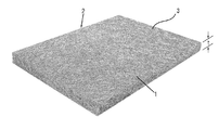
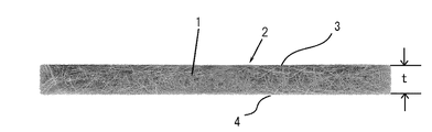
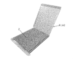
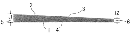
- FIG. 1 It is a perspective view which shows one Embodiment of the molded object for concrete reinforcement which concerns on this invention. It is a side view of the concrete reinforcement molding of the same embodiment. It is the perspective view which accommodated the molded object for the concrete reinforcement in the box. It is a perspective view of the state which opened the lid of the box in which the compact for concrete reinforcement was stored. It is a perspective view for taking out from the box of the concrete reinforcement molding of the embodiment. It is a perspective view of the molded object for concrete reinforcement of other embodiment. It is a side view of the molded object for concrete reinforcement of other embodiment. It is a side view for taking out from the box of the concrete reinforcement molding of other embodiments.
- the concrete reinforcing molded body according to one aspect of the present invention employs a configuration in which a collection of the concrete reinforcing fibers is formed into a plate shape.
- the cross-sectional shape, the diameter in the case of a circular cross section, and the length thereof are arbitrary.
- the diameter 0.3 mm or less
- Length 5 mm or more and 25 mm or less.
- the shape, size, and the like of the concrete reinforcing molded body may be appropriately set by experiment, actual operation, or the like to such an extent that no fiber ball is generated when it is put into a kneader.
- it is a circular shape in a plan view, a vertical shape: 270 mm to 350 mm, a horizontal shape: 310 mm to 400 mm, or a polygonal shape having the same size.
- the concrete reinforcing molded body can be wound in a roll shape, and the roll-shaped reinforcing fiber molded body can be held in a roll shape by being accommodated in a cylinder or by wrapping a sheet with a winding string.
- the reinforcing fibers aligned in the XY axis direction may move.
- the size of the inlet in the kneader is also a restriction on the size of the inlet in the kneader.
- the viscosity of the concrete is low (soft), fiber balls may be generated due to low action (shearing force, etc.) of separating the concrete reinforcing fibers.
- the thickness is preferably 3 mm or more and 45 mm or less.
- the concrete reinforcing fiber is preferably a steel material.
- the compressive strength and bending strength of the concrete to which the fiber is added can be further increased.
- the concrete reinforcing compact preferably has a density of 300 g / cm 3 or more and 1000 g / cm 3 or less.
- the density of the concrete reinforcing molded body is less than 300 g / cm 3 , the concrete reinforcing molded body is torn off when put into a kneader, and the workability is lowered. If the density of the concrete reinforcing molded body exceeds 1000 g / cm 3 , the fibers are difficult to disperse in the concrete.
- the concrete reinforcing molded body is connected to the first main surface, a first end surface continuous to the second main surface opposite to the first main surface, the first main surface and the second main surface, and the first main surface.
- the second end surface is opposed to the end surface, and the thickness of the second end surface is smaller than the thickness of the first end surface.
- the frictional resistance between the said concrete reinforcement molded object and a packaging material will become small, and the injection
- the thickness of the second end surface is preferably 5% or more and 50% or less of the thickness of the first end surface.
- the thickness of the second end surface is 50% or less of the thickness of the first end surface, the frictional resistance between the concrete reinforcing molded body and the packaging material is greatly reduced, so that it can be easily put into a kneader. Become. However, when the thickness of the second end face is less than 5% of the thickness of the first end face, the concrete reinforcing molded body is torn off when thrown into the kneader, resulting in poor workability.
- the concrete reinforcing molded body is preferably rectangular in plan view.
- a concrete reinforcing fiber can be dropped into a flat box while passing through a sieve.
- This reinforcing fiber molded body may be put into a concrete kneader as in the conventional case, but at this time, each of the reinforcing fiber molded bodies can be put into the kneader at once.
- the plate-like concrete reinforcing molded body is continuously elongated in one direction (longitudinal direction or short direction of the rectangle in a plan view in FIG. 1) while maintaining its thickness (layer thickness). And cut at an arbitrary position in the continuous direction (length direction of the long object). And it can also be set as the thing of the state rounded (roll-rolled) in the shape of the cut long concrete reinforcement for concrete. If it does in this way, it can throw continuously into a kneader, unwinding this roll-shaped concrete reinforcement molding.
- the number of turns may be 1 or a plurality of 2, 3, 4, or the like.
- This roll-shaped reinforcing fiber molded body can be kept in a roll shape by being housed in a tube or by wrapping a sheet with a winding string.
- FIGS. 3 to 5 cardboard boxes shown in FIGS. 3 to 5 were prepared as the flat box A1 and the flat box A2 as packaging materials.
- the flat box A1 having the inner surface width: 270 mm, the same depth: 310 mm, and the same height: 30 mm, and the inner surface width: 310 mm, the same depth: 310 mm, and the same height: 45 mm as the flat box A2. did.
- the concrete reinforcing fiber 1 having a length of 15 mm was dropped into the flat box A1 and the concrete reinforcing fiber 1 having the length of 22 mm was dropped into the flat box A2 from a container such as the drum can.
- the concrete reinforcing fibers 1 are passed through sieves of meshes 12 (10 mm square holes), dropped while moving horizontally in the sieve alternately in the horizontal direction, and stacked in multiple layers to form the plate-like concrete shown in FIG.
- a reinforcing molded body 2 was formed.
- the thickness t of the concrete reinforcing compact 2 was about 15 mm or 30 mm in the flat box A1 and about 30 mm or 45 mm in the flat box A2.
- the density of the concrete reinforcing compact was 500 g / cm 3 .
- Table 1 shows an experimental example in which these concrete reinforcing molded bodies 2 were used for the production of fiber reinforced concrete called Saxem (registered trademark) shown in Patent Document 1 and the like.
- Saxem registered trademark
- the concrete reinforcing molded body 2 according to the present invention can be smoothly put into a kneader at once as shown in FIG. 5 and fiber balls are hardly generated. it can.
- the side wall a of the flat box A1 and the flat box A2 has an arcuate edge when it is inserted, so that the side wall can be easily opened.
- the concrete reinforcing molded body 2 can be smoothly taken out (injected).
- the fiber reinforced concrete mixed with the concrete reinforcing fiber 1 was satisfactory in terms of mortar flow, slump flow, and flow stop time.
- the concrete reinforcing molded body 2 of the above embodiment was accommodated in a flat rectangular cardboard box. In addition, it can also be rolled.
- the roll-shaped concrete reinforcing molded body 2 can be held in a roll shape by being housed in a tube or by wrapping a sheet with a winding string.
- the manufactured (or manufactured) long object is arbitrarily selected in the length direction. It can also be made into the thing of the state which cut
- both side surfaces in the length direction of the elongated concrete reinforcing molded body 2 can be formed by providing a backing plate as a mold frame in a length within a range where the shape of the reinforcing fiber molded body does not collapse.
- the end surface of the same length can be formed by providing another contact plate as a mold in the orthogonal direction. If the end face is formed with this backing plate, the cutting operation is not necessary.
- the roll-shaped concrete reinforcing molded body 2 can be stored in a cylinder or can be held in a roll shape by binding a sheet with a winding string.
- the said embodiment is an example of a metal fiber as the fiber 1 for concrete reinforcement
- various things such as resin fibers and inorganic fibers, such as carbon, can be used, and the factor used as a fiber ball is the fiber. Since the diameter and length are mainly used, the diameter and length are appropriately set according to various reinforcing fibers so that the fiber balls are not generated by experiments or the like.
- the concrete reinforcing molded body 2 was created in the same manner as in Embodiment 1 except that the thickness of the concrete reinforcing molded body 2 was changed.
- the prepared concrete reinforcing molded body 2 was formed such that the thickness of one end face was thinner than the thickness of the other end face when viewed from the side.
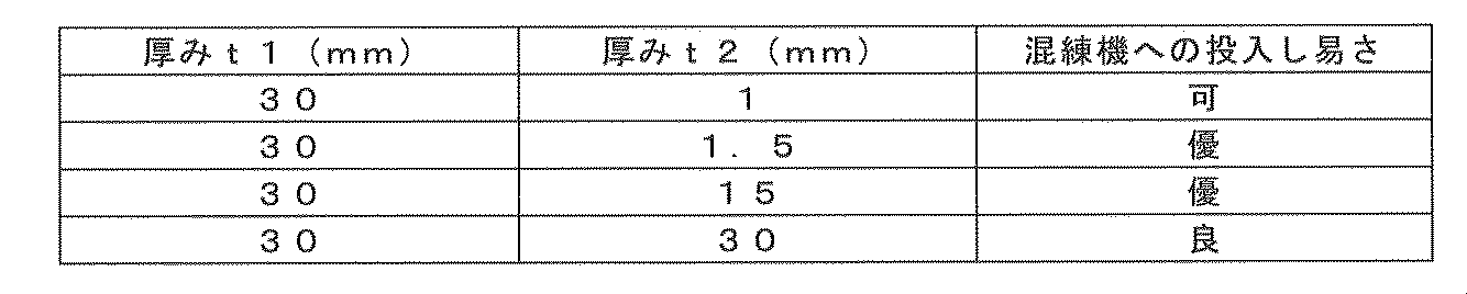
- the concrete reinforcing molded body 2 in which the thickness t1 of the first end face and the thickness t2 of the second end face shown in FIG. 7 were changed was prepared.
- the thickness t1 of the first end face and the thickness t2 of the second end face are shown in Table 2 below.
- the thickness t2 of the second end face is preferably 5% or more and 50% or less of the thickness t1 of the first end face.
Abstract
Description
そのコンクリート補強用繊維は、径がコンマ数ミリ、長さが数十ミリのものである(特許文献2、3参照)。このコンクリート補強用繊維は、ドラム缶等に収納し、コンクリート混練機に投入する際、そのドラム缶からコンクリート補強用繊維を取り出し、篩にかけた後、前記混練機に投入している。
このため、従来では、ドラム缶から混練機にコンクリート補強用繊維を投入する際、篩をかけて投入するようにしている。
本発明の一態様に係るコンクリート補強用成形体は、そのコンクリート補強用繊維の集まりを板状に成形した構成を採用したものである。
<実施形態1>
本発明に係るコンクリート補強用成形体の具体例を説明する。まず、断面円形の径:0.2mmの鋼材の複数本を撚り合わせたスチールコードを、長さ:15mm又は22mmに切断した。これにより、本発明の実施形態に係るコンクリート補強用繊維1を作成した。それらを、ドラム缶等の容器にそれぞれ収納した。

前記コンクリート補強用成形体2の厚みを変更した以外は実施形態1と同様にして前記コンクリート補強用成形体2を作成した。作成した前記コンクリート補強用成形体2は側面から見て一方の端面の厚みを他方の端面の厚みよりも薄くした。具体的には図7に示す第1端面の厚みt1と第2端面の厚みt2を変化させた前記コンクリート補強用成形体2を用意した。第1端面の厚みt1と第2端面の厚みt2を下記表2に示す。
1 コンクリート補強用繊維
2 コンクリート補強用成形体
3 第1主面
4 第2主面
5 第1端面
6 第2端面
t コンクリート補強用成形体の厚み
t1 第1端面の厚み
t2 第2端面の厚み
Claims (11)
- コンクリート補強用繊維を含み、板状であるコンクリート補強用成形体。
- 前記コンクリート補強用繊維は、径:0.3mm以下、長さ:5mm以上25mm以下である請求項1に記載のコンクリート補強用成形体。
- 厚みが、3mm以上45mm以下である請求項1又は請求項2に記載のコンクリート補強用成形体。
- 前記コンクリート補強用繊維は鋼材からなる請求項1~請求項3のいずれか1項に記載のコンクリート補強用成形体。
- 密度が300g/cm3以上1000g/cm3以下である請求項1~請求項4のいずれか1項に記載のコンクリート補強用成形体。
- 第1主面と前記第1主面と反対側の第2主面とに連なる第1端面と、前記第1主面と前記第2主面とに連なり前記第1端面に対向する第2端面を有し、前記第2端面の厚みが前記第1端面の厚みより薄い請求項1~請求項5のいずれか1項に記載のコンクリート補強用成形体。
- 前記第2端面の厚みが前記第1端面の厚みの5%以上50%以下である請求項6に記載のコンクリート補強用成形体。
- 平面視において矩形状である請求項1~請求項7のいずれか1項に記載のコンクリート補強用成形体。
- 請求項1~請求項8の何れか1項に記載のコンクリート補強用成形体の製造方法であって、扁平箱内に、篩をかけた前記コンクリート補強用繊維を落下装填し積層して成形体を製造する補強繊維成形体の製造方法。
- 請求項1~請求項8の何れか1項に記載のコンクリート補強用成形体を扁平箱に収納した補強繊維成形体の包装構造。
- 請求項1~請求項8の何れか1項に記載のコンクリート補強用成形体を、混練機に投入する繊維補強コンクリートの混練方法。
Priority Applications (4)
| Application Number | Priority Date | Filing Date | Title |
|---|---|---|---|
| US15/554,919 US10357897B2 (en) | 2015-04-01 | 2016-02-05 | Concrete-reinforcing shaped body, method of manufacturing the same, structure of packaging concrete-reinforcing shaped body, and method of mixing fiber-reinforced concrete |
| JP2017509343A JP6746871B2 (ja) | 2015-04-01 | 2016-02-05 | コンクリート補強用成形体、その製造方法、及び繊維補強コンクリートの混練方法 |
| EP16771892.3A EP3279169B1 (en) | 2015-04-01 | 2016-02-05 | Concrete reinforcing molded body, method for manufacturing same, packaging structure of concrete reinforcing molded body, and method for kneading fiber reinforced concrete |
| ES16771892T ES2822974T3 (es) | 2015-04-01 | 2016-02-05 | Cuerpo moldeado de refuerzo de hormigón, método para fabricarlo, estructura de empaquetado del cuerpo moldeado de refuerzo de hormigón, y método para amasar hormigón reforzado con fibras |
Applications Claiming Priority (2)
| Application Number | Priority Date | Filing Date | Title |
|---|---|---|---|
| JP2015074795 | 2015-04-01 | ||
| JP2015-074795 | 2015-04-01 |
Publications (1)
| Publication Number | Publication Date |
|---|---|
| WO2016158008A1 true WO2016158008A1 (ja) | 2016-10-06 |
Family
ID=57005544
Family Applications (1)
| Application Number | Title | Priority Date | Filing Date |
|---|---|---|---|
| PCT/JP2016/053547 WO2016158008A1 (ja) | 2015-04-01 | 2016-02-05 | コンクリート補強用成形体、その製造方法、コンクリート補強用成形体の包装構造及び繊維補強コンクリートの混練方法 |
Country Status (5)
| Country | Link |
|---|---|
| US (1) | US10357897B2 (ja) |
| EP (1) | EP3279169B1 (ja) |
| JP (1) | JP6746871B2 (ja) |
| ES (1) | ES2822974T3 (ja) |
| WO (1) | WO2016158008A1 (ja) |
Citations (3)
| Publication number | Priority date | Publication date | Assignee | Title |
|---|---|---|---|---|
| JPS58151362A (ja) * | 1982-03-03 | 1983-09-08 | アイダエンジニアリング株式会社 | コンクリ−ト補強用鋼繊維 |
| EP0557617A1 (en) * | 1992-02-25 | 1993-09-01 | N.V. Bekaert S.A. | Strip of reinforcing fibres |
| JP2011256080A (ja) * | 2010-06-10 | 2011-12-22 | Taiheiyo Cement Corp | セメント質硬化体 |
Family Cites Families (13)
| Publication number | Priority date | Publication date | Assignee | Title |
|---|---|---|---|---|
| NL173433C (ja) * | 1973-04-16 | Bekaert Sa Nv | ||
| US5453310A (en) * | 1992-08-11 | 1995-09-26 | E. Khashoggi Industries | Cementitious materials for use in packaging containers and their methods of manufacture |
| JP3687215B2 (ja) * | 1995-09-25 | 2005-08-24 | 新東工業株式会社 | 耐熱金属繊維焼結体の製造方法 |
| DE19848248C2 (de) | 1998-10-20 | 2001-08-30 | Dyckerhoff Ag | Dünnwandiges Bauteil aus hydraulisch erhärtetem Zementsteinmaterial sowie Verfahren zu seiner Herstellung |
| WO2000049211A1 (en) | 1999-02-19 | 2000-08-24 | W.R. Grace & Co.-Conn. | Packeting fibers for castable compositions |
| JP2001192249A (ja) | 2000-01-07 | 2001-07-17 | Yasuda Kogyo Kk | コンクリート補強用金属繊維およびそれを用いた金属繊維補強コンクリート製品 |
| US6348093B1 (en) * | 2000-04-27 | 2002-02-19 | W. R. Grace & Co. - Conn | Basic-medium-soluble packaging material for use in castable cementitious composites |
| JP2002356353A (ja) | 2001-06-01 | 2002-12-13 | Yasuda Kogyo Kk | コンクリート補強用金属繊維およびその製造方法ならびに金属繊維補強コンクリート製品および金属繊維補強建築構造物 |
| JP4716989B2 (ja) * | 2003-08-29 | 2011-07-06 | ビーケイアイ・ホールディング・コーポレーション | コンクリート内への供給のためのファイバフォーム |
| JP4830291B2 (ja) * | 2004-12-01 | 2011-12-07 | 株式会社大林組 | 耐火コンクリート部材及び耐火セグメント部材 |
| JP4541259B2 (ja) | 2005-08-30 | 2010-09-08 | 鹿島建設株式会社 | 繊維補強モルタル組成物 |
| FR2916440B1 (fr) | 2007-05-25 | 2010-09-10 | Sika France | Produit additif pour materiau de construction |
| CL2009000372A1 (es) * | 2008-03-03 | 2009-11-13 | United States Gypsum Co | Panel cementicio blindado reforzado con fibra, que comprende un nucleo cementicio de una fase curada constituida de cemento inorganico, mineral inorganico, relleno puzolanico, policarboxilato y agua, y una capa de recubrimiento unida a una superficie de la fase curada. |
-
2016
- 2016-02-05 ES ES16771892T patent/ES2822974T3/es active Active
- 2016-02-05 US US15/554,919 patent/US10357897B2/en active Active
- 2016-02-05 EP EP16771892.3A patent/EP3279169B1/en active Active
- 2016-02-05 JP JP2017509343A patent/JP6746871B2/ja active Active
- 2016-02-05 WO PCT/JP2016/053547 patent/WO2016158008A1/ja active Application Filing
Patent Citations (3)
| Publication number | Priority date | Publication date | Assignee | Title |
|---|---|---|---|---|
| JPS58151362A (ja) * | 1982-03-03 | 1983-09-08 | アイダエンジニアリング株式会社 | コンクリ−ト補強用鋼繊維 |
| EP0557617A1 (en) * | 1992-02-25 | 1993-09-01 | N.V. Bekaert S.A. | Strip of reinforcing fibres |
| JP2011256080A (ja) * | 2010-06-10 | 2011-12-22 | Taiheiyo Cement Corp | セメント質硬化体 |
Also Published As
| Publication number | Publication date |
|---|---|
| EP3279169B1 (en) | 2020-08-19 |
| EP3279169A1 (en) | 2018-02-07 |
| US10357897B2 (en) | 2019-07-23 |
| US20180036910A1 (en) | 2018-02-08 |
| JPWO2016158008A1 (ja) | 2018-01-25 |
| EP3279169A4 (en) | 2018-05-02 |
| ES2822974T3 (es) | 2021-05-05 |
| JP6746871B2 (ja) | 2020-08-26 |
Similar Documents
| Publication | Publication Date | Title |
|---|---|---|
| US11001012B2 (en) | Molded article of fiber-reinforced resin and compression molding method therefor | |
| US7597952B2 (en) | Unitized fibrous concrete reinforcement | |
| US20230322474A1 (en) | Structural elements and assemblies for construction material packaging | |
| WO2016158008A1 (ja) | コンクリート補強用成形体、その製造方法、コンクリート補強用成形体の包装構造及び繊維補強コンクリートの混練方法 | |
| EP3069859B1 (en) | Process for making a so-called "staple" connector | |
| KR101708300B1 (ko) | 일방향 연속섬유강화 열가소성 복합재 제조장치 및 방법 | |
| KR101569273B1 (ko) | 폐어망을 이용한 콘크리트 보강용 섬유를 포함하는 콘크리트 조성물 및 그 제조방법 | |
| Dams et al. | Cement-fibre composites for additive building manufacturing | |
| JP2003335559A (ja) | コンクリート補強材及びそれを用いたコンクリート成形体 | |
| KR20160054660A (ko) | 시트상의 일방향 연속섬유강화 열가소성 복합재 제조장치 및 방법 | |
| JP2007181935A (ja) | Frp製筐体のプレス成形法 | |
| KR101207942B1 (ko) | 섬유보강 복합체, 그 제조방법 및 그 제조장치 | |
| JP2007239297A (ja) | 無機質繊維製断熱マットとその製造方法 | |
| US11498748B2 (en) | Pallet with rolls of reinforcement material | |
| US11235493B2 (en) | Prepreg preparation device and prepreg preparation method using same | |
| KR102475007B1 (ko) | 이종의 섬유가 고루 혼합된 콘크리트 또는 모르터용 복합섬유보강재의 제조방법 | |
| KR20160087612A (ko) | 옹벽용 보강재 및 제조방법 | |
| JP7199859B2 (ja) | コンクリート柱 | |
| JP2013193243A (ja) | 繊維強化樹脂成形体の製造方法 | |
| KR102496080B1 (ko) | 콘크리트 또는 모르터용 복합섬유보강재 | |
| WO2019236323A1 (en) | Systems for and methods of forming structural components | |
| KR20200065171A (ko) | 표면패턴을 갖는 시멘트계 재료 보강용 합성섬유의 제조방법 | |
| Yolcu et al. | Experimental Analysis of Auxetic Structures with Different Cell Parameters under Uniaxial Compression | |
| JP2017048093A (ja) | ガラスチョップドストランドの製造方法、及びガラスチョップドストランドマットの製造方法 | |
| KR20160109861A (ko) | 콘크리트 섬유보강재 및 이 콘크리트 섬유보강재의 제조방법 |
Legal Events
| Date | Code | Title | Description |
|---|---|---|---|
| 121 | Ep: the epo has been informed by wipo that ep was designated in this application |
Ref document number: 16771892 Country of ref document: EP Kind code of ref document: A1 |
|
| ENP | Entry into the national phase |
Ref document number: 2017509343 Country of ref document: JP Kind code of ref document: A |
|
| REEP | Request for entry into the european phase |
Ref document number: 2016771892 Country of ref document: EP |
|
| WWE | Wipo information: entry into national phase |
Ref document number: 15554919 Country of ref document: US |
|
| NENP | Non-entry into the national phase |
Ref country code: DE |