WO2016157803A1 - 表示装置、表示装置の制御方法、書画カメラ、及び、書画カメラの制御方法 - Google Patents
表示装置、表示装置の制御方法、書画カメラ、及び、書画カメラの制御方法 Download PDFInfo
- Publication number
- WO2016157803A1 WO2016157803A1 PCT/JP2016/001601 JP2016001601W WO2016157803A1 WO 2016157803 A1 WO2016157803 A1 WO 2016157803A1 JP 2016001601 W JP2016001601 W JP 2016001601W WO 2016157803 A1 WO2016157803 A1 WO 2016157803A1
- Authority
- WO
- WIPO (PCT)
- Prior art keywords
- document camera
- unit
- image
- information
- function
- Prior art date
- Legal status (The legal status is an assumption and is not a legal conclusion. Google has not performed a legal analysis and makes no representation as to the accuracy of the status listed.)
- Ceased
Links
Images


Classifications
-
- H—ELECTRICITY
- H04—ELECTRIC COMMUNICATION TECHNIQUE
- H04N—PICTORIAL COMMUNICATION, e.g. TELEVISION
- H04N9/00—Details of colour television systems
- H04N9/12—Picture reproducers
- H04N9/31—Projection devices for colour picture display, e.g. using electronic spatial light modulators [ESLM]
- H04N9/3191—Testing thereof
- H04N9/3194—Testing thereof including sensor feedback
-
- H—ELECTRICITY
- H04—ELECTRIC COMMUNICATION TECHNIQUE
- H04N—PICTORIAL COMMUNICATION, e.g. TELEVISION
- H04N23/00—Cameras or camera modules comprising electronic image sensors; Control thereof
- H04N23/60—Control of cameras or camera modules
- H04N23/64—Computer-aided capture of images, e.g. transfer from script file into camera, check of taken image quality, advice or proposal for image composition or decision on when to take image
-
- G—PHYSICS
- G03—PHOTOGRAPHY; CINEMATOGRAPHY; ANALOGOUS TECHNIQUES USING WAVES OTHER THAN OPTICAL WAVES; ELECTROGRAPHY; HOLOGRAPHY
- G03B—APPARATUS OR ARRANGEMENTS FOR TAKING PHOTOGRAPHS OR FOR PROJECTING OR VIEWING THEM; APPARATUS OR ARRANGEMENTS EMPLOYING ANALOGOUS TECHNIQUES USING WAVES OTHER THAN OPTICAL WAVES; ACCESSORIES THEREFOR
- G03B21/00—Projectors or projection-type viewers; Accessories therefor
- G03B21/10—Projectors with built-in or built-on screen
-
- G—PHYSICS
- G06—COMPUTING OR CALCULATING; COUNTING
- G06F—ELECTRIC DIGITAL DATA PROCESSING
- G06F3/00—Input arrangements for transferring data to be processed into a form capable of being handled by the computer; Output arrangements for transferring data from processing unit to output unit, e.g. interface arrangements
- G06F3/01—Input arrangements or combined input and output arrangements for interaction between user and computer
- G06F3/03—Arrangements for converting the position or the displacement of a member into a coded form
- G06F3/033—Pointing devices displaced or positioned by the user, e.g. mice, trackballs, pens or joysticks; Accessories therefor
- G06F3/0346—Pointing devices displaced or positioned by the user, e.g. mice, trackballs, pens or joysticks; Accessories therefor with detection of the device orientation or free movement in a three-dimensional [3D] space, e.g. 3D mice, 6-DOF [six degrees of freedom] pointers using gyroscopes, accelerometers or tilt-sensors
-
- G—PHYSICS
- G06—COMPUTING OR CALCULATING; COUNTING
- G06F—ELECTRIC DIGITAL DATA PROCESSING
- G06F3/00—Input arrangements for transferring data to be processed into a form capable of being handled by the computer; Output arrangements for transferring data from processing unit to output unit, e.g. interface arrangements
- G06F3/01—Input arrangements or combined input and output arrangements for interaction between user and computer
- G06F3/03—Arrangements for converting the position or the displacement of a member into a coded form
- G06F3/033—Pointing devices displaced or positioned by the user, e.g. mice, trackballs, pens or joysticks; Accessories therefor
- G06F3/0354—Pointing devices displaced or positioned by the user, e.g. mice, trackballs, pens or joysticks; Accessories therefor with detection of two-dimensional [2D] relative movements between the device, or an operating part thereof, and a plane or surface, e.g. 2D mice, trackballs, pens or pucks
- G06F3/03542—Light pens for emitting or receiving light
-
- G—PHYSICS
- G06—COMPUTING OR CALCULATING; COUNTING
- G06F—ELECTRIC DIGITAL DATA PROCESSING
- G06F3/00—Input arrangements for transferring data to be processed into a form capable of being handled by the computer; Output arrangements for transferring data from processing unit to output unit, e.g. interface arrangements
- G06F3/01—Input arrangements or combined input and output arrangements for interaction between user and computer
- G06F3/03—Arrangements for converting the position or the displacement of a member into a coded form
- G06F3/033—Pointing devices displaced or positioned by the user, e.g. mice, trackballs, pens or joysticks; Accessories therefor
- G06F3/038—Control and interface arrangements therefor, e.g. drivers or device-embedded control circuitry
- G06F3/0386—Control and interface arrangements therefor, e.g. drivers or device-embedded control circuitry for light pen
-
- G—PHYSICS
- G06—COMPUTING OR CALCULATING; COUNTING
- G06F—ELECTRIC DIGITAL DATA PROCESSING
- G06F3/00—Input arrangements for transferring data to be processed into a form capable of being handled by the computer; Output arrangements for transferring data from processing unit to output unit, e.g. interface arrangements
- G06F3/01—Input arrangements or combined input and output arrangements for interaction between user and computer
- G06F3/048—Interaction techniques based on graphical user interfaces [GUI]
- G06F3/0481—Interaction techniques based on graphical user interfaces [GUI] based on specific properties of the displayed interaction object or a metaphor-based environment, e.g. interaction with desktop elements like windows or icons, or assisted by a cursor's changing behaviour or appearance
-
- H—ELECTRICITY
- H04—ELECTRIC COMMUNICATION TECHNIQUE
- H04N—PICTORIAL COMMUNICATION, e.g. TELEVISION
- H04N23/00—Cameras or camera modules comprising electronic image sensors; Control thereof
- H04N23/60—Control of cameras or camera modules
- H04N23/63—Control of cameras or camera modules by using electronic viewfinders
- H04N23/631—Graphical user interfaces [GUI] specially adapted for controlling image capture or setting capture parameters
-
- H—ELECTRICITY
- H04—ELECTRIC COMMUNICATION TECHNIQUE
- H04N—PICTORIAL COMMUNICATION, e.g. TELEVISION
- H04N23/00—Cameras or camera modules comprising electronic image sensors; Control thereof
- H04N23/60—Control of cameras or camera modules
- H04N23/66—Remote control of cameras or camera parts, e.g. by remote control devices
- H04N23/661—Transmitting camera control signals through networks, e.g. control via the Internet
-
- H—ELECTRICITY
- H04—ELECTRIC COMMUNICATION TECHNIQUE
- H04N—PICTORIAL COMMUNICATION, e.g. TELEVISION
- H04N9/00—Details of colour television systems
- H04N9/12—Picture reproducers
- H04N9/31—Projection devices for colour picture display, e.g. using electronic spatial light modulators [ESLM]
- H04N9/3179—Video signal processing therefor
-
- G—PHYSICS
- G03—PHOTOGRAPHY; CINEMATOGRAPHY; ANALOGOUS TECHNIQUES USING WAVES OTHER THAN OPTICAL WAVES; ELECTROGRAPHY; HOLOGRAPHY
- G03B—APPARATUS OR ARRANGEMENTS FOR TAKING PHOTOGRAPHS OR FOR PROJECTING OR VIEWING THEM; APPARATUS OR ARRANGEMENTS EMPLOYING ANALOGOUS TECHNIQUES USING WAVES OTHER THAN OPTICAL WAVES; ACCESSORIES THEREFOR
- G03B21/00—Projectors or projection-type viewers; Accessories therefor
- G03B21/14—Details
-
- H—ELECTRICITY
- H04—ELECTRIC COMMUNICATION TECHNIQUE
- H04N—PICTORIAL COMMUNICATION, e.g. TELEVISION
- H04N5/00—Details of television systems
- H04N5/222—Studio circuitry; Studio devices; Studio equipment
- H04N5/262—Studio circuits, e.g. for mixing, switching-over, change of character of image, other special effects ; Cameras specially adapted for the electronic generation of special effects
- H04N5/268—Signal distribution or switching
Definitions
- the present invention relates to a display device, a display device control method, a document camera, and a document camera control method.
- a document camera transmits image information based on the photographing result of a document placed on a desk or stage to a display device such as a projector, and the display device displays an image based on the image information on a display surface such as a screen.
- a display device such as a projector
- the image displayed on the display surface by the display device is used for a presentation by a presenter, for example.
- the document camera in order for the document camera to execute a desired process such as changing the zoom magnification of the document camera or switching between still image shooting and movie shooting for the shooting method of the document camera, the document camera itself There is a case where the operation is complicated. For example, when an image displayed on the display surface based on the photographing result of the document camera is used for the presentation, if the presenter wants the document camera to execute a predetermined process, the presenter is giving a presentation. After moving from the position to the position of the document camera and operating the document camera to cause the document camera to execute a predetermined process, it was necessary to return to the position to give the presentation again, which was complicated. .
- the present invention has been made in view of the above-described circumstances, and allows a document camera to easily execute a desired process for a display device that displays an image based on a photographing result of the document camera and the document camera.
- the purpose is to be able to.
- a display device of the present invention includes a communication unit that communicates with a document camera, and a display unit that displays an image based on image information received from the document camera via the communication unit on a display surface.
- a position detection unit that detects the position of the indicator with respect to the display surface, and when detecting that the first position of the display surface has been operated by the indicator based on the detection result of the position detection unit,
- an instruction information transmitting unit that transmits instruction information for causing the document camera to perform a first process via the communication unit.
- the user can cause the document camera to execute a desired process with a simple operation of operating the first position with the indicator without directly operating the document camera. .
- the display device of the present invention further includes an object generation unit that generates an object to be displayed at the first position, and the display unit displays the object generated by the object generation unit.
- the user can cause the document camera to execute a desired process with a simple operation of manipulating an object with an indicator using the displayed object.
- the object generation unit receives first information from the document camera via the communication unit, and generates the object based on the first information. To do. According to the configuration of the present invention, the object generation unit can generate an object corresponding to the document camera based on the first information.
- the first information is identification information for identifying the document camera, and further includes a storage unit that stores the identification information and information related to the object in association with each other.
- the generation unit receives the identification information from the document camera via the communication unit, and generates the object based on information about the object stored in association with the identification information in the storage unit.
- the object generation unit can generate an object corresponding to the document camera based on the information in which the identification information stored in the storage unit is associated with the information related to the object.
- the display device of the present invention includes a first input terminal and a second input terminal, and the object generation unit is configured such that the image displayed on the display unit is connected to the first document camera.
- the object is generated based on the first information received from the second document camera.
- the object corresponds to the image after switching in accordance with switching from the image based on the photographing result of the first document camera to the image based on the photographing result of the second document camera. It can be.
- the object generation unit changes the form of the object in accordance with a predetermined operation by the indicator.
- the user can change the aspect of the object by a simple method of operation with a pointer.
- the display device control method of the present invention displays an image based on the image information received from the document camera on the display surface, detects the position of the indicator with respect to the display surface, When it is detected that the first position of the display surface is operated based on the detected position of the indicator, instruction information for causing the document camera to perform a first process is transmitted.
- the user can cause the document camera to execute a desired process with a simple operation of operating the first position with the indicator without directly operating the document camera. .
- the document camera of the present invention includes a communication processing unit that communicates with a display device, an imaging unit that performs imaging, and image information that is based on the imaging result of the imaging unit.
- An image output unit that transmits to the display device via the unit, and the instruction information generated by the display device based on the operation of the first position of the display surface by the indicator via the communication control unit, And a process control unit that performs a first process based on the received instruction information.
- the user can cause the document camera to execute a desired process with a simple operation of operating the first position with the indicator without directly operating the document camera. .
- the document camera of the present invention further includes a determination unit that determines an executable process and transmits information indicating the process determined to be executable to the display device via the communication control unit. To do.
- the document camera can notify the display device of the function that the document camera has by the function of the determination unit, and the display device can display an object corresponding to the function of the document camera based on the notification. Can be displayed.
- the document camera control method of the present invention performs shooting, and transmits image information based on the shooting result to a display device that displays an image based on the image information on a display surface.
- the instruction information generated by the display device based on the operation of the first position of the display surface by the indicator is received, and the first process is performed based on the received instruction information.
- the user can cause the document camera to execute a desired process with a simple operation of operating the first position with the indicator without directly operating the document camera. .
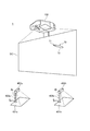
- FIG. 1 is a diagram illustrating a configuration and an installation state of the display system 1.
- the display system 1 includes two first document cameras 4a (document camera, first document camera) and second document camera 4b (document camera, second document camera) on a projector 100 (display device). It has a configuration with a wired connection.
- first document camera 4a and the second document camera 4b are not distinguished, they are expressed as “document camera 4”.
- the number of document cameras 4 connected to the projector 100 is not limited, and one document camera 4 may be connected, or three or more document cameras 4 may be connected.
- the projector 100 is installed above or obliquely above the screen SC (display surface), and projects an image toward the screen SC.
- the screen SC is a flat plate or curtain fixed to the wall surface or standing on the floor surface.
- the present invention is not limited to this example, and the wall surface can be used as the screen SC.
- the projector 100 may be attached to the upper part of the wall surface used as the screen SC.
- the projector 100 may be connected to an image supply device such as a PC (personal computer), a video playback device, a DVD playback device, or a Blu-ray (registered trademark) Disc (Blu-ray Disc) playback device.
- the projector 100 projects an image on the screen SC based on an analog image signal or digital image data supplied from the image supply device.
- the projector 100 may read out image data stored in the built-in storage unit 60 (FIG. 3) or an externally connected storage medium, and display an image on the screen SC based on the image data.
- the projector 100 has a function of detecting a user operation on the screen SC.
- the user holds the shaft portion 72 of the pen-type indicator 70 in his / her hand and operates the screen SC with the tip portion 71 of the indicator 70.
- This operation includes an operation of designating (instructing) a position on the screen SC by the tip portion 71, an operation of sequentially instructing different positions on the screen SC, and the like.
- the operation of instructing the position on the screen SC is an operation of bringing the distal end portion 71 of the indicator 70 into contact with a predetermined position of the screen SC for a predetermined time.
- the operation of sequentially instructing different positions on the screen SC is an operation of drawing a character, a figure or the like by moving the tip 71 while contacting the screen SC.
- the projector 100 detects an operation performed by the user with the indicator 70 and reflects the detected operation on the image of the screen SC. For example, the projector 100 realizes a GUI (Graphical User Interface) operation for executing the function of the projector 100 based on the coordinates of the operation position indicated by the distal end portion 71. Further, the projector 100 has a drawing function for generating characters and figures along the trajectory of the operation position of the tip 71 and projecting the generated characters and figures onto the screen SC.
- GUI Graphic User Interface
- the first document camera 4a includes a camera head 402a and a column 403a that supports the camera head 402a.
- the camera head 402a includes an imaging unit 410a (FIG. 2) that captures the lower part, images a subject placed on a placement surface 401a installed below the camera head 402a, and takes captured image data (image information) as a projector.
- the second document camera 4b includes a camera head 402b corresponding to the camera head 402b, a column 403b corresponding to the column 403a, and a mounting surface 401b corresponding to the mounting surface 401a.
- the display system 1 is used in the following manner, for example, in a presentation performed by a presenter.
- the document camera 4 captures a material (subject) on which photographs, diagrams, and other information used for presentation are printed, and transmits captured image data based on the captured result to the projector 100.
- the projector 100 projects (displays) an image based on the captured image data received from the document camera 4 on the screen SC.
- the presenter uses information based on the image as appropriate, for example, by pointing the image projected on the screen SC, and makes a presentation while supplementing the explanation given by the presenter.
- the image displayed on the screen SC can be switched between an image based on the image captured by the first document camera 4a and an image based on the image captured by the second document camera 4b.
- the presenter appropriately switches the image displayed on the screen SC between an image based on the image captured by the first document camera 4a and an image based on the image captured by the second document camera 4b, according to the explanation given by the presenter.
- the presenter performs processing based on the function of each document camera 4 with respect to the first document camera 4a and the second document camera 4b by a simple method without interrupting the presentation as described later. Execution can be instructed and processing can be executed.
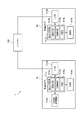
- FIG. 2 is a functional block diagram of the first document camera 4a, the second document camera 4b, and the projector 100.
- the first document camera 4a includes a document camera control unit 411a, an imaging unit 410a, an interface (I / F) unit 412a (communication processing unit), and an external storage medium control unit 416a. Prepare.
- the document camera control unit 411a includes a CPU, ROM, RAM, a predetermined signal processing circuit, and the like, and controls each unit of the first document camera 4a.
- the document camera control unit 411a includes an image output unit 413a, a processing control unit 414a, and a determination unit 415a as functional blocks. These functional blocks execute processing in cooperation with hardware and software such that the CPU reads and executes a corresponding control program stored in the ROM, for example. The functions of these functional blocks and the processing based on the functions will be described later.
- the imaging unit 410a is a digital still camera or a digital video camera, and is installed so as to include the placement surface 401a (FIG. 1) in the imaging range.
- the imaging unit 410a generates captured image data (image information) based on the imaging result, and outputs the generated captured image data to the document camera control unit 411a.
- the image output unit 413a of the document camera control unit 411a transmits captured image data to the projector 100 via the interface unit 412a.
- the interface unit 412a has a circuit including a USB connector for USB connection to the projector 100 and a USB device controller, and communicates with the projector 100 according to the USB standard under the control of the document camera control unit 411a.
- the interface unit 412a may be an interface corresponding to the HDMI (High-Definition Multimedia Interface) (registered trademark) standard, or an interface (for example, D-Sub) that outputs an analog image signal for display. Alternatively, an interface (for example, DVI) that outputs digital video data may be used.
- the interface unit 412a only needs to be connected to the projector 100 and transmit data.
- the interface unit 412a may be configured to be connectable to the projector 100 by wireless communication.
- the external storage medium control unit 416a is configured so that an external storage medium such as an SD memory card or an SDHC memory card can be mounted. Under the control of the document camera control unit 411a, data can be written to the mounted external storage medium. Read data from the storage medium.
- the first document camera 4a has the following functions.
- the first document camera 4a has an autofocus function K1 that automatically performs focusing (autofocus) of the imaging unit 410a when photographing a subject placed on the placement surface 401a.
- the first document camera 4a uses a predetermined instruction by means to be described later as a trigger to repeatedly transmit the captured image data generated based on the imaging result when the predetermined instruction is received at a predetermined cycle.
- It has a camera freeze function K2. While the document camera freeze function K2 is being executed, the projector 100 continuously displays an image having the same content on the screen SC based on the captured image data having the same content received from the first document camera 4a at a predetermined cycle. .
- the first document camera 4a has a document camera zoom function K3 for changing the zoom magnification of the imaging unit 410a. Further, the first document camera 4a is based on photographed image data generated based on the photographed result of the imaging unit 410a, and is obtained by rotating the image orientation of the photographed image data by 180 degrees (hereinafter, “inverted image data”). And a screen 180-degree rotation function K4 for transmitting the generated reverse image data to the projector 100. Further, the first document camera 4a uses, as a trigger, an instruction to execute still image shooting by means to be described later, and captures shot image data generated based on the shooting result when the predetermined instruction is received as a predetermined file.
- It has a still image shooting function K5 for storing it in an external storage medium as a still image file. Further, the first document camera 4a is triggered by an instruction to start moving image shooting by means to be described later as a trigger until the instruction to end moving image shooting by means to be described later is received at a predetermined cycle based on the shooting result. It has a moving image shooting function K6 for storing moving image files based on moving image shooting in an external storage medium for performing moving image shooting for generating moving image files by accumulating the generated captured image data.
- the first document camera 4a reads a file (still image file and moving image file) stored in the external storage medium in a predetermined order with a predetermined instruction by means described later as a trigger, and the read file A reproduction screen function K7 for transmitting photographed image data based on the above to the projector 100.
- the second document camera 4b includes a document camera control unit 411b corresponding to the document camera control unit 411a, an image capturing unit 410b corresponding to the image capturing unit 410a, and an interface unit 412b corresponding to the interface unit 412a.
- the document camera control unit 411b includes an image output unit 413b corresponding to the image output unit 413a, a process control unit 414b corresponding to the process control unit 414a, and a determination unit 415b corresponding to the determination unit 415a.
- the second document camera 4b does not have a component corresponding to the external storage medium control unit 416a, and differs in configuration from the first document camera 4a in that respect.
- the second document camera 4b has the following functions.
- the second document camera 4b has the above-described autofocus function K1, document camera freeze function K2, and document camera zoom function K3.
- the second document camera 4b does not have the screen 180-degree rotation function K4, the still image shooting function K5, the moving image shooting function K6, and the playback screen function K7 of the first document camera 4a.
- the function is different from that of the document camera 4a.
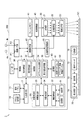
- FIG. 3 is a functional block diagram of the projector 100.
- the projector 100 includes an I / F (interface) unit 11 and an image I / F (interface) unit 12 (communication unit) as interfaces connected to external devices.
- the image I / F unit 12 has an interface corresponding to at least a USB standard (communication standard supported by the first document camera 4a and the second document camera 4b according to the present embodiment), and a control unit described later Communication with the document camera 4 is performed under the control of 30.
- the I / F unit 11 and the image I / F unit 12 may include a connector for wired connection and may include an interface circuit corresponding to this connector.
- the I / F unit 11 and the image I / F unit 12 may include a wireless communication interface.
- Examples of the connector and interface circuit for wired connection include those based on wired LAN, IEEE 1394, USB, and the like.
- Examples of the wireless communication interface include those that comply with a wireless LAN, Bluetooth (registered trademark), or the like.
- the image I / F unit 12 can use an interface for image data such as HDMI, or an interface to which an analog image signal such as D-Sub is input.
- the image I / F unit 12 may include an interface through which audio data is input.
- the I / F unit 11 is an interface that transmits and receives various data to and from an external device such as a PC.
- the I / F unit 11 inputs and outputs data relating to image projection, data for setting the operation of the projector 100, and the like.
- the control unit 30 described later has a function of transmitting / receiving data to / from an external device via the I / F unit 11.
- the image I / F unit 12 is an interface through which digital image data is input.
- the projector 100 according to the present embodiment projects an image based on digital image data input via the image I / F unit 12.
- the image I / F unit 12 includes at least two ports (inputs) including a first USB port P1 (first input terminal) which is a USB port and a second USB port P2 (second input terminal). Terminal).
- the first document camera 4a is connected to the first USB port P1 via a USB cable, and photographed image data which is digital image data is input from the first document camera 4a.
- the second document camera 4b is connected to the second USB port P2 via a USB cable, and photographed image data that is digital image data is input from the second document camera 4b.
- the projector 100 may have a function of projecting an image based on an analog image signal.
- the image I / F unit 12 converts an analog image signal into digital image data and an analog image interface.
- the projector 100 includes a projection unit 20 (display unit) that forms an optical image.
- the projection unit 20 includes a light source unit 21, a light modulation device 22, and a projection optical system 23.
- the light source unit 21 includes a light source including a xenon lamp, an ultra-high pressure mercury lamp, an LED (Light Emitting Diode), a laser light source, or the like.
- the light source unit 21 may include a reflector and an auxiliary reflector that guide light emitted from the light source to the light modulation device 22.
- the projector 100 includes a lens group (not shown) for enhancing the optical characteristics of the projection light, a polarizing plate, or a light control element that reduces the amount of light emitted from the light source on the path to the light modulation device 22. You may have.
- the light modulator 22 includes, for example, three transmissive liquid crystal panels corresponding to the three primary colors of RGB, and modulates the light transmitted through the liquid crystal panel to generate image light.
- the light from the light source unit 21 is separated into three color lights of RGB, and each color light is incident on the corresponding liquid crystal panel.
- the color light modulated by passing through each liquid crystal panel is combined by a combining optical system such as a cross dichroic prism and emitted to the projection optical system 23.
- the projection optical system 23 includes a lens group that guides the image light modulated by the light modulation device 22 toward the screen SC and forms an image on the screen SC. Further, the projection optical system 23 may include a zoom mechanism for enlarging / reducing the display image on the screen SC and adjusting the focus, and a focus adjusting mechanism for adjusting the focus. When the projector 100 is a short focus type, the projection optical system 23 may be provided with a concave mirror that reflects image light toward the screen SC.
- the projection unit 20 is connected to a light source driving unit 45 that turns on the light source unit 21 according to the control of the control unit 30 and a light modulation device driving unit 46 that operates the light modulation device 22 according to the control of the control unit 30.
- the light source drive unit 45 may have a function of adjusting the light amount of the light source unit 21 by switching the light source unit 21 on and off.
- the projector 100 includes an image processing system that processes an image projected by the projection unit 20.
- the image processing system includes a control unit 30 that controls the projector 100, a storage unit 60, an input receiving unit 17, an image processing unit 40, a light source driving unit 45, and a light modulation device driving unit 46.
- a frame memory 41 is connected to the image processing unit 40, and a position detection unit 50 is connected to the control unit 30. These units may be included in the image processing system.
- the control unit 30 controls each unit of the projector 100 by executing a predetermined control program 61.
- the storage unit 60 stores a control program 61 executed by the control unit 30.
- the storage unit 60 also stores an object related information table 62.
- the object related information table 62 will be described later.
- the image processing unit 40 processes the image data input via the image I / F unit 12 under the control of the control unit 30, and outputs an image signal to the light modulation device driving unit 46.
- the processing executed by the image processing unit 40 includes 3D (stereoscopic) image and 2D (planar) image discrimination processing, resolution conversion processing, frame rate conversion processing, distortion correction processing, digital zoom processing, color tone correction processing, luminance correction processing, and the like. is there.
- the image processing unit 40 executes processing designated by the control unit 30 and performs processing using parameters input from the control unit 30 as necessary. Of course, it is also possible to execute a combination of a plurality of processes.
- the image processing unit 40 is connected to the frame memory 41.
- the image processing unit 40 expands the image data input from the image input I / F 12 in the frame memory 41, and executes the various processes described above on the expanded image data.
- the image processing unit 40 reads out the processed image data from the frame memory 41, generates R, G, and B image signals corresponding to the image data, and outputs them to the light modulation device driving unit 46.
- the light modulation device driving unit 46 is connected to the liquid crystal panel of the light modulation device 22.
- the light modulator driving unit 46 drives the liquid crystal panel based on the image signal input from the image processing unit 40 and draws an image on each liquid crystal panel.
- the input receiving unit 17 is connected to a remote control light receiving unit 18 and an operation panel 19 that function as an input device, and detects an operation via the remote control light receiving unit 18 and the operation panel 19.
- the remote control light receiving unit 18 receives an infrared signal transmitted by a remote controller (not shown) used by the user of the projector 100 in response to a button operation.
- the remote control light receiving unit 18 decodes the infrared signal received from the remote control, generates operation data indicating the operation content in the remote controller (remote control), and outputs the operation data to the control unit 30.
- the operation panel 19 is provided in the exterior casing of the projector 100 and includes various switches and indicator lamps.
- the input receiving unit 17 appropriately turns on and off the indicator lamp of the operation panel 19 according to the operation state and setting state of the projector 100 according to the control of the control unit 30.
- operation data corresponding to the operated switch is output from the input receiving unit 17 to the control unit 30.
- the position detection unit 50 detects the operation position by the indicator 70.
- the position detection unit 50 includes an imaging unit 51, a transmission unit 52, an imaging control unit 53, an object detection unit 54, and a coordinate calculation unit 55.
- the photographing unit 51 forms a photographed image obtained by photographing a range including the screen SC and its peripheral part as a photographing range.
- the imaging unit 51 includes an infrared imaging element that captures infrared light and an interface circuit, and performs imaging using infrared light. Either an CCD or a CMOS can be used as the image pickup element, and other elements can also be used.
- the shooting direction and shooting range (angle of view) of the shooting unit 51 are directed in the same direction or substantially the same direction as the projection optical system 23, and cover the range in which the projection optical system 23 projects an image on the screen SC.
- the photographing unit 51 outputs photographed image data.
- the imaging control unit 53 controls the imaging unit 51 according to the control of the control unit 30 and causes the imaging unit 51 to perform imaging.
- the imaging control unit 53 acquires the captured image data of the imaging unit 51 and outputs it to the target detection unit 54.
- An image of infrared light emitted from the indicator 70 is captured in the captured image data captured by the imaging unit 51 with infrared light.
- the transmission unit 52 transmits an infrared signal to the indicator 70 according to the control of the imaging control unit 53.
- the transmission unit 52 has a light source such as an infrared LED, and turns on and off the light source according to the control of the imaging control unit 53.
- the object detection unit 54 detects the infrared light image captured in the captured image data of the imaging unit 51, and detects the coordinates of the operation position of the indicator 70 in the captured image data. Further, the target detection unit 54 determines whether or not the tip portion 71 of the indicator 70 is in contact with the screen SC, and generates touch information indicating whether or not the tip portion 71 is in contact with the screen SC. . A method for determining whether or not the tip 71 of the indicator 70 is in contact with the screen SC will be described later.
- the coordinates of the operation position of the indicator 70 detected by the target detection unit 54 are the coordinates in the captured image data of the imaging unit 51.
- the coordinate calculation unit 55 converts the coordinates of the operation position into the coordinates of the operation position on the screen SC. In this embodiment, it is converted into coordinates in the projection image projected by the projection unit 20.
- the coordinates in the projected image are affected by various factors such as the distance between the projector 100 and the screen SC, the zoom ratio in the projection optical system 23, the installation angle of the projector 100, and the distance between the photographing unit 51 and the screen SC.
- the coordinate calculation unit 55 calculates the coordinates of the operation position in the display image of the screen SC from the coordinates of the operation position in the captured image data based on the result of calibration performed in advance.
- a predetermined pattern image is projected from the projection unit 20 onto the screen SC, and the displayed pattern image is photographed by the photographing unit 51.
- the correspondence (coordinate conversion parameter) between the coordinates in the captured image data and the coordinates on the display image of the screen SC is derived.
- the control unit 30 can specify the operation position for the projection image drawn in the frame memory 41.
- the indicator 70 includes a control unit 73, a transmission / reception unit 74, an operation switch 75, and a power source unit 76. These units are accommodated in a shaft unit 72 (FIG. 1).
- the control unit 73 is connected to the transmission / reception unit 74 and the operation switch 75 and detects the on / off state of the operation switch 75.
- the transmission / reception unit 74 includes a light source such as an infrared LED and a light receiving element that receives infrared light.
- the power supply unit 76 includes a dry battery or a secondary battery as a power supply, and supplies power to the control unit 73, the transmission / reception unit 74, and the operation switch 75.
- the indicator 70 may include a power switch that turns on / off the power supply from the power supply unit 76.
- a method for specifying the operation position of the indicator 70 from the captured image data of the imaging unit 51 by mutual communication between the position detection unit 50 and the indicator 70 will be described.
- the control unit 30 controls the imaging control unit 53 to transmit a synchronization signal from the transmission unit 52. That is, the imaging control unit 53 turns on the light source of the transmission unit 52 at a predetermined cycle in accordance with the control of the control unit 30.
- the infrared light periodically emitted from the transmission unit 52 functions as a synchronization signal that synchronizes the position detection unit 50 and the indicator 70.
- the control unit 73 receives infrared light emitted from the transmission unit 52 of the projector 100 by the transmission / reception unit 74.
- the control unit 73 synchronizes with the timing of this infrared light and transmits and receives the transmission / reception unit with a preset lighting pattern specific to the indicator 70.
- 74 light sources are turned on (emitted). Further, the control unit 73 switches the lighting pattern of the transmission / reception unit 74 according to the operation state of the operation switch 75.
- the target detection unit 54 of the projector 100 can determine the operating state of the indicator 70, that is, whether or not the distal end portion 71 is pressed against the screen SC, based on a plurality of captured image data.
- the control unit 73 repeatedly executes the above pattern while power is supplied from the power supply unit 76. That is, the transmission unit 52 periodically transmits an infrared signal for synchronization to the indicator 70, and the indicator 70 transmits a preset infrared signal in synchronization with the infrared signal transmitted by the transmission unit 52. Send.
- the shooting control unit 53 performs control to match the shooting timing of the shooting unit 51 with the timing when the indicator 70 is turned on.
- the shooting timing is determined based on the timing at which the shooting control unit 53 turns on the transmission unit 52.
- the object detection unit 54 can specify the pattern in which the indicator 70 is turned on depending on whether or not the image of the light of the indicator 70 is reflected in the captured image data of the imaging unit 51.
- the target detection unit 54 determines whether or not the distal end portion 71 of the indicator 70 is pressed against the screen SC based on the plurality of captured image data, and generates touch information.
- the lighting pattern of the indicator 70 may include a pattern unique to each individual indicator 70, or a pattern common to the plurality of indicators 70 and a pattern unique to each individual. In this case, the target detection unit 54 can distinguish each image as an image of a different indicator 70 when the captured image data includes images of infrared light emitted from the plurality of indicators 70.
- the control unit 30 reads out and executes the control program 61 stored in the storage unit 60, thereby executing the functions of the projection control unit 31, the operation acquisition unit 32, the drawing unit 33, the object generation unit 34, and the instruction information transmission unit 35. Realize and control each part of the projector 100.
- the projection control unit 31 acquires the operation content performed by the user operating the remote control.
- the projection control unit 31 controls the image processing unit 40, the light source driving unit 45, and the light modulation device driving unit 46 according to an operation performed by the user, and projects an image on the screen SC. Further, the projection control unit 31 controls the image processing unit 40 to determine the above-described 3D (stereoscopic) image and 2D (planar) image, resolution conversion processing, frame rate conversion processing, distortion correction processing, digital zoom processing, Color tone correction processing, luminance correction processing, and the like are executed. Further, the projection control unit 31 controls the light source driving unit 45 in accordance with the processing of the image processing unit 40 and controls the light amount of the light source unit 21.
- the operation acquisition unit 32 acquires the operation position of the indicator 70 detected by the position detection unit 50.
- the operation acquisition unit 32 displays an image corresponding to the operation position when the position detection unit 50 detects the operation position of the indicator 70 in a state where a GUI operation image such as a menu bar is displayed on the screen SC. Identify and detect instructions. For example, in the state where the menu bar is displayed, an icon in the menu bar corresponding to the operation position of the indicator 70 is specified, and the function of the specified icon is detected.
- the drawing unit 33 draws characters and figures according to the operation position of the indicator 70 detected by the position detection unit 50.
- the drawing unit 33 acquires the locus of the operation position of the indicator 70, and images such as figures such as polygons, straight lines, and curves along the locus. Is generated.
- the type of graphic or image generated by the drawing unit 33 is specified by an operation detected by the operation acquisition unit 32.
- the image generated by the drawing unit 33 is transferred to the image processing unit 40, and the image processing unit 40 combines the drawing image with the image on the frame memory 41 under the control of the projection control unit 31. Thereby, the image drawn by the drawing unit 33 is projected by the projection unit 20.
- the document camera 4 can be connected to the projector 100 according to the present embodiment.
- the operation of the projector 100 when the power is turned on and when the document camera 4 is connected to the projector 100 will be described.
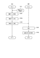
- FIG. 4 is a flowchart showing the operations of the projector 100 and the first document camera 4a when the power of the projector 100 is turned on and when the first document camera 4a is connected to the projector 100.
- 4A shows the operation of the projector 100
- the flowchart of FIG. 4B shows the operation of the first document camera 4a.
- the first document camera 4a is physically connected to the USB port (in this example, the first USB port P1) of the projector 100 via the USB cable. This is triggered by the power being turned on.
- the control unit 30 of the projector 100 detects that the first document camera 4a is physically connected in accordance with the USB standard in the initial process executed when the power is turned on.
- the process of the flowchart of FIG. 4 is performed with a trigger that the first document camera 4a is physically connected to the projector 100 after the power is turned on. In this case, the control unit 30 of the projector 100 detects that the first document camera 4a is physically connected in accordance with the USB standard.
- the image I / F unit 12 of the projector 100 and the interface unit 412a of the first document camera 4a communicate according to the USB standard to communicate with each other. Is established so that bidirectional communication can be performed between the devices according to the USB standard (steps S101 and S201).
- the control unit 30 of the projector 100 controls the image I / F unit 12 to transmit the document camera identification information (identification information) to the first document camera 4a.
- An identification information response request command for requesting a response is transmitted to the first document camera 4a (step S102).
- the document camera identification information is information for uniquely identifying the document camera 4. For example, a serial number assigned to the document camera 4 when the document camera 4 is manufactured can be used as the document camera identification information.
- the document camera identification information received by the projector 100 from the document camera 4 with which the communication path is established when the communication path is established corresponds to “first information”.
- the document camera control unit 411a of the first document camera 4a controls the interface unit 412a to receive the identification information response request command, and based on the command, the first document camera An identification information response command for responding to the document camera identification information 4a is transmitted (step S202).
- the control unit 30 of the projector 100 controls the image I / F unit 12, receives an identification information response command, and acquires document camera identification information based on the command. (Step S103).
- the control unit 30 requests the first document camera 4a to respond to the document camera identification information, and acquires the document camera identification information based on the response to the request.
- the first document camera 4 a functions as a USB device with respect to the projector 100, and the first document camera 4 a is connected to the projector 100 when establishing a communication path between the first document camera 4 a and the projector 100.
- a vendor ID and a product ID that are uniquely assigned to the USB device are transmitted.
- control unit 30 may transmit the document camera identification information from the first document camera 4a without performing step S102 for requesting the document camera 4a to respond to the document camera identification information.
- the control unit 30 refers to the object related information table 62 stored in the storage unit 60, and determines whether or not a record having the document camera identification information acquired in step S103 exists in the object related information table 62. (Step S104).
- the object related information table 62 shows a state where a record having document camera identification information of the document camera 4 exists.
- step S104 if the document camera 4 has been connected to the projector 100 in the past, the control unit 30 has a record having the document camera identification information acquired in step S103 in the object related information table 62. Then, it is determined. On the other hand, in step S104, if the document camera 4 has not been connected to the projector 100 in the past, the control unit 30 has a record having the document camera identification information acquired in step S103 in the object related information table 62. It is determined not to.
- step S104 If it is determined that there is a record having the document camera identification information acquired in step S103 in the object related information table 62 (step S104: YES), the control unit 30 proceeds to step S107 described later.
- step S104 When it is determined that there is no record having the document camera identification information acquired in step S103 in the object related information table 62 (step S104: NO), the control unit 30 executes the following process (step S105). That is, the control unit 30 controls the image I / F unit 12 to respond to the first document camera 4a with function identification information (hereinafter referred to as “function identification information”) of the first document camera 4a.
- function identification information hereinafter referred to as “function identification information”
- the determination unit 415a of the document camera control unit 411a of the first document camera 4a controls the interface unit 412a to receive the function information response request command, and based on the command, A function information response command for responding to the function identification information of the function of the first document camera 4a is transmitted (step S203). More specifically, in step S203, the determination unit 415a determines the function of the first document camera 4a. For example, data including information indicating the function of the first document camera 4a is stored in advance in a predetermined storage area of the first document camera 4a, and the determination unit 415a has the first document camera 4a based on the data. Determine function.
- the determination unit 415a acquires the predetermined information, Based on the predetermined information, the function of the first document camera 4a is determined. Next, the determination unit 415a generates a function information response command including function identification information of the function of the determined first document camera 4a. Next, the determination unit 415a transmits the generated function information response command.
- the first document camera 4a includes the autofocus function K1, the document camera freeze function K2, the document camera zoom function K3, the screen 180-degree rotation function K4, the still image shooting function K5, the moving image shooting function K6, and the playback. It has a screen function K7. Accordingly, in step S203, the determination unit 415a generates and transmits a function information response command including function identification information of these seven functions.
- the function of the document camera 4 corresponds to “a process executable by the document camera 4”.
- control unit 30 of the projector 100 controls the image I / F unit 12 to receive a function information response command, and one item is stored in the object related information table 62 based on the command. Is generated (step S106).
- FIG. 5A is a diagram schematically showing the data structure of a record included in the object related information table 62.
- one record in the object related information table 62 has document camera identification information and object related information.
- the object related information has one or a plurality of function related information.
- the function related information includes function identification information, display valid / invalid information, and icon data.
- the object related information corresponds to “information related to an object”.
- the display valid / invalid information will be described in detail later.
- the display valid / invalid information is either display valid information indicating that an icon of a function corresponding to the document camera tool box is displayed or display invalid information indicating that an icon of a function corresponding to the document camera tool box is not displayed.
- Take the value of Icon data is image data of an icon of a corresponding function.
- step S ⁇ b> 106 the control unit 30 acquires function identification information included in the function information response command received from the first document camera 4 a (each of the plurality of function identification information when a plurality of function identification information is included). To do.
- the control unit 30 includes function-related information configured by a combination of function identification information, display valid information that is a default value of display valid / invalid information, and corresponding icon data. Is generated.
- the storage unit 60 stores in advance a table in which function identification information and icon data are associated with each of the functions that the document camera 4 that can be connected to the projector 100 can have. Obtains corresponding icon data for each of the function identification information based on the table.
- the document camera 4 may store the icon data, and the control unit 30 may communicate with the document camera 4 and acquire icon data from the document camera 4.
- the control unit 30 generates object related information configured by each combination of the generated function related information.
- the control unit 30 generates one record in the object related information table 62 in which the generated object related information is associated with the document camera identification information acquired in step S103.
- FIG. 5B is a diagram schematically showing the contents of a record generated by the control unit 30 based on the model information response command received from the first document camera 4a.
- the record related to the first document camera 4a includes document camera identification information of the first document camera 4a and object-related information related to the first document camera 4a.
- the object related information includes function related information corresponding to each of the functions of the first document camera 4a.
- the function-related information includes function identification information of a corresponding function, display valid information (default value of display valid / invalid information), and corresponding icon data.
- the storage unit 60 in which the object related information table 62 is stored includes a non-volatile memory and stores data in a non-volatile manner. Accordingly, the object related information table 62 is continuously stored in the storage unit 60 even when the power of the projector 100 is turned off.
- step S106 After executing the processing of step S106, the control unit 30 moves the processing procedure to step S107.
- step S107 the control unit 30 refers to the object related information table 62, specifies the record having the document camera identification information acquired in step S103 from the records included in the table, and sets the object related information included in the specified record. get.
- the object related information acquired by the control unit 30 in step S107 is object related information related to the document camera 4 (in this example, the first document camera 4a) that has established the communication path in step S101.
- step S108 the control unit 30 executes correspondence display processing (step S108). Corresponding display processing is performed when there is no document camera 4 connected to the projector 100 other than the document camera 4 for which the communication path has been established in step S101 (case 1), and for cases other than the document camera 4 for which the communication path has been established in step S101.
- a document camera 4 (hereinafter referred to as “other document camera 4”) is already connected to the projector 100, an image based on an input from the other document camera 4, and a document camera corresponding to the document camera 4
- the contents of the process are different when the control tool box is displayed on the screen SC (case 2).
- the correspondence display process will be described separately for case 1 and case 2.
- the control unit 30 validates the input from the USB port (input terminal) to which the document camera 4 having established the communication path in step S101 is connected, and the captured image data input through the USB port. Shifts to a state of being output to the image processing unit 40. In response to the transition to the state, display of the image on the screen SC based on the captured image data input through the enabled USB port is started.
- the object generation unit 34 of the control unit 30 generates image data of the document camera control tool box (object) based on the object related information acquired in step S107.
- the object generation unit 34 controls the image processing unit 40 based on the generated image data of the document camera control toolbox, and is input from the image I / F unit 12 to the image processing unit 40 and stored in the frame memory 41.
- the developed captured image data is processed, and a document camera control tool box is displayed at a predetermined position on the screen SC.
- the display on the screen SC of the document camera control tool box will be described in detail.
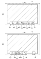
- FIG. 6A shows an example of the first document camera control tool box TB1, which is a document camera control tool box for controlling the first document camera 4a displayed on the screen SC in the process of step S108, and the first document. It is a figure which shows the image G1 which is an image based on the picked-up image data input from the camera 4a.
- the document camera control toolbox is a GUI having one or a plurality of icons, and each icon can be operated by the indicator 70.
- the first document camera control tool box TB1 includes a plurality of function icons KA (seven function icons KA1 to KA7) in the example of FIG. 6A and a delete icon.
- SA and an edit icon HA are provided.
- a function icon KA1 is an icon representing the autofocus function K1.
- the function icon KA2 is an icon representing the document camera freeze function K2.
- the function icon KA3 is an icon representing the document camera zoom function K3.
- the function icon KA4 is an icon representing the screen 180-degree rotation function K4.
- the function icon KA5 is an icon representing the still image shooting function K5.
- the function icon KA6 is an icon representing the moving image shooting function K6.
- the function icon KA7 is an icon representing the playback screen function K7. Operations of the projector 100 and the document camera 4 when the function icon KA is operated by the indicator 70 will be described.
- the delete icon SA is an icon operated when deleting the first document camera control tool box TB1 from the screen SC.
- the edit icon HA is an icon operated when editing the contents of the first document camera control tool box TB1. The process of the control unit 30 when the edit icon HA is operated will be described later.
- step S108 the object generation unit 34 of the control unit 30 specifies function identification information associated with display valid information in the object related information acquired in step S107.
- the object generation unit 34 acquires icon data associated with the specified function identification information.
- the object generation unit 34 arranges the function icons KA in a predetermined order, and then the first document camera control tool box TB1 in which the delete icon SA and the edit icon HA are arranged.
- Image data is generated.
- the image data of the delete icon SA and the edit icon HA are stored in advance in a predetermined storage area.
- the object generation unit 34 controls the image processing unit 40 based on the generated image data of the first document camera control tool box TB1, and is input from the image I / F unit 12 to the image processing unit 40 to receive frames.
- the image data (photographed image data) developed in the memory 41 is processed, and a document camera control tool box is displayed at a predetermined position on the screen SC.
- the control unit 30 manages the coordinates of the area in which the image data of each icon included in the first document camera control tool box TB1 is developed in the frame memory 41. Thereby, when the user operates any icon included in the first document camera control tool box TB1 with the indicator 70, the control unit 30 is based on the operation position of the indicator 70 acquired by the operation acquisition unit 32. The operated icon can be specified.
- the control unit 30 does not switch the USB port that validates the input, and continues displaying the image based on the captured image data input from the other document camera 4 that is already displayed. Further, the control unit 30 continues to display the document camera control tool box related to the other document camera 4. On the other hand, the control unit 30 does not execute the display of the document camera control tool box related to the document camera 4 (in this example, the first document camera 4a) that has established the communication path in step S101, and moves to a predetermined position on the screen SC. A switching icon CA is displayed.
- FIG. 6B shows a case in which, in case 2, when the other document camera is the second document camera 4b, a second document camera control tool box TB2, which is a document camera control tool box related to the second document camera 4b, and It is a figure which shows switching icon CA displayed on screen SC with the image G2 based on the imaging
- Image data relating to the switching icon CA is stored in advance in a predetermined storage area.
- the control unit 30 processes image data (captured image data) input from the image I / F unit 12 to the image processing unit 40 and developed in the frame memory 41 based on the image data of the switching icon CA. Then, the switching icon CA is displayed at a predetermined position on the screen SC.
- control unit 30 manages the coordinates of the area where the image data of the switching icon CA is developed in the frame memory 41. Thereby, when the user operates the switching icon CA with the indicator 70, the control unit 30 can detect that the switching icon CA has been operated based on the operation position of the indicator 70 acquired by the operation acquisition unit 32. .
- the control unit 30 executes the following processing. That is, the control unit 30 switches the input terminal that validates the image displayed on the screen SC from one input terminal to another input terminal. Thereby, the image displayed on the screen SC is input from the document camera 4 connected to the other input terminal from the image based on the photographed image data input from the document camera 4 connected to the one input terminal. Switch to an image based on the captured image data. Further, the control unit 30 stops displaying the document camera control tool box related to the document camera 4 connected to the one input terminal whose input is invalidated by switching.
- the object generation unit 34 based on the document camera identification information received from the document camera 4 when establishing a communication path with the document camera 4 connected to another input terminal whose input is validated by switching, The corresponding object related information is acquired from the object related table, the image data of the document camera control tool box related to the document camera 4 is generated based on the acquired object related information, and the document camera control is performed based on the generated image data. Display the toolbox.
- the control unit 30 continuously displays the switching icon CA.
- the switching icon CA is operated.
- the control unit 30 executes the following processing. That is, the control unit 30 switches the USB port that validates the input from the first USB port P1 to the second USB port P2.
- the image displayed on the screen SC is switched from an image based on the captured image data input from the first document camera 4a to an image based on the captured image data input from the second document camera 4b.
- the control unit 30 stops displaying the first document camera control tool box TB1 related to the first document camera 4a.
- the object generation unit 34 of the control unit 30 selects the corresponding object related information from the object related table based on the document camera identification information received from the second document camera 4b when the communication path with the second document camera 4b is established. To get.
- the object generation unit 34 generates image data of the second document camera control tool box TB2 related to the second document camera 4b based on the acquired object related information, and based on the generated image data, the second document camera The control tool box TB2 is displayed.
- control unit 30 displays the edit screen HG on the screen SC.
- FIG. 7 is a diagram illustrating an example of the edit screen HG displayed on the screen SC.
- the edit screen HG displays a function name (hereinafter referred to as “function name”) for each function of the corresponding document camera 4 (the document camera 4 related to the document camera control tool box including the operated edit icon HA). "Function name”) is displayed in a list.
- the edit screen HG associates each of the function names displayed in the list with information indicating whether the display of the function icon KA of the corresponding function is valid or invalid, and a valid / invalid switch button BB (described later). indicate.
- the display of the function icon KA relating to the first function means that the function icon KA relating to the first function is included in the tool box when the document camera control tool box is displayed.
- the display of the function icon KA related to the first function being invalid means that when the document camera control tool box is displayed, the function icon KA related to the first function is not included in the tool box.
- the control unit 30 When displaying the editing screen HG, the control unit 30 acquires the object related information of the corresponding document camera 4 from the object related information table 62 by the method described above. Next, the control unit 30 acquires the function identification information of the function of the corresponding document camera 4 based on the function related information included in the object related information.
- a table in which function identification information and a function name are associated with each other is stored in advance in a predetermined storage area. Based on the table, the control unit 30 acquires function names corresponding to the acquired function identification information.
- the control unit 30 acquires display valid / invalid information of the function of the corresponding document camera 4 based on the object related information.
- the control unit 30 generates image data of the editing screen HG based on the acquired function name and display valid / invalid information.
- the control unit 30 displays the editing screen HG on the screen SC based on the generated image data of the editing screen HG.
- the valid / invalid switch button BB is a button that can be operated by the indicator 70.
- the control unit 30 displays the corresponding display valid / invalid information included in the object related information of the corresponding record in the object related information table 62. Is updated from display valid information to display invalid information, or from display invalid information to display valid information.
- the function icon KA corresponding to the document camera control tool box displayed based on the object related information is displayed. Change from state to non-displayed state.
- the corresponding function icon KA is not displayed in the document camera control tool box displayed based on the object related information. Changes to the displayed state.
- the updated object related information is stored in the object related information table 62 in a nonvolatile manner.
- a document camera control tool box related to one document camera 4 is displayed triggered by a predetermined event such as turning on the power of the projector 100, connecting the document camera 4 to the projector 100, or operating the switching icon CA.
- the toolbox is displayed based on the updated object related information. Therefore, when the user deletes the function icon KA related to one function of one document camera 4 from the document camera control toolbox using the editing screen HG, the corresponding one displayed as a trigger after that is displayed.
- the function icon KA related to the first function is not displayed in the document camera control toolbox of the document camera 4. In other words, without the user performing intentional work, the function icon KA related to the function deleted from the document camera control toolbox by the user can be displayed, which is highly convenient for the user.
- FIG. 8 is a flowchart showing operations of the projector 100 and the first document camera 4a when the function icon KA included in the document camera control toolbox is operated by the indicator 70.
- FIG. 8A shows the operation of the projector 100
- FIG. 8B shows the operation of the first document camera 4a.
- the description using the flowchart of FIG. 8 assumes the following. That is, the first document camera 4a is connected to the first USB port P1, the input of the first USB port P1 is valid, and the first document camera control tool box TB1 related to the first document camera 4a is displayed on the screen SC. Assumes that
- the user operates one of the function icons KA included in the document camera control tool box using the indicator 70 (step SX1).
- the control unit 30 of the projector 100 specifies the operated function icon KA based on the operation position of the indicator 70 acquired by the operation acquisition unit 32 (step S301).
- the instruction information transmission unit 35 of the control unit 30 generates a control command (instruction information) that causes the first document camera 4a to execute processing based on the function corresponding to the function icon KA specified in step S301 (step S302).
- the operated function icon KA is an icon related to the autofocus function K1
- the instruction information transmission unit 35 generates a control command that instructs the first document camera 4a to execute autofocus.
- the control program for realizing the function of the instruction information transmission unit 35 includes an algorithm for generating a control command that instructs execution of processing based on a function for each of the functions that the document camera 4 that can be connected to the projector 100 may have. Has been implemented.
- the instruction information transmission unit 35 controls the image I / F unit 12 to transmit the generated control command to the first document camera 4a (step S303).
- the area where the function icon KA operated by the indicator 70 is displayed corresponds to the “first position”, and the processing based on the function corresponding to the operated function icon KA is “first processing”. It corresponds to.
- the process control unit 414a of the document camera control unit 411a of the first document camera 4a controls the interface unit 412a to receive a control command (step S401).
- the process control unit 414a executes a process based on the function corresponding to the operated function icon KA based on the received control command (step S402). For example, when the received control command is a control command instructing execution of processing based on the autofocus function K1, the process control unit 414a executes autofocus.
- the user performs a simple operation of operating the function icon KA included in the document camera control tool box with the indicator 70 without directly operating the document camera 4.
- the document camera 4 can execute a desired process. Therefore, when the display system 1 is used for a presentation, if the presenter wants the document camera 4 to execute a predetermined process, the presenter interrupts the presentation and moves to the position of the document camera 4. It is possible to cause the document camera 4 to execute the predetermined processing by a simple operation of operating the function icon KA included in the document camera control tool box with the indicator 70 without operating the document camera 4.
- the projector 100 includes the image I / F unit 12 (communication unit) that communicates with the document camera 4 and the document camera 4 via the image I / F unit 12.
- a projection unit 20 (display unit) that displays an image based on the received captured image data (image information) on a screen SC (display surface), a position detection unit 50 that detects the position of the indicator 70 with respect to the screen SC, and a position
- the document camera is connected via the image I / F unit 12.
- the 4 includes an instruction information transmission unit 35 that transmits a control command (instruction information) that causes a process (first process) based on a function related to the function icon KA. According to this configuration, the user can cause the document camera 4 to execute a desired process with a simple operation of operating the function icon KA with the indicator 70 without directly operating the document camera 4. .
- the projector 100 further includes an object generation unit 34 that generates a document camera control tool box (object), and the projection unit 20 displays the document camera control tool box generated by the object generation unit 34.
- object a document camera control tool box
- the projection unit 20 displays the document camera control tool box generated by the object generation unit 34.
- the object generation unit 34 receives document camera identification information (first information) from the document camera 4 via the image I / F unit 12 and controls the document camera based on the document camera identification information. Generate a toolbox. According to this configuration, the object generation unit 34 can generate a document camera control tool box corresponding to the document camera 4 based on the document camera identification information.
- the projector 100 includes a storage unit 60 that stores document camera identification information and object related information (information related to an object) in association with each other.
- the object generation unit 34 receives the document camera identification information from the document camera 4 via the image I / F unit 12, and based on the object related information stored in the storage unit 60 in association with the document camera identification information. Generate a document camera control toolbox.
- the object generation unit 34 can generate a document camera control tool box corresponding to the document camera 4 based on information in which the document camera identification information stored in the storage unit 60 is associated with the object related information. .
- the projector 100 includes a first USB port P1 (first input terminal) and a second USB port P2 (second input terminal). Then, the object generation unit 34 generates an image displayed by the projection unit 20 from an image based on captured image data input via the first USB port P1 to which the first document camera 4a (first document camera) is connected. When the image is switched to the image based on the photographed image data input through the second USB port P2 to which the second document camera 4b is connected, the second document is based on the document camera identification information received from the second document camera 4b.
- a camera control tool box TB2 is generated. According to this configuration, the document camera control tool box corresponds to the image after switching according to switching from the image based on the photographing result of the first document camera 4a to the image based on the photographing result of the second document camera 4b. Can be.
- the object generation unit 34 changes the aspect of the document camera control tool box in accordance with the operation of the indicator 70 corresponding to the editing screen HG (in response to a predetermined operation by the indicator 70). .
- the user can change the aspect of the document camera control tool box by a simple method of operation by the indicator 70.
- the first document camera 4a also includes an interface unit 412a (communication processing unit) that communicates with the projector 100, an imaging unit 410a that performs imaging, and captured image data based on the imaging results of the imaging unit 410a.
- the image output unit 413a that transmits to the projector 100 via the interface unit 412a, and the control command generated by the projector 100 based on the operation of the area corresponding to the function icon KA of the screen SC by the indicator 70 are displayed on the interface unit 412a.
- a processing control unit 414a that performs processing based on the function related to the operated function icon KA based on the received control command. According to this configuration, the user can cause the document camera 4 to execute a desired process with a simple operation of operating the function icon KA with the indicator 70 without directly operating the document camera 4. .
- the first document camera 4a includes a determination unit 415a that determines a function (executable process) and transmits information indicating the function to the projector 100 via the interface unit 412a.
- the document camera 4 can notify the projector 100 of the function of the document camera 4 by the function of the determination unit 415a, and the projector 100 has a function corresponding to the function of the document camera 4 based on the notification.
- a document camera control toolbox including an icon KA can be displayed. The same applies to the second document camera 4b.
- the indicator used for the operation on the screen SC is not limited to the pen-type indicator 70, and a user's finger, a laser pointer, an indicator bar, or the like may be used, and the shape and size thereof are not limited.
- the position detection unit 50 captures the screen SC by the photographing unit 51 and specifies the position of the indicator 70, but the present invention is not limited to this.
- the photographing unit 51 is not limited to the one provided in the main body of the projector 100 and photographing the projection direction of the projection optical system 23.
- the imaging unit 51 may be arranged separately from the main body of the projector 100, or the imaging unit 51 may perform imaging from the side or front of the screen SC.
- a plurality of imaging units 51 may be arranged, and the target detection unit 54 may detect the operation position based on the captured image data of the plurality of imaging units 51.
- the synchronization signal is an infrared signal. It is not limited to.
- a synchronization signal may be transmitted by radio wave communication or ultrasonic wireless communication.
- the function of the position detection unit 50 can be realized as a device independent of the projector 100.
- the display device of the present invention is not limited to the projector 100 that projects an image on the screen SC as described above, but may be a liquid crystal monitor or a liquid crystal television that displays an image on a liquid crystal display panel, or a plasma display panel (PDP).
- Self-luminous type such as a monitor device or a television receiver for displaying images on an organic EL display panel called an OLED (Organic Electro-Luminescence), a monitor device or a television receiver, an OLED (Organic Light-emitting Diode), etc.
- OLED Organic Electro-Luminescence
- a monitor device or a television receiver for displaying images on an organic EL display panel
- OLED Organic Light-emitting Diode
- Various display devices such as these display devices are also included in the display system of the present invention.
- a liquid crystal display panel, a plasma display panel, and an organic EL display panel correspond to the display unit and the display surface.
- the light modulation device 22 that modulates the light emitted from the light source has been described by taking as an example a configuration using three transmissive liquid crystal panels corresponding to RGB colors. Is not limited to this. For example, a configuration using three reflective liquid crystal panels may be used, or a method in which one liquid crystal panel and a color wheel are combined may be used. Alternatively, a system using three digital mirror devices (DMD), a DMD system combining one digital mirror device and a color wheel, or the like may be used. When only one liquid crystal panel or DMD is used as the light modulation device 22, a member corresponding to a synthetic optical system such as a cross dichroic prism is unnecessary. In addition to the liquid crystal panel and DMD, any light modulation device capable of modulating light emitted from the light source can be employed without any problem.
- a configuration using three reflective liquid crystal panels may be used, or a method in which one liquid crystal panel and a color wheel are combined may be used.
- the functional blocks shown in the functional block diagrams of FIGS. 2 and 3 indicate functional configurations of the document camera 4 and the projector 100, and do not limit specific mounting forms. In other words, it is not necessary to implement hardware corresponding to the functional blocks in the figure, and it is of course possible to adopt a configuration in which the functions of a plurality of functional units are realized by one processor executing a program.
- a part of the function realized by software may be realized by hardware, or a part of the function realized by hardware may be realized by software. In the flow shown in FIG.
- the object related information table 62 is referred to, and the document camera identification acquired in step S ⁇ b> 103 from the record of the table.
- a record having information is specified and object related information included in the specified record is acquired, the present invention is not limited to this.
- a function information response command including function identification information may be transmitted from the document camera 4 to the projector 100 without going through steps S102 to S105 and S202, and object related information may be acquired based on the function information response command.
- the external device that can be connected to the projector 100 is not limited to the document camera 4.
- any device that can output images and sounds such as a desktop computer, a mobile phone including a smartphone, a video / music player, and a TV broadcast tuner device, may be used.
- the specific configuration of the interface that connects the external device and the projector 100 is not limited, and any interface that can transmit an analog image signal, an audio signal, or digital data can be applied without limitation.
- the specific detailed configuration of each other part of the device constituting the display system 1 can be arbitrarily changed without departing from the gist of the present invention.
Landscapes
- Engineering & Computer Science (AREA)
- Multimedia (AREA)
- Signal Processing (AREA)
- Theoretical Computer Science (AREA)
- General Engineering & Computer Science (AREA)
- General Physics & Mathematics (AREA)
- Physics & Mathematics (AREA)
- Human Computer Interaction (AREA)
- Studio Devices (AREA)
- Controls And Circuits For Display Device (AREA)
- Projection Apparatus (AREA)
- User Interface Of Digital Computer (AREA)
- Position Input By Displaying (AREA)
- Transforming Electric Information Into Light Information (AREA)
Priority Applications (1)
| Application Number | Priority Date | Filing Date | Title |
|---|---|---|---|
| US15/560,338 US10536627B2 (en) | 2015-03-30 | 2016-03-18 | Display apparatus, method of controlling display apparatus, document camera, and method of controlling document camera |
Applications Claiming Priority (2)
| Application Number | Priority Date | Filing Date | Title |
|---|---|---|---|
| JP2015-068092 | 2015-03-30 | ||
| JP2015068092A JP2016189517A (ja) | 2015-03-30 | 2015-03-30 | 表示装置、表示装置の制御方法、書画カメラ、及び、書画カメラの制御方法 |
Publications (1)
| Publication Number | Publication Date |
|---|---|
| WO2016157803A1 true WO2016157803A1 (ja) | 2016-10-06 |
Family
ID=57005839
Family Applications (1)
| Application Number | Title | Priority Date | Filing Date |
|---|---|---|---|
| PCT/JP2016/001601 Ceased WO2016157803A1 (ja) | 2015-03-30 | 2016-03-18 | 表示装置、表示装置の制御方法、書画カメラ、及び、書画カメラの制御方法 |
Country Status (3)
| Country | Link |
|---|---|
| US (1) | US10536627B2 (enExample) |
| JP (1) | JP2016189517A (enExample) |
| WO (1) | WO2016157803A1 (enExample) |
Families Citing this family (6)
| Publication number | Priority date | Publication date | Assignee | Title |
|---|---|---|---|---|
| JPWO2016194194A1 (ja) * | 2015-06-04 | 2018-04-12 | オリンパス株式会社 | 撮像システム |
| JP6635892B2 (ja) * | 2016-07-22 | 2020-01-29 | 株式会社キーエンス | 拡大観察装置 |
| JP6399135B1 (ja) * | 2017-03-30 | 2018-10-03 | 日本電気株式会社 | 画像入出力装置及び画像入出力方法 |
| JP2018180709A (ja) * | 2017-04-06 | 2018-11-15 | 富士ゼロックス株式会社 | 受付装置および検出装置 |
| JP6638781B2 (ja) * | 2018-09-05 | 2020-01-29 | 日本電気株式会社 | 画像入出力装置及び画像入出力方法 |
| US11064338B2 (en) * | 2019-06-27 | 2021-07-13 | Johnson Controls Fire Protection LP | Heads up mass notification |
Citations (5)
| Publication number | Priority date | Publication date | Assignee | Title |
|---|---|---|---|---|
| JP2005122323A (ja) * | 2003-10-14 | 2005-05-12 | Casio Comput Co Ltd | 撮影装置、画像処理装置、撮影装置の画像処理方法及びプログラム |
| JP2005284874A (ja) * | 2004-03-30 | 2005-10-13 | Seiko Epson Corp | プロジェクタおよびコマンド抽出方法 |
| JP2007228038A (ja) * | 2006-02-21 | 2007-09-06 | Nikon Corp | 画像管理装置 |
| JP2007279144A (ja) * | 2006-04-03 | 2007-10-25 | Canon Inc | 映像表示装置、映像表示方法、及びプログラム |
| JP2013222280A (ja) * | 2012-04-16 | 2013-10-28 | Seiko Epson Corp | プロジェクター、プロジェクターの制御方法、プログラム、および、プロジェクションシステム |
Family Cites Families (7)
| Publication number | Priority date | Publication date | Assignee | Title |
|---|---|---|---|---|
| JP3491990B2 (ja) | 1994-10-26 | 2004-02-03 | キヤノン株式会社 | 書画カメラ装置 |
| JP2008217590A (ja) * | 2007-03-06 | 2008-09-18 | Fuji Xerox Co Ltd | 情報共有支援システム、情報処理装置及び制御プログラム |
| JP5532992B2 (ja) * | 2010-02-10 | 2014-06-25 | セイコーエプソン株式会社 | 書画カメラ、書画カメラの制御方法およびプログラム |
| US20120044140A1 (en) * | 2010-08-19 | 2012-02-23 | Sanyo Electric Co., Ltd. | Information display system and program, and optical input system, projection-type images and display apparatus |
| JP6064319B2 (ja) * | 2011-12-27 | 2017-01-25 | セイコーエプソン株式会社 | プロジェクター、及び、プロジェクターの制御方法 |
| JP5894506B2 (ja) * | 2012-06-08 | 2016-03-30 | 株式会社Pfu | 画像処理装置、画像読取装置、画像処理方法及び画像処理プログラム |
| JP2014116881A (ja) | 2012-12-12 | 2014-06-26 | Seiko Epson Corp | 書画カメラ、書画カメラの制御方法 |
-
2015
- 2015-03-30 JP JP2015068092A patent/JP2016189517A/ja not_active Withdrawn
-
2016
- 2016-03-18 US US15/560,338 patent/US10536627B2/en active Active
- 2016-03-18 WO PCT/JP2016/001601 patent/WO2016157803A1/ja not_active Ceased
Patent Citations (5)
| Publication number | Priority date | Publication date | Assignee | Title |
|---|---|---|---|---|
| JP2005122323A (ja) * | 2003-10-14 | 2005-05-12 | Casio Comput Co Ltd | 撮影装置、画像処理装置、撮影装置の画像処理方法及びプログラム |
| JP2005284874A (ja) * | 2004-03-30 | 2005-10-13 | Seiko Epson Corp | プロジェクタおよびコマンド抽出方法 |
| JP2007228038A (ja) * | 2006-02-21 | 2007-09-06 | Nikon Corp | 画像管理装置 |
| JP2007279144A (ja) * | 2006-04-03 | 2007-10-25 | Canon Inc | 映像表示装置、映像表示方法、及びプログラム |
| JP2013222280A (ja) * | 2012-04-16 | 2013-10-28 | Seiko Epson Corp | プロジェクター、プロジェクターの制御方法、プログラム、および、プロジェクションシステム |
Also Published As
| Publication number | Publication date |
|---|---|
| US20180077346A1 (en) | 2018-03-15 |
| JP2016189517A (ja) | 2016-11-04 |
| US10536627B2 (en) | 2020-01-14 |
Similar Documents
| Publication | Publication Date | Title |
|---|---|---|
| JP6064319B2 (ja) | プロジェクター、及び、プロジェクターの制御方法 | |
| JP5849560B2 (ja) | 表示装置、プロジェクター、及び、表示方法 | |
| US9035971B2 (en) | Image display apparatus, image display method, and of image display program | |
| JP6307852B2 (ja) | 画像表示装置、及び、画像表示装置の制御方法 | |
| WO2016157803A1 (ja) | 表示装置、表示装置の制御方法、書画カメラ、及び、書画カメラの制御方法 | |
| JP6349838B2 (ja) | 位置検出装置、位置検出システム、及び、位置検出装置の制御方法 | |
| CN103870233A (zh) | 显示装置及其控制方法 | |
| JP6834258B2 (ja) | 表示装置、表示システム及び表示装置の制御方法 | |
| JP6350175B2 (ja) | 位置検出装置、プロジェクター、及び、位置検出方法 | |
| JP6665415B2 (ja) | プロジェクター、及び、プロジェクターの制御方法 | |
| JP6051828B2 (ja) | 表示装置、及び、表示装置の制御方法 | |
| JP6269801B2 (ja) | プロジェクター、及び、プロジェクターの制御方法 | |
| JP2016180942A (ja) | 表示装置、表示システム、表示装置の制御方法、及び、プログラム | |
| JP2018054880A (ja) | 表示装置、情報処理装置および情報処理方法 | |
| JP2023043372A (ja) | 画像表示方法、及び、プロジェクター | |
| JP6098153B2 (ja) | 表示装置、及び、表示装置の制御方法 | |
| JP2018132769A (ja) | 画像表示装置、及び、画像表示装置の制御方法 | |
| JP6255810B2 (ja) | 表示装置、及び、表示装置の制御方法 | |
| JP6111682B2 (ja) | 表示装置、および、表示装置の制御方法 | |
| JP6291912B2 (ja) | 位置検出装置、及び、位置検出方法 | |
| JP6291911B2 (ja) | 位置検出装置、及び、位置検出方法 | |
| JP6524741B2 (ja) | 位置検出装置、表示装置、位置検出装置の制御方法、及び、表示装置の制御方法 | |
| JP2014022961A (ja) | 表示装置、携帯端末、プログラム及び表示システム | |
| JP2018147210A (ja) | 表示システム、表示装置、端末装置、表示システムの制御方法、表示装置の制御プログラムおよび端末装置の制御プログラム | |
| JP2018200664A (ja) | プロジェクター、プロジェクターの制御方法、表示システムおよび表示システムの制御方法 |
Legal Events
| Date | Code | Title | Description |
|---|---|---|---|
| 121 | Ep: the epo has been informed by wipo that ep was designated in this application |
Ref document number: 16771696 Country of ref document: EP Kind code of ref document: A1 |
|
| WWE | Wipo information: entry into national phase |
Ref document number: 15560338 Country of ref document: US |
|
| NENP | Non-entry into the national phase |
Ref country code: DE |
|
| 122 | Ep: pct application non-entry in european phase |
Ref document number: 16771696 Country of ref document: EP Kind code of ref document: A1 |