WO2016157748A1 - 円筒形電池及びその製造方法 - Google Patents
円筒形電池及びその製造方法 Download PDFInfo
- Publication number
- WO2016157748A1 WO2016157748A1 PCT/JP2016/001338 JP2016001338W WO2016157748A1 WO 2016157748 A1 WO2016157748 A1 WO 2016157748A1 JP 2016001338 W JP2016001338 W JP 2016001338W WO 2016157748 A1 WO2016157748 A1 WO 2016157748A1
- Authority
- WO
- WIPO (PCT)
- Prior art keywords
- valve body
- protrusion
- insulating member
- metal plate
- cylindrical battery
- Prior art date
- Legal status (The legal status is an assumption and is not a legal conclusion. Google has not performed a legal analysis and makes no representation as to the accuracy of the status listed.)
- Ceased
Links
Images






Classifications
-
- H—ELECTRICITY
- H01—ELECTRIC ELEMENTS
- H01M—PROCESSES OR MEANS, e.g. BATTERIES, FOR THE DIRECT CONVERSION OF CHEMICAL ENERGY INTO ELECTRICAL ENERGY
- H01M10/00—Secondary cells; Manufacture thereof
- H01M10/04—Construction or manufacture in general
- H01M10/0422—Cells or battery with cylindrical casing
-
- H—ELECTRICITY
- H01—ELECTRIC ELEMENTS
- H01M—PROCESSES OR MEANS, e.g. BATTERIES, FOR THE DIRECT CONVERSION OF CHEMICAL ENERGY INTO ELECTRICAL ENERGY
- H01M10/00—Secondary cells; Manufacture thereof
- H01M10/05—Accumulators with non-aqueous electrolyte
- H01M10/058—Construction or manufacture
- H01M10/0587—Construction or manufacture of accumulators having only wound construction elements, i.e. wound positive electrodes, wound negative electrodes and wound separators
-
- H—ELECTRICITY
- H01—ELECTRIC ELEMENTS
- H01M—PROCESSES OR MEANS, e.g. BATTERIES, FOR THE DIRECT CONVERSION OF CHEMICAL ENERGY INTO ELECTRICAL ENERGY
- H01M50/00—Constructional details or processes of manufacture of the non-active parts of electrochemical cells other than fuel cells, e.g. hybrid cells
- H01M50/10—Primary casings; Jackets or wrappings
- H01M50/147—Lids or covers
- H01M50/148—Lids or covers characterised by their shape
- H01M50/152—Lids or covers characterised by their shape for cells having curved cross-section, e.g. round or elliptic
-
- H—ELECTRICITY
- H01—ELECTRIC ELEMENTS
- H01M—PROCESSES OR MEANS, e.g. BATTERIES, FOR THE DIRECT CONVERSION OF CHEMICAL ENERGY INTO ELECTRICAL ENERGY
- H01M50/00—Constructional details or processes of manufacture of the non-active parts of electrochemical cells other than fuel cells, e.g. hybrid cells
- H01M50/10—Primary casings; Jackets or wrappings
- H01M50/147—Lids or covers
- H01M50/166—Lids or covers characterised by the methods of assembling casings with lids
- H01M50/167—Lids or covers characterised by the methods of assembling casings with lids by crimping
-
- H—ELECTRICITY
- H01—ELECTRIC ELEMENTS
- H01M—PROCESSES OR MEANS, e.g. BATTERIES, FOR THE DIRECT CONVERSION OF CHEMICAL ENERGY INTO ELECTRICAL ENERGY
- H01M50/00—Constructional details or processes of manufacture of the non-active parts of electrochemical cells other than fuel cells, e.g. hybrid cells
- H01M50/10—Primary casings; Jackets or wrappings
- H01M50/183—Sealing members
- H01M50/186—Sealing members characterised by the disposition of the sealing members
-
- H—ELECTRICITY
- H01—ELECTRIC ELEMENTS
- H01M—PROCESSES OR MEANS, e.g. BATTERIES, FOR THE DIRECT CONVERSION OF CHEMICAL ENERGY INTO ELECTRICAL ENERGY
- H01M50/00—Constructional details or processes of manufacture of the non-active parts of electrochemical cells other than fuel cells, e.g. hybrid cells
- H01M50/30—Arrangements for facilitating escape of gases
-
- H—ELECTRICITY
- H01—ELECTRIC ELEMENTS
- H01M—PROCESSES OR MEANS, e.g. BATTERIES, FOR THE DIRECT CONVERSION OF CHEMICAL ENERGY INTO ELECTRICAL ENERGY
- H01M50/00—Constructional details or processes of manufacture of the non-active parts of electrochemical cells other than fuel cells, e.g. hybrid cells
- H01M50/30—Arrangements for facilitating escape of gases
- H01M50/317—Re-sealable arrangements
- H01M50/325—Re-sealable arrangements comprising deformable valve members, e.g. elastic or flexible valve members
-
- H—ELECTRICITY
- H01—ELECTRIC ELEMENTS
- H01M—PROCESSES OR MEANS, e.g. BATTERIES, FOR THE DIRECT CONVERSION OF CHEMICAL ENERGY INTO ELECTRICAL ENERGY
- H01M50/00—Constructional details or processes of manufacture of the non-active parts of electrochemical cells other than fuel cells, e.g. hybrid cells
- H01M50/50—Current conducting connections for cells or batteries
- H01M50/572—Means for preventing undesired use or discharge
- H01M50/574—Devices or arrangements for the interruption of current
- H01M50/578—Devices or arrangements for the interruption of current in response to pressure
-
- H—ELECTRICITY
- H01—ELECTRIC ELEMENTS
- H01M—PROCESSES OR MEANS, e.g. BATTERIES, FOR THE DIRECT CONVERSION OF CHEMICAL ENERGY INTO ELECTRICAL ENERGY
- H01M2200/00—Safety devices for primary or secondary batteries
- H01M2200/20—Pressure-sensitive devices
-
- Y—GENERAL TAGGING OF NEW TECHNOLOGICAL DEVELOPMENTS; GENERAL TAGGING OF CROSS-SECTIONAL TECHNOLOGIES SPANNING OVER SEVERAL SECTIONS OF THE IPC; TECHNICAL SUBJECTS COVERED BY FORMER USPC CROSS-REFERENCE ART COLLECTIONS [XRACs] AND DIGESTS
- Y02—TECHNOLOGIES OR APPLICATIONS FOR MITIGATION OR ADAPTATION AGAINST CLIMATE CHANGE
- Y02E—REDUCTION OF GREENHOUSE GAS [GHG] EMISSIONS, RELATED TO ENERGY GENERATION, TRANSMISSION OR DISTRIBUTION
- Y02E60/00—Enabling technologies; Technologies with a potential or indirect contribution to GHG emissions mitigation
- Y02E60/10—Energy storage using batteries
-
- Y—GENERAL TAGGING OF NEW TECHNOLOGICAL DEVELOPMENTS; GENERAL TAGGING OF CROSS-SECTIONAL TECHNOLOGIES SPANNING OVER SEVERAL SECTIONS OF THE IPC; TECHNICAL SUBJECTS COVERED BY FORMER USPC CROSS-REFERENCE ART COLLECTIONS [XRACs] AND DIGESTS
- Y02—TECHNOLOGIES OR APPLICATIONS FOR MITIGATION OR ADAPTATION AGAINST CLIMATE CHANGE
- Y02P—CLIMATE CHANGE MITIGATION TECHNOLOGIES IN THE PRODUCTION OR PROCESSING OF GOODS
- Y02P70/00—Climate change mitigation technologies in the production process for final industrial or consumer products
- Y02P70/50—Manufacturing or production processes characterised by the final manufactured product
Definitions
- the present invention relates to a cylindrical battery provided with a sealing body having a current interruption mechanism and a method for manufacturing the same.
- Sealed batteries are roughly classified into cylindrical batteries, prismatic batteries, and pouch-type batteries depending on the shape and material of the exterior body that houses the electrode body that is a power generation element.
- cylindrical batteries are used in a wide range of applications such as electric tools, electric assist bicycles, and electric vehicles. In these applications, cylindrical batteries are used as assembled batteries connected in series or in parallel.
- Patent Document 1 discloses a sealing body in which a current interruption mechanism and an explosion-proof valve are incorporated as shown in FIG.
- the sealing body 81 shown in FIG. 8 is configured by laminating a terminal cap 82, a valve body 83, an insulating member 84, and a metal plate 85 as a terminal plate.
- An annular protrusion 83a that protrudes toward the metal plate 85 is provided at the center of the valve body 83, and the metal plate 85 is connected to the protrusion 83a.
- An annular insulating member 84 is disposed around the connecting portion, and the outer peripheral portion of the valve body 83 and the outer peripheral portion of the metal plate 85 are insulated from each other.
- the valve body 83 When the gas inside the battery is generated due to misuse of the battery and the internal pressure of the battery rises, the valve body 83 receives the pressure, so that the valve body 83 acts to pull the connecting portion outward of the battery. When the battery internal pressure further increases and reaches a predetermined value, the connecting portion is broken and the current path between the valve body 83 and the metal plate 85 is interrupted. When the internal pressure of the battery further increases, the valve body 83 is broken and the gas inside the battery is discharged through the vent hole provided in the terminal cap 82.
- the sealing body 81 disclosed in Patent Document 1 is characterized in that the valve body 83 has a protruding portion 83b inclined toward the center, and the insulating member 84 has a Z-shaped cross-sectional shape.
- Patent Document 1 does not assume a case where ultrasonic waves are vibrated in the sealing body.
- the present invention has been made in view of the above, and an object of the present invention is to provide a cylindrical battery having a current interruption mechanism that is not easily damaged even when ultrasonic waves or the like are vibrated in the sealing body.
- a cylindrical battery includes an electrode body in which a positive electrode plate and a negative electrode plate are wound via a separator, an electrolyte, a bottomed cylindrical outer can, A sealing body that is caulked and fixed to the opening of the outer can via a gasket, The sealing body is disposed on the inner periphery of the valve body having the annular protrusion, the insulating member having the skirt portion and disposed on the inner periphery of the protrusion portion of the valve body, and the valve body. A metal plate connected to the center of the The metal plate is caulked and fixed by a protrusion of the valve body through an insulating member.
- this invention provides the manufacturing method of a cylindrical battery provided with the step of following (1) to (4) as a manufacturing method of the cylindrical battery which concerns on said one aspect
- Step of preparing a valve body having an annular protrusion, a metal plate, and an insulating member having a skirt portion (2) Step of fitting the metal plate inside the skirt portion of the insulating member (3) Valve body (4) A step of pressing the protrusion of the valve body so that the protrusion of the valve body fixes the metal plate via the insulating plate
- valve body, the insulating member, and the metal plate constituting the current interrupting mechanism are fixed in a three-piece unit, it is possible to prevent the function from being impaired even when ultrasonic waves are applied to the sealing body.
- FIG. 1 is a cross-sectional perspective view of a cylindrical nonaqueous electrolyte secondary battery according to an embodiment of the present invention.
- FIG. 2 is a cross-sectional view of a sealing body according to an embodiment of the present invention.
- FIG. 3 is a plan view of the valve body according to one embodiment of the present invention viewed from the inside of the battery.
- FIG. 4 is a plan view of a modified example of the valve body according to one embodiment of the present invention as viewed from the inside of the battery.
- FIG. 5 is a cross-sectional view of a modification of the sealing body according to one embodiment of the present invention.
- FIG. 6 is a cross-sectional view of a modified example of the sealing body according to one embodiment of the present invention.
- FIG. 7 is a cross-sectional view of a modification of the sealing body according to one embodiment of the present invention.
- FIG. 8 is a cross-sectional view of a sealing body according to a conventional example.
- non-aqueous electrolyte secondary battery which is an example of a cylindrical battery.
- this invention is not limited to the following embodiment, In the range which does not change the summary, it can change suitably and can implement.
- a nonaqueous electrolyte secondary battery 10 shown in FIG. 1 contains an electrode body 19 and an electrolyte solution (not shown) inside a bottomed cylindrical outer can 23.
- the sealing body 11 is caulked and fixed to the opening of the outer can 23 via the gasket 22. Thereby, the inside of the battery is sealed.
- the sealing body 11 is comprised from the terminal cap 12, the valve body 13, the insulating member 14, and the metal plate 15 as shown in FIG. As for the valve body 13 and the metal plate 15, those center parts are connected, and the insulating member 14 is interposing between those outer peripheral parts.
- the terminal cap 12 disposed on the battery outer side of the valve body 13 functions as an external terminal, and the metal plate 15 connected to the positive electrode lead 16a led out from the electrode body 19 functions as an internal terminal.
- the current interruption mechanism operates as follows.
- the metal plate 15 is provided with a vent hole, and the valve body 13 receives the pressure when the battery internal pressure rises. Therefore, the valve body 13 acts so as to pull the connection portion with the metal plate 15 to the outside of the battery as the battery internal pressure increases.
- the connection portion of the metal plate 15 with the valve body 13 or the thin portion 15a provided on the metal plate 15 breaks and the current path between the valve body 13 and the metal plate 15 is interrupted. Is done.
- the sealing body 11 includes three members, that is, the valve body 13, the insulating member 14, and the metal plate 15, a current interruption mechanism can be configured.
- the valve body 13 breaks starting from the thin wall portion 13c provided in the valve body 13 and passes through the vent hole provided in the terminal cap 12 to the inside of the battery. Gas is exhausted.
- the valve body 13 can be produced by pressing a plate of aluminum or aluminum alloy. Aluminum and aluminum alloy are preferable as the material of the valve body 13 because of excellent flexibility.
- a protrusion 13a and a protrusion 13b are provided on the inner surface of the battery body 13 on the inner side of the battery and on the outer periphery thereof.
- the central protrusion 13 a facilitates connection with the metal plate 15 and can provide a space for the insulating member 14 to be interposed between the outer peripheral portions of the valve body 13 and the metal plate 15. As shown in FIG. 3, the projecting portion 13b on the outer peripheral portion is formed so that its planar shape is annular.
- the protrusion 13 b fixes the metal plate 15 via the insulating member 14.
- FIG. 4 shows a protrusion 43b in which a plurality of protrusions are annularly and intermittently arranged.
- the size and number of the protrusions can be arbitrarily determined as long as the protrusions can caulk and fix the metal plate.
- FIG. 5 shows a protruding portion 53b molded so that the thickness tapers from the root to the tip.
- the mechanical strength of a projection part can be raised by making the cross section of a projection part into a taper shape.
- FIG. 6 shows a protrusion 63b molded so that its cross section is curved.
- the tip portion of the projecting portion can press the insulating member intensively. Therefore, the force which fixes a metal plate can be raised by making the cross section of a projection part into a curve shape. If the inside of the cross section of the protrusion is curved, the above effect is exhibited. Therefore, the outside of the cross section of the protrusion may be linear.
- the insulating member 14 can be made of a material that can ensure insulation and does not affect battery characteristics.
- the material used for the insulating member 14 is preferably a polymer resin, and examples thereof include polypropylene (PP) resin and polybutylene terephthalate (PBT) resin.
- the insulating member 14 has a skirt portion 14 a that extends inward of the battery so that the protrusion 13 b of the valve body 13 can fix the metal plate 15 via the insulating member 14. As shown in FIG. 2, since the metal plate 15 is disposed on the inner peripheral portion of the skirt portion 14 a, the protruding portion 13 b of the valve body 13 can fix the metal plate 15 via the insulating member 14.
- the cross-sectional shape of the insulating member 14 can also be made Z-shaped by bending the tip of the skirt portion 14a toward the protruding portion 13b side of the valve body 13. However, in order to prevent displacement of the metal plate 15 with respect to the insulating member 14, it is preferable that the tip of the skirt portion 14a is bent toward the metal plate 15 side.
- the manufacturing method of the sealing body 11 includes the following procedure so that the protrusion 13b of the valve body 13 can fix the metal plate 15 via the insulating member 14.
- the valve body 13, the insulating member 14, and the metal plate 15 which comprise the sealing body 11 are prepared.
- the metal plate 15 is fitted inside the skirt portion 14 a of the insulating member 14, and the insulating member 14 is fitted inside the protruding portion 13 b of the valve body 13.
- the protrusion 13 b is pressed toward the center so that the protrusion 13 b of the valve body 13 fixes the metal plate 15 via the insulating member 14. Note that the order of the two procedures for fitting the above-described members may be changed.
- valve body 13 and the metal plate 15 it is preferable to connect the valve body 13 and the metal plate 15 after completing the above-described procedure. Since the valve body 13 and the metal plate 15 can be connected in a state of being fixed to each other, variation in connection strength is reduced. In addition, it is preferable to use aluminum or an aluminum alloy for the metal plate 15 similarly to the valve body 13. Thereby, the connection of the valve body 13 and the metal plate 15 becomes easy. As a connection method, laser welding is preferably used.
- the sealing body having the terminal cap 12 has been described as an embodiment of the present invention.
- the electric current interruption mechanism can be comprised from a valve body, an insulating member, and a metal plate, the terminal cap 12 can be abbreviate
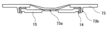
- the valve body 73 as an external terminal, when the battery internal pressure rises and the valve body 73 is broken, a gas discharge path inside the battery can be sufficiently secured.
- an electrode body 19 formed by winding a positive electrode plate 16 and a negative electrode plate 17 via a separator 18 is used.
- the positive electrode plate 16 can be manufactured, for example, as follows. First, the positive electrode active material and the binder are kneaded uniformly in the dispersion medium to prepare a positive electrode mixture slurry. It is preferable to use polyvinylidene fluoride as the binder and N-methylpyrrolidone as the dispersion medium. It is preferable to add a conductive agent such as graphite or carbon black to the positive electrode mixture slurry. This positive electrode mixture slurry is applied on a positive electrode current collector and dried to form a positive electrode mixture layer. In that case, the positive electrode collector exposed part in which the positive mix layer is not formed in a part of the positive electrode collector is provided. Next, the positive electrode mixture layer is compressed to a predetermined thickness with a roller, and the compressed electrode plate is cut into a predetermined dimension. Finally, the positive electrode lead 16a is connected to the exposed portion of the positive electrode current collector to obtain the positive electrode plate 16.
- a lithium transition metal composite oxide capable of inserting and extracting lithium ions can be used.
- the lithium transition metal composite oxide include general formula LiMO 2 (M is at least one of Co, Ni, and Mn), LiMn 2 O 4, and LiFePO 4 . These can be used singly or in combination of two or more, and at least one selected from the group consisting of Al, Ti, Mg, and Zr is added or substituted with a transition metal element It can also be used.
- the negative electrode plate 17 can be manufactured, for example, as follows. First, a negative electrode active material and a binder are kneaded so as to be uniform in a dispersion medium to prepare a negative electrode mixture slurry. It is preferable to use a styrene butadiene (SBR) copolymer as the binder and water as the dispersion medium. It is preferable to add a thickener such as carboxymethylcellulose to the negative electrode mixture slurry. This negative electrode mixture slurry is applied onto a negative electrode current collector and dried to form a negative electrode mixture layer. In that case, the negative electrode collector exposure part in which the negative mix layer is not formed in a part of negative electrode collector is provided. Next, the negative electrode mixture layer is compressed to a predetermined thickness with a roller, and the compressed electrode plate is cut into a predetermined dimension. Finally, the negative electrode lead 17a is connected to the negative electrode current collector exposed portion to obtain the negative electrode plate 17.
- SBR styrene butadiene
- a carbon material or a metal material capable of inserting and extracting lithium ions can be used as the negative electrode active material.
- the carbon material include graphite such as natural graphite and artificial graphite.
- the metal material include silicon and tin, and oxides thereof. The carbon material and the metal material can be used alone or in admixture of two or more.
- a microporous film mainly composed of polyolefin such as polyethylene (PE) or polypropylene (PP) can be used.
- the microporous membrane can be used singly or as a laminate of two or more layers.
- a layer mainly composed of polyethylene (PE) having a low melting point is used as an intermediate layer and polypropylene (PP) having excellent oxidation resistance is used as a surface layer.
- inorganic particles such as aluminum oxide (Al 2 O 3 ), titanium oxide (TiO 2 ), and silicon oxide (SiO 2 ) can be added to the separator 18.
- Such inorganic particles can be carried in the separator and can be applied together with a binder on the separator surface.
- non-aqueous electrolyte a solution obtained by dissolving a lithium salt as an electrolyte salt in a non-aqueous solvent can be used.
- a cyclic carbonate, a chain carbonate, a cyclic carboxylic acid ester and a chain carboxylic acid ester can be used, and it is preferable to use a mixture of two or more.
- the cyclic carbonate include ethylene carbonate (EC), propylene carbonate (PC), and butylene carbonate (BC).
- a cyclic carbonate in which part of hydrogen is substituted with fluorine, such as fluoroethylene carbonate (FEC) can also be used.
- the chain carbonate include dimethyl carbonate (DMC), ethyl methyl carbonate (EMC), diethyl carbonate (DEC), and methyl propyl carbonate (MPC).
- Examples of cyclic carboxylic acid esters include ⁇ -butyrolactone ( ⁇ -BL) and ⁇ -valerolactone ( ⁇ -VL).
- Examples of chain carboxylic acid esters include methyl pivalate, ethyl pivalate, methyl isobutyrate and methyl Pionate is exemplified.
- LiPF 6 , LiBF 4 , LiCF 3 SO 3 , LiN (CF 3 SO 2 ) 2 , LiN (C 2 F 5 SO 2 ) 2 , LiN (CF 3 SO 2 ) (C 4 F 9 SO 2 ) , LiC (CF 3 SO 2 ) 3 , LiC (C 2 F 5 SO 2 ) 3 , LiAsF 6 , LiClO 4 , Li 2 B 10 Cl 10 and Li 2 B 12 Cl 12 are exemplified.
- LiPF 6 is particularly preferable, and the concentration in the nonaqueous electrolytic solution is preferably 0.5 to 2.0 mol / L.
- Other lithium salts such as LiBF 4 may be mixed with LiPF 6 .
- Example 1 (Preparation of sealing body)
- the sealing body 11 described in FIG. 2 was produced as follows.
- the terminal cap 12, the valve body 13, and the metal plate 15 were each formed by pressing a metal plate material into a predetermined shape by pressing.
- the terminal cap 12 was made of iron, and the valve body 13 and the metal plate 15 were made of aluminum.
- the insulating member 14 was produced by punching a polypropylene plate material, which is a thermoplastic resin, into a ring shape, and then thermoforming it so as to have the cross-sectional shape shown in FIG.
- the protrusion 13a and the protrusion 13b were formed in the center part and the outer peripheral part of the valve body 13, respectively. At this stage, the protruding portion 13b protrudes in a direction perpendicular to the flat portion of the valve body 13. As shown in FIG. 3, the protrusion 13b is composed of one annular protrusion. Moreover, the groove-shaped thin part 13c was formed around the projection part 13a. The thin portion 13c becomes a starting point of breakage when the battery internal pressure increases and the valve body 13 functions as a safety valve.
- a thin region was formed in the central portion of the metal plate 15, and a thin portion 15 a having a circular planar shape and a V-shaped cross section was formed in the region.
- This thin portion 15a functions as a current interrupting portion, and the remaining thickness of the thin portion 15a was adjusted so that the operating pressure was 2.5 MPa.
- the metal plate 15 was provided with a vent hole.
- the metal plate 15 produced as described above was fitted to the inner peripheral portion of the skirt portion 14 a of the insulating member 14 so that the insulating member 14 held the metal plate 15.
- the insulating member 14 holding the metal plate 15 is fitted to the inner peripheral portion of the protrusion 13b of the valve body 13, and the metal plate 15 is caulked and fixed by the protrusion 13b by pressing the protrusion 13b in the inner peripheral direction. did.
- the protrusion 13a of the valve body 13 and the metal plate 15 were connected by laser welding.
- the terminal cap 12 was connected on the valve body 13, and the sealing body 11 was produced.
- Preparation of positive electrode plate 95 parts by mass of lithium cobalt composite oxide (LiCoO 2 ) as a positive electrode active material, 2.5 parts by mass of polyvinylidene fluoride (PVdF) as a binder, and 2.5 parts by mass of acetylene black as a conductive agent It mixed so that it might become. This mixture was put into N-methyl 2-pyrrolidone (NMP) as a dispersion medium and kneaded to prepare a positive electrode mixture slurry. This positive electrode mixture slurry was applied to both surfaces of a positive electrode current collector made of aluminum foil and dried to form a positive electrode mixture layer.
- NMP N-methyl 2-pyrrolidone
- the positive electrode collector exposed part in which the positive mix layer was not formed in a part of the positive electrode collector was provided.
- the positive electrode mixture layer was compressed to a predetermined thickness with a roller, and the compressed electrode plate was cut into predetermined dimensions.
- a positive electrode plate 16 was fabricated by connecting an aluminum positive electrode lead 16a to the exposed portion of the positive electrode current collector.
- the mixture was mixed so that graphite as a negative electrode active material was 95 parts by mass, styrene butadiene rubber (SBR) as a binder was 3 parts by mass, and carboxymethyl cellulose (CMC) as a thickener was 2 parts by mass.
- SBR styrene butadiene rubber
- CMC carboxymethyl cellulose
- the mixture was put into water as a dispersion medium and kneaded to prepare a negative electrode mixture slurry.
- This negative electrode mixture slurry was applied to both sides of a negative electrode current collector made of copper foil and dried to form a negative electrode mixture layer. In that case, the negative electrode collector exposed part in which the negative electrode mixture layer was not formed was provided in a part of the negative electrode current collector.
- the negative electrode mixture layer was compressed with a roller to a predetermined thickness, and the compressed electrode plate was cut into a predetermined dimension. Finally, a negative electrode lead 17a made of nickel was connected to the exposed portion of the negative electrode current collector to produce a negative electrode plate 17.
- the positive electrode plate 16 and the negative electrode plate 17 were wound through a separator 18 made of a microporous polyolefin film to produce an electrode body 19.
- Ethylene carbonate (EC), dimethyl carbonate (DMC), and ethyl methyl carbonate (EMC) were mixed to prepare a non-aqueous solvent.
- LiPF 6 lithium hexafluorophosphate
- this non-aqueous solvent lithium hexafluorophosphate (LiPF 6 ) as an electrolyte salt was dissolved to a concentration of 1 mol / L to prepare a non-aqueous electrolyte.
- the lower insulating plate 20 is disposed below the electrode body 19, and the electrode body 19 is inserted into a bottomed cylindrical outer can 23.
- the negative electrode lead 17a was connected to the bottom of the outer can 23 by resistance welding.
- the upper insulating plate 21 is disposed on the upper part of the electrode body 19, and a U-shaped groove portion having a width of 1.0 mm and a depth of 1.5 mm is formed in the vicinity of the opening of the outer can 23 by plastic working in the circumferential direction. Formed.
- the positive electrode lead 16 a was connected to the metal plate 15, and the sealing body 11 was caulked and fixed to the groove formed in the outer can 23 via the gasket 22, thereby producing the nonaqueous electrolyte secondary battery 10.
- Example 2 As shown in FIG. 4, the nonaqueous electrolyte secondary battery according to Example 2 was used in the same manner as in Example 1 except that the valve body 43 having the protrusions 43 b in which a plurality of protrusions were annularly and intermittently arranged was used. Produced.
- Example 3 As shown in FIG. 5, a non-aqueous electrolyte secondary battery according to Example 3 was fabricated in the same manner as in Example 1 except that the valve element 53 having the protruding portion 53b having a tapered cross section was used.
- Example 4 As shown in FIG. 6, a nonaqueous electrolyte secondary battery according to Example 4 was produced in the same manner as in Example 1 except that the valve body 63 having the protrusion 63b having a curved cross-sectional shape was used.
- Example 5 As shown in FIG. 7, the sealing body which consists of the valve body 73, the insulating member 14, and the metal plate 15 was produced as follows. Since this sealing body does not use a terminal cap, the valve body 73 functions as an external terminal. A protrusion 73a and a protrusion 73b are provided at the center and the outer periphery of the valve body 73, respectively. A thin portion was provided around the protrusion 73a so that the valve body 73 can be deformed by receiving the internal pressure of the battery. Further, a thick portion that functions as an external terminal is provided around the thin portion. The protrusion 73b has the same shape as the protrusion 13b according to the first embodiment. A nonaqueous electrolyte secondary battery according to Example 5 was produced in the same manner as in Example 1 except that the thus produced sealing body was used.
- the sealing body 81 which consists of the terminal cap 82, the valve body 83, the insulating member 84, and the metal plate 85 was produced as follows.
- the terminal cap 82 and the metal plate 85 were produced in the same manner as in Example 1.
- the valve body 83 was manufactured by pressing an aluminum plate material, but the protrusion 83b was inclined toward the center when the valve body 83 was manufactured.
- the insulating member 84 was produced by punching a plate made of polypropylene resin into a ring shape and thermoforming the cross-sectional shape into a Z-shape.
- a nonaqueous electrolyte secondary battery according to a comparative example was produced in the same manner as in Example 1 except that the sealing body 81 was used.
- Ultrasonic waves were applied to the sealing bodies of the batteries according to Examples 1 to 5 and the comparative example.
- the ultrasonic wave was applied to the sealing body in a state where an aluminum lead was placed on the sealing body and the aluminum lead was pressurized with a horn.
- the excitation time was set to be longer than the time required for welding the aluminum lead so that the solid difference due to the ultrasonic wave appears clearly.
- After the ultrasonic vibration it was confirmed whether or not the connecting portion between the valve body and the metal plate inside the sealing body was broken.
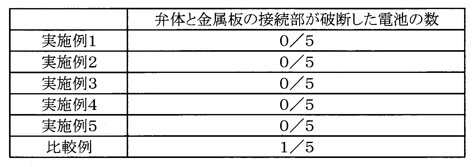
- Each example and comparative example were tested using five batteries. The results are shown in Table 1.
- the present invention it is possible to provide a cylindrical battery including a sealing body that maintains its function even when external vibration such as ultrasonic waves is applied. Therefore, the present invention can greatly contribute to the improvement of the quality of the cylindrical battery. Furthermore, according to the present invention, it is possible to perform inter-battery connection by wire bonding using a cylindrical battery, and therefore the present invention can improve the degree of freedom of design of the assembled battery.
Landscapes
- Chemical & Material Sciences (AREA)
- Chemical Kinetics & Catalysis (AREA)
- Electrochemistry (AREA)
- General Chemical & Material Sciences (AREA)
- Engineering & Computer Science (AREA)
- Manufacturing & Machinery (AREA)
- Connection Of Batteries Or Terminals (AREA)
- Sealing Battery Cases Or Jackets (AREA)
- Secondary Cells (AREA)
- Gas Exhaust Devices For Batteries (AREA)
Abstract
Description
封口体が、環状の突起部を有する弁体、弁体の突起部の内周に配置されるとともにスカート部を有する絶縁部材、及び絶縁部材のスカート部の内周部に配置されるとともに弁体の中央部に接続される金属板を有し、
金属板が絶縁部材を介して弁体の突起部によってかしめ固定されていることを特徴としている。
(1)環状の突起部を有する弁体と、金属板と、スカート部を有する絶縁部材とを準備するステップ
(2)絶縁部材のスカート部の内側に金属板を嵌め合わせるステップ
(3)弁体の突起部の内側に絶縁部材を嵌め合わせるステップ
(4)弁体の突起部が絶縁板を介して金属板を固定するように弁体の突起部をプレスするステップ
(封口体の作製)
図2に記載された封口体11を次のように作製した。端子キャップ12、弁体13、及び金属板15はそれぞれ金属製の板材をプレス加工により所定の形状に成型した。端子キャップ12には鉄を、弁体13及び金属板15にはアルミニウムを用いた。絶縁部材14は、熱可塑性樹脂であるポリプロピレン製の板材を環状に打ち抜いた後、図2に示す断面形状となるように熱成型することにより作製した。
正極活物質としてのリチウムコバルト複合酸化物(LiCoO2)が95質量部、結着剤としてのポリフッ化ビニリデン(PVdF)が2.5質量部、導電剤としてのアセチレンブラックが2.5重量部となるように混合した。この混合物を分散媒としてのN-メチル2-ピロリドン(NMP)中に投入、混練して正極合剤スラリーを調製した。この正極合剤スラリーをアルミニウム箔からなる正極集電体の両面に塗布、乾燥して正極合剤層を形成した。その際、正極集電体の一部に正極合剤層が形成されていない正極集電体露出部を設けた。次に、正極合剤層をローラーで所定厚みに圧縮し、圧縮後の極板を所定寸法に切断した。最後に、正極集電体露出部にアルミニウム製の正極リード16aを接続して正極板16を作製した。
負極活物質としての黒鉛が95質量部、結着剤としてのスチレンブタジエンゴム(SBR)が3質量部、増粘剤としてのカルボキシメチルセルロース(CMC)が2重量部となるように混合した。その混合物を分散媒としての水中に投入し、混練して負極合剤スラリーを調製した。この負極合剤スラリーを銅箔からなる負極集電体の両面に塗布、乾燥して負極合剤層を形成した。その際、負極集電体の一部に負極合剤層が形成されていない負極集電体露出部を設けた。次に、負極合剤層をローラーで所定厚みに圧縮し、圧縮後の極板を所定寸法に切断した。最後に、負極集電体露出部にニッケル製の負極リード17aを接続して負極板17を作製した。
正極板16と負極板17を、微多孔製ポリオレフィン膜からなるセパレータ18を介して巻回して電極体19を作製した。
エチレンカーボネート(EC)、ジメチルカーボネート(DMC)、及びエチルメチルカーボネート(EMC)を混合して非水溶媒を調製した。この非水溶媒に電解質塩としてのヘキサフルオロリン酸リチウム(LiPF6)を1mol/Lの濃度になるように溶解して非水電解液を調製した。
図1に示すように、電極体19の下部に下部絶縁板20を配置し、電極体19を有底円筒状の外装缶23へ挿入した。負極リード17aは外装缶23の底部に抵抗溶接により接続した。次に、電極体19の上部に上部絶縁板21を配置し、外装缶23の開口部の近傍に幅1.0mm、深さ1.5mmのU字状の溝部を円周方向に塑性加工によって形成した。そして、正極リード16aを金属板15に接続し、外装缶23に形成された溝部にガスケット22を介して封口体11をかしめ固定することにより非水電解液二次電池10を作製した。
図4に示すように複数の突起を環状かつ断続的に配置した突起部43bを有する弁体43を用いたこと以外は実施例1と同様に実施例2に係る非水電解液二次電池を作製した。
図5に示すように断面形状をテーパー形状とした突起部53bを有する弁体53を用いたこと以外は実施例1と同様にして実施例3に係る非水電解液二次電池を作製した。
図6に示すように断面形状を曲線状とした突起部63bを有する弁体63を用いたこと以外は実施例1と同様にして実施例4に係る非水電解液二次電池を作製した。
図7に示すように、弁体73、絶縁部材14、及び金属板15からなる封口体を次のように作製した。この封口体は端子キャップを用いていないため、弁体73が外部端子として機能する。弁体73の中央部と外周部のそれぞれに突起部73aと突起部73bを設けた。弁体73が電池内圧を受けて変形することができるように突起部73aの周囲に厚みが薄い部分を設けた。さらにその厚みが薄い部分の周囲に外部端子として機能する厚みが厚い部分を設けた。突起部73bは実施例1に係る突起部13bと同一の形状とした。このように作製した封口体を用いたこと以外は実施例1と同様にして実施例5に係る非水電解液二次電池を作製した。
図8に示すように、端子キャップ82、弁体83、絶縁部材84、及び金属板85からなる封口体81を次のように作製した。端子キャップ82と金属板85は実施例1と同様な方法で作製した。弁体83はアルミニウム製の板材をプレス加工して作製したが、突起部83bは弁体83の作製時に中央側へ傾斜させた。絶縁部材84はポリプロピレン樹脂製の板材を環状に打ち抜き、断面形状がZ字状になるように熱成型して作製した。そして、金属板15を絶縁部材14の内側に嵌め合わせて、その絶縁部材14を弁体83の突起部83bの内側に嵌め合わせた。最後に、弁体の中央部の突起部83aを金属板85に接続し、端子キャップ82を弁体83上に接続して封口体81を作製した。封口体81を用いたこと以外は実施例1と同様にして比較例に係る非水電解液二次電池を作製した。
実施例1~5及び比較例に係る各電池の封口体に超音波を加振した。封口体への超音波の加振は、封口体上にアルミニウムリードを配置し、ホーンでそのアルミニウムリードを加圧した状態で行った。ただし超音波による影響の固体差が明確に現れるように、アルミニウムリードを溶接するために必要な時間よりも加振時間を長めに設定した。超音波の加振後、封口体内部の弁体と金属板の接続部が破断していないかを確認した。各実施例及び比較例についてそれぞれ5個の電池を用いて試験を行った。その結果を表1に示す。
11 封口体
12 端子キャップ
13 弁体
13b 突起部
13c 薄肉部
14 絶縁部材
14a スカート部
15 金属板
15a 薄肉部
16 正極板
17 負極板
18 セパレータ
19 電極体
23 外装缶
Claims (5)
- 正極板と負極板がセパレータを介して巻回された電極体と、電解液と、有底円筒状の外装缶と、前記外装缶の開口部にガスケットを介してかしめ固定された封口体と、を備える円筒形電池において、
前記封口体が、環状の突起部を有する弁体、前記弁体の突起部の内周に配置されるとともにスカート部を有する絶縁部材、及び前記絶縁部材のスカート部の内周部に配置されるとともに前記弁体の中央部に接続される金属板を有し、
前記金属板が、前記絶縁部材を介して前記弁体の突起部によってかしめ固定されている、
円筒形電池。 - 前記スカート部の先端部が前記金属板の表面に沿って内周側へ折り曲げられている請求項1に記載の円筒形電池。
- 前記突起部がテーパー形状を有する請求項1又は2に記載の円筒形電池。
- 前記突起部が環状の一つの突起、又は環状かつ断続的に設けられた複数の突起で形成されている請求項1から3のいずれかに記載の円筒形電池。
- 電極体と電解液を収容する有底円筒状の外装缶の開口部が封口体でかしめ固定された円筒形電池の製造方法であって、
環状の突起部を有する弁体と、金属板と、スカート部を有する絶縁部材とを準備するステップと、
前記絶縁部材のスカート部の内側に前記金属板を嵌め合わせるステップと、
前記弁体の突起部の内側に前記絶縁部材を嵌め合わせるステップと、
前記弁体の突起部が前記絶縁部材を介して前記金属板を固定するように前記弁体の突起部を中心側にプレスするステップと、
を備える円筒形電池の製造方法。
Priority Applications (3)
| Application Number | Priority Date | Filing Date | Title |
|---|---|---|---|
| JP2017509230A JP6773027B2 (ja) | 2015-03-27 | 2016-03-10 | 円筒形電池及びその製造方法 |
| CN201680014392.4A CN107408664B (zh) | 2015-03-27 | 2016-03-10 | 圆筒形电池及其制造方法 |
| US15/554,479 US10601002B2 (en) | 2015-03-27 | 2016-03-10 | Cylindrical battery and method for producing the same |
Applications Claiming Priority (2)
| Application Number | Priority Date | Filing Date | Title |
|---|---|---|---|
| JP2015-066233 | 2015-03-27 | ||
| JP2015066233 | 2015-03-27 |
Publications (1)
| Publication Number | Publication Date |
|---|---|
| WO2016157748A1 true WO2016157748A1 (ja) | 2016-10-06 |
Family
ID=57004863
Family Applications (1)
| Application Number | Title | Priority Date | Filing Date |
|---|---|---|---|
| PCT/JP2016/001338 Ceased WO2016157748A1 (ja) | 2015-03-27 | 2016-03-10 | 円筒形電池及びその製造方法 |
Country Status (4)
| Country | Link |
|---|---|
| US (1) | US10601002B2 (ja) |
| JP (1) | JP6773027B2 (ja) |
| CN (1) | CN107408664B (ja) |
| WO (1) | WO2016157748A1 (ja) |
Cited By (8)
| Publication number | Priority date | Publication date | Assignee | Title |
|---|---|---|---|---|
| WO2019082712A1 (ja) * | 2017-10-23 | 2019-05-02 | 三洋電機株式会社 | 円筒形電池 |
| CN110945685A (zh) * | 2017-07-31 | 2020-03-31 | 松下知识产权经营株式会社 | 圆筒形电池 |
| WO2021106729A1 (ja) | 2019-11-29 | 2021-06-03 | 三洋電機株式会社 | 密閉電池 |
| WO2021124995A1 (ja) | 2019-12-18 | 2021-06-24 | 三洋電機株式会社 | 円筒形電池 |
| JPWO2021145247A1 (ja) * | 2020-01-17 | 2021-07-22 | ||
| WO2021200737A1 (ja) * | 2020-03-31 | 2021-10-07 | パナソニックIpマネジメント株式会社 | 封口体および電池 |
| WO2023063009A1 (ja) * | 2021-10-11 | 2023-04-20 | 株式会社村田製作所 | 二次電池 |
| WO2025204681A1 (ja) * | 2024-03-29 | 2025-10-02 | パナソニックIpマネジメント株式会社 | 円筒形電池 |
Families Citing this family (8)
| Publication number | Priority date | Publication date | Assignee | Title |
|---|---|---|---|---|
| WO2019117339A1 (ko) * | 2017-12-13 | 2019-06-20 | 삼성에스디아이(주) | 원통형 리튬 이온 이차 전지 |
| US20190296273A1 (en) * | 2018-03-23 | 2019-09-26 | Sf Motors, Inc. | Battery cell for electric vehicle battery pack |
| HUE065171T2 (hu) * | 2018-07-13 | 2024-05-28 | Hydro Quebec | Biztonsági szellõzõegység akkumulátorházhoz |
| JP7379380B2 (ja) * | 2018-12-28 | 2023-11-14 | パナソニックエナジー株式会社 | 密閉電池 |
| US11699834B2 (en) * | 2019-01-18 | 2023-07-11 | Sanyo Electric Co., Ltd. | Sealed battery |
| CN109560319B (zh) * | 2019-01-23 | 2025-04-01 | 银隆新能源股份有限公司 | 连接辅助治具及圆柱电池加工线 |
| CN112448097B (zh) * | 2019-09-04 | 2022-11-04 | 东莞新能源科技有限公司 | 防爆阀及电池组件 |
| KR20240132869A (ko) * | 2023-02-27 | 2024-09-04 | 삼성에스디아이 주식회사 | 이차 전지 |
Citations (3)
| Publication number | Priority date | Publication date | Assignee | Title |
|---|---|---|---|---|
| JPH087866A (ja) * | 1994-06-24 | 1996-01-12 | Fuji Elelctrochem Co Ltd | 防爆安全装置を備えた電池とその製造方法 |
| JPH10154530A (ja) * | 1996-11-21 | 1998-06-09 | Ngk Insulators Ltd | リチウム二次電池 |
| WO2014097586A1 (ja) * | 2012-12-19 | 2014-06-26 | 三洋電機株式会社 | 円筒形二次電池及びその製造方法 |
Family Cites Families (10)
| Publication number | Priority date | Publication date | Assignee | Title |
|---|---|---|---|---|
| KR20060097603A (ko) * | 2005-03-09 | 2006-09-14 | 산요덴키가부시키가이샤 | 전지 및 그 제조 방법 |
| KR100786875B1 (ko) | 2006-10-20 | 2007-12-20 | 삼성에스디아이 주식회사 | 전지 모듈 |
| KR100796695B1 (ko) * | 2007-01-19 | 2008-01-21 | 삼성에스디아이 주식회사 | 이차 전지 및 이차 전지의 제조방법 |
| JP2009059572A (ja) * | 2007-08-31 | 2009-03-19 | Panasonic Corp | 非水電解質二次電池 |
| US20100233524A1 (en) * | 2008-05-28 | 2010-09-16 | Yasuhiko Hina | Cylindrical non-aqueous electrolyte secondary battery |
| US8241772B2 (en) | 2009-06-12 | 2012-08-14 | Tesla Motors, Inc. | Integrated battery pressure relief and terminal isolation system |
| KR20120049840A (ko) * | 2009-08-05 | 2012-05-17 | 파나소닉 주식회사 | 밀폐형 전지 및 그 제조 방법 |
| WO2012017586A1 (ja) * | 2010-08-06 | 2012-02-09 | パナソニック株式会社 | 電池モジュール |
| US9088031B2 (en) * | 2010-11-05 | 2015-07-21 | Panasonic Intellectual Property Management Co., Ltd. | Battery module |
| US9337454B2 (en) * | 2010-12-03 | 2016-05-10 | Panasonic Intellectual Property Management Co., Ltd. | Battery pack including gas absorption portion |
-
2016
- 2016-03-10 WO PCT/JP2016/001338 patent/WO2016157748A1/ja not_active Ceased
- 2016-03-10 JP JP2017509230A patent/JP6773027B2/ja active Active
- 2016-03-10 CN CN201680014392.4A patent/CN107408664B/zh active Active
- 2016-03-10 US US15/554,479 patent/US10601002B2/en active Active
Patent Citations (3)
| Publication number | Priority date | Publication date | Assignee | Title |
|---|---|---|---|---|
| JPH087866A (ja) * | 1994-06-24 | 1996-01-12 | Fuji Elelctrochem Co Ltd | 防爆安全装置を備えた電池とその製造方法 |
| JPH10154530A (ja) * | 1996-11-21 | 1998-06-09 | Ngk Insulators Ltd | リチウム二次電池 |
| WO2014097586A1 (ja) * | 2012-12-19 | 2014-06-26 | 三洋電機株式会社 | 円筒形二次電池及びその製造方法 |
Cited By (20)
| Publication number | Priority date | Publication date | Assignee | Title |
|---|---|---|---|---|
| CN110945685A (zh) * | 2017-07-31 | 2020-03-31 | 松下知识产权经营株式会社 | 圆筒形电池 |
| US11831032B2 (en) | 2017-07-31 | 2023-11-28 | Panasonic Intellectual Property Management Co., Ltd. | Cylindrical battery |
| US11251458B2 (en) | 2017-10-23 | 2022-02-15 | Sanyo Electric Co., Ltd. | Cylindrical batteries |
| CN111247660A (zh) * | 2017-10-23 | 2020-06-05 | 三洋电机株式会社 | 圆筒形电池 |
| JPWO2019082712A1 (ja) * | 2017-10-23 | 2020-11-12 | 三洋電機株式会社 | 円筒形電池 |
| WO2019082712A1 (ja) * | 2017-10-23 | 2019-05-02 | 三洋電機株式会社 | 円筒形電池 |
| JP7191845B2 (ja) | 2017-10-23 | 2022-12-19 | 三洋電機株式会社 | 円筒形電池 |
| CN111247660B (zh) * | 2017-10-23 | 2022-08-02 | 三洋电机株式会社 | 圆筒形电池 |
| WO2021106729A1 (ja) | 2019-11-29 | 2021-06-03 | 三洋電機株式会社 | 密閉電池 |
| WO2021124995A1 (ja) | 2019-12-18 | 2021-06-24 | 三洋電機株式会社 | 円筒形電池 |
| US12347878B2 (en) | 2019-12-18 | 2025-07-01 | Panasonic Energy Co., Ltd. | Cylindrical battery |
| JPWO2021145247A1 (ja) * | 2020-01-17 | 2021-07-22 | ||
| JP7669293B2 (ja) | 2020-01-17 | 2025-04-28 | パナソニックエナジー株式会社 | 密閉電池 |
| JPWO2021200737A1 (ja) * | 2020-03-31 | 2021-10-07 | ||
| CN115088117A (zh) * | 2020-03-31 | 2022-09-20 | 松下知识产权经营株式会社 | 封口体以及电池 |
| WO2021200737A1 (ja) * | 2020-03-31 | 2021-10-07 | パナソニックIpマネジメント株式会社 | 封口体および電池 |
| CN115088117B (zh) * | 2020-03-31 | 2024-08-27 | 松下知识产权经营株式会社 | 封口体以及电池 |
| JP7678526B2 (ja) | 2020-03-31 | 2025-05-16 | パナソニックIpマネジメント株式会社 | 封口体および電池 |
| WO2023063009A1 (ja) * | 2021-10-11 | 2023-04-20 | 株式会社村田製作所 | 二次電池 |
| WO2025204681A1 (ja) * | 2024-03-29 | 2025-10-02 | パナソニックIpマネジメント株式会社 | 円筒形電池 |
Also Published As
| Publication number | Publication date |
|---|---|
| CN107408664B (zh) | 2020-11-27 |
| JPWO2016157748A1 (ja) | 2018-01-18 |
| CN107408664A (zh) | 2017-11-28 |
| US10601002B2 (en) | 2020-03-24 |
| JP6773027B2 (ja) | 2020-10-21 |
| US20180047949A1 (en) | 2018-02-15 |
Similar Documents
| Publication | Publication Date | Title |
|---|---|---|
| JP6773027B2 (ja) | 円筒形電池及びその製造方法 | |
| JP7006683B2 (ja) | 円筒形電池 | |
| JP6662377B2 (ja) | 円筒形電池 | |
| CN111247660B (zh) | 圆筒形电池 | |
| US10224533B2 (en) | Secondary battery comprising current interrupt device | |
| JP6477334B2 (ja) | 円筒形電池 | |
| US10461304B2 (en) | Cylindrical battery | |
| JP7225110B2 (ja) | 円筒形電池 | |
| CN107431179B (zh) | 圆筒形电池 | |
| EP3905418A1 (en) | Cylindrical battery | |
| JPWO2012147782A1 (ja) | 密閉型電池及びその製造方法 | |
| JPWO2014097586A1 (ja) | 円筒形二次電池及びその製造方法 | |
| JPWO2020137716A1 (ja) | 円筒形電池 | |
| JP4374861B2 (ja) | 角形リチウム二次電池 | |
| JP2020053262A (ja) | 電池リード接続体及び電池モジュール |
Legal Events
| Date | Code | Title | Description |
|---|---|---|---|
| 121 | Ep: the epo has been informed by wipo that ep was designated in this application |
Ref document number: 16771642 Country of ref document: EP Kind code of ref document: A1 |
|
| WWE | Wipo information: entry into national phase |
Ref document number: 15554479 Country of ref document: US |
|
| ENP | Entry into the national phase |
Ref document number: 2017509230 Country of ref document: JP Kind code of ref document: A |
|
| NENP | Non-entry into the national phase |
Ref country code: DE |
|
| 122 | Ep: pct application non-entry in european phase |
Ref document number: 16771642 Country of ref document: EP Kind code of ref document: A1 |