WO2016157655A1 - 送液ポンプ管理システム - Google Patents
送液ポンプ管理システム Download PDFInfo
- Publication number
- WO2016157655A1 WO2016157655A1 PCT/JP2015/086030 JP2015086030W WO2016157655A1 WO 2016157655 A1 WO2016157655 A1 WO 2016157655A1 JP 2015086030 W JP2015086030 W JP 2015086030W WO 2016157655 A1 WO2016157655 A1 WO 2016157655A1
- Authority
- WO
- WIPO (PCT)
- Prior art keywords
- pump
- information
- liquid
- drug
- administration
- Prior art date
Links
Images


Classifications
-
- A—HUMAN NECESSITIES
- A61—MEDICAL OR VETERINARY SCIENCE; HYGIENE
- A61M—DEVICES FOR INTRODUCING MEDIA INTO, OR ONTO, THE BODY; DEVICES FOR TRANSDUCING BODY MEDIA OR FOR TAKING MEDIA FROM THE BODY; DEVICES FOR PRODUCING OR ENDING SLEEP OR STUPOR
- A61M5/00—Devices for bringing media into the body in a subcutaneous, intra-vascular or intramuscular way; Accessories therefor, e.g. filling or cleaning devices, arm-rests
- A61M5/14—Infusion devices, e.g. infusing by gravity; Blood infusion; Accessories therefor
- A61M5/142—Pressure infusion, e.g. using pumps
-
- A—HUMAN NECESSITIES
- A61—MEDICAL OR VETERINARY SCIENCE; HYGIENE
- A61M—DEVICES FOR INTRODUCING MEDIA INTO, OR ONTO, THE BODY; DEVICES FOR TRANSDUCING BODY MEDIA OR FOR TAKING MEDIA FROM THE BODY; DEVICES FOR PRODUCING OR ENDING SLEEP OR STUPOR
- A61M5/00—Devices for bringing media into the body in a subcutaneous, intra-vascular or intramuscular way; Accessories therefor, e.g. filling or cleaning devices, arm-rests
- A61M5/14—Infusion devices, e.g. infusing by gravity; Blood infusion; Accessories therefor
- A61M5/168—Means for controlling media flow to the body or for metering media to the body, e.g. drip meters, counters ; Monitoring media flow to the body
Definitions
- the present invention relates to a liquid feed pump management system used when a medicine is administered to a patient by using a plurality of syringe pumps, for example, syringe pumps.
- an object of the present invention is to provide a liquid feed pump management system capable of reliably executing a correct administration method for each liquid feed pump such as each syringe pump mounted on a rack device.
- the object is to provide a liquid feed pump that administers a medicine to a subject, a liquid feed pump rack device having a plurality of liquid feed pump mounting portions on which the liquid feed pump can be arranged, and the liquid feed.
- a liquid delivery pump management system comprising: a management device that is communicably connected to the pump rack device, wherein the liquid delivery pump includes first drug type information that is drug type information and the first drug information.
- Storage unit storing corresponding administration execution process information which is information on at least one administration method corresponding to the liquid delivery pump rack device or the management device is associated with each liquid delivery pump mounting unit.
- the second medicine type information which is the kind information of the medicine, and the first medicine information of the liquid feeding pump to be attached to the liquid feeding pump attachment portion, and the liquid feeding pump to which the liquid feeding pump is attached Said second corresponding to the part
- the drug type information is compared, and execution of the drug according to the corresponding administration execution information corresponding to the first drug type information that does not match the second drug type information is restricted. Achieved by liquid pump management system.
- medical agent information for example, chemical
- worn the liquid feeding pump with which a liquid feeding pump mounting part is mounted
- the second drug type information corresponding to the mounting unit is compared, and the corresponding administration corresponding to the first drug type information that does not match the second drug type information
- limits performing administration according to execution information for example, execution models, such as a Marsh model).
- the liquid delivery pump stores first corresponding administration execution process information (for example, the Marsh model) that is information on at least one administration method corresponding to the first agent type information that is the agent type information.
- administration of is automatically and definitely performed.
- the corresponding administration execution process information of the liquid delivery pump is first correspondence administration execution process information
- the liquid delivery pump rack device or the management device is associated with each of the delivery pump mounting portions.
- the second corresponding administration execution process information which is information related to the administration method, includes the first corresponding administration execution process information of the liquid feeding pump mounted on the liquid feeding pump mounting portion, and the liquid pump mounted Comparing the second corresponding administration execution process information corresponding to the liquid delivery pump mounting unit, and executing the administration of the medicine according to the first corresponding administration execution information that does not match the second corresponding administration execution process information, It is characterized by limiting.
- a message to that effect is output.
- the liquid feeding pump is configured to provide the subject's biological information necessary for the execution of the corresponding administration execution step.
- the said structure since it becomes the structure which provides the liquid information of the said subject required for execution of a corresponding
- the agent is an anesthetic-related agent.
- the drug is an anesthetic-related drug. Since an anesthetic produces an extremely serious situation if the administration method for each type is mistaken, the present invention can reliably prevent the occurrence of such a serious danger.
- the object is to provide a liquid feed pump that administers a medicine to a subject, a liquid feed pump rack device having a plurality of liquid feed pump mounting portions on which the liquid feed pump can be arranged, and the liquid feed.
- a liquid feed pump management system comprising a management device communicably connected to the pump rack device, wherein the liquid feed pump stores a first corresponding administration execution process information that is information relating to an administration method.
- the liquid delivery pump rack device or the management device has a second corresponding administration execution process information that is information relating to an administration method corresponding to each of the delivery pump mounting portions, and the delivery pump Comparing the first corresponding administration execution process information of the liquid feeding pump attached to the attachment part with the second corresponding administration execution process information corresponding to the liquid delivery pump attaching part to which the liquid pump is attached;
- the second corresponding throw That in accordance with the first correspondence administration execution information that does not match the execution process information to perform the administration of the medicament is accomplished by feeding pump management system and limits.
- liquid feeding pump management system capable of reliably executing a correct administration method for each liquid feeding pump such as each syringe pump mounted on a rack device. Can do.
- FIG.1 It is the schematic which shows the medical pump system which is the liquid-feeding pump management system concerning embodiment of this invention, for example.
- FIG.2 shows the main structures of the 2nd syringe pump side various information storage part of FIG.
- FIG. 10 is a schematic diagram illustrating a main configuration of a rack-mounted medicine storage unit in FIG. 9. It is a schematic flowchart which shows the main operation examples etc. of the medical pump system concerning this Embodiment. It is another schematic flowchart which shows the main operation examples etc. of the medical pump system concerning this Embodiment. It is another schematic flowchart which shows the main operation examples etc. of the medical pump system concerning this Embodiment. It is another schematic flowchart which shows the main operation examples etc. of the medical pump system concerning this Embodiment. It is another schematic flowchart which shows the main operation examples etc. of the medical pump system concerning this Embodiment. It is another schematic flowchart which shows the main operation examples etc. etc.
- FIG. 1 is a schematic view showing, for example, a medical pump system 1 which is a liquid delivery pump management system according to an embodiment of the present invention.
- the medical pump system 1 includes, for example, a syringe pump 100a, a syringe pump 100b, and a syringe pump 100c that are a plurality of, for example, three liquid feeding pumps.
- the syringe pump 100a and the like are configured to be mounted on, for example, a rack device 200 that is a liquid pump rack device.
- FIG. 2 is a schematic perspective view showing the main configuration of the rack apparatus 200 of FIG.
- the rack apparatus 200 includes, for example, an upper mounting section 201a, a middle mounting section 201b, and a lower mounting section 201c, which are liquid feed pump mounting sections to which syringe pumps 100a and 100b 100c can be mounted, respectively. is doing.
- the upper mounting portion 201a, the middle mounting portion 201b, and the lower mounting portion 201c are provided with an upper mounting portion terminal 203a, a middle mounting portion terminal 203b, and a lower mounting portion terminal 203c, respectively. These are connected to syringe pumps 100a, 100b, and 100c that are mounted as shown in FIG. 1, so that they can communicate with each other.
- the rack connection terminal 101 and the upper mounting portion terminal 203a which are arranged in a syringe pump 100a, which will be described later, are connected to each other, so that they can communicate with each other by infrared communication or the like. Yes.
- the rack device 200 has a communication box 202 and is connected to a hospital management server 300 that is a management device arranged in a hospital, for example, so as to be communicable.
- FIG. 3 is a schematic diagram showing a main configuration of the syringe pump 100a and the like shown in FIG. Since the syringe pumps 100b and 100c have the same configuration as the syringe pump 100a, description thereof is omitted.
- the syringe pump 100a has a syringe 108 filled with a medicine, for example, a medicine, and the syringe pusher 102 moves in the direction of arrow T in FIG. 3 to press the medicine in the syringe 108.
- the liquid is accurately fed to the subject, for example, a patient via the tube 103 and the indwelling needle 104.
- the syringe pump 100a has a syringe pump side display unit 105 and an operation panel unit 106 on the right side in the drawing.
- the operation panel unit 106 includes a power ON / OFF button 106a, an operation indicator 106b, a fast-forward switch button 106c, a start switch button 106d, a stop switch button 106e, a menu selection button 106f, and the like.
- the rack apparatus 200, syringe pump 100a, and the like shown in FIG. 1 and the hospital management server 300 have a computer.
- the computer is a CPU (Central Processing Unit), a RAM (Random Access Memory), a ROM (Read Only Memory), not shown. Etc., and these are connected via a bus.
- CPU Central Processing Unit
- RAM Random Access Memory
- ROM Read Only Memory
- FIG. 4 is a schematic block diagram showing the main configuration of the syringe pump 100a of FIGS.
- the syringe pump 100 a includes a “syringe pump control unit 10”, and the syringe pump control unit 110 performs determination / control of the entire syringe pump, and includes the above-described syringe pump side display unit 105,
- the "first syringe pump side various information storage unit 120" and the "second syringe pump side various information storage unit 130" are also controlled. Yes.
- FIG. 10 the syringe pump control unit 10
- the syringe pump control unit 110 performs determination / control of the entire syringe pump, and includes the above-described syringe pump side display unit 105.
- the "first syringe pump side various information storage unit 120" and the "second syringe pump side various information storage unit 130" are also controlled. Yes.
- FIG. 1 the "first syring
- FIG. 5 is a schematic block diagram showing the main configuration of the first syringe pump side various information storage unit 120 of FIG. 4, and FIG. 6 shows the main configuration of the second syringe pump side various information storage unit 130 of FIG. It is a schematic block diagram which shows a structure. The contents of each block in FIGS. 5 and 6 will be described later.
- FIG. 7 is a schematic block diagram showing a main configuration of the rack apparatus 200 shown in FIGS. 1 and 2.
- the rack apparatus 200 includes a “rack control unit 210”, and the rack control unit 210 communicates with the hospital management server 300 and the syringe pump 100 a of FIG. 1 disposed in the communication box 202.
- the “rack side communication device 204” for performing various operations, the “rack side display unit 205” for displaying various information, the “rack side various information input unit 206” such as a keyboard for inputting various information, and the like are controlled.
- the rack control unit 210 also controls the above-described upper mounting terminal 203a, middle mounting terminal 203b, lower mounting terminal 203c, and the like. Furthermore, the rack control unit 210 also controls the “rack-side various information storage unit 220” in FIG.
- FIG. 8 is a schematic block diagram showing the main configuration of the rack-side various information storage unit 220. These contents will be described later.
- FIG. 9 is a schematic block diagram showing the main configuration of the hospital management server 300.
- the hospital management server 300 includes a “server control unit 301”.
- the server control unit 301 includes a “server side communication device 302” for communicating with the rack device 200 and the like illustrated in FIG.
- the “server-side display device 303” for displaying information
- the “server-side various information input device 304” such as a keyboard for inputting various information
- the server control unit 301 also controls a “rack mounting medicine storage unit 307”, an “input staff information storage unit 308”, and a “staff information confirmation unit (program) 309”, which will be described later.
- FIG. 10 is a schematic diagram showing the main configuration of the rack-mounted medicine storage unit 307 of FIG.
- FIGS. 11 to 18 are schematic flowcharts showing main operation examples and the like of the medical pump system 1 according to the present embodiment. Hereafter, each operation
- the drug (medicine solution) of the present embodiment is, for example, an anesthetic, and the drug solution is an anesthetic-related drug solution, for example, “sedative”, “analgesic”, and “muscle relaxant”, respectively, different syringe pumps.
- 100a etc. is administered to a patient via a vein.
- the doses of sedatives and analgesics are strictly determined, and it is dangerous to mistake this amount, so it is carefully controlled.
- the dosage of these drugs is adjusted by monitoring the blood concentration of the drug in real time and adjusting the dosage based on the results, thereby maintaining a constant drug blood concentration and thereby maintaining a certain drug efficacy. I was expecting. However, since it is difficult to monitor the drug concentration in real time in actual clinical practice, “TCI (target controlled injection)” and “target controlled injection method” have been used in recent years.
- This TCI is a method of controlling the drug to a desired value by adjusting the administration rate of the syringe pump 100a or the like using a pharmacokinetic model. That is, TCI is a method of simulating pharmacokinetics using a computer, calculating a predicted blood concentration, and adjusting the drug dose based on the result.
- This simulation is performed, for example, using a three-compartment model based on pharmacokinetics.
- the concentration is calculated by dividing the body into three parts (hereinafter referred to as “compartments”).
- One of the three compartments is a compartment that models blood.
- the other two compartments are obtained by modeling a tissue having a high blood flow such as muscle in a living body and a tissue having a rough blood flow such as fat, respectively.
- the drug is administered in a compartment that models blood. Then, the drug moves at a predetermined transition speed between the compartment modeling the blood and the other two compartments. In addition, the drug is excreted outside the body at a predetermined excretion rate through a compartment modeling blood. Therefore, the blood concentration is determined based on the relationship between the information (gender, age, height, weight, etc.) of the patient to whom the drug is delivered, the amount of the delivered drug, the rate of transition to the compartment, and the excretion rate. The concentration of the delivered drug in each containing compartment can be calculated.
- the neuromuscular junction is Conceivable.
- the liquid delivery amount is calculated based on the difference between the blood concentration or effect site concentration of the drug calculated in this way and the set target concentration.
- This 3-compartment model has a plurality of types due to differences in its formula and the like.
- the sedative “propofol” includes “Marsh model” and “Modified Marsh model”.
- the analgesic “fentanyl” includes “Shafer model” and the like.
- Each of these “propofol”, “fentanyl” and “rocuronium” drugs is placed in a separate syringe pump 100a or the like and administered to the patient.
- Each of these “propofol”, “fentanyl”, and “rocuronium” drugs is an example of drug type information.
- “propofol” is disposed in the upper mounting portion 201a of the rack apparatus 200 in FIG. 1
- “fentanyl” is disposed in the middle mounting portion 201b
- “rocuronium” is disposed in the lower mounting portion 201c. Is determined in advance.
- each of the syringe pumps 100a, etc. is provided with “propofol”.
- Software programs such as calculation formulas for multiple models “Marsh model”, “Modified Marsh model”, and “Schneider model” that are applied at the time of placement are stored and applied when “Fentanyl” is placed The calculation formula of the model “Shafer model” to be stored is also stored.
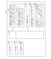
- Step (hereinafter referred to as “ST”) 1 in FIG. 11 the anesthesiologist uses the “server-side display device 303” of “hospital management server 200” in FIG.
- “medicine name (for example, propofol etc.)” and its “execution model” to be attached to the upper mounting portion 201 a, the middle mounting portion 201 b, the lower mounting portion 201 c, etc.
- Information for example, Marsh model
- “Execution model information (for example, Marsh model)” stored in the “rack-mounted medicine information storage unit 307” is an example of second corresponding administration execution process information.
- the drug “propofol”, the execution model “Marsh model”, and the middle mounting unit 201b are stored in the upper mounting unit 201a of the rack device 200 of “rack number 001” in the “rack mounting drug information storage unit 307” of FIG.
- the drug “fentanyl”, the execution model “shafer model”, and the lower mounting portion 201c store the drug “rocuronium” and the execution model “rocuronium administration model”. Therefore, the medicine in the “rack-mounted medicine information storage unit 307” is an example of the second medicine type information.
- a nurse or doctor who is a medical worker prepares to administer an anesthetic to the patient P.
- the nurse attaches the syringe pump 100a and the like of FIGS. 3 and 4 to the upper mounting portion 201a and the like of the rack device 200.
- “patient information” is stored in each syringe pump 100a, 100b, 100c, and specifically, is stored as “patient information” in the “syringe pump side basic information storage unit 121” in FIG. .
- the nurse attaches the syringe pumps 100a, 100b, and 100c to the rack device 200 of FIGS.
- the “syringe pump 100b in which fentanyl is inserted” is inserted in the middle mounting portion 201b
- “rocuronium” is inserted in the lower mounting portion 201c. It is a procedure for mounting the syringe pump 100c.
- the occurrence of such a difference is prevented in the following steps.
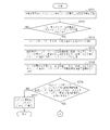
- the “pump attachment portion determination unit (program) 221” of FIG. 8 is operated, and whether or not the syringe pump 100a or the like is connected to any one of the upper attachment portion 201a, the middle attachment portion 201b, and the lower attachment portion 201c. Determine whether. Specifically, the rack connection terminal 101 such as the syringe pump 100a in FIG. 4 is connected to any one of the upper mounting portion terminal 203a, the middle mounting portion terminal 203b, and the lower mounting portion terminal 203c in FIGS. It is determined whether or not it is attached.
- the process proceeds to ST13.
- the process proceeds to ST14.
- the “rack side medicine specifying unit (program) 222” of the rack device 200 of FIG. 8 operates, and the rack number of the rack device of the “rack mounted medicine information storage unit 307” of FIG.
- Information on “medicine (for example, propofol)” and “execution model (for example, Marsh model)” of “upper mounting portion 201a” (for example, rack number 001) is acquired and transmitted to the syringe pump 100a and the like.
- the syringe pump 100a and the like receive the information on “medicine (for example, propofir)” and “execution model (for example, Marsh model)” such as “upper mounting portion 201a” received from the rack apparatus 200 in FIG. It memorize
- the process proceeds to ST16.
- ST16 the “corresponding drug etc. determination unit (program) 123” of FIG. 5 of the syringe pump 100a is operated, and the “syringe pump side acquired drug information storage unit 122” and the “syringe pump side basic information storage unit 121” are referred to.
- the “syringe pump side basic information storage unit 121” includes “medicine (for example, propofol)” that can be administered by the syringe pump 100a and the like and executable “execution model (Marsh model)”.
- the medicine in the “syringe pump side basic information storage unit 121” is an example of the first medicine type information.
- it is determined whether the “medicine” and “execution model” information of the “syringe pump side acquired medicine information storage unit 122” is present in the “syringe pump side basic information storage unit 121”.
- each syringe pump 100a or the like stores a plurality of execution models corresponding to the medicines in advance and can execute any execution model.
- the presence of a syringe pump 100a or the like that does not store a part of it is also conceivable. Therefore, in the present embodiment, it is possible to prevent the malfunction of the syringe pump 100a and the like having such a defect and to prevent the occurrence of an anesthetic administration error and the like.
- ST18 flags are set for “selected drug” of the corresponding drug in “syringe pump side basic information storage unit 121” in FIG. 5 and “execution selection” of “execution model”. For example, when the drug “propofol” and the execution model “Marsh model” of the “syringe pump side acquired drug information storage unit 122” exist, the drug “propofol” is set as “selected drug”, and the execution model “Marsh model” is set as Register as “execution selection”.
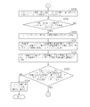
- the “pump attachment portion determination unit (program) 221” of FIG. 8 operates to determine whether the syringe pump 100a or the like is attached to either the middle attachment portion 201b or the lower attachment portion 201c, and ST20 If it is determined that it is attached to the “middle attachment part 201b”, the process proceeds to ST21.
- the “rack side drug identification unit (program) 222” of the rack 200 of FIG. 8 operates, and the rack number of the rack device 200 of the “rack mounted medicine information storage unit 307” of FIG.
- Information on “medicine (for example, fentanyl)” and “execution model (for example, Shaffer model)” of “middle mounting part 201b” (for example, rack number 001) is acquired and transmitted to the syringe pump 100b and the like.
- the syringe pump 100b or the like receives the information of “medicine (for example, fentanyl)” and “execution model (for example, Shaffer model)” such as “middle stage mounting portion 201b” received from the rack apparatus 200 in FIG. It memorize
- the process proceeds to ST23.
- ST23 the “corresponding drug etc. determination unit (program) 123” of FIG. 5 of the syringe pump 100b is operated, and the “syringe pump side acquired drug information storage unit 122” and the “syringe pump side basic information storage unit 121” are referred to.
- the “syringe pump side basic information storage unit 121” includes “medicine (for example, fentanyl)” that can be administered by the syringe pump 100b and the like, and executable “execution model (Shafer model)”. Stored in advance.
- ST23 it is determined whether or not the “medicine” and “execution model” information of the “syringe pump side acquired medicine information storage unit 122” exists in the “syringe pump side basic information storage unit 121”.
- the process proceeds to ST24.
- a warning that “execution selection” of the medicine (anesthetic) cannot be performed is displayed on the “syringe pump side display unit 105” in FIG.
- a message such as “Cannot proceed to next step” or “No drug can be selected for execution” is displayed, and then “Do you want to cancel?” Is displayed. Therefore, similarly to the upper mounting portion 201a, the middle mounting portion 201b can prevent the occurrence of malfunction of the syringe pump 100b and the like, and can prevent the occurrence of an error in anesthetic administration. ing.
- ST25 flags are set for “selected drug” of the corresponding drug in “syringe pump side basic information storage unit 121” in FIG. 5 and “execution selection” of “execution model”. For example, when the drug “fentanyl” and the execution model “Shafer model” in the “syringe pump-side acquired drug information storage unit 122” exist, the drug “fentanyl” is set as “selected drug”, and the execution model “Shafer model” is set. Register as “execution selection”.
- “medicine” and “execution model” of “syringe pump 100b etc.” attached to the middle attachment portion 201b are, for example, “fentanyl” and “Shafer model”.
- the “pump attachment part determination unit (program) 221” of FIG. 8 operates to determine whether or not the syringe pump 100c or the like is attached to the lower attachment part 201c. move on.
- the “rack side medicine specifying unit (program) 222” of the rack 200 of FIG. 8 operates, and the rack number of the rack device 200 of the “rack mounted medicine information storage unit 307” of FIG.
- Information on “drug (eg, rocuronium)” and “execution model (eg, rocuronium administration model)” of “lower mounting portion 201c” is acquired and transmitted to syringe pump 100c and the like.
- the syringe pump 100c and the like receive the information of “drug (for example, rocuronium)” and “execution model (for example, rocuronium administration model)” such as “lower stage mounting portion 201c” received from the rack device 200 in FIG. “Syringe pump side acquired medicine information etc. storage unit 122” is stored.
- drug for example, rocuronium
- execution model for example, rocuronium administration model
- the process proceeds to ST29.
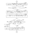
- ST29 the “corresponding drug etc. determination unit (program) 123” of FIG. 5 of the syringe pump 100c operates, and the “syringe pump side acquired drug information storage unit 122” and the “syringe pump side basic information storage unit 121” are referred to.
- the “syringe pump side basic information storage unit 121” includes a “medicine (for example, rocuronium)” that can be administered by the syringe pump 100c and the like, and an executable “execution model (rocuronium administration model)”. Is stored in advance.
- it is determined whether or not the “medicine” and “execution model” information of the “syringe pump side acquired medicine information storage unit 122” exists in the “syringe pump side basic information storage unit 121”.
- ST30 a warning that “execution selection” of the medicine (anesthetic) cannot be performed is displayed on the “syringe pump side display unit 105” in FIG. For example, a message such as “Cannot proceed to next step” or “No drug can be selected for execution” is displayed, and then “Do you want to cancel?” Is displayed. Therefore, similarly to the upper mounting portion 201a, the lower mounting portion 201c can prevent the malfunction of the syringe pump 100c and the like, and can prevent the occurrence of an anesthetic administration error and the like. ing.
- ST31 flags are set for “selected drug” of the corresponding drug in “syringe pump side basic information storage unit 121” in FIG. 5 and “execution selection” of “execution model”. For example, when the drug “rocuronium” in the “syringe pump side acquired drug information storage unit 122” and the execution model “rocuronium execution model” exist, the drug “rocuronium” is set as the “selected drug”, and the execution model “rocuronium execution model” Is registered as “execution selection”.
- “drug” and “execution model” of “syringe pump 100c etc.” attached to the lower attachment part 201c are, for example, “rocuronium” and “rocuronium execution model”. .
- the rack apparatus 200 acquires “patient information” from the “syringe pump side basic information storage unit 121” of FIG. 5 such as the syringe pump 100a of the upper mounting unit 201a, the middle mounting unit 201b, and the lower mounting unit 201c, The data is stored in the “rack side patient information storage unit 223” in FIG.
- the “patient biological information acquisition unit (program) 224” of FIG. 8 of the rack apparatus 200 operates, accesses the “electronic medical record 305” of the “hospital management server 300”, and displays “rack side patient information” of FIG. Based on the “patient information” (for example, patient number) of the storage unit 223, biometric information such as “sex, age, weight, height” of the patient is acquired, and the “rack-side patient biometric information storage unit” of FIG. 225 ".
- ST34 the “model execution data providing unit (program) 226” in FIG. 8 of the rack apparatus 200 operates, and “gender, age, weight, height of the patient in the“ rack-side patient biometric information storage unit 225 ”in FIG. And the like is transmitted to each stage of the syringe pump 100a and the like.
- the “patient biological information” received from the rack apparatus 200 is stored in the “syringe pump side patient biological information storage unit 131” such as the syringe pump 100a of FIG.
- a nurse or the like attaches the syringe 108 containing the specified medicine to all of the syringe pumps 100a and the like attached to the rack device 200.
- the process proceeds to ST36.
- the “syringe attachment confirmation unit (program) 132” of FIG. 6 such as the syringe pump 100a operates to confirm whether or not the syringe 108 is attached to the syringe pump 100a or the like.
- Step37 “drug name” and “execution model name” are displayed on the syringe pump side display unit 105.
- ST38 the “confirmation input determination unit (program) 133” in FIG. 6 operates to determine whether or not there is a “confirmation” input from the operation panel unit 106 such as the syringe pump 100a.
- the syringe pump 100a or the like not only stores the drug and the execution model data administered by the syringe pump 100a or the like, but also displays it and allows the nurse or the like to confirm it.
- the structure prevents the occurrence of mistakes.
- the process proceeds to ST39.
- the “model execution unit (program) 134” of FIG. 6 such as the syringe pump 100a operates, and the “syringe pump side patient biological information storage unit 131” of FIG. 6, the “model execution program storage unit 124” of FIG.
- the model execution program in which the flag is set is executed using the patient's biological information. Specifically, for example, a simulation of the dosage of the drug is derived from the calculation model of the Marsh model and the biological information of the patient stored in the model execution program storage unit 124.
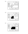
- FIG. 19 is a graph showing a state in which a medicine is being delivered based on such simulation.
- FIG. 19A shows a state immediately after the start of liquid feeding
- FIG. 19B shows a state in which the specific effect site concentration d1 has reached the target
- FIG. 19C shows that the specific effect site concentration d1 has reached the target. The state after reaching the concentration is shown.
- the prediction line of the blood concentration d0 of the drug and the prediction line of the effect site concentration d1 calculated based on the simulation based on the specific model can be displayed on the syringe pump side display unit 105, and the simulation is performed. The effect along can be demonstrated.
- data for limiting the “execution model” to be executed is transmitted from the hospital management server 300 to each syringe pump 100a and the like via the rack device 200. For this reason, each syringe pump 100a etc. can administer a medicine to patient P correctly, without making a mistake. In particular, when an administration error or the like causes a serious result such as an anesthetic, the present embodiment can surely prevent such a result from occurring.
- the rack apparatus 200 acquires the patient biological information from the hospital management server 300 and provides it to the syringe pump 100a or the like without the patient's biological information being input, and the syringe pump 100a or the like is the execution model. Calculate the simulation. Therefore, the labor of a nurse or the like can be reduced, and an input error of biometric information can be prevented in advance.
- the hospital management server 300 determines whether or not a change request has been input.
- the server side display device 303 displays an input screen for “staff ID number” and “password”. Is displayed.
- the input "staff ID number” and “password” are stored in the "input staff information storage unit 308" in FIG. 9 in ST54.
- the process proceeds to ST55.
- the “staff information confirmation unit (program) 309” of FIG. 9 operates to refer to the “input staff information storage unit 308” of FIG. 9 and the “staff database 306” of FIG. 9 of the “hospital management server 300”. Then, the suitability of the “staff ID number” and “password” is determined. If it is determined in ST56 that it is correct, the process proceeds to ST57. In ST57, it is determined whether the affiliation of the “staff ID number” corresponds to an affiliation having the authority to change “medicine” such as “anesthesiologist” or “execution model”, and it is determined in ST58 that it corresponds. If so, proceed to ST59.
- the “medicine” and “execution model” change screens of the upper mounting portion 201a, the middle mounting portion 201b, and the lower mounting portion 201c are displayed on the server side display device 303.
- the process proceeds to ST60, and when the change process is finished, this process is finished.
- the present invention is not limited to the above-described embodiment.
- all the liquid feed pump mounting portions of the upper mounting portion 201a, the middle mounting portion 201b, and the lower mounting portion 201c of the rack device 200 are used.
- the present invention includes all the liquid pump mounting portions. It is not limited to using.
- information on medicines and execution models that can be used by the syringe pump 100a and the like mounted on the upper mounting portion 201a, the middle mounting portion 201b, and the lower mounting portion 201c of the rack device 200 is stored in the “hospital management server 300”.
- the rack apparatus 200 may manage the information.
- SYMBOLS 1 Medical pump system, 100a, 100b, 100c ... Syringe pump, 101 ... Rack connection terminal, 102 ... Syringe pusher, 103 ... Tube, 104 ... Indwelling needle, 105 ... Syringe pump side display unit, 106 ... Operation panel unit, 106a ... Power ON / OFF button, 106b ... Operation indicator, 106c ... Fast forward switch button, 106d ... Start switch button 106e ... Stop switch button, 106f ... Menu selection button, 108 ... Syringe, 110 ... Syringe pump control unit, 120 ...
- First syringe pump side various information storage unit 121 ... ⁇ Syringe pump side basic information storage unit, 122... Syringe pump side acquired drug information storage unit, 123... Equal determination unit (program), 124 ... model execution program storage unit, 130 ... second syringe pump side various information storage unit, 131 ... syringe pump side patient biological information storage unit, 132 ... syringe Mounting confirmation unit (program), 133... Confirmation input determination unit (program), 134... Model execution unit (program), 200... Rack device, 201 a. Mounting part, 201c ... Lower mounting part, 202 ... Communication box, 203 ... Rack side communication device, 203a ... Upper mounting part terminal, 203b ...
Landscapes
- Health & Medical Sciences (AREA)
- Vascular Medicine (AREA)
- Engineering & Computer Science (AREA)
- Anesthesiology (AREA)
- Biomedical Technology (AREA)
- Heart & Thoracic Surgery (AREA)
- Hematology (AREA)
- Life Sciences & Earth Sciences (AREA)
- Animal Behavior & Ethology (AREA)
- General Health & Medical Sciences (AREA)
- Public Health (AREA)
- Veterinary Medicine (AREA)
- Infusion, Injection, And Reservoir Apparatuses (AREA)
Abstract
【課題】ラック装置に装着されている各シリンジポンプ等の送液ポンプについて、それぞれ正しい投与方法を確実に実行することができる送液ポンプ管理システムを提供すること。 【解決手段】送液ポンプ100aと、送液ポンプ装着部201aを複数有する送液ポンプ用ラック装置200と、管理装置300と、を備え、送液ポンプは、第1薬剤種情報121に対応する対応投与実行工程情報121とを記憶し、送液ポンプ用ラック装置又は管理装置は、各送液ポンプ装着部に対応させた第2薬剤種情報307を有し、送液ポンプ装着部の送液ポンプの第1薬剤情報と、対応する第2薬剤種情報とを比較し、第2薬剤種情報と一致しない第1薬剤種情報に対応する対応投与実行情報に従い薬剤の投与を実行することを制限する送液ポンプ管理システム1。
Description
本発明は、送液ポンプである例えば、シリンジポンプ等を複数使用して患者に薬剤を投与する場合に用いられる送液ポンプ管理システムに関するものである。
従来から患者に複数種類の薬剤を投与する場合は、複数の輸液ポンプ(シリンジポンプ)を配置することができるラック装置を使用している(例えば、特許文献1)。
しかしながら、ラック装置に装着されている各シリンジポンプ等に配置されている薬剤の種類が相違し、それぞれの薬剤の投与方法が異なる場合がある。
このような場合、同時にラック装置に配置されている各シリンジポンプ内の薬剤を当該薬剤で定められている投与方法で患者に投与せねばならず、誤って、異なる投与方法を行うと薬剤によっては重篤な事態を招来するおそれがある。
このような場合、同時にラック装置に配置されている各シリンジポンプ内の薬剤を当該薬剤で定められている投与方法で患者に投与せねばならず、誤って、異なる投与方法を行うと薬剤によっては重篤な事態を招来するおそれがある。
そこで、本発明は、ラック装置に装着されている各シリンジポンプ等の送液ポンプについて、それぞれ正しい投与方法を確実に実行することができる送液ポンプ管理システムを提供することを目的とする。
上記目的は、本発明にあっては、薬剤を対象者に投与する送液ポンプと、前記送液ポンプを配置可能な送液ポンプ装着部を複数有する送液ポンプ用ラック装置と、前記送液ポンプ用ラック装置と通信可能に接続されている管理装置と、を備える送液ポンプ管理システムであって、前記送液ポンプは、薬剤の種類情報である第1薬剤種情報と該第1薬剤情報に対応する少なくとも1つの投与方法に関する情報である対応投与実行工程情報とを記憶する記憶部を有し、前記送液ポンプ用ラック装置又は前記管理装置は、各前記送液ポンプ装着部に対応させた薬剤の種類情報である第2薬剤種情報を有し、前記送液ポンプ装着部に装着される送液ポンプの前記第1薬剤情報と、該送液ポンプが装着される前記送液ポンプ装着部に対応する前記第2薬剤種情報とを比較し、前記第2薬剤種情報と一致しない前記第1薬剤種情報に対応する前記対応投与実行情報に従い前記薬剤の投与を実行することを、制限することを特徴とする送液ポンプ管理システムにより達成される。
前記構成によれば、送液ポンプ装着部に装着される送液ポンプの第1薬剤情報(例えば、シリンジポンプ側基本情報記憶部の薬剤名等)と、送液ポンプが装着される送液ポンプ装着部に対応する第2薬剤種情報(例えば、病院管理サーバのラック装着薬剤情報記憶部の薬剤情報)とを比較し、第2薬剤種情報と一致しない第1薬剤種情報に対応する対応投与実行情報(例えば、Marshモデル等の実行モデル)に従い投与を実行することを制限する構成となっている。
このため、誤って、看護師等の医療従事者が、当該送液ポンプ配置部に配置すべき送液ポンプを誤って配置しても、その投与の実行が制限されるので、看護師等に報知されるので、薬剤の投与方法を誤ることがない。
また、送液ポンプは、薬剤の種類情報である第1薬剤種情報に対応する少なくとも1つの投与方法に関する情報である第1対応投与実行工程情報(例えば、Marshモデル等)を記憶するので、薬剤の投与は自動的、かつ間違いなく実行される。
このため、誤って、看護師等の医療従事者が、当該送液ポンプ配置部に配置すべき送液ポンプを誤って配置しても、その投与の実行が制限されるので、看護師等に報知されるので、薬剤の投与方法を誤ることがない。
また、送液ポンプは、薬剤の種類情報である第1薬剤種情報に対応する少なくとも1つの投与方法に関する情報である第1対応投与実行工程情報(例えば、Marshモデル等)を記憶するので、薬剤の投与は自動的、かつ間違いなく実行される。
好ましくは、前記送液ポンプが有する前記対応投与実行工程情報が第1対応投与実行工程情報であり、前記送液ポンプ用ラック装置又は前記管理装置は、各前記送液ポンプ装着部に対応させた投与方法に関する情報である第2対応投与実行工程情報を有し、前記送液ポンプ装着部に装着される送液ポンプの前記第1対応投与実行工程情報と、該送液ポンプが装着される前記送液ポンプ装着部に対応する前記第2対応投与実行工程情報とを比較し、前記第2対応投与実行工程情報と一致しない前記第1対応投与実行情報に従い前記薬剤の投与を実行することを、制限することを特徴とする。
前記構成によれば、送液ポンプ装着部に配置された送液ポンプの第1対応投与実行工程情報が、第2対応投与実行工程情報(例えば、Marshモデル等)に一致しないときは制限されるので、薬剤の投与は自動的、かつ間違いなく実行される。
好ましくは、前記第1薬剤種情報が、前記第2薬剤種情報と一致しないと判断したときは、その旨を出力する構成となっていることを特徴とする。
前記構成によれば、前記第1薬剤種情報が、前記第2薬剤種情報と一致しないと判断したときは、その旨を出力するため、誤って、看護師等の医療従事者が、当該送液ポンプ配置部に配置すべき送液ポンプを誤って配置しても、直ちに、その旨が看護師等に報知されるので、薬剤の投与方法を誤ることがない。
したがって、ラック装置に装着されている各送液ポンプについて、それぞれ正しい投与方法を確実に実行することができる。
したがって、ラック装置に装着されている各送液ポンプについて、それぞれ正しい投与方法を確実に実行することができる。
好ましくは、前記対応投与実行工程の実行に必要な当該対象者の生体情報を前記送液ポンプに提供する構成となっていることを特徴とする。
前記構成によれば、対応投与実行工程の実行に必要な当該対象者の生体情報を送液ポンプに提供する構成となっているので、送液ポンプでかかる生体情報をその都度、看護師等が入力する必要がなく、労力等を省くことができると共に、誤入力等の発生も未然に防止することができる。
前記薬剤が、麻酔薬関連薬剤であることを特徴とする。
前記構成によれば、薬剤が、麻酔薬関連薬剤である。麻酔薬は、種類毎の投与方法を誤ると、極めて重篤な事態の発生となるので、本発明では、かかる重篤な危険の発生を確実に防止することができる。
上記目的は、本発明にあっては、薬剤を対象者に投与する送液ポンプと、前記送液ポンプを配置可能な送液ポンプ装着部を複数有する送液ポンプ用ラック装置と、前記送液ポンプ用ラック装置と通信可能に接続されている管理装置と、を備える送液ポンプ管理システムであって、前記送液ポンプは、投与方法に関する情報である第1対応投与実行工程情報を記憶する記憶部を有し、前記送液ポンプ用ラック装置又は前記管理装置は、各前記送液ポンプ装着部に対応させた投与方法に関する情報である第2対応投与実行工程情報を有し、前記送液ポンプ装着部に装着される送液ポンプの前記第1対応投与実行工程情報と、該送液ポンプが装着される前記送液ポンプ装着部に対応する前記第2対応投与実行工程情報とを比較し、前記第2対応投与実行工程情報と一致しない前記第1対応投与実行情報に従い前記薬剤の投与を実行することを、制限することを特徴とする送液ポンプ管理システムにより達成される。
以上説明したように、本発明によれば、ラック装置に装着されている各シリンジポンプ等の送液ポンプについて、それぞれ正しい投与方法を確実に実行することができる送液ポンプ管理システムを提供することができる。
以下、この発明の好適な実施の形態を、添付図面等を参照しながら、詳細に説明する。
尚、以下に述べる実施の形態は、本発明の好適な具体例であるから、技術的に好ましい種々の限定が付されているが、本発明の範囲は、以下の説明において特に本発明を限定する旨の記載がない限り、これらの態様に限られるものではない。
尚、以下に述べる実施の形態は、本発明の好適な具体例であるから、技術的に好ましい種々の限定が付されているが、本発明の範囲は、以下の説明において特に本発明を限定する旨の記載がない限り、これらの態様に限られるものではない。
図1は、本発明の実施の形態にかかる送液ポンプ管理システムである例えば、医療用ポンプシステム1を示す概略図である。
図1に示すように、医療用ポンプシステム1は、複数、例えば、3台の送液ポンプである例えば、シリンジポンプ100a、シリンジポンプ100b及びシリンジポンプ100cを有している。
このシリンジポンプ100a等は、送液ポンプ用ラック装置である例えば、ラック装置200に装着される構成となっている。
図1に示すように、医療用ポンプシステム1は、複数、例えば、3台の送液ポンプである例えば、シリンジポンプ100a、シリンジポンプ100b及びシリンジポンプ100cを有している。
このシリンジポンプ100a等は、送液ポンプ用ラック装置である例えば、ラック装置200に装着される構成となっている。
図2は、図1のラック装置200の主な構成を示す概略斜視図である。
図1及び図2に示すように、ラック装置200は、シリンジポンプ100a、100b100cをそれぞれ装着可能な送液ポンプ装着部である例えば、上段装着部201a、中段装着部201b、下段装着部201cを有している。
図1及び図2に示すように、ラック装置200は、シリンジポンプ100a、100b100cをそれぞれ装着可能な送液ポンプ装着部である例えば、上段装着部201a、中段装着部201b、下段装着部201cを有している。
また、図2に示すように、上段装着部201a、中段装着部201b、下段装着部201cには、それぞれ、上部装着部用端子203a、中部装着部用端子203b、下部装着部用端子203cが配置され、これらが図1に示すように装着されるシリンジポンプ100a、100b、100cと接続されることで、相互に通信が可能な状態となるように構成されている。
具体的には、後述するシリンジポンプ100a等に配置されているラック接続用端子101と上部装着部用端子203a等が接続されることで、赤外線通信等で、相互に通信可能な構成となっている。
具体的には、後述するシリンジポンプ100a等に配置されているラック接続用端子101と上部装着部用端子203a等が接続されることで、赤外線通信等で、相互に通信可能な構成となっている。
また、図1及び図2に示すように、ラック装置200は、通信ボックス202を有し、病院内に配置される管理装置である例えば、病院管理サーバ300と通信可能に接続されている。
図3は、図1に示すシリンジポンプ100a等の主な構成を示す概略図である。シリンジポンプ100b及び100cは、シリンジポンプ100aと同様の構成であるため説明を省略する。
図3に示すように、シリンジポンプ100aは、薬剤である例えば、薬液を充填したシリンジ108を有し、シリンジ押子102が図3の矢印T方向に移動することでシリンジ108内の薬液を押圧して、チューブ103と留置針104を介して、対象者である例えば、患者に正確に送液する構成となっている。
図3に示すように、シリンジポンプ100aは、薬剤である例えば、薬液を充填したシリンジ108を有し、シリンジ押子102が図3の矢印T方向に移動することでシリンジ108内の薬液を押圧して、チューブ103と留置針104を介して、対象者である例えば、患者に正確に送液する構成となっている。
また、図3に示すように、シリンジポンプ100aは、シリンジポンプ側表示部105を有すると共に、図面における右側に操作パネル部106を有している。
操作パネル部106には、電源ON/OFFボタン106a、動作インジケータ106b、早送りスイッチボタン106c、開始スイッチボタン106d、停止スイッチボタン106e、及びメニュー選択ボタン106f等が配置されている。
操作パネル部106には、電源ON/OFFボタン106a、動作インジケータ106b、早送りスイッチボタン106c、開始スイッチボタン106d、停止スイッチボタン106e、及びメニュー選択ボタン106f等が配置されている。
図1に示すラック装置200、シリンジポンプ100a等及び病院管理サーバ300等は、コンピュータを有し、コンピュータは、図示しないCPU(Central Processing Unit)、RAM(Random Access Memory)、ROM(Read Only Memory)等を有し、これらは、バスを介して接続されている。
図4は、図1及び図3のシリンジポンプ100aの主な構成を示す概略ブロック図である。
図4に示すように、シリンジポンプ100aは「シリンジポンプ制御部10」を有し、シリンジポンプ制御部110は、シリンジポンプ全体の判断・制御を行うもので、上述のシリンジポンプ側表示部105、操作パネル部106及びラック接続用端子101等を制御する他、「第1のシリンジポンプ側各種情報記憶部120」及び「第2のシリンジポンプ側各種情報記憶部130」も制御する構成となっている。
図5は、図4の第1のシリンジポンプ側各種情報記憶部120の主な構成を示す概略ブロック図であり、図6は図4の第2のシリンジポンプ側各種情報記憶部130の主な構成を示す概略ブロック図である。図5及び図6の各ブロックの内容については、後述する。
図7は、図1及び図2に示すラック装置200の主な構成を示す概略ブロック図である。図7に示すように、ラック装置200は「ラック制御部210」を有し、ラック制御部210は、通信ボックス202に配置されている、図1の病院管理サーバ300及びシリンジポンプ100a等と通信するための「ラック側通信装置204」、各種情報を表示する「ラック側表示部205」及び各種情報を入力するキーボード等「ラック側各種情報入力部206」等を制御している。
また、ラック制御部210は上述の上部装着用端子203a、中部装着用端子203b、下部装着用端子203c等も制御する。さらに、ラック制御部210は、図6の「ラック側各種情報記憶部220」も制御する。
図8は、ラック側各種情報記憶部220の主な構成を示す概略ブロック図である。これらの内容の説明は後述する。
図9は病院管理サーバ300の主な構成を示す概略ブロック図である。
図9に示すように、病院管理サーバ300は、「サーバ制御部301」を有し、サーバ制御部301は、図1のラック装置200等と通信するための「サーバ側通信装置302」、各種情報を表示するための「サーバ側表示装置303」及び各種情報を入力するキーボード等の「サーバ側各種情報入力装置304」等を制御する他、図10に示す「電子カルテデータベース305」や「職員データベース306」も制御する。
また、サーバ制御部301は、「ラック装着薬剤記憶部307」、「入力職員情報記憶部308」及び「職員情報確認部(プログラム)309」も制御するが、これらの内容については後述する。
図10は、図9のラック装着薬剤記憶部307の主な構成を示す概略図である。
図11乃至図18は、本実施の形態にかかる医療用ポンプシステム1の主な動作例等を示す概略フローチャートである。
以下、フローチャートに沿って、各動作等を説明すると共に、図1乃至図10等の構成も併せて説明する。
以下、フローチャートに沿って、各動作等を説明すると共に、図1乃至図10等の構成も併せて説明する。
本実施の形態の薬剤(薬液)は、例えば、麻酔薬であり、薬液としては麻酔薬関連薬液である例えば、「鎮静薬」、「鎮痛薬」及び「筋弛緩薬」をそれぞれ、異なるシリンジポンプ100a等から患者に静脈を介して投与する。
このとき、鎮静薬や鎮痛薬の投与量は厳格に定められており、この量を間違うと危険なため、慎重に管理される。
このとき、鎮静薬や鎮痛薬の投与量は厳格に定められており、この量を間違うと危険なため、慎重に管理される。
従来は、これらの薬剤の投与量の調整は、薬剤の血中濃度をリアルタイムでモニターし、その結果に基づいて投与量を調節しつつ、一定の薬物血液濃度を維持し、それにより一定の薬効を期待していた。
しかし、実際の臨床で薬物濃度をリアルタイムでモニターすることは困難であるため「TCI(taget controlled infusion)」「目標制御注入法」が近年、用いられている。
しかし、実際の臨床で薬物濃度をリアルタイムでモニターすることは困難であるため「TCI(taget controlled infusion)」「目標制御注入法」が近年、用いられている。
このTCIは、薬物動態モデルを用いてシリンジポンプ100a等の投与速度を調節し、望んだ値に薬物をコントロールする方法である。すなわち、TCIでは、薬物動態をコンピュータを用いてシミュレーションし、予測血中濃度を算出し、その結果に基づいて薬物投与量を調節する方法である。
このシミュレーションは、例えば、薬物動態学に基づいて3ーコンパートメントモデルを用いて行われる。
3-コンパートモデルを用いたシミュレーションは、体内を3つの部分(以下、「コンパートメント」という。)に分けて濃度の計算を行う。3つのコンパートメントの1つは、血液をモデル化したコンパートメントである。
また、他の2つのコンパートメントは、生体内における筋肉などの血流が豊富な組織と脂肪などの血流が粗な組織をそれぞれモデル化したものである。
3-コンパートモデルを用いたシミュレーションは、体内を3つの部分(以下、「コンパートメント」という。)に分けて濃度の計算を行う。3つのコンパートメントの1つは、血液をモデル化したコンパートメントである。
また、他の2つのコンパートメントは、生体内における筋肉などの血流が豊富な組織と脂肪などの血流が粗な組織をそれぞれモデル化したものである。
薬剤は、血液をモデル化したコンパートメントに投与される。そして、血液をモデル化したコンパートメントと、他の2つのコンパートメントとの間で、薬剤が所定の移行速度で移動する。
また、薬剤は、血液をモデル化したコンパートメントを介して所定の排泄速度で体外に排泄される。
したがって、薬剤が送液される患者の情報(性別、年齢、身長、体重等)と、送液された薬剤の量、コンパートメントへの移行速度、及び、排泄速度等の関係から、血中濃度を含む各コンパートメントにおける送液された薬剤の濃度を計算することができる。
また、薬剤は、血液をモデル化したコンパートメントを介して所定の排泄速度で体外に排泄される。
したがって、薬剤が送液される患者の情報(性別、年齢、身長、体重等)と、送液された薬剤の量、コンパートメントへの移行速度、及び、排泄速度等の関係から、血中濃度を含む各コンパートメントにおける送液された薬剤の濃度を計算することができる。
このように、コンパートメントに、薬剤が適用される部位をモデル化したコンパートメントを含めることで、薬剤が適用される部位の濃度である効果部位濃度を演算することができる。
例えば、効果部位として鎮静薬(例えば、「プロポフォール」)や鎮痛薬(例えば、「フェンタニル」)の場合は「脳」、筋弛緩薬(例えば、「ロクロニウム」)の場合は、神経筋接合部が考えられる。送液量は、このように計算された薬剤の血中濃度または効果部位濃度と設定された目標濃度との差分に基づいて計算される。
例えば、効果部位として鎮静薬(例えば、「プロポフォール」)や鎮痛薬(例えば、「フェンタニル」)の場合は「脳」、筋弛緩薬(例えば、「ロクロニウム」)の場合は、神経筋接合部が考えられる。送液量は、このように計算された薬剤の血中濃度または効果部位濃度と設定された目標濃度との差分に基づいて計算される。
この3-コンパートメントモデルには、その式等の相違から複数の種類があり、例えば、鎮静薬の「プロポフォール」では「Marshモデル」「Modified Marshモデル」がある。一方、鎮痛薬の「フェンタニル」では、「Shaferモデル」等がある。
本実施の形態では、患者Pに麻酔をかけるとき、鎮静薬として「プロポフォール」、鎮痛薬として「フェンタニル」、そして、筋弛緩薬として「ロクロニウム」を用いる例で以下、説明する。
また、「プロポフォール」は「Marshモデル」で投与され、「フェンタニル」は「Shaferモデル」で投与される例で説明する。
したがって、「Marshモデル」や「Shaferモデル」は、対応投与実行工程情報の一例となっている。
また、「プロポフォール」は「Marshモデル」で投与され、「フェンタニル」は「Shaferモデル」で投与される例で説明する。
したがって、「Marshモデル」や「Shaferモデル」は、対応投与実行工程情報の一例となっている。
これらの「プロポフォール」、「フェンタニル」そして、「ロクロニウム」の各薬剤は、それぞれ別のシリンジポンプ100a等に配置され、患者に投与される。
これら「プロポフォール」、「フェンタニル」そして、「ロクロニウム」の各薬剤が薬剤種情報の一例となっている。
具体的には、図1のラック装置200の上段装着部201aには、「プロポフォール」、中段装着部201bには、「フェンタニル」、そして、下段装着部201cには、「ロクロニウム」が配置されると予め定められている。
これら「プロポフォール」、「フェンタニル」そして、「ロクロニウム」の各薬剤が薬剤種情報の一例となっている。
具体的には、図1のラック装置200の上段装着部201aには、「プロポフォール」、中段装着部201bには、「フェンタニル」、そして、下段装着部201cには、「ロクロニウム」が配置されると予め定められている。
一方、シリンジポンプ100a等には、これら「プロポフォール」、「フェンタニル」又は「ロクロニウム」のいずれかの薬剤が配置される可能性があるため、各シリンジポンプ100a等には、それぞれ、「プロポフォール」を配置したときに適用される複数のモデル「Marshモデル」「Modified Marshモデル」「Schneiderモデル」の計算式等のソフトウエア(プログラム)が格納されていると共に、「フェンタニル」が配置されたときに適用されるモデル「Shaferモデル」の計算式等も記憶されている。
以上のような前提で、以下、具体的に実施形態を説明する。
先ず、図11のStep(以下「ST」とする。)1では、麻酔科医が、図9の「病院管理サーバ200」の「サーバ側表示装置303」等を介して、病院内で使用する図2に示す、各ラック装置200等について、各別に上段装着部201a等、中段装着部201b等、下段装着部201c等に装着すべき「薬剤名(例えば、プロポフォール等)」とその「実行モデル情報(例えば、Marshモデル)」を入力する。
具体的には、図10の「ラック装着薬剤情報記憶部307」に記憶する。
このラック装着薬剤情報記憶部307」に記憶される「実行モデル情報(例えば、Marshモデル)」が、第2対応投与実行工程情報の一例となる。
先ず、図11のStep(以下「ST」とする。)1では、麻酔科医が、図9の「病院管理サーバ200」の「サーバ側表示装置303」等を介して、病院内で使用する図2に示す、各ラック装置200等について、各別に上段装着部201a等、中段装着部201b等、下段装着部201c等に装着すべき「薬剤名(例えば、プロポフォール等)」とその「実行モデル情報(例えば、Marshモデル)」を入力する。
具体的には、図10の「ラック装着薬剤情報記憶部307」に記憶する。
このラック装着薬剤情報記憶部307」に記憶される「実行モデル情報(例えば、Marshモデル)」が、第2対応投与実行工程情報の一例となる。
例えば、図10の「ラック装着薬剤情報記憶部307」の「ラック番号001」のラック装置200の上段装着部201aには、薬剤「プロポフォール」、実行モデル「Marshモデル」、中段装着部201bには、薬剤「フェンタニル」、実行モデル「shaferモデル」、下段装着部201cには薬剤「ロクロニウム」、実行モデル「ロクロニウム投与モデル」と記憶する。
したがって、「ラック装着薬剤情報記憶部307」の薬剤が、第2薬剤種情報の一例となっている。
したがって、「ラック装着薬剤情報記憶部307」の薬剤が、第2薬剤種情報の一例となっている。
以上で、麻酔科医等の権限のある担当者のラック装置200の上段装着部201a等の「薬剤」及び「実行モデル」の入力工程が終了する。
このように、本実施の形態では、各ラック装置200の上段装着部201a、中段装着部201b、下段装着部201cに装着すべき薬剤及び実行モデルが権限ある麻酔科医等の担当者により設定されるので、誤った情報が設定される事態の発生を未然に予防することができる。
このように、本実施の形態では、各ラック装置200の上段装着部201a、中段装着部201b、下段装着部201cに装着すべき薬剤及び実行モデルが権限ある麻酔科医等の担当者により設定されるので、誤った情報が設定される事態の発生を未然に予防することができる。
次いで、医療従事者である例えば、看護師又は医師が患者Pに麻酔薬を投与する準備を行う。
先ず、図12のST11で、看護師が図3及び図4のシリンジポンプ100a等をラック装置200の上段装着部201a等に装着する。
また、各シリンジポンプ100a、100b、100cには、「患者情報」が記憶されており、具体的には、図5の「シリンジポンプ側基本情報記憶部121」の「患者情報」として記憶される。
先ず、図12のST11で、看護師が図3及び図4のシリンジポンプ100a等をラック装置200の上段装着部201a等に装着する。
また、各シリンジポンプ100a、100b、100cには、「患者情報」が記憶されており、具体的には、図5の「シリンジポンプ側基本情報記憶部121」の「患者情報」として記憶される。
次いで、ST12で、看護師は、シリンジポンプ100a、100b、100cを図1及び図2のラック装置200に装着する。このとき、上段装着部201aに「プロポフォール」が挿入されているシリンジポンプ100a、中段装着部201bに「フェンタニルが挿入されているシリンジポンプ100b、そして、下段装着部201cに「ロクロニウム」が挿入されているシリンジポンプ100cを装着する手順となっている。
しかし、相違が生じる可能性もあるので、本実施の形態では、以下の工程でかかる相違の発生を未然に防止する。
しかし、相違が生じる可能性もあるので、本実施の形態では、以下の工程でかかる相違の発生を未然に防止する。
先ず、ST12では、図8の「ポンプ装着部分判断部(プログラム)221」が動作し、上段装着部201a、中段装着部201b又は下段装着部201cのいずれかにシリンジポンプ100a等が接続されたか否かを判断する。
具体的には、図4のシリンジポンプ100a等のラック接続用端子101が、図2及び図7の上部装着部用端子203a、中部装着部用端子203b又は下部装着部用端子203cのいずれかに装着されたか否かを判断する。
具体的には、図4のシリンジポンプ100a等のラック接続用端子101が、図2及び図7の上部装着部用端子203a、中部装着部用端子203b又は下部装着部用端子203cのいずれかに装着されたか否かを判断する。
次いで、ST13へ進み、例えば、シリンジポンプ100a等が上部装着部201aに装着されたと判断すると、ST14へ進む。
ST14では、図8のラック装置200の「ラック側薬剤等特定部(プログラム)222」が動作し、病院管理サーバ300の図10の「ラック装着薬剤情報記憶部307」の当該ラック装置のラック番号(例えば、ラック番号001)の「上段装着部201a」の「薬剤(例えば、プロポフォール)」及び「実行モデル(例えば、Marshモデル)」の情報を取得し、シリンジポンプ100a等に送信する。
ST14では、図8のラック装置200の「ラック側薬剤等特定部(プログラム)222」が動作し、病院管理サーバ300の図10の「ラック装着薬剤情報記憶部307」の当該ラック装置のラック番号(例えば、ラック番号001)の「上段装着部201a」の「薬剤(例えば、プロポフォール)」及び「実行モデル(例えば、Marshモデル)」の情報を取得し、シリンジポンプ100a等に送信する。
次いで、ST15へ進む。ST15では、シリンジポンプ100a等が、ラック装置200から受信した「上段装着部201a」等の「薬剤(例えば、プロポフィール)」及び「実行モデル(例えば、Marshモデル)」の情報を図5の「シリンジポンプ側取得薬剤情報等記憶部122」に記憶する。
次いで、ST16へ進む。ST16では、シリンジポンプ100aの図5の「対応薬剤等判断部(プログラム)123」が動作し、「シリンジポンプ側取得薬剤情報等記憶部122」と「シリンジポンプ側基本情報記憶部121」を参照する。
「シリンジポンプ側基本情報記憶部121」には、当該シリンジポンプ100a等が投与可能な「薬剤(例えば、プロポフォール)」と、実行可能な「実行モデル(Marshモデル)」が図5に示すように予め記憶されている。
したがって、「シリンジポンプ側基本情報記憶部121」の薬剤等は、第1薬剤種情報の一例となっている。
ところで、ST16では、「シリンジポンプ側取得薬剤情報等記憶部122」の「薬剤」及び「実行モデル」情報が「シリンジポンプ側基本情報記憶部121」に存在するか否かを判断する。
「シリンジポンプ側基本情報記憶部121」には、当該シリンジポンプ100a等が投与可能な「薬剤(例えば、プロポフォール)」と、実行可能な「実行モデル(Marshモデル)」が図5に示すように予め記憶されている。
したがって、「シリンジポンプ側基本情報記憶部121」の薬剤等は、第1薬剤種情報の一例となっている。
ところで、ST16では、「シリンジポンプ側取得薬剤情報等記憶部122」の「薬剤」及び「実行モデル」情報が「シリンジポンプ側基本情報記憶部121」に存在するか否かを判断する。
ST16で「存在しない」と判断されたときは、看護師等がシリンジポンプ100a等を間違った段に装着等したと判断し、ST17へ進む。
ST17では、図4の「シリンジポンプ側表示部105」に薬剤(麻酔薬)の「実行選択」できない旨の警告を表示する。例えば、「次のステップへ進めません。」「実行選択できる薬剤がありません。」等の表示を行い、次に「取り消しますか?」等の表示を行う。
したがって、看護師等が誤った薬剤を投与等するのを未然に防止することができる。
また、上述のように原則として、各シリンジポンプ100a等は、薬剤に対応する複数の実行モデルを予め記憶され、どの実行モデルも実行可能な状態となっているが、場合によって、所定の実行モデルの一部を記憶していないシリンジポンプ100a等の存在も考えられる。
そこで、本実施の形態では、かかる欠陥を有するシリンジポンプ100a等の不動作等の発生を未然に防ぎ、麻酔薬の投与の誤り等の発生を未然に防止することができる構成となっている。
一方、ST16で、「存在する」ときは、ST18へ進む。ST18では、図5の「シリンジポンプ側基本情報記憶部121」の対応薬剤の「選択薬剤」と、「実行モデル」の「実行選択」にフラグを立てる。
例えば、「シリンジポンプ側取得薬剤情報等記憶部122」の薬剤「プロポフォール」及び実行モデル「Marshモデル」が存在するときは、薬剤「プロポフォール」を「選択薬剤」とし、実行モデル「Marshモデル」を「実行選択」として登録する。
例えば、「シリンジポンプ側取得薬剤情報等記憶部122」の薬剤「プロポフォール」及び実行モデル「Marshモデル」が存在するときは、薬剤「プロポフォール」を「選択薬剤」とし、実行モデル「Marshモデル」を「実行選択」として登録する。
したがって、これにより、上段装着部201aに装着された「シリンジポンプ100a等」の「薬剤」と「実行モデル」は、例えば、「プロポフォール」と「Marshモデル」であることが明確に記憶される。
次いで、ST19へ進む。ST19では、図8の「ポンプ装着部分判断部(プログラム)221」が動作し、中段装着部201b,または下段装着部201cのいずれかにシリンジポンプ100a等が装着されたか否かを判断し、ST20で「中段装着部201b」に装着されたと判断されると、ST21へ進む。
ST21では、図8のラック200の「ラック側薬剤等特定部(プログラム)222」が動作し、病院管理サーバ300の図10の「ラック装着薬剤情報記憶部307」の当該ラック装置200のラック番号(例えば、ラック番号001)の「中段装着部201b」の「薬剤(例えば、フェンタニル)」及び「実行モデル(例えば、Shaferモデル)」の情報を取得し、シリンジポンプ100b等に送信する。
次いで、ST22へ進む。ST22では、シリンジポンプ100b等が、ラック装置200から受信した「中段段装着部201b」等の「薬剤(例えば、フェンタニル)」及び「実行モデル(例えば、Shaferモデル)」の情報を図5の「シリンジポンプ側取得薬剤情報等記憶部122」に記憶する。
次いで、ST23へ進む。ST23では、シリンジポンプ100bの図5の「対応薬剤等判断部(プログラム)123」が動作し、「シリンジポンプ側取得薬剤情報等記憶部122」と「シリンジポンプ側基本情報記憶部121」を参照する。
「シリンジポンプ側基本情報記憶部121」には、当該シリンジポンプ100b等が投与可能な「薬剤(例えば、フェンタニル)」と、実行可能な「実行モデル(Shaferモデル)」が図5に示すように予め記憶されている。
ところで、ST23では、「シリンジポンプ側取得薬剤情報等記憶部122」の「薬剤」及び「実行モデル」情報が「シリンジポンプ側基本情報記憶部121」に存在するか否かを判断する。
「シリンジポンプ側基本情報記憶部121」には、当該シリンジポンプ100b等が投与可能な「薬剤(例えば、フェンタニル)」と、実行可能な「実行モデル(Shaferモデル)」が図5に示すように予め記憶されている。
ところで、ST23では、「シリンジポンプ側取得薬剤情報等記憶部122」の「薬剤」及び「実行モデル」情報が「シリンジポンプ側基本情報記憶部121」に存在するか否かを判断する。
ST23で「存在しない」と判断されたときは、看護師等がシリンジポンプ100b等を間違った段に装着等したと判断し、ST24へ進む。
ST24では、図4の「シリンジポンプ側表示部105」に薬剤(麻酔薬)の「実行選択」できない旨の警告を表示する。例えば、「次のステップへ進めません。」「実行選択できる薬剤がありません。」等の表示を行い、次に「取り消しますか?」等の表示を行う。
したがって、中段装着部201bでも上段装着部201aと同様に、シリンジポンプ100b等の不動作等の発生を未然に防ぎ、麻酔薬の投与の誤り等の発生を未然に防止することができる構成となっている。
ST24では、図4の「シリンジポンプ側表示部105」に薬剤(麻酔薬)の「実行選択」できない旨の警告を表示する。例えば、「次のステップへ進めません。」「実行選択できる薬剤がありません。」等の表示を行い、次に「取り消しますか?」等の表示を行う。
したがって、中段装着部201bでも上段装着部201aと同様に、シリンジポンプ100b等の不動作等の発生を未然に防ぎ、麻酔薬の投与の誤り等の発生を未然に防止することができる構成となっている。
一方、ST23で、「存在する」ときは、ST25へ進む。ST25では、図5の「シリンジポンプ側基本情報記憶部121」の対応薬剤の「選択薬剤」と、「実行モデル」の「実行選択」にフラグを立てる。
例えば、「シリンジポンプ側取得薬剤情報等記憶部122」の薬剤「フェンタニル」及び実行モデル「Shaferモデル」が存在するときは、薬剤「フェンタニル」を「選択薬剤」とし、実行モデル「Shaferモデル」を「実行選択」として登録する。
例えば、「シリンジポンプ側取得薬剤情報等記憶部122」の薬剤「フェンタニル」及び実行モデル「Shaferモデル」が存在するときは、薬剤「フェンタニル」を「選択薬剤」とし、実行モデル「Shaferモデル」を「実行選択」として登録する。
したがって、これにより、中段装着部201bに装着された「シリンジポンプ100b等」の「薬剤」と「実行モデル」は、例えば、「フェンタニル」と「Shaferモデル」であることが明確に記憶される。
次いで、ST26へ進む。ST26では、図8の「ポンプ装着部分判断部(プログラム)221」が動作し、下段装着部201cにシリンジポンプ100c等が装着されたか否かを判断し、装着されたと判断されると、ST27へ進む。
ST27では、図8のラック200の「ラック側薬剤等特定部(プログラム)222」が動作し、病院管理サーバ300の図10の「ラック装着薬剤情報記憶部307」の当該ラック装置200のラック番号(例えば、ラック番号001)の「下段装着部201c」の「薬剤(例えば、ロクロニウム)」及び「実行モデル(例えば、ロクロニウム投与モデル)」の情報を取得し、シリンジポンプ100c等に送信する。
次いで、ST28へ進む。ST28では、シリンジポンプ100c等が、ラック装置200から受信した「下段段装着部201c」等の「薬剤(例えば、ロクロニウム)」及び「実行モデル(例えば、ロクロニウム投与モデル)」の情報を図5の「シリンジポンプ側取得薬剤情報等記憶部122」記憶する。
次いで、ST29へ進む。ST29では、シリンジポンプ100cの図5の「対応薬剤等判断部(プログラム)123」が動作し、「シリンジポンプ側取得薬剤情報等記憶部122」と「シリンジポンプ側基本情報記憶部121」を参照する。
「シリンジポンプ側基本情報記憶部121」には、当該シリンジポンプ100c等が投与可能な「薬剤(例えば、ロクロニウム)」と、実行可能な「実行モデル(ロクロニウム投与モデル)」が図5に示すように予め記憶されている。
ところで、ST29では、「シリンジポンプ側取得薬剤情報等記憶部122」の「薬剤」及び「実行モデル」情報が「シリンジポンプ側基本情報記憶部121」に存在するか否かを判断する。
「シリンジポンプ側基本情報記憶部121」には、当該シリンジポンプ100c等が投与可能な「薬剤(例えば、ロクロニウム)」と、実行可能な「実行モデル(ロクロニウム投与モデル)」が図5に示すように予め記憶されている。
ところで、ST29では、「シリンジポンプ側取得薬剤情報等記憶部122」の「薬剤」及び「実行モデル」情報が「シリンジポンプ側基本情報記憶部121」に存在するか否かを判断する。
ST29で「存在しない」と判断されたときは、看護師等がシリンジポンプ100c等を間違った段に装着等したと判断し、ST30へ進む。
ST30では、図4の「シリンジポンプ側表示部105」に薬剤(麻酔薬)の「実行選択」できない旨の警告を表示する。例えば、「次のステップへ進めません。」「実行選択できる薬剤がありません。」等の表示を行い、次に「取り消しますか?」等の表示を行う。
したがって、下段装着部201cでも上段装着部201aと同様に、シリンジポンプ100c等の不動作等の発生を未然に防ぎ、麻酔薬の投与の誤り等の発生を未然に防止することができる構成となっている。
ST30では、図4の「シリンジポンプ側表示部105」に薬剤(麻酔薬)の「実行選択」できない旨の警告を表示する。例えば、「次のステップへ進めません。」「実行選択できる薬剤がありません。」等の表示を行い、次に「取り消しますか?」等の表示を行う。
したがって、下段装着部201cでも上段装着部201aと同様に、シリンジポンプ100c等の不動作等の発生を未然に防ぎ、麻酔薬の投与の誤り等の発生を未然に防止することができる構成となっている。
一方、ST29で、「存在する」ときは、ST31へ進む。ST31では、図5の「シリンジポンプ側基本情報記憶部121」の対応薬剤の「選択薬剤」と、「実行モデル」の「実行選択」にフラグを立てる。
例えば、「シリンジポンプ側取得薬剤情報等記憶部122」の薬剤「ロクロニウム」及び実行モデル「ロクロニウム実行モデル」が存在するときは、薬剤「ロクロニウム」を「選択薬剤」とし、実行モデル「ロクロニウム実行モデル」を「実行選択」として登録する。
例えば、「シリンジポンプ側取得薬剤情報等記憶部122」の薬剤「ロクロニウム」及び実行モデル「ロクロニウム実行モデル」が存在するときは、薬剤「ロクロニウム」を「選択薬剤」とし、実行モデル「ロクロニウム実行モデル」を「実行選択」として登録する。
したがって、これにより、下段装着部201cに装着された「シリンジポンプ100c等」の「薬剤」と「実行モデル」は、例えば、「ロクロニウム」と「ロクロニウム実行モデル」であることが明確に記憶される。
ST29で、「存在する」と判断されたときは、ラック装置200に装着されているシリンジポンプ100a等は、全て適切に装着され、実行モデルのデータも有しているので、次いで、各シリンジポンプ100a等が、それぞれに実行モデルを計算するに必要な情報取得処理等を行う。
具体的には、ST32へ進む。ST32では、ラック装置200が上段装着部201a、中段装着部201b及び下段装着部201cのシリンジポンプ100a等の図5の「シリンジポンプ側基本情報記憶部121」から「患者情報」を取得して、図8の「ラック側患者情報記憶部223」に記憶させる。
次いで、ST33へ進む。ST33では、ラック装置200の図8の「患者生体情報取得部(プログラム)224」が動作し、「病院管理サーバ300」の「電子カルテ305」にアクセスして、図8の「ラック側患者情報記憶部223」の「患者情報」(例えば、患者番号)に基づき、当該患者の「性別、年齢、体重、身長」等の生体情報を取得して、図8の「ラック側患者生体情報記憶部225」に記憶する。
次いで、ST34へ進む。ST34では、ラック装置200の図8の「モデル実行データ提供部(プログラム)226」が動作し、図8の「ラック側患者生体情報記憶部225」の当該患者の「性別、年齢、体重、身長」等の生体情報を各段のシリンジポンプ100a等に送信する。
次いで、ST35へ進む。ST35では、ラック装置200から受信した「患者の生体情報」を図6のシリンジポンプ100a等の「シリンジポンプ側患者生体情報記憶部131」に記憶する。
次いで、看護師等が、ラック装置200に装着されているシリンジポンプ100a等の全てに、指定の薬剤を収容しているシリンジ108を装着する。
次いで、ST36に進む。ST36では、シリンジポンプ100a等の図6の「シリンジ装着確認部(プログラム)132」が動作し、シリンジ108がシリンジポンプ100a等に装着されたか否かを確認する。
次いで、ST36に進む。ST36では、シリンジポンプ100a等の図6の「シリンジ装着確認部(プログラム)132」が動作し、シリンジ108がシリンジポンプ100a等に装着されたか否かを確認する。
装着されたことが確認されると、ST37へ進む。ST37では、シリンジポンプ側表示部105に「薬剤名」及び「実行モデル名」が表示される。
次いで、ST38へ進む。ST38では、図6の「確認入力判断部(プログラム)133」が動作して、シリンジポンプ100a等の操作パネル部106から「確認」入力があったか否かを判断する。
次いで、ST38へ進む。ST38では、図6の「確認入力判断部(プログラム)133」が動作して、シリンジポンプ100a等の操作パネル部106から「確認」入力があったか否かを判断する。
したがって、本実施の形態では、シリンジポンプ100a等に、当該シリンジポンプ100a等が投与する薬剤及び実行モデルのデータを記憶させているだけでなく、更に、表示し、看護師等に確認させることで、間違い等の発生を未然に防ぐ構成となっている。
ST38で、確認されると、ST39へ進む。ST39ではシリンジポンプ100a等の図6の「モデル実行部(プログラム)134」が動作し、図6の「シリンジポンプ側患者生体情報記憶部131」、図5の「モデル実行プログラム記憶部124」及び「シリンジポンプ側基本情報記憶部121」の「フラグ」を参照し、患者の生体情報を用いて、フラグが立っている当該モデル実行プログラム、例えば、Marshモデル実行プログラム等を実行する。
具体的には、モデル実行プログラム記憶部124に記憶されている、例えば、Marshモデルの計算式と患者の生体情報等から、薬剤の投与量等のシミュレーションを導くことになる。
具体的には、モデル実行プログラム記憶部124に記憶されている、例えば、Marshモデルの計算式と患者の生体情報等から、薬剤の投与量等のシミュレーションを導くことになる。
図19は、かかるシミュレーションに基づき薬剤が送液されている状態を示すグラフである。
図19(a)は、送液開始直後の状態であり、(b)は、特定の効果部位濃度d1が目標に達した状態を示し、(c)は、特定の効果部位濃度d1が、目標濃度に達した後の状態を示す。
このように、特定のモデルに基づくシミュレーションに基づいて計算される薬剤の血中濃度d0の予測線及び効果部位濃度d1の予測線をシリンジポンプ側表示部105に表示させることができると共に、そのシミュレーションに沿った効果を発揮させることができる。
図19(a)は、送液開始直後の状態であり、(b)は、特定の効果部位濃度d1が目標に達した状態を示し、(c)は、特定の効果部位濃度d1が、目標濃度に達した後の状態を示す。
このように、特定のモデルに基づくシミュレーションに基づいて計算される薬剤の血中濃度d0の予測線及び効果部位濃度d1の予測線をシリンジポンプ側表示部105に表示させることができると共に、そのシミュレーションに沿った効果を発揮させることができる。
このように本実施の形態では、病院管理サーバ300からラック装置200を介して各シリンジポンプ100a等へ実行すべき「実行モデル」を限定するデータを送信する。このため、各シリンジポンプ100a等は、間違えることなく正確に薬剤を患者Pに投与することができる。
特に、麻酔薬等のように、投与間違い等が重篤な結果を招来する場合は、本実施の形態では、かかる結果の発生を確実に防止することができる。
特に、麻酔薬等のように、投与間違い等が重篤な結果を招来する場合は、本実施の形態では、かかる結果の発生を確実に防止することができる。
また、本実施の形態では、患者の生体情報を看護師等が入力することなく、ラック装置200が病院管理サーバ300から取得して、シリンジポンプ100a等へ提供し、シリンジポンプ100a等が実行モデルのシミュレーションの計算をする。したがって、看護師等の労力を軽減させることができると共に、生体情報の入力ミス等を未然に防止することができる。
次いで、図10の病院管理サーバ300の「ラック装着薬剤情報記憶部307」の「薬剤」や「実行モデル」の登録を変更する場合について、図17及び図18のフローチャートを用いて説明する。
先ず、図17のST50では、サーバ側表示装置303が表示する「メニュー」画面から図10の「ラック装着薬剤記憶部307」の「上段装着部」「中段装着部」「下段装着部」「薬剤」と「実行モデル」の変更画面を表示させる。
先ず、図17のST50では、サーバ側表示装置303が表示する「メニュー」画面から図10の「ラック装着薬剤記憶部307」の「上段装着部」「中段装着部」「下段装着部」「薬剤」と「実行モデル」の変更画面を表示させる。
次いで、ST51で、病院管理サーバ300は、変更要求が入力されたか否かを判断し、入力されたときは、ST52で、サーバ側表示装置303が「職員ID番号」及び「パスワード」の入力画面を表示する。
次いで、ST53で、入力されたときは、ST54で、入力された「職員ID番号」及び「パスワード」を図9の「入力職員情報記憶部308」に記憶させる。
次いで、ST53で、入力されたときは、ST54で、入力された「職員ID番号」及び「パスワード」を図9の「入力職員情報記憶部308」に記憶させる。
次いで、ST55へ進む。ST55では、図9の「職員情報確認部(プログラム)309」が動作して、図9の「入力職員情報記憶部308」と「病院管理サーバ300」の図9の「職員データベース306」を参照し、当該「職員ID番号」と「パスワード」の適否を判断する。
ST56で、正しいと判断したときは、ST57へ進む。ST57では、当該「職員ID番号」の所属が「麻酔科医」等の「薬剤」や「実行モデル」を変更する権限を有する所属に該当するか否か判断し、ST58で、該当すると判断したときは、ST59へ進む。
ST56で、正しいと判断したときは、ST57へ進む。ST57では、当該「職員ID番号」の所属が「麻酔科医」等の「薬剤」や「実行モデル」を変更する権限を有する所属に該当するか否か判断し、ST58で、該当すると判断したときは、ST59へ進む。
ST59では、サーバ側表示装置303に、上段装着部201a、中段装着部201b、下段装着部201cの「薬剤」や「実行モデル」変更画面を表示する。
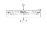
次いで、ST60へ進み、変更処理が終了したときは、本工程を終了する。
次いで、ST60へ進み、変更処理が終了したときは、本工程を終了する。
このように、本実施の形態では、権限ある麻酔科医等に限り、病院管理サーバ300の「薬剤」や「実行モデル」の登録を変更することができるので、極めて、安全性が高いシステムとなっている。
ところで、本発明は、上述の実施の形態に限定されない。本実施の形態では、ラック装置200の上段装着部201a、中段装着部201b、下段装着部201cの全ての送液ポンプ装着部を使用する構成としたが、本発明は全ての送液ポンプ装着部を使用することに限定されるものではない。また、本実施の形態では、ラック装置200の上段装着部201a、中段装着部201b、下段装着部201cに装着されるシリンジポンプ100a等が使用可能な薬剤及び実行モデルの情報を「病院管理サーバ300」が管理する構成としたが、本発明はこれに限らず、例えば、ラック装置200が係る情報を管理しても構わない。
1・・・医療用ポンプシステム、100a、100b、100c・・・シリンジポンプ、101・・・ラック接続用端子、102・・・シリンジ押子、103・・・チューブ、104・・・留置針、105・・・シリンジポンプ側表示部、106・・・操作パネル部、106a・・・電源ON/OFFボタン、106b・・・動作インジケータ、106c・・・早送りスイッチボタン、106d・・・開始スイッチボタン、106e・・・停止スイッチボタン、106f・・・メニュー選択ボタン、108・・・シリンジ,110・・・シリンジポンプ制御部、120・・・第1のシリンジポンプ側各種情報記憶部、121・・・シリンジポンプ側基本情報記憶部、122・・・シリンジポンプ側取得薬剤情報等記憶部,123・・・対応薬剤等判断部(プログラム)、124・・・モデル実行プログラム記憶部、130・・・第2のシリンジポンプ側各種情報記憶部、131・・・シリンジポンプ側患者生体情報記憶部、132・・・シリンジ装着確認部(プログラム)、133・・・確認入力判断部(プログラム)、134・・・モデル実行部(プログラム)、200・・・ラック装置、201a・・・上段装着部、201b・・・中段装着部、201c・・・下段装着部、202・・・通信ボックス、203・・・ラック側通信装置、203a・・・上部装着部用端子、203b・・・中部装着用端子、203c・・・下部装着用端子、204・・・ラック側通信装置、205・・・ラック側表示部、206・・・ラック側各種情報入力部、210・・・ラック制御部、220・・・ラック側各種情報記憶部、221・・・ポンプ装着部分判断部(プログラム)、222・・・ラック側薬剤等特定部(プログラム)、223・・・ラック側患者情報記憶部、224・・・患者生体情報取得部(プログラム)、225・・・ラック側患者生体情報記憶部、226・・・モデル実行データ提供部、300・・・病院管理サーバ、301・・・サーバ制御部、302・・・サーバ側通信装置、303・・・サーバ側表示装置、304・・・サーバ側各種情報入力装置、305・・・電子カルテデータベース、306・・・職員データベース、307・・・ラック装着薬剤記憶部、308・・・入力職員情報記憶部、309・・・職員情報確認部(プログラム)、P・・・患者
Claims (6)
- 薬剤を対象者に投与する送液ポンプと、
前記送液ポンプを配置可能な送液ポンプ装着部を複数有する送液ポンプ用ラック装置と、
前記送液ポンプ用ラック装置と通信可能に接続されている管理装置と、を備える送液ポンプ管理システムであって、
前記送液ポンプは、薬剤の種類情報である第1薬剤種情報と該第1薬剤情報に対応する少なくとも1つの投与方法に関する情報である対応投与実行工程情報とを記憶する記憶部を有し、
前記送液ポンプ用ラック装置又は前記管理装置は、各前記送液ポンプ装着部に対応させた薬剤の種類情報である第2薬剤種情報を有し、
前記送液ポンプ装着部に装着される送液ポンプの前記第1薬剤情報と、該送液ポンプが装着される前記送液ポンプ装着部に対応する前記第2薬剤種情報とを比較し、前記第2薬剤種情報と一致しない前記第1薬剤種情報に対応する前記対応投与実行情報に従い前記薬剤の投与を実行することを、制限することを特徴とする送液ポンプ管理システム。 - 前記送液ポンプが有する前記対応投与実行工程情報が第1対応投与実行工程情報であり、
前記送液ポンプ用ラック装置又は前記管理装置は、各前記送液ポンプ装着部に対応させた投与方法に関する情報である第2対応投与実行工程情報を有し、
前記送液ポンプ装着部に装着される送液ポンプの前記第1対応投与実行工程情報と、該送液ポンプが装着される前記送液ポンプ装着部に対応する前記第2対応投与実行工程情報とを比較し、前記第2対応投与実行工程情報と一致しない前記第1対応投与実行情報に従い前記薬剤の投与を実行することを、制限することを特徴とする請求項1に記載の送液ポンプ管理システム。 - 前記第1薬剤種情報が、前記第2薬剤種情報と一致しないと判断したときは、その旨を出力する構成となっていることを特徴とする請求項1又は請求項2に記載の送液ポンプ管理システム。
- 前記対応投与実行工程の実行に必要な当該対象者の生体情報を前記送液ポンプに提供する構成となっていることを特徴とする請求項1乃至請求項3のいずれか1項に記載の送液ポンプ管理システム。
- 前記薬剤が、麻酔薬関連薬剤であることを特徴とする請求項1乃至請求項4のいずれか1項に記載の送液ポンプ管理システム。
- 薬剤を対象者に投与する送液ポンプと、
前記送液ポンプを配置可能な送液ポンプ装着部を複数有する送液ポンプ用ラック装置と、
前記送液ポンプ用ラック装置と通信可能に接続されている管理装置と、を備える送液ポンプ管理システムであって、
前記送液ポンプは、投与方法に関する情報である第1対応投与実行工程情報を記憶する記憶部を有し、
前記送液ポンプ用ラック装置又は前記管理装置は、各前記送液ポンプ装着部に対応させた投与方法に関する情報である第2対応投与実行工程情報を有し、
前記送液ポンプ装着部に装着される送液ポンプの前記第1対応投与実行工程情報と、該送液ポンプが装着される前記送液ポンプ装着部に対応する前記第2対応投与実行工程情報とを比較し、前記第2対応投与実行工程情報と一致しない前記第1対応投与実行情報に従い前記薬剤の投与を実行することを、制限することを特徴とする送液ポンプ管理システム。
Priority Applications (1)
| Application Number | Priority Date | Filing Date | Title |
|---|---|---|---|
| JP2017509178A JP6698071B2 (ja) | 2015-03-27 | 2015-12-24 | 送液ポンプ管理システム |
Applications Claiming Priority (2)
| Application Number | Priority Date | Filing Date | Title |
|---|---|---|---|
| JP2015-066861 | 2015-03-27 | ||
| JP2015066861 | 2015-03-27 |
Publications (1)
| Publication Number | Publication Date |
|---|---|
| WO2016157655A1 true WO2016157655A1 (ja) | 2016-10-06 |
Family
ID=57006857
Family Applications (1)
| Application Number | Title | Priority Date | Filing Date |
|---|---|---|---|
| PCT/JP2015/086030 WO2016157655A1 (ja) | 2015-03-27 | 2015-12-24 | 送液ポンプ管理システム |
Country Status (2)
| Country | Link |
|---|---|
| JP (1) | JP6698071B2 (ja) |
| WO (1) | WO2016157655A1 (ja) |
Cited By (4)
| Publication number | Priority date | Publication date | Assignee | Title |
|---|---|---|---|---|
| WO2019064953A1 (ja) * | 2017-09-29 | 2019-04-04 | テルモ株式会社 | 医療用ポンプ、医療用ポンプの制御方法、及び医療用ポンプシステム |
| WO2019064952A1 (ja) * | 2017-09-29 | 2019-04-04 | テルモ株式会社 | 医療用ポンプ、医療用ポンプの制御方法、及び医療用ポンプシステム |
| CN112313753A (zh) * | 2018-04-26 | 2021-02-02 | 康尔福盛303公司 | 半自主热切换式输注模块 |
| JP7555626B2 (ja) | 2022-03-07 | 2024-09-25 | 株式会社根本杏林堂 | 薬液注入装置、薬液注入装置の動作方法及びプログラム |
Citations (2)
| Publication number | Priority date | Publication date | Assignee | Title |
|---|---|---|---|---|
| JP2008167888A (ja) * | 2007-01-11 | 2008-07-24 | Terumo Corp | 医療用ポンプシステム |
| WO2014033779A1 (ja) * | 2012-08-29 | 2014-03-06 | テルモ株式会社 | 輸液ポンプのラック装置 |
Family Cites Families (3)
| Publication number | Priority date | Publication date | Assignee | Title |
|---|---|---|---|---|
| NZ542646A (en) * | 2003-03-28 | 2008-10-31 | Cardinal Health 303 Inc | Infusion data communication system |
| JP5113742B2 (ja) * | 2005-05-10 | 2013-01-09 | ケアフュージョン 303、インコーポレイテッド | 多重化rfid質問機パネルを備える投薬安全システム |
| US8894631B2 (en) * | 2010-03-24 | 2014-11-25 | Baxter International Inc. | Multiple drug infusion system and method |
-
2015
- 2015-12-24 JP JP2017509178A patent/JP6698071B2/ja active Active
- 2015-12-24 WO PCT/JP2015/086030 patent/WO2016157655A1/ja active Application Filing
Patent Citations (2)
| Publication number | Priority date | Publication date | Assignee | Title |
|---|---|---|---|---|
| JP2008167888A (ja) * | 2007-01-11 | 2008-07-24 | Terumo Corp | 医療用ポンプシステム |
| WO2014033779A1 (ja) * | 2012-08-29 | 2014-03-06 | テルモ株式会社 | 輸液ポンプのラック装置 |
Cited By (11)
| Publication number | Priority date | Publication date | Assignee | Title |
|---|---|---|---|---|
| WO2019064953A1 (ja) * | 2017-09-29 | 2019-04-04 | テルモ株式会社 | 医療用ポンプ、医療用ポンプの制御方法、及び医療用ポンプシステム |
| WO2019064952A1 (ja) * | 2017-09-29 | 2019-04-04 | テルモ株式会社 | 医療用ポンプ、医療用ポンプの制御方法、及び医療用ポンプシステム |
| JPWO2019064953A1 (ja) * | 2017-09-29 | 2020-09-10 | テルモ株式会社 | 医療用ポンプ、医療用ポンプの制御方法、及び医療用ポンプシステム |
| JP7183169B2 (ja) | 2017-09-29 | 2022-12-05 | テルモ株式会社 | 医療用ポンプ、医療用ポンプの制御方法、及び医療用ポンプシステム |
| US11617830B2 (en) | 2017-09-29 | 2023-04-04 | Terumo Kabushiki Kaisha | Medical pump, method of controlling medical pump, and medical pump system |
| CN112313753A (zh) * | 2018-04-26 | 2021-02-02 | 康尔福盛303公司 | 半自主热切换式输注模块 |
| JP2021521979A (ja) * | 2018-04-26 | 2021-08-30 | ケアフュージョン 303、インコーポレイテッド | 半自律的なホットスワップ注入モジュール |
| US11738141B2 (en) | 2018-04-26 | 2023-08-29 | Carefusion 303, Inc. | Semi-autonomous hot-swap infusion module |
| JP7352571B2 (ja) | 2018-04-26 | 2023-09-28 | ケアフュージョン 303、インコーポレイテッド | 半自律的なホットスワップ注入モジュール |
| CN112313753B (zh) * | 2018-04-26 | 2024-06-04 | 康尔福盛303公司 | 半自主热切换式输注模块 |
| JP7555626B2 (ja) | 2022-03-07 | 2024-09-25 | 株式会社根本杏林堂 | 薬液注入装置、薬液注入装置の動作方法及びプログラム |
Also Published As
| Publication number | Publication date |
|---|---|
| JPWO2016157655A1 (ja) | 2018-01-18 |
| JP6698071B2 (ja) | 2020-05-27 |
Similar Documents
| Publication | Publication Date | Title |
|---|---|---|
| JP5230205B2 (ja) | 未決投薬指令の管理方法 | |
| US8894631B2 (en) | Multiple drug infusion system and method | |
| JP5762500B2 (ja) | 血糖値を監視及び調整するシステム及びその作動方法 | |
| US9597448B2 (en) | Computer-controlled intravenous drug delivery system | |
| KR101506230B1 (ko) | 자가-투여 주사 장치 | |
| WO2016157655A1 (ja) | 送液ポンプ管理システム | |
| EP1408436A1 (en) | Patient information management apparatus and method | |
| TW202138968A (zh) | 具有安全序列鍵盤之輸液泵 | |
| US8038642B2 (en) | System for delivering anesthesia drugs to a patient | |
| US20130085471A1 (en) | System and Method for Monitoring Time Intervals During Blood Parameter Monitoring | |
| AU2003267213A1 (en) | Drug delivery system and method | |
| KR102328988B1 (ko) | 환자 관리 장치-특이적 구성 출력 | |
| US20080108970A1 (en) | Control of Drug Administration | |
| Engbers | Practical use of ‘Diprifusor’systems | |
| JP5851512B2 (ja) | 薬剤情報管理装置及び薬剤情報管理方法 | |
| KR101918694B1 (ko) | 인퓨전 펌프를 이용하여 환자에게 약물을 주입하기 위한 인터페이스를 제공하는 방법, 서버 및 컴퓨터 판독 가능한 기록 매체 | |
| CN113948182A (zh) | 一种自动化智能精准输注及数据处理系统 | |
| KR101888489B1 (ko) | 인퓨전 펌프를 이용하여 환자에게 약물을 주입하는 방법, 서버 및 컴퓨터 판독 가능한 기록 매체 | |
| WO2024145190A1 (en) | Pca pump programming and patient history user interface | |
| CN109276775A (zh) | 一种智能自控给药方法及设备 | |
| WO2014162487A1 (ja) | 医療情報管理装置、医療情報管理システム及び医療情報管理装置の制御方法 | |
| WO2024145183A1 (en) | Automatic syringe pump near empty alarm activation threshold programming | |
| CN105074767B (zh) | 医疗信息管理装置、医疗信息管理系统及医疗信息管理装置的控制方法 | |
| WO2014162485A1 (ja) | 医療情報管理システム及び医療情報管理方法 | |
| Thornton | Medication safety series |
Legal Events
| Date | Code | Title | Description |
|---|---|---|---|
| 121 | Ep: the epo has been informed by wipo that ep was designated in this application |
Ref document number: 15887797 Country of ref document: EP Kind code of ref document: A1 |
|
| ENP | Entry into the national phase |
Ref document number: 2017509178 Country of ref document: JP Kind code of ref document: A |
|
| NENP | Non-entry into the national phase |
Ref country code: DE |
|
| 122 | Ep: pct application non-entry in european phase |
Ref document number: 15887797 Country of ref document: EP Kind code of ref document: A1 |