WO2016157648A1 - 加工治具およびスパッタリングターゲット材の製造方法 - Google Patents
加工治具およびスパッタリングターゲット材の製造方法 Download PDFInfo
- Publication number
- WO2016157648A1 WO2016157648A1 PCT/JP2015/085687 JP2015085687W WO2016157648A1 WO 2016157648 A1 WO2016157648 A1 WO 2016157648A1 JP 2015085687 W JP2015085687 W JP 2015085687W WO 2016157648 A1 WO2016157648 A1 WO 2016157648A1
- Authority
- WO
- WIPO (PCT)
- Prior art keywords
- cylindrical
- cylindrical ceramic
- outer peripheral
- processing
- peripheral surface
- Prior art date
- Legal status (The legal status is an assumption and is not a legal conclusion. Google has not performed a legal analysis and makes no representation as to the accuracy of the status listed.)
- Ceased
Links
Images



Classifications
-
- B—PERFORMING OPERATIONS; TRANSPORTING
- B24—GRINDING; POLISHING
- B24B—MACHINES, DEVICES, OR PROCESSES FOR GRINDING OR POLISHING; DRESSING OR CONDITIONING OF ABRADING SURFACES; FEEDING OF GRINDING, POLISHING, OR LAPPING AGENTS
- B24B41/00—Component parts such as frames, beds, carriages, headstocks
- B24B41/06—Work supports, e.g. adjustable steadies
-
- C—CHEMISTRY; METALLURGY
- C04—CEMENTS; CONCRETE; ARTIFICIAL STONE; CERAMICS; REFRACTORIES
- C04B—LIME, MAGNESIA; SLAG; CEMENTS; COMPOSITIONS THEREOF, e.g. MORTARS, CONCRETE OR LIKE BUILDING MATERIALS; ARTIFICIAL STONE; CERAMICS; REFRACTORIES; TREATMENT OF NATURAL STONE
- C04B35/00—Shaped ceramic products characterised by their composition; Ceramics compositions; Processing powders of inorganic compounds preparatory to the manufacturing of ceramic products
-
- C—CHEMISTRY; METALLURGY
- C23—COATING METALLIC MATERIAL; COATING MATERIAL WITH METALLIC MATERIAL; CHEMICAL SURFACE TREATMENT; DIFFUSION TREATMENT OF METALLIC MATERIAL; COATING BY VACUUM EVAPORATION, BY SPUTTERING, BY ION IMPLANTATION OR BY CHEMICAL VAPOUR DEPOSITION, IN GENERAL; INHIBITING CORROSION OF METALLIC MATERIAL OR INCRUSTATION IN GENERAL
- C23C—COATING METALLIC MATERIAL; COATING MATERIAL WITH METALLIC MATERIAL; SURFACE TREATMENT OF METALLIC MATERIAL BY DIFFUSION INTO THE SURFACE, BY CHEMICAL CONVERSION OR SUBSTITUTION; COATING BY VACUUM EVAPORATION, BY SPUTTERING, BY ION IMPLANTATION OR BY CHEMICAL VAPOUR DEPOSITION, IN GENERAL
- C23C14/00—Coating by vacuum evaporation, by sputtering or by ion implantation of the coating forming material
- C23C14/22—Coating by vacuum evaporation, by sputtering or by ion implantation of the coating forming material characterised by the process of coating
- C23C14/34—Sputtering
Definitions
- the disclosed embodiment relates to a processing jig and a method for manufacturing a sputtering target material.
- a sputtering apparatus in which a magnetic field generator is arranged inside a cylindrical target material, and a thin film is formed on a substrate by performing sputtering while rotating the target material while cooling it from the inside.
- the above-described cylindrical target material is manufactured, for example, by grinding cylindrical ceramics that are fired bodies. Specifically, for example, while rotating a cylindrical ceramic, the inner peripheral surface and the outer peripheral surface are ground with a grindstone, and the dimensions of the inner diameter and the outer diameter are adjusted to produce a cylindrical target material.
- the above processing jig has room for further improvement in terms of suppressing the occurrence of scratches and cracks in the cylindrical ceramics.
- cylindrical ceramic is a brittle material with relatively low mechanical strength, when the outer peripheral surface is held by a processing jig as described above, deep scratches or There was a risk of cracking. Since cylindrical ceramics with such scratches and cracks cannot be used as sputtering target materials, there is a problem that the yield of cylindrical ceramics for sputtering target materials is reduced.
- One aspect of the embodiments has been made in view of the above, and an object thereof is to provide a processing jig and a sputtering target material manufacturing method capable of suppressing generation of scratches and cracks in cylindrical ceramics. To do.
- the processing jig includes a rotating body that rotates following the rotation of the cylindrical ceramics.
- the length of the rotating body in the rotation axis direction is 15 mm or more, and the material of at least the outer peripheral portion of the rotating body is a resin having a Rockwell hardness of 80 or more and 125 or less, or a rubber hardness of 80 or more and 95 or less. Of rubber.
- the generation of scratches and cracks in the cylindrical ceramics can be suppressed.
- FIG. 1 is a cross-sectional view illustrating a configuration example of a processing apparatus including the processing jig according to the first embodiment.
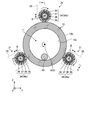
- FIG. 2 is a cross-sectional view of the vicinity of the processing jig shown in FIG. 1 when viewed from the longitudinal direction side of the cylindrical ceramic.
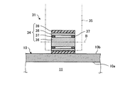
- FIG. 3 is an enlarged cross-sectional view of the processing jig shown in FIG.
- FIG. 4 is a flowchart showing a processing procedure for manufacturing the sputtering target material.
- FIG. 5 is an enlarged cross-sectional view showing a processing jig according to the second embodiment.
- FIG. 1 is a cross-sectional view illustrating a configuration example of a processing apparatus including the processing jig according to the first embodiment.
- 2 is a cross-sectional view of the vicinity of the processing jig shown in FIG. 1 when viewed from the longitudinal direction side of the cylindrical ceramic.
- FIG. 1 shows a cross section when the processing apparatus is cut along the line II in FIG.
- FIG. 2 for easy understanding, a three-dimensional orthogonal coordinate system in which the X-axis direction, the Y-axis direction, and the Z-axis direction orthogonal to each other are defined and the Z-axis positive direction is the vertical upward direction is shown. It is shown.
- FIGS. 1 and 2 and FIGS. 3 and 5 are schematic diagrams.
- a processing apparatus 1 shown in FIG. 1 is an apparatus for processing a long cylindrical ceramic 10 to produce a sputtering target material.
- the target material manufactured using the processing apparatus 1 is set in a sputtering apparatus (not shown), and sputtering for forming a thin film on a substrate (not shown) is performed.
- the cylindrical ceramic 10 is formed in a cylindrical shape having a hollow portion 11.
- the cylindrical ceramic 10 is manufactured through a granulation process, a forming process, and a firing process.
- a slurry containing a ceramic raw material powder and an organic additive is prepared, and a granule is prepared by spray drying the slurry.
- the granules are formed, for example, by CIP (Cold Isostatic Pressing) to produce a cylindrical shaped body.
- the firing step the molded body is fired in a firing furnace to produce a fired body.
- the fired body produced in this manner is a cylindrical ceramic 10, and the cylindrical ceramic 10 is subjected to grinding on the inner peripheral surface 10 a while being rotated by the processing apparatus 1.
- the production method of the cylindrical ceramics 10 which is a sintered body is not limited to the above-described method, and any method may be used.
- CIP molding is used.
- the present invention is not limited to this, and other molding techniques such as extrusion molding, injection molding, and casting molding may be used.
- the ceramic raw material of the cylindrical ceramic 10 examples include IGZO (In 2 O 3 —Ga 2 O 3 —ZnO), ITO (In 2 O 3 —SnO 2 ), and AZO (Al 2 O 3 —ZnO).
- IGZO In 2 O 3 —Ga 2 O 3 —ZnO
- ITO In 2 O 3 —SnO 2
- AZO Al 2 O 3 —ZnO
- the cylindrical ceramic 10 may include one or more of In, Zn, Al, Ga, Zr, Ti, Sn, Mg, and Si, for example.
- the cylindrical ceramic 10 manufactured in this way has a longer total length, the force applied to the contact portion between the processing jig and the cylindrical ceramic 10 increases.
- the total length is 500 mm or more, preferably 750 mm or more, more preferably. In the case of 1000 mm or more, it is appropriate to apply a processing jig described later. However, a processing jig may be used for the cylindrical ceramics 10 having a total length of less than 500 mm.
- the processing apparatus 1 includes a rotation mechanism 20 and a vibration suppression mechanism 30.
- the rotation mechanism 20 rotates the cylindrical ceramic 10 while holding the one end 10 c of the cylindrical ceramic 10.
- the rotation mechanism 20 includes a main body portion 21, a rotation portion 22, and a holding claw 23.
- the main body 21 accommodates a drive source (not shown) such as a motor that rotationally drives the rotating unit 22.
- the rotating unit 22 is connected to the output shaft of the drive source described above, and rotates around the rotation axis A when a rotational force is transmitted from the drive source.
- the holding claws 23 are connected to the rotating portion 22 and are arranged on the outer peripheral side of the one end 10 c of the cylindrical ceramic 10 to hold the cylindrical ceramic 10.
- each of the three holding claws 23 is configured to be independently movable in the radial direction of the cylindrical ceramic 10 in the X-axis direction view.
- the space surrounded by the three holding claws 23 is set in advance so as to be larger than the outer diameter of the cylindrical ceramics 10 when viewed in the X-axis direction. Keep it. Then, after one end 10c of the cylindrical ceramic 10 is set in a space surrounded by the three holding claws 23, the three holding claws 23 are respectively moved radially inward.
- the one end 10 c of the cylindrical ceramic 10 is held by the three holding claws 23 by bringing the holding claw 23 into contact with the outer peripheral surface 10 b of the cylindrical ceramic 10 with a predetermined pressure.
- the rotation mechanism 20 can rotate the cylindrical ceramics 10 held by the holding claws 23 around the rotation axis A along with the rotation of the rotating unit 22.
- rotational axis of the cylindrical ceramic 10 is substantially coaxial with the rotational axis A of the rotation mechanism 20. Therefore, in FIG. 1 and the like, the rotation axis of the cylindrical ceramics 10 is also illustrated as “rotation axis A” for simplification of illustration. In the following, “rotation axis A” may be used to mean the rotation axis A of the cylindrical ceramic 10.
- the holding claws 23 of the rotation mechanism 20 are three, but the number is not limited to this.
- the cylindrical ceramics 10 are held by the holding claws 23.
- the rotation mechanism 20 includes a holding portion formed in a ring shape instead of the holding claw 23, and is inserted into the holding portion with one end 10c of the cylindrical ceramic 10 and fixed in another configuration. The ceramic 10 may be held.
- the vibration suppressing mechanism 30 rotatably holds the vicinity of the other end 10d of the cylindrical ceramic 10 and suppresses vibration of the cylindrical ceramic 10 caused by the rotation. Thereby, since the rotating shaft A of the rotating cylindrical ceramic 10 is stabilized, the grinding accuracy at the time of the grinding process mentioned later can be improved.
- the vibration suppression mechanism 30 includes a main body (not shown) and a processing jig 31.
- the processing jig 31 is provided in the main body, and holds the vicinity of the other end 10d of the cylindrical ceramic 10 so as to be rotatable from the outer peripheral surface 10b side.
- the cylindrical ceramic 10 is a brittle material having a relatively low mechanical strength. Therefore, for example, when the portion that contacts the cylindrical ceramics 10 in the processing jig 31 is made of a metal such as stainless steel, deep scratches or cracks may occur on the outer peripheral surface 10 b due to contact with the processing jig 31. .
- the processing jig 31 according to the present embodiment is configured such that the occurrence of scratches and cracks in the cylindrical ceramic 10 can be suppressed.
- the configuration of the processing jig 31 will be described in more detail.
- FIG. 3 is an enlarged cross-sectional view of the processing jig 31 shown in FIG. As shown in FIG. 2 and the like, the processing jig 31 includes a plurality of rollers 34 and a support portion 35 that supports the plurality of rollers 34. 1 to 3, the support portion 35 is indicated by an imaginary line for simplification of illustration.
- the roller 34 is formed in a columnar shape, for example.
- the roller 34 is an example of a rotating body.
- the plurality of rollers 34 are arranged on the outer peripheral side near the other end 10d of the cylindrical ceramic 10.
- the number of rollers 34 is three (one is not visible in FIG. 1), and they are arranged at an interval of 120 degrees around the rotation axis A of the cylindrical ceramic 10.
- the rollers 34 are arranged at equal intervals (for example, intervals of 120 degrees).
- this is only an example and is not limited, and the intervals between the plurality of rollers 34 are arbitrarily set. be able to.
- Each of the plurality of rollers 34 described above is provided in contact with the outer peripheral surface 10b of the cylindrical ceramic 10 that rotates in the circumferential direction, and thus rotates around the rotation axis B following the rotation of the cylindrical ceramic 10. Configured as follows.
- the roller 34 includes a core member 36, a bearing 37, an inner peripheral portion 38, and an outer peripheral portion 39.
- the core member 36 is formed in a columnar shape, for example, and is fixed at an appropriate position of the support portion 35. Further, as the core material 36, for example, a metal material such as iron, stainless steel, titanium, and a titanium alloy, hard rubber, or resin can be used, but is not limited thereto.
- a metal material such as iron, stainless steel, titanium, and a titanium alloy, hard rubber, or resin can be used, but is not limited thereto.
- the inner peripheral portion 38 is formed in a cylindrical shape, for example, and is provided at a position surrounding the core member 36 when viewed in the direction of the rotation axis B. Further, the bearing 37 is interposed between the core member 36 and the inner peripheral portion 38. In other words, the bearing 37 is disposed on the radially outer side of the core member 36 and on the radially inner side of the inner peripheral portion 38. Therefore, the bearing 37 supports the inner peripheral portion 38 and the outer peripheral portion 39 so as to be rotatable with respect to the core member 36.
- the bearings 37 are arranged in the vicinity of both ends of the core member 36.
- the present invention is not limited to this, and the arrangement location and number of the bearings 37 are arbitrary. It can be set.
- the inner peripheral portion 38 may be made of, for example, a metal material such as iron, stainless steel, titanium, and a titanium alloy, hard rubber, or resin, but these are examples and are not limited.
- the outer peripheral portion 39 is formed so as to cover the radially outer surface of the inner peripheral portion 38 and is formed in a cylindrical shape. Further, the outer peripheral portion 39 is disposed so as to contact the outer peripheral surface 10 b of the cylindrical ceramic 10.
- the material of the outer peripheral portion 39 that contacts the cylindrical ceramic 10 is resin or rubber.
- resin although the resin material containing 1 or more types among polyamide resin, ABS resin, polycarbonate resin, polypropylene resin, etc. can be used, it is not limited to these.
- rubber a rubber material including one or more of chloroprene rubber, nitrile rubber, natural rubber, isoprene rubber, butadiene rubber, urethane rubber and the like can be used, but is not limited thereto. .
- the material of the outer peripheral part 39 since the material of the outer peripheral part 39 was resin or rubber, it acts on the cylindrical ceramics 10 from the roller 34 at the time of contact compared with the case where the outer peripheral part 39 is temporarily metal.
- the load can be reduced.
- the outer peripheral surface 10b of the cylindrical ceramic 10 is damaged or cracked by contact with the roller 34. This can be suppressed.
- the length L1 (see FIG. 1) of the roller 34 configured as described above in the direction of the rotation axis B is preferably, for example, 15 mm or more, more preferably 30 mm or more, and further preferably 50 mm or more. That is, by setting the total length L1 of the roller 34 so as to increase the contact area between the roller 34 and the cylindrical ceramic 10, the surface pressure acting on the cylindrical ceramic 10 from the roller 34 at the time of contact can be reduced. . Thereby, it can suppress effectively that a crack and a crack generate
- the upper limit of the length L1 of the roller 34 in the direction of the rotation axis B is not particularly limited, but is preferably 5000 mm or less in terms of handling work in the process using the roller 34.
- the ratio of the total length L1 in the rotation axis B direction of the roller 34 to the total length L2 (see FIG. 1) in the rotation axis A direction of the cylindrical ceramic 10 is preferably 3% or more, more preferably 5% or more.
- the Rockwell hardness ASTM standard, D785, R scale
- ASTM standard, D785, R scale is, for example, preferably 80 or more and 125 or less, and more preferably 80 or more and 120 or less.
- the rubber hardness JIS standard, K6253-3: 2012 is preferably 80 or more and 95 or less, and more preferably 80 or more and 90 or less.
- the load which acts on the cylindrical ceramics 10 from the roller 34 at the time of contact can further be reduced, and the outer peripheral surface 10b of the cylindrical ceramics 10 is damaged. And the occurrence of cracks can be suppressed. If the hardness is higher than the above range, scratches and cracks may occur on the outer peripheral surface 10b of the cylindrical ceramic 10, and if the hardness is lower than the above range, vibrations cannot be suppressed and processing accuracy may deteriorate.
- the position where the roller 34 abuts against the cylindrical ceramic 10 is other than the position C1 (see FIG. 1) of 1 ⁇ 2 of the total length L2 from one end 10c of the cylindrical ceramic 10 held by the rotating mechanism 20, for example.
- the end 10d side is preferable.
- the position of the roller 34 is closer to the other end 10d than the position C2 (see FIG. 1) of 2/3 of the total length L2 from the one end 10c of the cylindrical ceramic 10.
- the cylindrical ceramics 10 can be stably held, and vibrations of the cylindrical ceramics 10 can be further suppressed. Furthermore, since the rotation axis A of the rotating cylindrical ceramic 10 is stabilized, the grinding accuracy can be further improved.
- the support part 35 supports the three rollers 34 as described above.
- Each of the three support portions 35 is attached to a main body (not shown) of the vibration suppressing mechanism 30 and is configured to be independently movable in the radial direction of the cylindrical ceramic 10 when viewed in the X-axis direction.
- the space surrounded by the three rollers 34 in the X-axis direction view is larger than the outer diameter of the cylindrical ceramic 10 in advance. Set it to be larger. Then, after the vicinity of the other end 10d of the cylindrical ceramic 10 is set in a space surrounded by the three rollers 34, the three support portions 35 and the rollers 34 are respectively moved radially inward.
- the processing apparatus 1 includes a grindstone 40 (see FIGS. 1 and 2).
- the grindstone 40 moves while contacting the inner peripheral surface 10a in the hollow portion 11 of the cylindrical ceramic 10 by a moving mechanism (not shown). That is, in the processing apparatus 1, traverse grinding is performed on the inner peripheral surface 10 a of the cylindrical ceramic 10.
- the grinding method of the internal peripheral surface 10a of the cylindrical ceramics 10 is not limited to traverse grinding, and any method may be used.
- the number of rollers 34 is three, but the number is not limited to this. In the above example, all the plurality of rollers 34 have the same configuration. However, the present invention is not limited to this. For example, some or all of the plurality of rollers 34 may have different configurations.
- the portion of the cylindrical ceramic 10 that contacts the roller 34a has a higher load than the portion that contacts the roller 34b, and scratches and cracks occur. It is likely to occur.
- the material of only the outer peripheral portion 39 of the two rollers 34a may be made of resin or rubber.
- the total length L1 of the two rollers 34a may be configured to be longer than the total length L1 of the roller 34b.
- the outer peripheral surface 10b of the cylindrical ceramic 10 is not damaged or cracked. Generation
- production can be suppressed.
- FIG. 4 is a flowchart showing a processing procedure for manufacturing the sputtering target material.
- the cylindrical ceramic 10 is attached to the rotating mechanism 20 by holding one end 10c of the cylindrical ceramic 10 with the holding claw 23 of the rotating mechanism 20 (step S1).
- step S2 the other end 10d of the cylindrical ceramic 10 is rotatably held by the roller 34 of the processing jig 31 (step S2).
- the order of the processes in steps S1 and S2 is not limited to the above.
- the process in step S1 may be performed after the process in step S2, and furthermore, the processes in steps S1 and S2 are performed at the same timing. It may be done at.
- the cylindrical ceramic 10 is rotated in the circumferential direction by the rotation mechanism 20 to grind the inner peripheral surface 10a (step S3).
- the processing of the inner peripheral surface 10a of the series of cylindrical ceramics 10 is completed.
- steps S1 to S3 may be performed in manufacturing the sputtering target material. For example, you may make it perform the process which grinds the outer peripheral surface 10b of the cylindrical ceramics 10. FIG.
- the processing jig 31 includes the roller (rotating body) 34 that rotates following the rotation of the cylindrical ceramics 10.
- the length of the roller 34 in the rotation axis direction is 15 mm or more, and the material of at least the outer peripheral portion 39 of the roller 34 is a resin having a Rockwell hardness of 80 or more and 125 or less or a rubber having a rubber hardness of 80 or more and 95 or less. is there. Thereby, generation
- the cylindrical ceramics 10 in which the generation of scratches and cracks is suppressed as described above can be used as a sputtering target material, in this embodiment, the yield reduction of the cylindrical ceramics for the sputtering target material is also suppressed. can do.
- Example 1 BET (Brunauer-Emmett-Teller) and 25.9 wt% ZnO powder measured specific surface area (BET specific surface area) of 4m 2 / g by a method, BET specific surface area of 7m 2 / g of In 2 O 3 powder 44 2% by mass and 29.9% by mass of Ga 2 O 3 powder having a BET specific surface area of 10 m 2 / g were mixed in a ball mill with zirconia balls in a pot to prepare a raw material powder.
- BET Brunauer-Emmett-Teller
- this slurry was supplied to a spray drying apparatus, and spray drying was performed under the conditions of an atomizer rotational speed of 14,000 rpm, an inlet temperature of 200 ° C., and an outlet temperature of 80 ° C. to prepare granules.
- the granules were filled while being tapped into a cylindrical urethane rubber mold having an inner diameter of 220 mm (thickness 10 mm) having a cylindrical core (mandrel) having an outer diameter of 150 mm and a length of 1300 mm, and after sealing the rubber mold, CIP molding was performed at a pressure of 800 kgf / cm 2 to produce a cylindrical molded body.
- This molded body was heated to 1400 ° C. at a temperature rising rate of 300 ° C./h from normal temperature, held for 12 hours, and then cooled at a temperature lowering rate of 50 ° C./h to fire the molded body to produce a fired body. . Then, the fired body produced by the above method was cut so that the total length L2 was 500 mm to obtain a cylindrical ceramic 10 of IGZO.
- the processing jig 31 which has the roller 34 whose material of the outer peripheral part 39 is a polyamide resin, the full length L1 is 15 mm, and Rockwell hardness is 120 is used.
- the inner peripheral surface 10a was ground. No cracks or cracks were observed on the outer peripheral surface 10b of the cylindrical ceramic 10 after processing, and the depth of scratches after processing was 0.4 mm.
- Example 2 A fired body produced by the same method as in Example 1 was cut so that the total length L2 was 1000 mm, whereby a cylindrical ceramic 10 was obtained. And after grind-processing the outer peripheral surface 10b with respect to this cylindrical ceramic 10, using the processing jig 31 which has the roller 34 whose material of the outer peripheral part 39 is a polyamide resin, the full length L1 is 60 mm, and Rockwell hardness is 120. The inner peripheral surface 10a was ground. No cracks or cracks were observed on the outer peripheral surface 10b of the cylindrical ceramic 10 after processing, and the depth of scratches after processing was 0.2 mm.
- Example 3 A fired body produced by the same method as in Example 1 was cut so that the total length L2 was 1000 mm, whereby a cylindrical ceramic 10 was obtained. And after grind-processing the outer peripheral surface 10b with respect to this cylindrical ceramic 10, using the processing jig 31 which has the roller 34 whose material of the outer peripheral part 39 is a polypropylene resin, the full length L1 is 60 mm, and Rockwell hardness is 81. The inner peripheral surface 10a was ground. Cracks and cracks were not confirmed on the outer peripheral surface 10b of the cylindrical ceramic 10 after processing, and the depth of the scratch after processing was 0.3 mm.
- Example 4 A pot containing 10% by mass of SnO 2 powder having a specific surface area (BET specific surface area) of 5 m 2 / g measured by the BET method and 90% by mass of In 2 O 3 powder having a BET specific surface area of 5 m 2 / g,
- the raw material powder was prepared by ball mill mixing with zirconia balls.
- Example 2 The subsequent steps from spray drying to molding were the same as in Example 1.
- the obtained molded body was heated to 1600 ° C. at a temperature rising rate of 300 ° C./h from normal temperature, held for 12 hours, and then cooled at a temperature lowering rate of 50 ° C./h to fire the molded body.
- This fired body was cut so that the total length L2 was 1000 mm, and an ITO cylindrical ceramic 10 was obtained.
- the outer peripheral surface 39 is made of a polyamide resin, the length L1 is 60 mm, and the rockwell hardness is 120.
- the inner peripheral surface 10a was ground. No cracks or cracks were observed on the outer peripheral surface 10b of the cylindrical ceramic 10 after processing, and the depth of scratches after processing was 0.1 mm.
- Example 5 A fired body produced by the same method as in Example 4 was cut so that the total length L2 was 1000 mm, whereby a cylindrical ceramic 10 was obtained. And after grind-processing the outer peripheral surface 10b with respect to this cylindrical ceramic 10, using the processing jig 31 which has the roller 34 whose material of the outer peripheral part 39 is polycarbonate resin, the full length L1 is 60 mm, and Rockwell hardness is 125. The inner peripheral surface 10a was ground. No cracks or cracks were observed on the outer peripheral surface 10b of the cylindrical ceramic 10 after processing, and the depth of scratches after processing was 0.2 mm.
- Example 6 A fired body produced by the same method as in Example 1 was cut so that the total length L2 was 500 mm to obtain a cylindrical ceramic 10. And after grind-processing the outer peripheral surface 10b with respect to this cylindrical ceramic 10, using the processing jig 31 which has the roller 34 whose material of the outer peripheral part 39 is chloroprene rubber, total length L1 is 15 mm, and rubber hardness is 90, The inner peripheral surface 10a was ground. No cracks or cracks were observed on the outer peripheral surface 10b of the cylindrical ceramic 10 after processing, and the depth of scratches after processing was 0.4 mm.
- Example 7 A fired body produced by the same method as in Example 1 was cut so that the total length L2 was 1000 mm, whereby a cylindrical ceramic 10 was obtained. And after grind-processing the outer peripheral surface 10b with respect to this cylindrical ceramic 10, using the processing jig 31 which has the roller 34 whose material of the outer peripheral part 39 is chloroprene rubber, the full length L1 is 60 mm, and rubber hardness is 90, The inner peripheral surface 10a was ground. No cracks or cracks were observed on the outer peripheral surface 10b of the cylindrical ceramic 10 after processing, and the depth of scratches after processing was 0.2 mm.
- Example 8 A fired body produced by the same method as in Example 4 was cut so that the total length L2 was 1000 mm, whereby a cylindrical ceramic 10 was obtained. And after grinding the outer peripheral surface 10b with respect to this cylindrical ceramics 10, using the processing jig 31 which has the roller 34 whose material of the outer peripheral part 39 is butadiene rubber, the full length L1 is 60 mm, and rubber hardness is 82, The inner peripheral surface 10a was ground. Cracks and cracks were not confirmed on the outer peripheral surface 10b of the cylindrical ceramic 10 after processing, and the depth of the scratch after processing was 0.2 mm.
- Example 1 A fired body produced by the same method as in Example 1 was cut so that the total length L2 was 500 mm to obtain a cylindrical ceramic 10. Then, after grinding the outer peripheral surface 10b of the cylindrical ceramic 10, the inner peripheral surface 10a is ground by using the processing jig 31 having the roller 34 whose outer peripheral portion 39 is made of SUS304 and whose total length L1 is 15 mm. Went. Note that SUS304 is considerably harder than the resin and rubber used in the present invention. Although cracks and cracks were not confirmed on the outer peripheral surface 10b of the cylindrical ceramic 10 after processing, the depth of scratches after processing was 0.9 mm.
- Example 2 A fired body produced by the same method as in Example 1 was cut so that the total length L2 was 1000 mm, whereby a cylindrical ceramic 10 was obtained. Then, after grinding the outer peripheral surface 10b of the cylindrical ceramic 10, the inner peripheral surface 10a is ground using the processing jig 31 having the roller 34 having the outer peripheral portion 39 made of SUS304 and the total length L1 of 10 mm. Went. In Comparative Example 2, the outer peripheral surface 10b of the cylindrical ceramic 10 was cracked during processing, and could not be processed. For this reason, the depth of the wound after processing could not be measured.
- Example 3 A fired body produced by the same method as in Example 4 was cut so that the total length L2 was 1000 mm, whereby a cylindrical ceramic 10 was obtained. Then, after grinding the outer peripheral surface 10b of the cylindrical ceramic 10, the inner peripheral surface 10a is ground using the processing jig 31 having the roller 34 having the outer peripheral portion 39 made of SUS304 and the total length L1 of 10 mm. Went. Although cracks and cracks were not confirmed on the outer peripheral surface 10b of the cylindrical ceramic 10 after processing, the depth of scratches after processing was 0.6 mm.
- Example 4 A fired body produced by the same method as in Example 1 was cut so that the total length L2 was 1000 mm, whereby a cylindrical ceramic 10 was obtained. Then, after grinding the outer peripheral surface 10b of the cylindrical ceramic 10, the inner peripheral surface 10a is ground by using the processing jig 31 having the roller 34 having the outer peripheral portion 39 made of SUS304 and the total length L1 of 60 mm. Went. Although cracks and cracks were not confirmed on the outer peripheral surface 10b of the cylindrical ceramic 10 after processing, the depth of scratches after processing was 0.9 mm.
- Example 5 A fired body produced by the same method as in Example 1 was cut so that the total length L2 was 1000 mm, whereby a cylindrical ceramic 10 was obtained. And after grinding the outer peripheral surface 10b with respect to the cylindrical ceramic 10, using the processing jig 31 which has the roller 34 whose material of the outer peripheral part 39 is a polyamide resin, the full length L1 is 10 mm, and Rockwell hardness is 120, The inner peripheral surface 10a was ground. Although cracks and cracks were not confirmed on the outer peripheral surface 10b of the cylindrical ceramic 10 after processing, the depth of scratches after processing was 0.6 mm.
- Example 6 A fired body produced by the same method as in Example 1 was cut so that the total length L2 was 1000 mm, whereby a cylindrical ceramic 10 was obtained. And after grinding the outer peripheral surface 10b with respect to the cylindrical ceramic 10, using the processing jig 31 which has the roller 34 whose material of the outer peripheral part 39 is fluororesin, the full length L1 is 60 mm, and Rockwell hardness is 50, The inner peripheral surface 10a was ground. Although cracks and cracks did not occur on the outer peripheral surface 10b of the cylindrical ceramic 10 during processing, vibration could not be suppressed and processing could not be performed.
- Example 7 A fired body produced by the same method as in Example 1 was cut so that the total length L2 was 1000 mm, whereby a cylindrical ceramic 10 was obtained. And after grinding the outer peripheral surface 10b with respect to the cylindrical ceramic 10, the material of the outer peripheral part 39 is chloroprene rubber, the full length L1 is 60 mm, and rubber hardness is 60 (chloroprene rubber softer than what was used in the Example). The inner peripheral surface 10a was ground using the processing jig 31 having the roller 34. Although cracks and cracks did not occur on the outer peripheral surface 10b of the cylindrical ceramic 10 during processing, vibration could not be suppressed and processing could not be performed.
- the depth of scratches formed on the outer peripheral surface 10b of the cylindrical ceramic 10 after grinding the inner peripheral surface 10a is determined by grinding the outer peripheral surface 10b of the cylindrical ceramic 10 after grinding the inner peripheral surface 10a. Then, the grinding depth required until the scratches disappeared was evaluated.
- the present invention is not effective only for the cylindrical sputtering target material of IGZO and ITO.
- FIG. 5 is an enlarged cross-sectional view similar to FIG. 3, showing the processing jig 131 according to the second embodiment.
- the bearing 37 disposed inside the roller 34 in the first embodiment is removed, and the bearing is provided between the support portion 35 and the core material 136. 137 was inserted.
- the core material 136 is formed so that both ends protrude.
- the core material 36 according to the first embodiment is fixed to the support portion 35
- the core material 136 according to the second embodiment is not fixed to the support portion 35, and is attached to the inner peripheral portion 138. It shall be fixed.
- a bearing 137 is inserted between both ends of the protruding core member 136 and an appropriate position of the support portion 35.
- the bearing 137 is disposed on the radially outer side of the core member 136.
- the bearing 137 supports the core 136, the inner peripheral portion 138, and the outer peripheral portion 139 so as to be rotatable with respect to the support portion 35.
- the diameter of the roller 134 can be reduced as compared with the configuration in which the bearing is incorporated, and the processing jig 131 can be downsized. it can.
- the core member 136 and the inner peripheral portion 138 are separate from each other has been described above. However, they may be integrally formed.
- the shape of the rollers 34 and 134 is a cylindrical shape.
- the shape is not limited to this, and any shape such as a spherical shape may be used as long as the outer peripheral side can contact the cylindrical ceramics 10. Good.
- one place near the other end 10d of the cylindrical ceramic 10 is held by the vibration suppressing mechanism 30, but two or more places may be held by the vibration suppressing mechanism 30.
Landscapes
- Chemical & Material Sciences (AREA)
- Engineering & Computer Science (AREA)
- Organic Chemistry (AREA)
- Ceramic Engineering (AREA)
- Materials Engineering (AREA)
- Mechanical Engineering (AREA)
- Structural Engineering (AREA)
- Manufacturing & Machinery (AREA)
- Chemical Kinetics & Catalysis (AREA)
- Metallurgy (AREA)
- Physical Vapour Deposition (AREA)
- Constituent Portions Of Griding Lathes, Driving, Sensing And Control (AREA)
- Compositions Of Oxide Ceramics (AREA)
Abstract
円筒形セラミックスの外周面における傷や割れの発生を抑制することを課題とする。かかる課題を解決するために、実施形態の一態様に係る加工治具(31,131)は、回転体(34,134)を備える。回転体(34,134)は、円筒形セラミックス(10)の回転に従動して回転する。回転体(34,134)の回転軸方向の長さは15mm以上であり、かつ、回転体(34,134)の少なくとも外周部(39,139)の材質が、ロックウェル硬度が80以上125以下の樹脂、あるいはゴム硬度が80以上95以下のゴムである。
Description
開示の実施形態は、加工治具およびスパッタリングターゲット材の製造方法に関する。
従来、円筒形のターゲット材の内側に磁場発生装置が配置され、かかるターゲット材を内側から冷却しつつ回転させながらスパッタリングを行うことで、基板上に薄膜を形成するスパッタリング装置が知られている。
上記した円筒形ターゲット材は、たとえば焼成体である円筒形セラミックスを研削加工して製造される。具体的には、たとえば円筒形セラミックスを回転させながら、内周面や外周面を砥石で研削し、内径や外径の寸法を調整して円筒形ターゲット材が製造される。
上記した従来技術にあっては、たとえば円筒形セラミックスの内周面を研削加工する際、円筒形セラミックスは、一端側が回転機構によって保持されて回転させられる。一方、円筒形セラミックスの他端側は、外周面が加工治具によって回転可能に保持され、これにより回転によって生じる円筒形セラミックスの振動を抑制し、研削精度を向上させるようにしている(たとえば、特許文献1参照)。
しかしながら、上記した加工治具には、円筒形セラミックスの傷や割れの発生を抑制するという点でさらなる改善の余地があった。
すなわち、円筒形セラミックスは、機械的強度が比較的低くて脆い材料であることから、上記のように外周面を加工治具で保持した場合、加工治具との接触によって外周面に深い傷や割れが発生するおそれがあった。
こうした傷や割れが発生した円筒形セラミックスは、スパッタリングターゲット材として使用することができないため、スパッタリングターゲット材用円筒形セラミックスの歩留り低下につながるという問題がある。
こうした傷や割れが発生した円筒形セラミックスは、スパッタリングターゲット材として使用することができないため、スパッタリングターゲット材用円筒形セラミックスの歩留り低下につながるという問題がある。
実施形態の一態様は、上記に鑑みてなされたものであって、円筒形セラミックスにおける傷や割れの発生を抑制することができる加工治具およびスパッタリングターゲット材の製造方法を提供することを目的とする。
実施形態の一態様に係る加工治具は、円筒形セラミックスの回転に従動して回転する回転体を備える。また、前記回転体の回転軸方向の長さは15mm以上であり、かつ、前記回転体の少なくとも外周部の材質が、ロックウェル硬度が80以上125以下の樹脂、あるいはゴム硬度が80以上95以下のゴムである。
実施形態の一態様によれば、円筒形セラミックスにおける傷や割れの発生を抑制することができる。
以下、添付図面を参照して、本願の開示する加工治具およびスパッタリングターゲット材の製造方法を詳細に説明する。なお、以下に示す実施形態によりこの発明が限定されるものではない。
(第1の実施形態)
図1は、第1の実施形態に係る加工治具を備えた加工装置の構成例を示す断面図である。また、図2は、図1に示す加工治具付近を円筒形セラミックスの長手方向側から見たときの断面図である。
図1は、第1の実施形態に係る加工治具を備えた加工装置の構成例を示す断面図である。また、図2は、図1に示す加工治具付近を円筒形セラミックスの長手方向側から見たときの断面図である。
なお、図1は、正確には、図2のI-I線で加工装置を切断したときの断面を示している。また、図2には、説明を分かり易くするために、互いに直交するX軸方向、Y軸方向およびZ軸方向を規定し、Z軸正方向を鉛直上向き方向とした3次元の直交座標系を図示している。
また、図1,2および後述する図3,5では、説明に必要な構成要素のみを示し、一般的な構成要素についての記載を省略する場合がある。また、図1,2および図3,5は、いずれも模式図である。
図1に示す加工装置1は、長尺状の円筒形セラミックス10を加工してスパッタリングターゲット材を製造するための装置である。なお、加工装置1を用いて製造されたターゲット材は、図示しないスパッタリング装置にセットされ、図示しない基板上に薄膜を形成するスパッタリングが行われる。
図1,2に示すように、円筒形セラミックス10は、中空部11を有する筒状に形成される。なお、円筒形セラミックス10は、造粒工程と、成形工程と、焼成工程とを経て作製される。
具体的には、造粒工程では、たとえばセラミックス原料粉末および有機添加物を含有するスラリーを作製し、かかるスラリーをスプレードライ処理によって顆粒体を作製する。成形工程では、顆粒体をたとえばCIP(Cold Isostatic Pressing)成形して、円筒形の成形体を作製する。そして、焼成工程では、成形体を焼成炉内で焼成して焼成体を作製する。
このようにして作製された焼成体が円筒形セラミックス10であり、かかる円筒形セラミックス10は加工装置1によって回転させられながら、内周面10aに対して研削加工が施される。なお、焼成体である円筒形セラミックス10の作製方法は、上記したものに限定されず、いかなる方法であってもよい。
すなわち、たとえば、上記した成形工程では、CIP成形を用いるようにしたが、これに限られず、押出成形や射出成形、鋳込み成形などその他の成形手法を用いてもよい。
また、円筒形セラミックス10のセラミックス原料としては、IGZO(In2O3-Ga2O3-ZnO)、ITO(In2O3-SnO2)およびAZO(Al2O3-ZnO)などを例示することができるが、これらに限定されない。すなわち、円筒形セラミックス10は、たとえばIn、Zn、Al、Ga、Zr、Ti、Sn、MgおよびSiのうち1種以上を含むものであってもよい。
このようにして作製された円筒形セラミックス10は、全長が長いほど、加工冶具と円筒形セラミックス10との接触部分にかかる力が大きくなるため、たとえば全長が500mm以上、好ましくは750mm以上、より好ましくは1000mm以上の場合に、後述する加工治具を適用することが適当である。但し、全長が500mm未満の円筒形セラミックス10に対して、加工治具を用いてもよい。
図1に示すように、加工装置1は、回転機構20と、振動抑制機構30とを備える。回転機構20は、円筒形セラミックス10の一端10cを保持しつつ、円筒形セラミックス10を回転させる。
詳しくは、回転機構20は、本体部21と、回転部22と、保持爪23とを備える。本体部21には、回転部22を回転駆動させるモータなどの駆動源(図示せず)が収容される。
回転部22は、上記した駆動源の出力軸に接続されるとともに、駆動源から回転力が伝達されると、回転軸A回りに回転する。保持爪23は、回転部22に接続されるとともに、円筒形セラミックス10の一端10cの外周側に複数個配置されて、円筒形セラミックス10を保持する。
具体的には、たとえば、保持爪23は3個であり(図1において1個見えず)、回転軸Aを中心として相互に120度の間隔をおいて配置される。また、3個の保持爪23はそれぞれ、X軸方向視において円筒形セラミックス10の径方向に独立して移動可能に構成される。
従って、たとえば、保持爪23で円筒形セラミックス10を保持する場合、先ず、X軸方向視において3個の保持爪23によって囲まれるスペースが予め円筒形セラミックス10の外径よりも大きくなるように設定しておく。そして、円筒形セラミックス10の一端10cが3個の保持爪23によって囲まれるスペースにセットされた後、3個の保持爪23をそれぞれ径方向内側へ移動させる。
次いで、保持爪23を円筒形セラミックス10の外周面10bに所定の圧力で当接させることで、円筒形セラミックス10の一端10cは、3個の保持爪23によって保持されることとなる。これにより、回転機構20は、保持爪23で保持した円筒形セラミックス10を、回転部22の回転に伴って回転軸A回りに回転させることができる。
なお、円筒形セラミックス10の回転軸は、回転機構20の回転軸Aと略同軸になる。従って、図1等では、図示の簡略化のため、円筒形セラミックス10の回転軸も「回転軸A」として図示した。また、以下においては、「回転軸A」を円筒形セラミックス10の回転軸Aの意味で用いる場合がある。
なお、上記では、回転機構20の保持爪23を3個としたが、個数はこれに限られない。また、上記した回転機構20では、円筒形セラミックス10を保持爪23で保持するようにしたが、これは例示であって限定されるものではない。たとえば、回転機構20が、保持爪23に代えて、リング状に形成された保持部を備え、かかる保持部に円筒形セラミックス10の一端10cを挿通して固定するなど、他の構成で円筒形セラミックス10を保持してもよい。
振動抑制機構30は、円筒形セラミックス10の他端10d付近を回転可能に保持し、回転によって生じる円筒形セラミックス10の振動を抑制する。これにより、回転する円筒形セラミックス10の回転軸Aが安定することから、後述する研削加工の際の研削精度を向上させることができる。
詳しくは、振動抑制機構30は、図示しない本体部と、加工治具31とを備える。加工治具31は、本体部に設けられ、円筒形セラミックス10の他端10d付近を外周面10b側から回転可能に保持する。
ところで、円筒形セラミックス10は、機械的強度が比較的低くて脆い材料である。そのため、たとえば、加工治具31において円筒形セラミックス10と接触する部分がステンレスなどの金属製であった場合、加工治具31との接触によって外周面10bに深い傷や割れが発生するおそれがある。
そこで、本実施形態に係る加工治具31にあっては、円筒形セラミックス10における傷や割れの発生を抑制することができるような構成とした。以下、かかる加工治具31の構成について、さらに詳しく説明する。
図3は、図1に示す加工治具31の拡大断面図である。図2などに示すように、加工治具31は、複数個のローラ34と、複数個のローラ34をそれぞれ支持する支持部35とを備える。なお、図1~図3では、図示の簡略化のため、支持部35を想像線で示した。
ローラ34は、図1~図3に示すように、たとえば円柱状に形成される。なお、ローラ34は、回転体の一例である。
複数個のローラ34は、円筒形セラミックス10の他端10d付近の外周側に配置される。たとえば、ローラ34は3個であり(図1で1個見えず)、円筒形セラミックス10の回転軸Aを中心として相互に120度の間隔をおいて配置される。なお、上記では、ローラ34を等間隔(たとえば120度の間隔)で配置するようにしたが、これは例示であって限定されるものではなく、複数のローラ34同士の間隔は任意に設定することができる。
また、上記した複数個のローラ34はそれぞれ、周方向に回転する円筒形セラミックス10の外周面10bに当接して設けられ、よって円筒形セラミックス10の回転に従動して回転軸B回りに回転するように構成される。
詳しくは、図2および図3によく示すように、ローラ34は、芯材36と、ベアリング37と、内周部38と、外周部39とを備える。
芯材36は、たとえば円柱状に形成されるとともに、支持部35の適宜位置に固定される。また、芯材36としては、たとえば鉄、ステンレス、チタンおよびチタン合金などの金属材料や硬質ゴム、樹脂を用いることができるが、これらに限定されない。
内周部38は、たとえば円筒状に形成され、回転軸B方向視において芯材36を囲むような位置に設けられる。また、ベアリング37は、芯材36と内周部38との間に介挿される。言い換えると、ベアリング37は、芯材36の径方向外側、かつ、内周部38の径方向内側に配置される。従って、ベアリング37は、内周部38および外周部39を芯材36に対して回転可能に支持する。
なお、図1,3などに示す例では、ベアリング37は、芯材36の両端付近にそれぞれ配置されるようにしたが、これに限られるものではなく、ベアリング37の配置場所や個数は任意に設定可能である。
内周部38は、たとえば鉄、ステンレス、チタンおよびチタン合金などの金属材料や硬質ゴム、樹脂を用いることができるが、これらは例示であって限定されるものではない。
外周部39は、内周部38の径方向外側の面を被覆するように形成されるとともに、円筒状に形成される。また、外周部39は、円筒形セラミックス10の外周面10bに当接するように配置される。
そして、円筒形セラミックス10に当接する外周部39の材質は、樹脂あるいはゴムである。なお、上記した樹脂としては、ポリアミド樹脂、ABS樹脂、ポリカーボネート樹脂、ポリプロピレン樹脂等のうち1種以上を含む樹脂材料を用いることができるが、これらに限定されるものではない。また、上記したゴムとしては、クロロプレンゴム、ニトリルゴム、天然ゴム、イソプレンゴム、ブタジエンゴム、ウレタンゴム等のうち1種以上を含むゴム材料を用いることができるが、これらに限定されるものではない。
このように、本実施形態では、外周部39の材質を樹脂あるいはゴムとしたことから、外周部39が仮に金属製であった場合に比べて、接触時にローラ34から円筒形セラミックス10へ作用する負荷を軽減することができる。これにより、たとえば、脆性材料たる円筒形セラミックス10を回転させて内周面10aを加工する場合であっても、ローラ34との接触によって円筒形セラミックス10の外周面10bに傷や割れが発生することを抑制することができる。
上記のように構成されたローラ34の回転軸B方向の長さL1(図1参照)は、たとえば15mm以上が好ましく、30mm以上がより好ましく、50mm以上がさらに好ましい。すなわち、ローラ34と円筒形セラミックス10との接触面積を増加させるように、ローラ34の全長L1を設定することで、接触時にローラ34から円筒形セラミックス10へ作用する面圧を減少させることができる。これにより、円筒形セラミックス10の外周面10bに傷や割れが発生することを効果的に抑制することができる。
また、ローラ34の回転軸B方向の長さL1の上限は特に制限されるものではないが、ローラ34を用いた工程での作業の取扱い上、5000mm以下であることが好ましい。
また、円筒形セラミックス10の回転軸A方向の全長L2(図1参照)に対するローラ34の回転軸B方向の全長L1の割合は、3%以上が好ましく、より好ましくは5%以上である。これにより、接触時にローラ34から円筒形セラミックス10へ作用する面圧を減少させることができ、よって円筒形セラミックス10の外周面10bに傷や割れが発生することをより効果的に抑制することができる。
また、上記した外周部39の材質が樹脂である場合、ロックウェル硬度(ASTM規格、D785、Rスケール)は、たとえば80以上125以下が好ましく、80以上120以下がより好ましい。また、上記した外周部39の材質がゴムである場合、ゴム硬度(JIS規格、K6253-3:2012)は、80以上95以下が好ましく、80以上90以下がより好ましい。
これにより、外周部39が仮に金属製であった場合に比べて、接触時にローラ34から円筒形セラミックス10へ作用する負荷をより一層軽減することができ、円筒形セラミックス10の外周面10bに傷や割れが発生することを抑制することができる。なお、硬度が上記範囲よりも高いと、円筒形セラミックス10の外周面10bに傷や割れが発生する場合があり、上記範囲より低いと振動を抑制できず、加工精度が悪化する場合がある。
また、円筒形セラミックス10に対してローラ34が当接する位置は、たとえば回転機構20に保持される円筒形セラミックス10の一端10cから全長L2の1/2の位置C1(図1参照)よりも他端10d側が好ましい。さらに好ましい例としては、ローラ34の位置は、円筒形セラミックス10の一端10cから全長L2の2/3の位置C2(図1参照)よりも他端10d側である。
これにより、振動抑制機構30にあっては、円筒形セラミックス10を安定して保持することができるとともに、円筒形セラミックス10の振動をより一層抑制することができる。さらに、回転する円筒形セラミックス10の回転軸Aが安定することから、研削精度をより一層向上させることができる。
支持部35は、上記したように、3個のローラ34をそれぞれ支持する。3個の支持部35はそれぞれ、振動抑制機構30の図示しない本体部に取り付けられるとともに、X軸方向視において円筒形セラミックス10の径方向に独立して移動可能に構成される。
従って、たとえば、加工前に支持部35およびローラ34で円筒形セラミックス10を保持する場合、先ず、X軸方向視において3個のローラ34によって囲まれるスペースが予め円筒形セラミックス10の外径よりも大きくなるように設定しておく。そして、円筒形セラミックス10の他端10d付近が3個のローラ34によって囲まれるスペースにセットされた後、3個の支持部35およびローラ34をそれぞれ径方向内側へ移動させる。
次いで、ローラ34を円筒形セラミックス10の外周面10bに所定の圧力で当接させることで、円筒形セラミックス10の他端10dは、3個のローラ34によって回転可能に保持されることとなる。
加工装置1は、砥石40を備える(図1および図2参照)。砥石40は、図示しない移動機構によって円筒形セラミックス10の中空部11内を内周面10aに当接しながら移動する。すなわち、加工装置1においては、円筒形セラミックス10の内周面10aに対してトラバース研削が行われる。なお、円筒形セラミックス10の内周面10aの研削方法は、トラバース研削に限定されず、どのような方法であってもよい。
なお、上記した実施形態では、ローラ34を3個としたが、個数はこれに限られない。また、上記した例では、複数個のローラ34を全て同じ構成としたが、これに限定されるものではなく、たとえば複数個のローラ34の一部または全部を互いに異なる構成としてもよい。
これについて、図2に示す例で説明する。ここでは、回転軸A方向視において、円筒形セラミックス10の重心GよりもZ軸下方側に位置する2個のローラを符号34a、重心GよりもZ軸上方側に位置するローラを符号34bで表すものとする。
上記したローラ34aには、円筒形セラミックス10の自重が作用することから、円筒形セラミックス10においてローラ34aと接触する部分は、ローラ34bと接触する部分に比べて負荷が高くなり、傷や割れが生じ易い。
そこで、たとえば、2個のローラ34aの外周部39のみの材質を樹脂あるいはゴムにするように構成してもよい。また、たとえば、2個のローラ34aの全長L1をローラ34bの全長L1よりも長くするように構成してもよい。
上記のように、2個のローラ34aについて、外周部39の材質を樹脂あるいはゴムにしたり、全長L1を長くしたりする構成であっても、円筒形セラミックス10の外周面10bに傷や割れが発生することを抑制することができる。
次に、本実施形態に係る加工治具31を用いた、スパッタリングターゲット材の製造方法について、図4を参照して説明する。図4は、スパッタリングターゲット材を製造する処理手順を示すフローチャートである。
図4に示すように、先ず、円筒形セラミックス10の一端10cを回転機構20の保持爪23で保持させることで、円筒形セラミックス10を回転機構20に取り付ける(ステップS1)。
次いで、円筒形セラミックス10の他端10dを加工治具31のローラ34で回転可能に保持する(ステップS2)。なお、ステップS1,S2の処理の順番は上記に限定されるものではなく、たとえば、ステップS2の処理の後にステップS1の処理が行われてもよく、さらにはステップS1,S2の処理が同じタイミングで行われてもよい。
続いて、円筒形セラミックス10を回転機構20で周方向に回転させて内周面10aを研削加工する(ステップS3)。以上の各工程により、一連の円筒形セラミックス10の内周面10aの加工が終了する。
なお、スパッタリングターゲット材を作製するにあたって、上記したステップS1~S3以外の処理を行うようにしてもよい。たとえば、円筒形セラミックス10の外周面10bを研削加工する処理を行うようにしてもよい。
上述してきたように、第1の実施形態に係る加工治具31は、円筒形セラミックス10の回転に従動して回転するローラ(回転体)34を備える。ローラ34の回転軸方向の長さは15mm以上であり、かつ、ローラ34の少なくとも外周部39の材質が、ロックウェル硬度が80以上125以下の樹脂、あるいはゴム硬度が80以上95以下のゴムである。これにより、円筒形セラミックス10における傷や割れの発生を抑制することができる。
また、上記のように傷や割れの発生が抑制された円筒形セラミックス10は、スパッタリングターゲット材として使用することができるため、本実施形態においては、スパッタリングターゲット材用円筒形セラミックスの歩留り低下も抑制することができる。
また、上記のように傷や割れの発生が抑制された円筒形セラミックス10は、スパッタリングターゲット材として使用することができるため、本実施形態においては、スパッタリングターゲット材用円筒形セラミックスの歩留り低下も抑制することができる。
[実施例1]
BET(Brunauer-Emmett-Teller)法により測定された比表面積(BET比表面積)が4m2/gのZnO粉末25.9質量%と、BET比表面積が7m2/gのIn2O3粉末44.2質量%と、BET比表面積が10m2/gのGa2O3粉末29.9質量%とを配合し、ポット中でジルコニアボールによりボールミル混合して、原料粉末を調製した。
BET(Brunauer-Emmett-Teller)法により測定された比表面積(BET比表面積)が4m2/gのZnO粉末25.9質量%と、BET比表面積が7m2/gのIn2O3粉末44.2質量%と、BET比表面積が10m2/gのGa2O3粉末29.9質量%とを配合し、ポット中でジルコニアボールによりボールミル混合して、原料粉末を調製した。
このポットに、原料粉末100質量%に対して0.3質量%のポリビニルアルコールと、0.4質量%のポリカルボン酸アンモニウムと、1.0質量%のポリエチレングリコールと、50質量%の水とをそれぞれ加え、ボールミル混合してスラリーを調製した。
次に、このスラリーをスプレードライ装置に供給し、アトマイザ回転数14,000rpm、入口温度200℃、出口温度80℃の条件でスプレードライを行い、顆粒体を調製した。
この顆粒体を、外径150mmの円柱状の中子(心棒)を有する内径220mm(肉厚10mm)、長さ1300mmの円筒形状のウレタンゴム型にタッピングさせながら充填し、ゴム型を密閉後、800kgf/cm2の圧力でCIP成形して、円筒形の成形体を作製した。
この成形体を常温からの昇温速度300℃/hで1400℃まで加熱し、12時間保持した後、降温速度50℃/hで冷却することで成形体の焼成を行い、焼成体を作製した。そして、上記方法により作製した焼成体を、全長L2が500mmになるように切断してIGZOの円筒形セラミックス10を得た。
そして、上記した円筒形セラミックス10に対し、外周面10bを研削加工した後、外周部39の材質がポリアミド樹脂、全長L1が15mm、ロックウェル硬度が120のローラ34を有する加工治具31を用いて、内周面10aの研削加工を行った。加工後の円筒形セラミックス10の外周面10bには、割れやクラックの発生は確認されず、加工後の傷の深さが0.4mmであった。
なお、この明細書では、加工後の傷の深さが0.5mm未満の場合、加工が良好に行われて円筒形セラミックス10としての品質基準を満たしていると判定される一方、0.5mm以上の場合、加工不良で品質基準を満たしていないと判定されるものとする。
[実施例2]
実施例1と同様な方法により作製した焼成体を、全長L2が1000mmになるように切断して円筒形セラミックス10を得た。そして、かかる円筒形セラミックス10に対し、外周面10bを研削加工した後、外周部39の材質がポリアミド樹脂、全長L1が60mm、ロックウェル硬度が120のローラ34を有する加工治具31を用いて、内周面10aの研削加工を行った。加工後の円筒形セラミックス10の外周面10bには、割れやクラックの発生は確認されず、加工後の傷の深さが0.2mmであった。
実施例1と同様な方法により作製した焼成体を、全長L2が1000mmになるように切断して円筒形セラミックス10を得た。そして、かかる円筒形セラミックス10に対し、外周面10bを研削加工した後、外周部39の材質がポリアミド樹脂、全長L1が60mm、ロックウェル硬度が120のローラ34を有する加工治具31を用いて、内周面10aの研削加工を行った。加工後の円筒形セラミックス10の外周面10bには、割れやクラックの発生は確認されず、加工後の傷の深さが0.2mmであった。
[実施例3]
実施例1と同様な方法により作製した焼成体を、全長L2が1000mmになるように切断して円筒形セラミックス10を得た。そして、かかる円筒形セラミックス10に対し、外周面10bを研削加工した後、外周部39の材質がポリプロピレン樹脂、全長L1が60mm、ロックウェル硬度が81のローラ34を有する加工治具31を用いて、内周面10aの研削加工を行った。加工後の円筒形セラミックス10の外周面10bには割れやクラックの発生は確認されず、加工後の傷の深さが0.3mmであった。
実施例1と同様な方法により作製した焼成体を、全長L2が1000mmになるように切断して円筒形セラミックス10を得た。そして、かかる円筒形セラミックス10に対し、外周面10bを研削加工した後、外周部39の材質がポリプロピレン樹脂、全長L1が60mm、ロックウェル硬度が81のローラ34を有する加工治具31を用いて、内周面10aの研削加工を行った。加工後の円筒形セラミックス10の外周面10bには割れやクラックの発生は確認されず、加工後の傷の深さが0.3mmであった。
[実施例4]
BET法により測定された比表面積(BET比表面積)が5m2/gのSnO2粉末10質量%と、BET比表面積が5m2/gのIn2O3粉末90質量%とを配合し、ポット中でジルコニアボールによりボールミル混合して、原料粉末を調製した。
BET法により測定された比表面積(BET比表面積)が5m2/gのSnO2粉末10質量%と、BET比表面積が5m2/gのIn2O3粉末90質量%とを配合し、ポット中でジルコニアボールによりボールミル混合して、原料粉末を調製した。
このポットに、原料粉末100質量%に対して0.3質量%のポリビニルアルコールと、0.2質量%のポリカルボン酸アンモニウムと、0.5質量%のポリエチレングリコールと、50質量%の水とをそれぞれ加え、ボールミル混合してスラリーを調製した。
これ以降のスプレードライから成形に至る工程については実施例1と同様の手順とした。得られた成形体を常温からの昇温速度300℃/hで1600℃まで加熱し、12時間保持した後、降温速度50℃/hで冷却することで成形体の焼成を行い、焼成体を作製した。この焼成体を、全長L2が1000mmとなるように切断し、ITOの円筒形セラミックス10を得た。
そして、上記方法により得られた円筒形セラミックス10に対し、外周面10bを研削加工した後、外周部39の材質がポリアミド樹脂、全長L1が60mm、ロックウェル硬度が120のローラ34を有する加工治具31を用いて、内周面10aの研削加工を行った。加工後の円筒形セラミックス10の外周面10bには、割れやクラックの発生は確認されず、加工後の傷の深さが0.1mmであった。
[実施例5]
実施例4と同様な方法により作製した焼成体を、全長L2が1000mmになるように切断して円筒形セラミックス10を得た。そして、かかる円筒形セラミックス10に対し、外周面10bを研削加工した後、外周部39の材質がポリカーボネート樹脂、全長L1が60mm、ロックウェル硬度が125のローラ34を有する加工治具31を用いて、内周面10aの研削加工を行った。加工後の円筒形セラミックス10の外周面10bには、割れやクラックの発生は確認されず、加工後の傷の深さが0.2mmであった。
実施例4と同様な方法により作製した焼成体を、全長L2が1000mmになるように切断して円筒形セラミックス10を得た。そして、かかる円筒形セラミックス10に対し、外周面10bを研削加工した後、外周部39の材質がポリカーボネート樹脂、全長L1が60mm、ロックウェル硬度が125のローラ34を有する加工治具31を用いて、内周面10aの研削加工を行った。加工後の円筒形セラミックス10の外周面10bには、割れやクラックの発生は確認されず、加工後の傷の深さが0.2mmであった。
[実施例6]
実施例1と同様な方法により作製した焼成体を、全長L2が500mmになるように切断して円筒形セラミックス10を得た。そして、かかる円筒形セラミックス10に対し、外周面10bを研削加工した後、外周部39の材質がクロロプレンゴム、全長L1が15mm、ゴム硬度が90のローラ34を有する加工治具31を用いて、内周面10aの研削加工を行った。加工後の円筒形セラミックス10の外周面10bには、割れやクラックの発生は確認されず、加工後の傷の深さが0.4mmであった。
実施例1と同様な方法により作製した焼成体を、全長L2が500mmになるように切断して円筒形セラミックス10を得た。そして、かかる円筒形セラミックス10に対し、外周面10bを研削加工した後、外周部39の材質がクロロプレンゴム、全長L1が15mm、ゴム硬度が90のローラ34を有する加工治具31を用いて、内周面10aの研削加工を行った。加工後の円筒形セラミックス10の外周面10bには、割れやクラックの発生は確認されず、加工後の傷の深さが0.4mmであった。
[実施例7]
実施例1と同様な方法により作製した焼成体を、全長L2が1000mmになるように切断して円筒形セラミックス10を得た。そして、かかる円筒形セラミックス10に対し、外周面10bを研削加工した後、外周部39の材質がクロロプレンゴム、全長L1が60mm、ゴム硬度が90のローラ34を有する加工治具31を用いて、内周面10aの研削加工を行った。加工後の円筒形セラミックス10の外周面10bには、割れやクラックの発生は確認されず、加工後の傷の深さが0.2mmであった。
実施例1と同様な方法により作製した焼成体を、全長L2が1000mmになるように切断して円筒形セラミックス10を得た。そして、かかる円筒形セラミックス10に対し、外周面10bを研削加工した後、外周部39の材質がクロロプレンゴム、全長L1が60mm、ゴム硬度が90のローラ34を有する加工治具31を用いて、内周面10aの研削加工を行った。加工後の円筒形セラミックス10の外周面10bには、割れやクラックの発生は確認されず、加工後の傷の深さが0.2mmであった。
[実施例8]
実施例4と同様な方法により作製した焼成体を、全長L2が1000mmになるように切断して円筒形セラミックス10を得た。そして、かかる円筒形セラミックス10に対し、外周面10bを研削加工した後、外周部39の材質がブタジエンゴム、全長L1が60mm、ゴム硬度が82のローラ34を有する加工治具31を用いて、内周面10aの研削加工を行った。加工後の円筒形セラミックス10の外周面10bには割れやクラックの発生は確認されず、加工後の傷の深さが0.2mmであった。
実施例4と同様な方法により作製した焼成体を、全長L2が1000mmになるように切断して円筒形セラミックス10を得た。そして、かかる円筒形セラミックス10に対し、外周面10bを研削加工した後、外周部39の材質がブタジエンゴム、全長L1が60mm、ゴム硬度が82のローラ34を有する加工治具31を用いて、内周面10aの研削加工を行った。加工後の円筒形セラミックス10の外周面10bには割れやクラックの発生は確認されず、加工後の傷の深さが0.2mmであった。
[比較例1]
実施例1と同様な方法により作製した焼成体を、全長L2が500mmになるように切断して円筒形セラミックス10を得た。そして、円筒形セラミックス10に対し、外周面10bを研削加工した後、外周部39の材質がSUS304、全長L1が15mmのローラ34を有する加工治具31を用いて、内周面10aの研削加工を行った。なお、SUS304は、本発明で使用する樹脂やゴムに比べて、かなり硬いものである。加工後の円筒形セラミックス10の外周面10bには、割れやクラックの発生は確認されなかったが、加工後の傷の深さが0.9mmであった。
実施例1と同様な方法により作製した焼成体を、全長L2が500mmになるように切断して円筒形セラミックス10を得た。そして、円筒形セラミックス10に対し、外周面10bを研削加工した後、外周部39の材質がSUS304、全長L1が15mmのローラ34を有する加工治具31を用いて、内周面10aの研削加工を行った。なお、SUS304は、本発明で使用する樹脂やゴムに比べて、かなり硬いものである。加工後の円筒形セラミックス10の外周面10bには、割れやクラックの発生は確認されなかったが、加工後の傷の深さが0.9mmであった。
[比較例2]
実施例1と同様な方法により作製した焼成体を、全長L2が1000mmになるように切断して円筒形セラミックス10を得た。そして、円筒形セラミックス10に対し、外周面10bを研削加工した後、外周部39の材質がSUS304、全長L1が10mmのローラ34を有する加工治具31を用いて、内周面10aの研削加工を行った。比較例2では、加工中に円筒形セラミックス10の外周面10bに割れが発生し、加工できなかった。このため加工後の傷の深さは測定できなかった。
実施例1と同様な方法により作製した焼成体を、全長L2が1000mmになるように切断して円筒形セラミックス10を得た。そして、円筒形セラミックス10に対し、外周面10bを研削加工した後、外周部39の材質がSUS304、全長L1が10mmのローラ34を有する加工治具31を用いて、内周面10aの研削加工を行った。比較例2では、加工中に円筒形セラミックス10の外周面10bに割れが発生し、加工できなかった。このため加工後の傷の深さは測定できなかった。
[比較例3]
実施例4と同様な方法により作製した焼成体を、全長L2が1000mmになるように切断して円筒形セラミックス10を得た。そして、円筒形セラミックス10に対し、外周面10bを研削加工した後、外周部39の材質がSUS304、全長L1が10mmのローラ34を有する加工治具31を用いて、内周面10aの研削加工を行った。加工後の円筒形セラミックス10の外周面10bには、割れやクラックの発生は確認されなかったが、加工後の傷の深さが0.6mmであった。
実施例4と同様な方法により作製した焼成体を、全長L2が1000mmになるように切断して円筒形セラミックス10を得た。そして、円筒形セラミックス10に対し、外周面10bを研削加工した後、外周部39の材質がSUS304、全長L1が10mmのローラ34を有する加工治具31を用いて、内周面10aの研削加工を行った。加工後の円筒形セラミックス10の外周面10bには、割れやクラックの発生は確認されなかったが、加工後の傷の深さが0.6mmであった。
[比較例4]
実施例1と同様な方法により作製した焼成体を、全長L2が1000mmになるように切断して円筒形セラミックス10を得た。そして、円筒形セラミックス10に対し、外周面10bを研削加工した後、外周部39の材質がSUS304、全長L1が60mmのローラ34を有する加工治具31を用いて、内周面10aの研削加工を行った。加工後の円筒形セラミックス10の外周面10bには、割れやクラックの発生は確認されなかったが、加工後の傷の深さが0.9mmであった。
実施例1と同様な方法により作製した焼成体を、全長L2が1000mmになるように切断して円筒形セラミックス10を得た。そして、円筒形セラミックス10に対し、外周面10bを研削加工した後、外周部39の材質がSUS304、全長L1が60mmのローラ34を有する加工治具31を用いて、内周面10aの研削加工を行った。加工後の円筒形セラミックス10の外周面10bには、割れやクラックの発生は確認されなかったが、加工後の傷の深さが0.9mmであった。
[比較例5]
実施例1と同様な方法により作製した焼成体を、全長L2が1000mmになるように切断して円筒形セラミックス10を得た。そして、円筒形セラミックス10に対し、外周面10bを研削加工した後、外周部39の材質がポリアミド樹脂、全長L1が10mm、ロックウェル硬度が120のローラ34を有する加工治具31を用いて、内周面10aの研削加工を行った。加工後の円筒形セラミックス10の外周面10bには、割れやクラックの発生は確認されなかったが、加工後の傷の深さが0.6mmであった。
実施例1と同様な方法により作製した焼成体を、全長L2が1000mmになるように切断して円筒形セラミックス10を得た。そして、円筒形セラミックス10に対し、外周面10bを研削加工した後、外周部39の材質がポリアミド樹脂、全長L1が10mm、ロックウェル硬度が120のローラ34を有する加工治具31を用いて、内周面10aの研削加工を行った。加工後の円筒形セラミックス10の外周面10bには、割れやクラックの発生は確認されなかったが、加工後の傷の深さが0.6mmであった。
[比較例6]
実施例1と同様な方法により作製した焼成体を、全長L2が1000mmになるように切断して円筒形セラミックス10を得た。そして、円筒形セラミックス10に対し、外周面10bを研削加工した後、外周部39の材質がフッ素樹脂、全長L1が60mm、ロックウェル硬度が50のローラ34を有する加工治具31を用いて、内周面10aの研削加工を行った。加工中に円筒形セラミックス10の外周面10bには、割れやクラックは発生しなかったが、振動が抑制できず、加工できなかった。
実施例1と同様な方法により作製した焼成体を、全長L2が1000mmになるように切断して円筒形セラミックス10を得た。そして、円筒形セラミックス10に対し、外周面10bを研削加工した後、外周部39の材質がフッ素樹脂、全長L1が60mm、ロックウェル硬度が50のローラ34を有する加工治具31を用いて、内周面10aの研削加工を行った。加工中に円筒形セラミックス10の外周面10bには、割れやクラックは発生しなかったが、振動が抑制できず、加工できなかった。
[比較例7]
実施例1と同様な方法により作製した焼成体を、全長L2が1000mmになるように切断して円筒形セラミックス10を得た。そして、円筒形セラミックス10に対し、外周面10bを研削加工した後、外周部39の材質がクロロプレンゴム、全長L1が60mm、ゴム硬度が60(実施例で使用したものよりも軟質なクロロプレンゴム)のローラ34を有する加工治具31を用いて、内周面10aの研削加工を行った。加工中に円筒形セラミックス10の外周面10bには、割れやクラックは発生しなかったが、振動が抑制できず、加工できなかった。
実施例1と同様な方法により作製した焼成体を、全長L2が1000mmになるように切断して円筒形セラミックス10を得た。そして、円筒形セラミックス10に対し、外周面10bを研削加工した後、外周部39の材質がクロロプレンゴム、全長L1が60mm、ゴム硬度が60(実施例で使用したものよりも軟質なクロロプレンゴム)のローラ34を有する加工治具31を用いて、内周面10aの研削加工を行った。加工中に円筒形セラミックス10の外周面10bには、割れやクラックは発生しなかったが、振動が抑制できず、加工できなかった。
実施例および比較例において、内周面10aの研削加工後に円筒形セラミックス10の外周面10bにできた傷の深さは、内周面10aの研削加工後に円筒形セラミックス10の外周面10bを研削して、傷が消えるまでに要した研削深さで評価した。なお、上記実施例、比較例では、本発明の効果が特に顕著である、IGZOおよびITOの円筒形スパッタリングターゲット材についてのみ例示した。しかしながら、本発明がIGZOおよびITOの円筒形スパッタリングターゲット材のみに効果を奏するものではない。

(第2の実施形態)
次に、第2の実施形態に係る加工治具131について、図5を参照して説明する。図5は、第2の実施形態に係る加工治具131を示す、図3と同様な拡大断面図である。
次に、第2の実施形態に係る加工治具131について、図5を参照して説明する。図5は、第2の実施形態に係る加工治具131を示す、図3と同様な拡大断面図である。
図5に示すように、第2の実施形態にあっては、第1の実施形態でローラ34の内部に配置されていたベアリング37を除去し、支持部35と芯材136との間にベアリング137を介挿するようにした。
詳しくは、加工治具131のローラ134において、芯材136は両端が突出するように形成される。なお、第1の実施形態に係る芯材36は支持部35に固定されていたが、第2の実施形態に係る芯材136は、支持部35に固定されておらず、内周部138に固定されているものとする。
そして、突出した芯材136の両端と支持部35の適宜位置との間に、ベアリング137が介挿される。このように、ベアリング137は、芯材136の径方向外側に配置される。そして、ベアリング137は、芯材136、内周部138および外周部139を支持部35に対して回転可能に支持する。
これにより、第2の実施形態に係る加工治具131にあっては、ローラ134の径を、ベアリングを内蔵する構成に比べて小さくすることができ、加工治具131の小型化を図ることができる。
なお、第2の実施形態において、上記では、芯材136と内周部138とが別体となる例を示したが、これらが一体に形成されるようにしてもよい。
なお、上記した実施形態では、ローラ34,134の形状を円柱状としたが、これに限られず、外周側が円筒形セラミックス10に接触可能であれば、たとえば球状などどのような形状であってもよい。
また、上記では、円筒形セラミックス10の他端10d付近の1ヶ所を振動抑制機構30で保持するようにしたが、2ヶ所以上を振動抑制機構30で保持するようにしてもよい。
また、図1などに示す例では、ローラ34の回転軸Bが円筒形セラミックス10の回転軸Aに対して平行または略平行とされる例を示したが、これに限られず、たとえば、回転軸Bが回転軸Aに対して交差またはねじれの位置であってもよい。
さらなる効果や変形例は、当業者によって容易に導き出すことができる。このため、本発明のより広範な態様は、以上のように表しかつ記述した特定の詳細および代表的な実施形態に限定されるものではない。したがって、添付の請求の範囲およびその均等物によって定義される総括的な発明の概念の精神または範囲から逸脱することなく、様々な変更が可能である。
1 加工装置
10 円筒形セラミックス
20 回転機構
30 振動抑制機構
31,131 加工治具
34,134 ローラ
35 支持部
36,136 芯材
37,137 ベアリング
38,138 内周部
39,139 外周部
40 砥石
10 円筒形セラミックス
20 回転機構
30 振動抑制機構
31,131 加工治具
34,134 ローラ
35 支持部
36,136 芯材
37,137 ベアリング
38,138 内周部
39,139 外周部
40 砥石
Claims (11)
- 円筒形セラミックスの加工治具であって、
前記円筒形セラミックスの回転に従動して回転する回転体を備え、
前記回転体の回転軸方向の長さが15mm以上であり、
かつ、前記回転体の少なくとも外周部の材質が、ロックウェル硬度が80以上125以下の樹脂、あるいはゴム硬度が80以上95以下のゴムである加工治具。 - 前記樹脂が、ポリアミド樹脂、ABS樹脂、ポリカーボネート樹脂、ポリプロピレン樹脂のうち1種以上を含む、請求項1に記載の加工治具。
- 前記ゴムが、クロロプレンゴム、ニトリルゴム、天然ゴム、イソプレンゴム、ブタジエンゴム、ウレタンゴムのうち1種以上を含む、請求項1に記載の加工治具。
- 前記回転体の芯材の外側に、前記回転体を回転可能にするベアリングが配置される、請求項1~3のいずれか1つに記載の加工治具。
- 前記回転体は、
周方向に回転する前記円筒形セラミックスの内周面が加工される際に、前記円筒形セラミックスの外周面に当接されて前記円筒形セラミックスを保持する、請求項1~4のいずれか1つに記載の加工治具。 - 請求項1~5のいずれか1つに記載の加工治具を用いて前記円筒形セラミックスを回転可能に保持する保持工程と、
前記加工治具で保持されて回転する前記円筒形セラミックスの内周面を加工する加工工程と
を含む、スパッタリングターゲット材の製造方法。 - 前記円筒形セラミックスの全長が500mm以上である、請求項6に記載のスパッタリングターゲット材の製造方法。
- 前記円筒形セラミックスの全長が750mm以上である、請求項6に記載のスパッタリングターゲット材の製造方法。
- 前記円筒形セラミックスの全長が1000mm以上である、請求項6に記載のスパッタリングターゲット材の製造方法。
- 前記円筒形セラミックスがIn、Zn、Al、Ga、Zr、Ti、Sn、MgおよびSiのうち1種以上を含む、請求項6~9のいずれか1つに記載のスパッタリングターゲット材の製造方法。
- 前記保持工程は、複数の前記回転体で前記円筒形セラミックスを保持する、請求項6~10のいずれか1つに記載のスパッタリングターゲット材の製造方法。
Priority Applications (2)
| Application Number | Priority Date | Filing Date | Title |
|---|---|---|---|
| CN201580074869.3A CN107208258B (zh) | 2015-03-31 | 2015-12-21 | 加工辅助具及溅镀靶材的制造方法 |
| KR1020177022816A KR102417294B1 (ko) | 2015-03-31 | 2015-12-21 | 가공 지그 및 스퍼터링 타깃재의 제조 방법 |
Applications Claiming Priority (2)
| Application Number | Priority Date | Filing Date | Title |
|---|---|---|---|
| JP2015-073454 | 2015-03-31 | ||
| JP2015073454A JP6585913B2 (ja) | 2015-03-31 | 2015-03-31 | 加工治具およびスパッタリングターゲット材の製造方法 |
Publications (1)
| Publication Number | Publication Date |
|---|---|
| WO2016157648A1 true WO2016157648A1 (ja) | 2016-10-06 |
Family
ID=57006867
Family Applications (1)
| Application Number | Title | Priority Date | Filing Date |
|---|---|---|---|
| PCT/JP2015/085687 Ceased WO2016157648A1 (ja) | 2015-03-31 | 2015-12-21 | 加工治具およびスパッタリングターゲット材の製造方法 |
Country Status (5)
| Country | Link |
|---|---|
| JP (1) | JP6585913B2 (ja) |
| KR (1) | KR102417294B1 (ja) |
| CN (1) | CN107208258B (ja) |
| TW (1) | TWI720962B (ja) |
| WO (1) | WO2016157648A1 (ja) |
Cited By (1)
| Publication number | Priority date | Publication date | Assignee | Title |
|---|---|---|---|---|
| JP2020131345A (ja) * | 2019-02-19 | 2020-08-31 | トーヨーエイテック株式会社 | ホーニング加工機 |
Citations (4)
| Publication number | Priority date | Publication date | Assignee | Title |
|---|---|---|---|---|
| JPS58154029U (ja) * | 1982-04-06 | 1983-10-14 | 豊田工機株式会社 | 3点支持振れ止め装置 |
| JP2005281862A (ja) * | 2004-03-05 | 2005-10-13 | Tosoh Corp | 円筒形スパッタリングターゲット並びにセラミックス焼結体及びその製造方法 |
| JP2008023624A (ja) * | 2006-07-19 | 2008-02-07 | Ntn Corp | 加工物支持装置およびこれを用いて加工された機械構造体 |
| JP2014148026A (ja) * | 2013-02-04 | 2014-08-21 | Okamoto Machine Tool Works Ltd | 円筒研削装置用のワーク振動抑制装置 |
Family Cites Families (8)
| Publication number | Priority date | Publication date | Assignee | Title |
|---|---|---|---|---|
| JPS6017949U (ja) * | 1983-02-21 | 1985-02-06 | 豊田工機株式会社 | 薄肉スリ−ブの内面加工用治具 |
| KR200196832Y1 (ko) * | 2000-04-21 | 2000-09-15 | 임성순 | 센터리스 연삭기의 공작물 지지구조 |
| JP3960587B2 (ja) * | 2001-12-03 | 2007-08-15 | 株式会社日進製作所 | ホーニング加工方法、ホーニング盤の砥石切込み装置およびホーニング盤 |
| JP3866613B2 (ja) * | 2002-05-14 | 2007-01-10 | 有限会社ユズリハ製作所 | 定着ロールの加工装置 |
| KR20060043427A (ko) * | 2004-03-05 | 2006-05-15 | 토소가부시키가이샤 | 원통형 스퍼터링 타겟, 세라믹 소결체와 그 제조방법 |
| US20050279630A1 (en) * | 2004-06-16 | 2005-12-22 | Dynamic Machine Works, Inc. | Tubular sputtering targets and methods of flowforming the same |
| JP5467735B2 (ja) * | 2007-07-02 | 2014-04-09 | 東ソー株式会社 | 円筒形スパッタリングターゲット |
| KR20150133692A (ko) * | 2013-03-27 | 2015-11-30 | 도레이 카부시키가이샤 | 스위퍼 롤러, 이것을 사용한 플라스틱 필름의 제조 장치 및 제조 방법 |
-
2015
- 2015-03-31 JP JP2015073454A patent/JP6585913B2/ja active Active
- 2015-12-21 WO PCT/JP2015/085687 patent/WO2016157648A1/ja not_active Ceased
- 2015-12-21 KR KR1020177022816A patent/KR102417294B1/ko active Active
- 2015-12-21 CN CN201580074869.3A patent/CN107208258B/zh active Active
-
2016
- 2016-01-04 TW TW105100039A patent/TWI720962B/zh active
Patent Citations (4)
| Publication number | Priority date | Publication date | Assignee | Title |
|---|---|---|---|---|
| JPS58154029U (ja) * | 1982-04-06 | 1983-10-14 | 豊田工機株式会社 | 3点支持振れ止め装置 |
| JP2005281862A (ja) * | 2004-03-05 | 2005-10-13 | Tosoh Corp | 円筒形スパッタリングターゲット並びにセラミックス焼結体及びその製造方法 |
| JP2008023624A (ja) * | 2006-07-19 | 2008-02-07 | Ntn Corp | 加工物支持装置およびこれを用いて加工された機械構造体 |
| JP2014148026A (ja) * | 2013-02-04 | 2014-08-21 | Okamoto Machine Tool Works Ltd | 円筒研削装置用のワーク振動抑制装置 |
Cited By (2)
| Publication number | Priority date | Publication date | Assignee | Title |
|---|---|---|---|---|
| JP2020131345A (ja) * | 2019-02-19 | 2020-08-31 | トーヨーエイテック株式会社 | ホーニング加工機 |
| JP7165071B2 (ja) | 2019-02-19 | 2022-11-02 | トーヨーエイテック株式会社 | ホーニング加工機 |
Also Published As
| Publication number | Publication date |
|---|---|
| KR20170133320A (ko) | 2017-12-05 |
| JP2016194096A (ja) | 2016-11-17 |
| KR102417294B1 (ko) | 2022-07-05 |
| JP6585913B2 (ja) | 2019-10-02 |
| TWI720962B (zh) | 2021-03-11 |
| CN107208258B (zh) | 2019-06-28 |
| CN107208258A (zh) | 2017-09-26 |
| TW201634179A (zh) | 2016-10-01 |
Similar Documents
| Publication | Publication Date | Title |
|---|---|---|
| US8828198B2 (en) | Cylindrical sputtering target | |
| CN105921950A (zh) | 一种滚动轴承的生产工艺 | |
| TWI573890B (zh) | 濺鍍靶用靶材之製造方法及爪構件 | |
| JP6496681B2 (ja) | 円筒形スパッタリングターゲット用ターゲット材および円筒形スパッタリングターゲット | |
| JP6585913B2 (ja) | 加工治具およびスパッタリングターゲット材の製造方法 | |
| CN102233535A (zh) | 一种超特轻窄轴承套圈的磨加工工艺方法 | |
| KR20140137241A (ko) | 선박엔진 터보차져용 축베어링 디스크 연삭방법 | |
| CN107855834B (zh) | 一种高精度陶瓷球的滚动轴承式磁流变抛光装置 | |
| CN102501158B (zh) | 一种轴承用滚针的制造方法 | |
| JP2011020241A5 (ja) | ||
| CN105081802B (zh) | 一种加工关节轴承内球面8字油槽的夹具及生产使用方法 | |
| JP2008023624A (ja) | 加工物支持装置およびこれを用いて加工された機械構造体 | |
| CN103921212A (zh) | 一种大薄壁轴承内圈滚道磨削加工方法 | |
| JP2016041952A (ja) | セラミックスころの製造方法およびグリーン体成形装置 | |
| JP5297985B2 (ja) | 金属製中空容器の内面研磨処理方法 | |
| TW201641728A (zh) | 陶瓷圓筒形靶材及圓筒形濺鍍靶 | |
| JP2008246627A (ja) | 面取り装置、面取り方法および焼結磁石 | |
| CN206054543U (zh) | 带14兜孔保持架的轴承 | |
| JP5085941B2 (ja) | 円筒研削盤および円筒研削盤による外面研削方法 | |
| JP4486630B2 (ja) | 環状部材の被覆方法および軸受の軌道部材の製造方法 | |
| CN101890617B (zh) | 利用拉拔无缝钢管制作精密销钉的方法 | |
| JP2004276172A (ja) | 研削方法および研削砥石の製造方法 | |
| KR102046105B1 (ko) | 스마트폰 글라스용 몰드 제조장치 | |
| CN105081894A (zh) | 一种深孔、盲孔的加工工艺 | |
| CN107314124B (zh) | 一种陶瓷金属复合型球阀阀芯的加工方法 |
Legal Events
| Date | Code | Title | Description |
|---|---|---|---|
| 121 | Ep: the epo has been informed by wipo that ep was designated in this application |
Ref document number: 15887790 Country of ref document: EP Kind code of ref document: A1 |
|
| ENP | Entry into the national phase |
Ref document number: 20177022816 Country of ref document: KR Kind code of ref document: A |
|
| NENP | Non-entry into the national phase |
Ref country code: DE |
|
| 122 | Ep: pct application non-entry in european phase |
Ref document number: 15887790 Country of ref document: EP Kind code of ref document: A1 |