WO2016157434A1 - 回転機械の検査方法、回転機械 - Google Patents
回転機械の検査方法、回転機械 Download PDFInfo
- Publication number
- WO2016157434A1 WO2016157434A1 PCT/JP2015/060203 JP2015060203W WO2016157434A1 WO 2016157434 A1 WO2016157434 A1 WO 2016157434A1 JP 2015060203 W JP2015060203 W JP 2015060203W WO 2016157434 A1 WO2016157434 A1 WO 2016157434A1
- Authority
- WO
- WIPO (PCT)
- Prior art keywords
- flow path
- connection port
- valve
- main body
- communication hole
- Prior art date
- Legal status (The legal status is an assumption and is not a legal conclusion. Google has not performed a legal analysis and makes no representation as to the accuracy of the status listed.)
- Ceased
Links
Images


Classifications
-
- F—MECHANICAL ENGINEERING; LIGHTING; HEATING; WEAPONS; BLASTING
- F04—POSITIVE - DISPLACEMENT MACHINES FOR LIQUIDS; PUMPS FOR LIQUIDS OR ELASTIC FLUIDS
- F04D—NON-POSITIVE-DISPLACEMENT PUMPS
- F04D29/00—Details, component parts, or accessories
- F04D29/70—Suction grids; Strainers; Dust separation; Cleaning
- F04D29/701—Suction grids; Strainers; Dust separation; Cleaning especially adapted for elastic fluid pumps
- F04D29/705—Adding liquids
-
- G—PHYSICS
- G01—MEASURING; TESTING
- G01N—INVESTIGATING OR ANALYSING MATERIALS BY DETERMINING THEIR CHEMICAL OR PHYSICAL PROPERTIES
- G01N21/00—Investigating or analysing materials by the use of optical means, i.e. using sub-millimetre waves, infrared, visible or ultraviolet light
- G01N21/84—Systems specially adapted for particular applications
- G01N21/88—Investigating the presence of flaws or contamination
- G01N21/95—Investigating the presence of flaws or contamination characterised by the material or shape of the object to be examined
- G01N21/954—Inspecting the inner surface of hollow bodies, e.g. bores
-
- B—PERFORMING OPERATIONS; TRANSPORTING
- B08—CLEANING
- B08B—CLEANING IN GENERAL; PREVENTION OF FOULING IN GENERAL
- B08B9/00—Cleaning hollow articles by methods or apparatus specially adapted thereto
-
- B—PERFORMING OPERATIONS; TRANSPORTING
- B08—CLEANING
- B08B—CLEANING IN GENERAL; PREVENTION OF FOULING IN GENERAL
- B08B9/00—Cleaning hollow articles by methods or apparatus specially adapted thereto
- B08B9/02—Cleaning pipes or tubes or systems of pipes or tubes
- B08B9/027—Cleaning the internal surfaces; Removal of blockages
- B08B9/032—Cleaning the internal surfaces; Removal of blockages by the mechanical action of a moving fluid, e.g. by flushing
- B08B9/0321—Cleaning the internal surfaces; Removal of blockages by the mechanical action of a moving fluid, e.g. by flushing using pressurised, pulsating or purging fluid
-
- F—MECHANICAL ENGINEERING; LIGHTING; HEATING; WEAPONS; BLASTING
- F01—MACHINES OR ENGINES IN GENERAL; ENGINE PLANTS IN GENERAL; STEAM ENGINES
- F01D—NON-POSITIVE DISPLACEMENT MACHINES OR ENGINES, e.g. STEAM TURBINES
- F01D21/00—Shutting-down of machines or engines, e.g. in emergency; Regulating, controlling, or safety means not otherwise provided for
- F01D21/003—Arrangements for testing or measuring
-
- F—MECHANICAL ENGINEERING; LIGHTING; HEATING; WEAPONS; BLASTING
- F01—MACHINES OR ENGINES IN GENERAL; ENGINE PLANTS IN GENERAL; STEAM ENGINES
- F01D—NON-POSITIVE DISPLACEMENT MACHINES OR ENGINES, e.g. STEAM TURBINES
- F01D25/00—Component parts, details, or accessories, not provided for in, or of interest apart from, other groups
- F01D25/002—Cleaning of turbomachines
-
- F—MECHANICAL ENGINEERING; LIGHTING; HEATING; WEAPONS; BLASTING
- F04—POSITIVE - DISPLACEMENT MACHINES FOR LIQUIDS; PUMPS FOR LIQUIDS OR ELASTIC FLUIDS
- F04B—POSITIVE-DISPLACEMENT MACHINES FOR LIQUIDS; PUMPS
- F04B51/00—Testing machines, pumps, or pumping installations
-
- F—MECHANICAL ENGINEERING; LIGHTING; HEATING; WEAPONS; BLASTING
- F04—POSITIVE - DISPLACEMENT MACHINES FOR LIQUIDS; PUMPS FOR LIQUIDS OR ELASTIC FLUIDS
- F04D—NON-POSITIVE-DISPLACEMENT PUMPS
- F04D17/00—Radial-flow pumps, e.g. centrifugal pumps; Helico-centrifugal pumps
- F04D17/08—Centrifugal pumps
- F04D17/10—Centrifugal pumps for compressing or evacuating
- F04D17/12—Multi-stage pumps
- F04D17/122—Multi-stage pumps the individual rotor discs being, one for each stage, on a common shaft and axially spaced, e.g. conventional centrifugal multi- stage compressors
-
- F—MECHANICAL ENGINEERING; LIGHTING; HEATING; WEAPONS; BLASTING
- F04—POSITIVE - DISPLACEMENT MACHINES FOR LIQUIDS; PUMPS FOR LIQUIDS OR ELASTIC FLUIDS
- F04D—NON-POSITIVE-DISPLACEMENT PUMPS
- F04D27/00—Control, e.g. regulation, of pumps, pumping installations or pumping systems specially adapted for elastic fluids
- F04D27/001—Testing thereof; Determination or simulation of flow characteristics; Stall or surge detection, e.g. condition monitoring
-
- F—MECHANICAL ENGINEERING; LIGHTING; HEATING; WEAPONS; BLASTING
- F05—INDEXING SCHEMES RELATING TO ENGINES OR PUMPS IN VARIOUS SUBCLASSES OF CLASSES F01-F04
- F05D—INDEXING SCHEME FOR ASPECTS RELATING TO NON-POSITIVE-DISPLACEMENT MACHINES OR ENGINES, GAS-TURBINES OR JET-PROPULSION PLANTS
- F05D2260/00—Function
- F05D2260/60—Fluid transfer
- F05D2260/607—Preventing clogging or obstruction of flow paths by dirt, dust, or foreign particles
Definitions
- the present invention relates to a rotating machine inspection method and a rotating machine.
- centrifugal compressors are used to pump process gas.
- a component in the gas may react to generate a polymer-like or coke-like solid in the flow path.
- the production of solid matter may be affected by an increase in the temperature of the process gas in the compression step.
- Patent Document 1 discloses a configuration in which a spray-type nozzle is installed and atomized cleaning liquid is injected into the flow path in order to remove solid matter that adheres and accumulates in the flow path of the centrifugal compressor. Has been.
- the present invention relates to a rotating machine inspection method and a rotating machine capable of easily confirming the state of solid matter adhesion / deposition on a flow path, reducing maintenance labor and cost, and improving the operating rate of the compression ratio. The purpose is to provide.
- the rotating machine inspection method is a rotating machine inspection method having a flow path through which a fluid flows, and the communication hole that communicates the outside of the rotating machine and the flow path is provided.
- a step of connecting the main body of the observation device with the open / close valve closed to a connection port having an open / close valve; and opening the open / close valve to project from the main body of the observation device into the communication hole A step of inserting an insertion rod, a step of observing the inside of the flow path by an observation optical system provided at a distal end portion of the insertion rod, a step of removing the insertion rod from the communication hole, and closing the on-off valve Removing the main body of the observation device from the connection port.
- an observation device is inserted from the outside, the inside of the channel is observed, and the state of solid matter adhesion / deposition on the gas channel in the casing is confirmed. can do.
- the inspection can be performed even when the rotary machine is operated.
- the method may further include a step of connecting an injection device having an injection nozzle for injecting the cleaning liquid to the connection port and injecting the cleaning liquid into the flow path.
- connection port By sharing the connection port between the observation device and the injection device, if the existing rotary machine has a connection port for connecting the injection device, connect the observation device to the connection port and It is possible to inspect the adhesion status of objects. That is, the present invention can be applied to an existing rotating machine to which an injection device can be attached at a low cost. And by using an injection apparatus, a washing
- connection port portion is provided so as to face a portion where the flow path is curved or bent. It may be made to be.
- the rotary machine includes a flow path through which a fluid flows, a casing formed with a communication hole for communicating the flow path and the outside, and the communication hole provided outside the casing.
- An open / close valve that opens and closes, a tubular guide member that is connected to a side away from the casing with respect to the open / close valve, and in which an insertion rod of an observation device is inserted, and an inner peripheral surface of the guide member And a seal member for sealing between the guide member and the insertion rod.
- an observation device is inserted from the outside to observe the inside of the flow path, and the state of solid matter adhesion / deposition on the gas flow path in the casing is confirmed. be able to.
- the observation apparatus is inserted into and removed from the connection port, the fluid in the casing can be prevented from leaking outside by the seal member.
- the on-off valve is connected to an injection device that includes an injection nozzle that injects a cleaning liquid that removes solid matter adhering to the flow path. It may be possible.
- connection port can be shared by the observation device and the oil injection device, and the present invention can be applied to an existing rotating machine to which the oil injection device can be attached at a low cost. And by using an injection apparatus, a washing
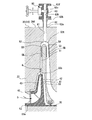
- a centrifugal compressor (rotary machine) 10 that is a rotary machine of the present embodiment mainly includes a casing 20 and a rotary shaft 30 that is rotatably supported around a central axis O in the casing 20. , And an impeller 40 that is attached to the rotating shaft 30 and compresses the process gas (fluid) G using centrifugal force.
- the casing 20 is provided with a plurality of ring members (diaphragms) 22 arranged in the direction of the central axis O of the rotary shaft 30. Further, the casing 20 is provided with an internal space 21 in which the diameter is reduced and the diameter is increased. An impeller 40 is accommodated in the internal space 21. When the impeller 40 is accommodated, a stationary component side flow path 50 is formed through which the process gas G flowing through the impeller 40 flows from the upstream side to the downstream side at a position between the impellers 40.
- the suction port 23 through which the process gas G flows from the outside into the stationary part side flow path 50 is provided at one end 20 a of the casing 20. Further, the other end portion 20 b of the casing 20 is provided with a discharge port 24 through which the process gas G flows out to the outside, following the stationary component side flow path 50.
- Support holes 25 and 26 for supporting both end portions of the rotating shaft 30 are formed on the one end portion 20a side and the other end portion 20b side of the casing 20, respectively.
- the rotary shaft 30 is supported by these support holes 25 and 26 via a journal bearing 27 so as to be rotatable around the central axis O.
- a thrust bearing 28 is further provided at one end 20 a of the casing 20, and the rotary shaft 30 is supported at one end 30 a so as to be rotatable in the direction of the central axis O via the thrust bearing 28.
- the plurality of impellers 40 are accommodated in the ring members 22 of the casing 20 with a space in the direction of the central axis O of the rotary shaft 30. 1 shows an example in which six impellers 40 are provided, it is sufficient that at least one impeller 40 is provided.
- the impeller 40 is a so-called closed impeller having a disk portion 41, a plurality of blade portions 42, and a cover portion 43, but may be an open impeller without the cover portion 43. Good.
- the stationary component side flow path 50 is formed of a diffuser part 51, a return bend part 52, and a return flow path part 53.
- the diffuser portion 51 is formed so as to extend from the outer peripheral side of the impeller 40 toward the outer peripheral side.
- the return bend portion 52 is formed continuously on the outer peripheral portion of the diffuser portion 51.
- the return bend portion 52 is formed so as to wrap around from the outer peripheral portion of the diffuser portion 51 to the other end portion 20b side of the casing 20 in a U shape in cross section and toward the inner peripheral side.
- the return flow path portion 53 is formed from the return bend portion 52 toward the inner peripheral side.
- an impeller-side channel 55 is formed in a space surrounded by the disk portion 41, the cover portion 43, and the blade portion 42 adjacent in the circumferential direction.
- the impeller side flow channel 55 has an end portion 55 a facing the one end portion 20 a side of the casing 20 facing the end portion of the return flow channel portion 53 of the stationary component side flow channel 50.
- the part 55 b is formed so as to face the outer peripheral side and to face the diffuser part 51 of the stationary component side flow path 50.
- the process gas G introduced into the stationary component side flow path 50 from the suction port 23 is in each of the impellers 40 that rotate around the central axis O together with the rotary shaft 30. It flows into the impeller side channel 55 from the end 55a close to the radially inner side.
- the process gas G that has flowed into the impeller side flow passage 55 flows out from the end portion 55b close to the radially outer side of the blade portion 42 toward the outer peripheral side. Then, the process gas G flows through the impeller side channel 55 toward the radially outer side, so that the process gas G is compressed.
- the process gas G flowing out from the impeller 40 at each stage flows to the outer peripheral side through the diffuser portion 51 of the stationary part side flow path 50, turns back in the flow direction at the return bend section 52, and passes through the return flow path section 53 to the rear impeller 40. Is sent to.
- the process gas G passes through the impeller side channel 55 and the stationary part side channel 50 of the impeller 40 provided in multiple stages from the one end 20a side to the other end 20b side of the casing 20. It is compressed in multiple stages and sent out from the discharge port 24.
- the centrifugal compressor 10 further includes a connection port 60 to which the borescope 100 can be connected.
- An insertion hole (communication hole) 61 is formed in the casing 20, and the connection port portion 60 includes a connection pipe 62 and an opening / closing valve 63 that can open and close the insertion hole 61.
- the insertion hole 61 is formed in the casing 20 so as to communicate the outer peripheral surface 20f of the casing 20 and the position facing the stationary component side flow path 50.
- the insertion hole 61 is formed to open to the outermost peripheral portion 52 t of the return bend portion 52 of the stationary component side flow path 50.
- the connecting pipe 62 has a cylindrical shape, and one end 62 a thereof is fixed to the outer peripheral surface 20 f of the casing 20 so as to communicate with the insertion hole 61.
- the on-off valve 63 is connected to the other end 62b of the connecting pipe 62 by a bolt (not shown) or the like.
- the on-off valve 63 includes a valve body 63 v that opens and closes a pipe line 63 h communicating with the connection pipe 62 and the insertion hole 61. Further, the opening / closing valve 63 is provided with a flange portion 63f whose diameter is increased on the outer peripheral side at the end opposite to the connection pipe 62 side.
- a borescope 100 and an oil injection device (not shown), which will be described later, can be detachably connected to the flange portion 63f.
- connection port portion 60 is provided in each return bend portion 52 located on the outer peripheral side of each stage of the impeller 40.
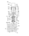
- the borescope (observation apparatus) 100 includes a fixed support portion 110 and a scope main body 120.
- the fixed support part 110 includes a flange member 111, a guide tube 112, a sleeve member (guide member) 113, and a support plate 114.
- the flange member 111 can be connected to the flange portion 63f of the connection port 60 by a bolt or the like.
- the guide tube 112 is tubular and has one end fixed to the flange member 111. The guide tube 112 communicates with the connection pipe 62 in a state where the flange member 111 is coupled to the flange portion 63 f of the connection port 60.
- the sleeve member 113 is tubular and is attached to the other end of the guide tube 112.
- An annular seal member 115 is provided on the inner peripheral surface of the sleeve member 113.
- the support plate 114 has a plate shape and is fixed to the sleeve member 113 so as to project to the outer peripheral side of the sleeve member 113.
- a plurality of guide holes are formed on the outer periphery of the support plate 114.
- the scope main body 120 includes a main body (main body) 121, a scope rod (insertion rod) 122, a support plate 123, a guide rod 124, and a spacer 125.
- the main body 121 includes an image sensor (not shown), a control unit (not shown), and the like, converts the captured image into an electrical signal, and outputs the signal to the outside.
- the scope rod 122 has a base end 122 a fixed to the main body 121.
- the scope rod 122 is inserted into the sleeve member 113 on the distal end 122b side.
- a sealing member 115 is interposed between the scope rod 122 and the sleeve member 113 to ensure sealing performance.
- An observation optical system such as an imaging lens (not shown) is provided at the distal end 122 b of the scope rod 122, and an image captured by the observation optical system is optically transmitted to the main body 121.
- the support plate 123 is plate-shaped and is integrally fixed to the outer peripheral surface of the scope rod 122 so as to project to the outer peripheral side of the scope rod 122.
- the guide rod 124 has a rod shape, and a plurality of guide rods 124 are provided on the outer peripheral portion of the support plate 123 at intervals in the circumferential direction.
- Each guide rod 124 is provided in parallel with the scope rod 122, and its base end portion 124 a is fixed integrally to the support plate 123.
- the guide rod 124 is inserted through the guide hole (not shown) formed in the support plate 114 on the fixed support portion 110 side on the distal end portion 124b side.
- a stopper member 126 (nut or the like) that protrudes to the outer peripheral side of the guide rod 124 is provided at the distal end portion 124 b of the guide rod 124.
- a plurality of spacers 125 are provided on the outer peripheral portion of the support plate 123 at intervals in the circumferential direction. Each spacer 125 is integrally fixed to the support plate 123 on the side facing the support plate 114.
- the spacer 125 is tubular, and a guide rod 124 is inserted through the spacer 125.
- the scope main body 120 can be brought into and out of contact with the fixed support portion 110 along the central axis direction of the scope rod 122. This is because the scope rod 122 is guided by the guide tube 112 and each guide rod 124 is guided by a guide hole (not shown) formed in the support plate 114 on the fixed support part 110 side. As shown in FIG. 4, the scope main body 120 is restricted from moving in the direction of approaching the support plate 114 when each spacer 125 abuts against the support plate 114. Further, as shown in FIG. 3, the amount of movement in the direction away from the support plate 114 is regulated by the stopper member 126 provided at the distal end portion 124 b of the guide rod 124.
- connection port 60 is attached to the casing 20 in advance.
- the centrifugal compressor 10 closes the on-off valve 63 of each connection port 60 during normal operation. Thereby, the process gas G does not leak out of the casing 20 from the stationary component side flow path 50 through the connection port portion 60.
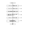
- the flange member 111 of the borescope 100 is coupled to the flange portion 63f of the connection port 60 by a bolt or the like (step S1).
- the borescope 100 is attached to the connection port 60.
- the on-off valve 63 is switched to the open state.
- the scope main body 120 is moved in a direction approaching the support plate 114 (the outer peripheral surface 20 f of the casing 20).
- the scope rod 122 is inserted into the pipe 63h, the connection pipe 62, and the insertion hole 61 of the on-off valve 63 of the connection port 60 while being guided by the guide rod 124 (step S2).
- the scope main body 120 is moved until each spacer 125 hits the support plate 114. Then, the distal end portion 122 b of the scope rod 122 is exposed from the outermost peripheral portion 52 t of the return bend portion 52 into the stationary component side flow path 50.
- the inside of the stationary part side flow path 50 is observed and imaged with an observation optical system (not shown) such as an imaging lens provided at the distal end portion 122b of the scope rod 122 (step S3).
- the captured image is converted into an electrical signal by the main body 121, output to an external monitor device, for example, and displayed as an image.
- the operator observes the inside of the output stationary part side channel 50 based on the displayed image, and confirms the state of adhesion / deposition of the solid matter SB (see FIG. 2) on the stationary part side channel 50. .
- the inside of the stationary component side flow path 50 can be visually inspected without disassembling the centrifugal compressor.
- the scope main body 120 After the inspection by the borescope 100, the scope main body 120 is moved away from the fixed support portion 110. Then, the scope rod 122 comes out of the pipe line 63 h of the on-off valve 63 of the connection port 60, the connection pipe 62, and the insertion hole 61. The scope main body 120 is moved until the movement of the support plate 114 is stopped by the stopper member 126 provided at the distal end portion 124b of the guide rod 124, and the on-off valve 63 of the connection port 60 is closed (step S4).
- the borescope 100 is detached from the connection port portion 60 by separating the flange member 111 from the flange portion 63f of the connection port portion 60 (step S5).
- the oil injection device (injection device: not shown).
- the oil injection device has an injection nozzle (not shown) inserted into the pipe 63h of the on-off valve 63, the connection pipe 62, and the insertion hole 61.
- this nozzle (not shown) is inserted into the pipe 63h, the connecting pipe 62, and the insertion hole 61 of the on-off valve 63, cleaning oil is injected from the tip of the nozzle (step S6).
- the solid matter SB in the stationary component side flow path 50 is removed by the jetted cleaning liquid oil.
- step S1 the step of connecting the scope main body 120 of the borescope 100 to the connection port 60 having the on-off valve 63 with the on-off valve 63 closed (step S1); Then, the opening / closing valve 63 is opened, the step of inserting the scope rod 122 of the borescope 100 into the insertion hole 61 (step S2), and the stationary component side flow path 50 by the observation optical system provided at the distal end portion of the scope rod 122.
- step S3 A step of observing the inside (step S3), a step of removing the scope rod 122 from the insertion hole 61 and closing the on-off valve 63 (step S4), and a step of removing the scope body 120 of the borescope 100 from the connection port 60 (step) S5) is executed.
- the borescope 100 can be inserted from the outside without disassembling the centrifugal compressor 10 and the inside of the stationary part side flow path 50 can be observed. Therefore, it is possible to easily confirm the state of adhesion / deposition of the solid substance SB on the gas flow path in the casing 20, thereby reducing maintenance labor and cost.
- the inspection can be performed even when the centrifugal compressor 10 is operated by attaching and detaching the borescope 100 with the on-off valve 63 provided in the connection port 60 closed. Therefore, the operation rate of the centrifugal compressor 10 can be improved.
- a seal member 115 that seals between the scope rod 122 and the sleeve member 113 is provided on the inner peripheral surface of the sleeve member 113. Accordingly, even when the borescope 100 is inserted into and removed from the connection port portion 60, the sealing property can be maintained and the process gas G in the casing 20 can be prevented from leaking to the outside.
- the cleaning liquid is supplied to the connection port 60.
- An oil injection device for spraying was connected, and the cleaning liquid was sprayed into the stationary component side flow path 50. Thereby, the cleaning liquid can be ejected at an appropriate timing to remove the solid matter SB.
- connection port 60 can be connected to an oil injection device including an injection nozzle that injects a cleaning liquid that removes the solid matter SB adhering to the stationary component side flow path 50.
- the connection port part 60 can be shared by the borescope 100 and the oil injection device.
- the borescope 100 is connected to the connection port 60 to inspect the adhesion state of the solid matter SB. Can do. That is, the above embodiment can be applied to the existing centrifugal compressor 10 at a low cost.
- connection port portion 60 is provided so that the insertion hole 61 faces the return bend portion 52 where the stationary component side flow path 50 is curved (or bent). If the distal end portion 122b of the scope rod 122 is disposed in the insertion hole 61 and the inside of the stationary component side flow path 50 is observed, the return bend portion 52 to which the solid matter SB easily adheres can be easily observed. Furthermore, the diffuser part 51 on one side of the return bend part 52 and the return flow path part 53 on the other side can be easily observed.
- the flow rate of the process gas G is low in the return bend portion 52. Loss on the flow can be suppressed.
- the present invention is not limited to the above-described embodiment, and the design can be changed without departing from the spirit of the present invention.
- the installation position of the connection port portion 60, the direction of the insertion hole 61, and the like may be any.
- the configurations of the borescope 100 and the connection port 60 shown in the above embodiment are merely examples, and configurations other than those described above may be used as long as they can exhibit a required function.
- connection port part 60 was set as the structure which combines the borescope 100 and an oil injection apparatus, the connection port part 60 for the borescope 100 and the connection port part for an oil injection apparatus are used. It may be provided separately.
- a water injection device is connected to the connection port 60 to which the borescope 100 is connected to reduce the temperature of the flow path by injecting water into the flow path in the casing 20 in order to suppress the generation of the solid matter SB. You may make it do.
- centrifugal compressor 10 is only described in the above embodiment, and can be changed as appropriate.
- the cleaning liquid can be sprayed at an appropriate timing to reduce maintenance work and costs, and improve the operating rate of the compression rate.
Landscapes
- Engineering & Computer Science (AREA)
- Mechanical Engineering (AREA)
- General Engineering & Computer Science (AREA)
- Physics & Mathematics (AREA)
- Health & Medical Sciences (AREA)
- Life Sciences & Earth Sciences (AREA)
- Chemical & Material Sciences (AREA)
- Analytical Chemistry (AREA)
- Biochemistry (AREA)
- General Health & Medical Sciences (AREA)
- General Physics & Mathematics (AREA)
- Immunology (AREA)
- Pathology (AREA)
- Structures Of Non-Positive Displacement Pumps (AREA)
- Control Of Positive-Displacement Air Blowers (AREA)
- Control Of Positive-Displacement Pumps (AREA)
Abstract
Description
本発明は、流路への固形物の付着・堆積状況を容易に確認して、メンテナンスの手間及びコストを抑えるとともに、圧縮率の稼働率を向上させることのできる回転機械の検査方法、回転機械を提供することを目的とする。
また、接続口部に設けた開閉弁を閉じた状態で、観察装置の着脱を行うことで、回転機械を運転した状態でも検査を行うことができる。
また、回転機械の運転中に挿入ロッドの先端部を流路内に挿入しても、流路が湾曲または屈曲している部分においては流体の流速も遅いため、流体の流れに与える損失を抑えることができる。
また、観察装置を接続口部に対して挿抜する際に、シール部材によってケーシング内の流体が外部に漏出するのを防ぐことができる。
ディフューザ部51は、インペラ40の外周側から、外周側に向けて延びるよう形成されている。
リターンベンド部52は、ディフューザ部51の外周部に連続して形成されている。リターンベンド部52は、ディフューザ部51の外周部からケーシング20の他端部20b側に、断面視U字状に回り込み、内周側に向かうように形成されている。
戻り流路部53は、リターンベンド部52から内周側に向けて形成されている。
フランジ部材111は、接続口部60のフランジ部63fに対し、ボルト等によって連結可能とされている。
ガイドチューブ112は、管状で、フランジ部材111に一端が固定されている。このガイドチューブ112は、フランジ部材111を接続口部60のフランジ部63fに連結した状態で、接続管62に連通する。
スコープロッド122の先端部122bには、撮像レンズ(図示無し)等の観察光学系が設けられ、観察光学系で撮像した画像は、光学的に本体部121に伝達される。
図4に示すように、スコープ本体120は、各スペーサ125がサポートプレート114に突き当たることで、サポートプレート114に接近する方向への移動量が規制される。また、図3に示すように、ガイドロッド124の先端部124bに設けられたストッパ部材126によって、サポートプレート114から離間する方向への移動量が規制される。
遠心圧縮機10は、通常運転中、各接続口部60の開閉弁63は閉状態とする。これにより、静止部品側流路50から接続口部60を通してプロセスガスGがケーシング20外に漏れることはない。
次いで、開閉弁63を開状態に切り換える。続いて、図4に示すように、スコープ本体120を、サポートプレート114(ケーシング20の外周面20f)に接近する方向に移動させる。すると、スコープロッド122が、ガイドロッド124にガイドされながら、接続口部60の開閉弁63の管路63h、接続管62、挿入孔61に挿入される(ステップS2)。各スペーサ125がサポートプレート114に突き当たるまでスコープ本体120を移動させる。すると、スコープロッド122の先端部122bが、リターンベンド部52の最外周部52tから静止部品側流路50内に露出する。
ここで、オイルインジェクション装置(図示無し)は、開閉弁63の管路63h、接続管62、挿入孔61に挿入されるインジェクションノズル(図示無し)を有している。このノズル(図示無し)を、開閉弁63の管路63h、接続管62、挿入孔61に挿入した状態で、ノズルの先端部から洗浄液用オイルを噴射する(ステップS6)。噴射された洗浄液用オイルにより、静止部品側流路50内の固形物SBが除去される。
これにより、適切なタイミングで洗浄液を噴射して固形物SBの除去を行うことができる。
また、既設の遠心圧縮機10に、オイルインジェクション装置接続用の接続口部60が設けられていれば、その接続口部60にボアスコープ100を接続して固形物SBの付着状況を検査することができる。すなわち、既設の遠心圧縮機10に対しても、上記実施形態を低コストで適用することができる。
なお、本発明は、上述した実施形態に限定されるものではなく、本発明の趣旨を逸脱しない範囲において、設計変更可能である。
例えば、ボアスコープ100を装着できるのであれば、接続口部60の設置位置、挿入孔61の方向等は、いかなるようにしてもよい。
また、上記実施形態で示したボアスコープ100や接続口部60の構成は一例に過ぎず、所要の機能を発揮することができるのであれば、上記に示した以外の構成としてもよい。
20 ケーシング
20a 一端部
20b 他端部
20f 外周面
21 内部空間
22 リング部材
23 吸込口
24 排出口
25,26 支持孔
27 ジャーナル軸受
28 スラスト軸受
30 回転軸
30a 一端側
40 インペラ
41 ディスク部
42 ブレード部
43 カバー部
50 静止部品側流路(流路)
51 ディフューザ部
52 リターンベンド部
52t 最外周部
53 戻り流路部
55 インペラ側流路
55a 端部
55b 端部
60 接続口部
61 挿入孔(連通孔)
62 接続管
62a 一端
62b 他端
63 開閉弁
63f フランジ部
63h 管路
63v 弁体
100 ボアスコープ(観察装置)
110 固定サポート部
111 フランジ部材
112 ガイドチューブ
113 スリーブ部材(ガイド部材)
114 サポートプレート
115 シール部材
120 スコープ本体
121 本体部(本体)
122 スコープロッド(挿入ロッド)
122a 基端部
122b 先端部
123 サポートプレート
124 ガイドロッド
124a 基端部
124b 先端部
125 スペーサ
126 ストッパ部材
G プロセスガス(流体)
O 中心軸
SB 固形物
Claims (5)
- 流体が流れる流路を有した回転機械の検査方法であって、
回転機械の外部と前記流路とを連通する連通孔を開閉する開閉弁を有した接続口部に、前記開閉弁を閉じた状態で観察装置の本体を接続する工程と、
前記開閉弁を開き、前記連通孔内に、前記観察装置の前記本体から突出する挿入ロッドを挿入する工程と、
前記挿入ロッドの先端部に設けられた観察光学系により前記流路内を観察する工程と、
前記挿入ロッドを前記連通孔から抜き、前記開閉弁を閉じる工程と、
前記観察装置の前記本体を前記接続口部から取り外す工程と、
を含む回転機械の検査方法。 - 前記観察装置で得た前記流路内の観察画像に基づき、前記流路内から固形物を除去すべきと判断される場合に、前記接続口部に洗浄液を噴射するインジェクションノズルを備えたインジェクション装置を接続し、前記流路内に前記洗浄液を噴射する工程をさらに含む請求項1に記載の回転機械の検査方法。
- 前記接続口部は、前記流路が湾曲または屈曲している部分に臨むよう設けられている、請求項1又は2に記載の回転機械の検査方法。
- 流体が流れる流路、及び該流路と外部とを連通する連通孔が形成されたケーシングと、
ケーシングの外部に設けられ、前記連通孔を開閉する開閉弁と、
前記開閉弁に対して前記ケーシングから離間する側に接続され、内部に観察装置の挿入ロッドが挿入される管状のガイド部材と、
前記ガイド部材の内周面に設けられ、前記ガイド部材と前記挿入ロッドとの間をシールするシール部材と、
を備える回転機械。 - 前記開閉弁に、前記流路内に付着した固形物を除去する洗浄液を噴射するインジェクションノズルを備えたインジェクション装置が接続可能である請求項4に記載の回転機械。
Priority Applications (3)
| Application Number | Priority Date | Filing Date | Title |
|---|---|---|---|
| US15/561,913 US10684234B2 (en) | 2015-03-31 | 2015-03-31 | Method for inspecting rotary machine, and rotary machine |
| PCT/JP2015/060203 WO2016157434A1 (ja) | 2015-03-31 | 2015-03-31 | 回転機械の検査方法、回転機械 |
| JP2017508943A JPWO2016157434A1 (ja) | 2015-03-31 | 2015-03-31 | 回転機械の検査方法、回転機械 |
Applications Claiming Priority (1)
| Application Number | Priority Date | Filing Date | Title |
|---|---|---|---|
| PCT/JP2015/060203 WO2016157434A1 (ja) | 2015-03-31 | 2015-03-31 | 回転機械の検査方法、回転機械 |
Publications (1)
| Publication Number | Publication Date |
|---|---|
| WO2016157434A1 true WO2016157434A1 (ja) | 2016-10-06 |
Family
ID=57006642
Family Applications (1)
| Application Number | Title | Priority Date | Filing Date |
|---|---|---|---|
| PCT/JP2015/060203 Ceased WO2016157434A1 (ja) | 2015-03-31 | 2015-03-31 | 回転機械の検査方法、回転機械 |
Country Status (3)
| Country | Link |
|---|---|
| US (1) | US10684234B2 (ja) |
| JP (1) | JPWO2016157434A1 (ja) |
| WO (1) | WO2016157434A1 (ja) |
Cited By (2)
| Publication number | Priority date | Publication date | Assignee | Title |
|---|---|---|---|---|
| EP3505767A1 (en) * | 2017-12-27 | 2019-07-03 | Mitsubishi Heavy Industries Compressor Corporation | Centrifugal compressor and method of modifying centrifugal compressor |
| CN119664807A (zh) * | 2025-02-20 | 2025-03-21 | 成都中科翼能科技有限公司 | 一种压气机试验设备的轴向力卸载结构 |
Families Citing this family (4)
| Publication number | Priority date | Publication date | Assignee | Title |
|---|---|---|---|---|
| US11536277B2 (en) | 2020-04-30 | 2022-12-27 | Trane International Inc. | Interstage capacity control valve with side stream flow distribution and flow regulation for multi-stage centrifugal compressors |
| US11391289B2 (en) | 2020-04-30 | 2022-07-19 | Trane International Inc. | Interstage capacity control valve with side stream flow distribution and flow regulation for multi-stage centrifugal compressors |
| US11421709B2 (en) | 2020-09-08 | 2022-08-23 | Honeywell International Inc. | Systems for interstage particle separation in multistage radial compressors of turbine engines |
| US11841026B2 (en) | 2021-11-03 | 2023-12-12 | Trane International Inc. | Compressor interstage throttle, and method of operating therof |
Citations (13)
| Publication number | Priority date | Publication date | Assignee | Title |
|---|---|---|---|---|
| JPS56104191A (en) * | 1980-01-21 | 1981-08-19 | Hitachi Ltd | Deposit monitoring device for turbo machine |
| JPH04134961U (ja) * | 1991-06-04 | 1992-12-15 | 三菱重工業株式会社 | 軸封装置におけるカーボンパツキン摩耗量測定器 |
| JPH05312167A (ja) * | 1992-05-11 | 1993-11-22 | Mitsubishi Heavy Ind Ltd | 密閉型ロータリ圧縮機 |
| JPH078590U (ja) * | 1993-07-05 | 1995-02-07 | セイコー精機株式会社 | ターボ分子ポンプ |
| JPH09317673A (ja) * | 1996-05-29 | 1997-12-09 | Mitsubishi Electric Corp | 圧縮機 |
| JP2001317495A (ja) * | 2000-03-29 | 2001-11-16 | Watson Cogeneration Co | 多段ガスコンプレッサ及び多段ガスコンプレッサの能力を増大させる方法 |
| JP2002070741A (ja) * | 2000-08-28 | 2002-03-08 | Fujine Sangyo:Kk | 空調機等の圧縮機用液面検知装置 |
| JP2004117091A (ja) * | 2002-09-25 | 2004-04-15 | Boc Edwards Technologies Ltd | 真空ポンプ |
| JP2008151030A (ja) * | 2006-12-18 | 2008-07-03 | Mitsubishi Heavy Ind Ltd | 圧縮機の洗浄装置及び洗浄方法 |
| JP2008248754A (ja) * | 2007-03-29 | 2008-10-16 | Tokyo Electron Ltd | ターボ分子ポンプ、基板処理装置、及びターボ分子ポンプの堆積物付着抑制方法 |
| US20090133718A1 (en) * | 2006-09-20 | 2009-05-28 | Borg Warner Inc. | Automatic compressor stage cleaning for air boost systems |
| JP2010127245A (ja) * | 2008-11-28 | 2010-06-10 | Mitsubishi Heavy Ind Ltd | 遠心圧縮機 |
| JP2012219718A (ja) * | 2011-04-08 | 2012-11-12 | Kawamoto Pump Mfg Co Ltd | ブラケット及び水中ポンプ |
Family Cites Families (14)
| Publication number | Priority date | Publication date | Assignee | Title |
|---|---|---|---|---|
| JPS5419370B2 (ja) | 1973-06-12 | 1979-07-14 | ||
| GB2036363A (en) * | 1978-12-04 | 1980-06-25 | United Technologies Corp | Inspecting Stator Vanes |
| JPS58174918A (ja) * | 1982-04-07 | 1983-10-14 | Mitsubishi Heavy Ind Ltd | 容器内部の目視検査装置 |
| US4713120A (en) * | 1986-02-13 | 1987-12-15 | United Technologies Corporation | Method for cleaning a gas turbine engine |
| US20060038988A1 (en) | 2004-08-20 | 2006-02-23 | General Electric Company | Borescope assembly for detecting a condition of a rotating part |
| EP1681128A1 (de) * | 2005-01-14 | 2006-07-19 | Siemens Aktiengesellschaft | Verfahren zur Herstellung eines Lochs und Vorrichtung |
| US7458768B2 (en) | 2005-06-28 | 2008-12-02 | United Technologies Corporation | Borescope inspection port device for gas turbine engine and gas turbine engine using same |
| JP5461143B2 (ja) | 2009-10-23 | 2014-04-02 | 三菱重工業株式会社 | 遠心圧縮機 |
| JP2011111990A (ja) | 2009-11-27 | 2011-06-09 | Mitsubishi Heavy Ind Ltd | 遠心圧縮機 |
| JP5675121B2 (ja) | 2010-01-27 | 2015-02-25 | 三菱重工業株式会社 | 遠心圧縮機、および洗浄方法 |
| US9765649B2 (en) | 2013-05-08 | 2017-09-19 | United Technologies Corporation | Borescope inspection port fitting |
| JP5575308B2 (ja) | 2013-07-08 | 2014-08-20 | 三菱重工業株式会社 | 遠心圧縮機 |
| JP5869044B2 (ja) | 2014-05-15 | 2016-02-24 | 三菱重工業株式会社 | 遠心圧縮機 |
| US9810098B2 (en) * | 2014-07-11 | 2017-11-07 | General Electric Company | System and method for inspecting turbomachines |
-
2015
- 2015-03-31 WO PCT/JP2015/060203 patent/WO2016157434A1/ja not_active Ceased
- 2015-03-31 JP JP2017508943A patent/JPWO2016157434A1/ja not_active Ceased
- 2015-03-31 US US15/561,913 patent/US10684234B2/en active Active
Patent Citations (13)
| Publication number | Priority date | Publication date | Assignee | Title |
|---|---|---|---|---|
| JPS56104191A (en) * | 1980-01-21 | 1981-08-19 | Hitachi Ltd | Deposit monitoring device for turbo machine |
| JPH04134961U (ja) * | 1991-06-04 | 1992-12-15 | 三菱重工業株式会社 | 軸封装置におけるカーボンパツキン摩耗量測定器 |
| JPH05312167A (ja) * | 1992-05-11 | 1993-11-22 | Mitsubishi Heavy Ind Ltd | 密閉型ロータリ圧縮機 |
| JPH078590U (ja) * | 1993-07-05 | 1995-02-07 | セイコー精機株式会社 | ターボ分子ポンプ |
| JPH09317673A (ja) * | 1996-05-29 | 1997-12-09 | Mitsubishi Electric Corp | 圧縮機 |
| JP2001317495A (ja) * | 2000-03-29 | 2001-11-16 | Watson Cogeneration Co | 多段ガスコンプレッサ及び多段ガスコンプレッサの能力を増大させる方法 |
| JP2002070741A (ja) * | 2000-08-28 | 2002-03-08 | Fujine Sangyo:Kk | 空調機等の圧縮機用液面検知装置 |
| JP2004117091A (ja) * | 2002-09-25 | 2004-04-15 | Boc Edwards Technologies Ltd | 真空ポンプ |
| US20090133718A1 (en) * | 2006-09-20 | 2009-05-28 | Borg Warner Inc. | Automatic compressor stage cleaning for air boost systems |
| JP2008151030A (ja) * | 2006-12-18 | 2008-07-03 | Mitsubishi Heavy Ind Ltd | 圧縮機の洗浄装置及び洗浄方法 |
| JP2008248754A (ja) * | 2007-03-29 | 2008-10-16 | Tokyo Electron Ltd | ターボ分子ポンプ、基板処理装置、及びターボ分子ポンプの堆積物付着抑制方法 |
| JP2010127245A (ja) * | 2008-11-28 | 2010-06-10 | Mitsubishi Heavy Ind Ltd | 遠心圧縮機 |
| JP2012219718A (ja) * | 2011-04-08 | 2012-11-12 | Kawamoto Pump Mfg Co Ltd | ブラケット及び水中ポンプ |
Cited By (3)
| Publication number | Priority date | Publication date | Assignee | Title |
|---|---|---|---|---|
| EP3505767A1 (en) * | 2017-12-27 | 2019-07-03 | Mitsubishi Heavy Industries Compressor Corporation | Centrifugal compressor and method of modifying centrifugal compressor |
| JP2019116854A (ja) * | 2017-12-27 | 2019-07-18 | 三菱重工コンプレッサ株式会社 | 遠心圧縮機および遠心圧縮機の改造方法 |
| CN119664807A (zh) * | 2025-02-20 | 2025-03-21 | 成都中科翼能科技有限公司 | 一种压气机试验设备的轴向力卸载结构 |
Also Published As
| Publication number | Publication date |
|---|---|
| US10684234B2 (en) | 2020-06-16 |
| JPWO2016157434A1 (ja) | 2018-01-25 |
| US20180119569A1 (en) | 2018-05-03 |
Similar Documents
| Publication | Publication Date | Title |
|---|---|---|
| JPWO2016157434A1 (ja) | 回転機械の検査方法、回転機械 | |
| CN107013500B (zh) | 用于燃气涡轮发动机的内部构件的原地清洁的系统和方法 | |
| JP5132591B2 (ja) | 点検ポートプラグ装置 | |
| US20160305286A1 (en) | Shroud assembly and shroud for gas turbine engine | |
| RU2589417C2 (ru) | Система уплотнения вала | |
| RU2682301C2 (ru) | Элемент газотурбинного двигателя, содержащий вспомогательное уплотнительное средство, и способ тестирования этого элемента | |
| CN109752141B (zh) | 一种机械密封产品检测加工装置及方法 | |
| ITMI20102466A1 (it) | Sistema compressore motore e metodo | |
| US9267393B2 (en) | Dry ice cleaning apparatus for gas turbine compressor | |
| KR101321457B1 (ko) | 유체이송용 커플링 장치의 플러그 | |
| WO2018147013A1 (ja) | 蒸気タービン | |
| KR20080081903A (ko) | 유체이송용 커플링 장치의 소켓 | |
| CN110337531B (zh) | 涡轮机壳体和用于组装具有涡轮机壳体的涡轮机的方法 | |
| US20180017073A1 (en) | Centrifugal compressor casing and centrifugal compressor | |
| KR101173266B1 (ko) | 인라인 펌프 | |
| EP3450702A1 (en) | Fluid communication between a stationary structure and a rotating structure | |
| JP7358660B2 (ja) | 締め付けボルト内に流動ループを有するコンプレッサ用ロータ | |
| US20160238480A1 (en) | Seal vacuum check tool | |
| JP5909061B2 (ja) | 往復圧縮機クランクシャフトアダプタ及び方法 | |
| US20130312861A1 (en) | Self-sealing tube for a gas turbine secondary air system | |
| US12055152B1 (en) | In a turbomachine, rotor structure with seal assembly and method in connection with same | |
| US11092164B2 (en) | Non-welded suction chamber for surface pumping systems | |
| CN113607889B (zh) | 一种可在线检修的流体测量装置 | |
| KR102369681B1 (ko) | 정수라인의 튜브 압입 피팅구조 | |
| JP6152527B2 (ja) | 粒子分離デバイスおよび流量調節デバイスの連結を用いた方法ならびに機械装置 |
Legal Events
| Date | Code | Title | Description |
|---|---|---|---|
| 121 | Ep: the epo has been informed by wipo that ep was designated in this application |
Ref document number: 15887587 Country of ref document: EP Kind code of ref document: A1 |
|
| ENP | Entry into the national phase |
Ref document number: 2017508943 Country of ref document: JP Kind code of ref document: A |
|
| WWE | Wipo information: entry into national phase |
Ref document number: 15561913 Country of ref document: US |
|
| NENP | Non-entry into the national phase |
Ref country code: DE |
|
| 122 | Ep: pct application non-entry in european phase |
Ref document number: 15887587 Country of ref document: EP Kind code of ref document: A1 |