WO2016157425A1 - 回転機械の検査方法、回転機械 - Google Patents
回転機械の検査方法、回転機械 Download PDFInfo
- Publication number
- WO2016157425A1 WO2016157425A1 PCT/JP2015/060177 JP2015060177W WO2016157425A1 WO 2016157425 A1 WO2016157425 A1 WO 2016157425A1 JP 2015060177 W JP2015060177 W JP 2015060177W WO 2016157425 A1 WO2016157425 A1 WO 2016157425A1
- Authority
- WO
- WIPO (PCT)
- Prior art keywords
- flow path
- width
- solid matter
- sensor
- rotating machine
- Prior art date
- Legal status (The legal status is an assumption and is not a legal conclusion. Google has not performed a legal analysis and makes no representation as to the accuracy of the status listed.)
- Ceased
Links
Images




Classifications
-
- F—MECHANICAL ENGINEERING; LIGHTING; HEATING; WEAPONS; BLASTING
- F04—POSITIVE - DISPLACEMENT MACHINES FOR LIQUIDS; PUMPS FOR LIQUIDS OR ELASTIC FLUIDS
- F04D—NON-POSITIVE-DISPLACEMENT PUMPS
- F04D27/00—Control, e.g. regulation, of pumps, pumping installations or pumping systems specially adapted for elastic fluids
- F04D27/001—Testing thereof; Determination or simulation of flow characteristics; Stall or surge detection, e.g. condition monitoring
-
- B—PERFORMING OPERATIONS; TRANSPORTING
- B08—CLEANING
- B08B—CLEANING IN GENERAL; PREVENTION OF FOULING IN GENERAL
- B08B9/00—Cleaning hollow articles by methods or apparatus specially adapted thereto
- B08B9/02—Cleaning pipes or tubes or systems of pipes or tubes
- B08B9/027—Cleaning the internal surfaces; Removal of blockages
-
- F—MECHANICAL ENGINEERING; LIGHTING; HEATING; WEAPONS; BLASTING
- F04—POSITIVE - DISPLACEMENT MACHINES FOR LIQUIDS; PUMPS FOR LIQUIDS OR ELASTIC FLUIDS
- F04B—POSITIVE-DISPLACEMENT MACHINES FOR LIQUIDS; PUMPS
- F04B51/00—Testing machines, pumps, or pumping installations
-
- F—MECHANICAL ENGINEERING; LIGHTING; HEATING; WEAPONS; BLASTING
- F04—POSITIVE - DISPLACEMENT MACHINES FOR LIQUIDS; PUMPS FOR LIQUIDS OR ELASTIC FLUIDS
- F04D—NON-POSITIVE-DISPLACEMENT PUMPS
- F04D17/00—Radial-flow pumps, e.g. centrifugal pumps; Helico-centrifugal pumps
- F04D17/08—Centrifugal pumps
- F04D17/10—Centrifugal pumps for compressing or evacuating
- F04D17/12—Multi-stage pumps
- F04D17/122—Multi-stage pumps the individual rotor discs being, one for each stage, on a common shaft and axially spaced, e.g. conventional centrifugal multi- stage compressors
-
- F—MECHANICAL ENGINEERING; LIGHTING; HEATING; WEAPONS; BLASTING
- F04—POSITIVE - DISPLACEMENT MACHINES FOR LIQUIDS; PUMPS FOR LIQUIDS OR ELASTIC FLUIDS
- F04D—NON-POSITIVE-DISPLACEMENT PUMPS
- F04D29/00—Details, component parts, or accessories
- F04D29/70—Suction grids; Strainers; Dust separation; Cleaning
-
- F—MECHANICAL ENGINEERING; LIGHTING; HEATING; WEAPONS; BLASTING
- F04—POSITIVE - DISPLACEMENT MACHINES FOR LIQUIDS; PUMPS FOR LIQUIDS OR ELASTIC FLUIDS
- F04D—NON-POSITIVE-DISPLACEMENT PUMPS
- F04D29/00—Details, component parts, or accessories
- F04D29/70—Suction grids; Strainers; Dust separation; Cleaning
- F04D29/701—Suction grids; Strainers; Dust separation; Cleaning especially adapted for elastic fluid pumps
-
- F—MECHANICAL ENGINEERING; LIGHTING; HEATING; WEAPONS; BLASTING
- F04—POSITIVE - DISPLACEMENT MACHINES FOR LIQUIDS; PUMPS FOR LIQUIDS OR ELASTIC FLUIDS
- F04D—NON-POSITIVE-DISPLACEMENT PUMPS
- F04D29/00—Details, component parts, or accessories
- F04D29/70—Suction grids; Strainers; Dust separation; Cleaning
- F04D29/701—Suction grids; Strainers; Dust separation; Cleaning especially adapted for elastic fluid pumps
- F04D29/705—Adding liquids
-
- B—PERFORMING OPERATIONS; TRANSPORTING
- B08—CLEANING
- B08B—CLEANING IN GENERAL; PREVENTION OF FOULING IN GENERAL
- B08B2209/00—Details of machines or methods for cleaning hollow articles
- B08B2209/02—Details of apparatuses or methods for cleaning pipes or tubes
- B08B2209/027—Details of apparatuses or methods for cleaning pipes or tubes for cleaning the internal surfaces
-
- F—MECHANICAL ENGINEERING; LIGHTING; HEATING; WEAPONS; BLASTING
- F04—POSITIVE - DISPLACEMENT MACHINES FOR LIQUIDS; PUMPS FOR LIQUIDS OR ELASTIC FLUIDS
- F04D—NON-POSITIVE-DISPLACEMENT PUMPS
- F04D29/00—Details, component parts, or accessories
- F04D29/08—Sealings
-
- F—MECHANICAL ENGINEERING; LIGHTING; HEATING; WEAPONS; BLASTING
- F05—INDEXING SCHEMES RELATING TO ENGINES OR PUMPS IN VARIOUS SUBCLASSES OF CLASSES F01-F04
- F05D—INDEXING SCHEME FOR ASPECTS RELATING TO NON-POSITIVE-DISPLACEMENT MACHINES OR ENGINES, GAS-TURBINES OR JET-PROPULSION PLANTS
- F05D2260/00—Function
- F05D2260/60—Fluid transfer
- F05D2260/607—Preventing clogging or obstruction of flow paths by dirt, dust, or foreign particles
Definitions
- the present invention relates to a rotating machine inspection method and a rotating machine.
- centrifugal compressors are used to pump process gas.
- a component in the gas may react to generate a polymer-like or coke-like solid in the flow path.
- the production of solid matter may be affected by an increase in the temperature of the process gas in the compression step.
- Patent Document 1 discloses a configuration in which a spray-type nozzle is installed and atomized cleaning liquid is injected into the flow path in order to remove solid matter that adheres and accumulates in the flow path of the centrifugal compressor. Has been.
- the present invention relates to a rotating machine inspection method and a rotating machine capable of easily confirming the state of solid matter adhesion / deposition on a flow path, reducing maintenance labor and cost, and improving the operating rate of the compression ratio. The purpose is to provide.
- the rotating machine inspection method is a rotating machine inspection method having a flow path through which a fluid flows, and is provided at a position facing the flow path in a stationary part of the rotating machine. And a step of measuring the width of the flow path by a non-contact sensor and a step of determining whether or not the measured width of the flow path is less than a predetermined lower limit threshold value.
- the solid matter can be adhered to the flow path without disassembling the rotating machine. Deposition status can be confirmed. Specifically, if solid matter adheres to the channel wall surface, the channel width becomes narrower. Therefore, if the measured channel width is less than the predetermined lower limit threshold, it can be easily determined that a certain amount of solid matter has adhered to the channel.
- the cleaning liquid is injected into the flow path when the measured width of the flow path is less than a predetermined lower threshold. And a step of removing the solid matter adhering to the flow path.
- the solid matter when solid matter adheres to the flow path at a certain level or more, the solid matter can be removed at an appropriate timing by ejecting the cleaning liquid to remove the solid matter.
- the width of the flow path is measured by the non-contact sensor while performing the step of removing the solid matter.
- the step of removing the solid matter may be terminated.
- the attached solid matter is removed, thereby widening the channel width.
- the flow path width is equal to or greater than the upper limit threshold value and the attached solid matter is removed beyond a predetermined reference, the removal of the solid matter can be completed. Thereby, the usage-amount of a washing
- cleaning liquid can be suppressed and the removal process of a solid substance can be performed efficiently.
- the rotating machine is provided at a position facing the flow path in the casing in which the flow path for fluid flows is formed and the stationary part of the casing, and measures the width of the flow path. And a non-contact sensor.
- the flow path width of the flow path can be detected by the non-contact sensor even when the rotary machine is operated. As a result, it is possible to confirm the state of solid matter adhesion / deposition on the flow path without disassembling the rotating machine.
- the rotary machine is measured by the injection device including a nozzle for injecting a cleaning liquid for removing the solid matter attached to the flow path, and the non-contact sensor. And a controller that controls the operation of the injection device in accordance with the width of the flow path.
- the injection device can be operated to automatically remove the solid matter. Moreover, the removal process can be automatically stopped at the stage where the attached solid matter has been removed.
- a centrifugal compressor (rotary machine) 10 that is a rotary machine of the present embodiment mainly includes a casing 20 and a rotary shaft 30 that is rotatably supported around a central axis O in the casing 20. , And an impeller 40 that is attached to the rotating shaft 30 and compresses the process gas (fluid) G using centrifugal force.
- the casing 20 is provided with a plurality of ring members (diaphragms) 22 arranged in the direction of the central axis O of the rotary shaft 30. Further, the casing 20 is provided with an internal space 21 in which the diameter is reduced and the diameter is increased. An impeller 40 is accommodated in the internal space 21. When the impeller 40 is accommodated, a stationary component side flow path (flow path) 50 is formed to flow the process gas (fluid) G flowing through the impeller 40 from the upstream side to the downstream side at a position between the impellers 40. ing.
- the suction port 23 through which the process gas G flows from the outside into the stationary part side flow path 50 is provided at one end 20 a of the casing 20. Further, the other end portion 20 b of the casing 20 is provided with a discharge port 24 through which the process gas G flows out to the outside, following the stationary component side flow path 50.
- Support holes 25 and 26 for supporting both end portions of the rotating shaft 30 are formed on the one end portion 20a side and the other end portion 20b side of the casing 20, respectively.
- the rotary shaft 30 is supported by these support holes 25 and 26 via a journal bearing 27 so as to be rotatable around the central axis O.
- a thrust bearing 28 is further provided at one end 20 a of the casing 20, and the rotary shaft 30 is supported at one end 30 a so as to be rotatable in the direction of the central axis O via the thrust bearing 28.
- the plurality of impellers 40 are accommodated in the ring members 22 of the casing 20 with a space in the direction of the central axis O of the rotary shaft 30. 1 shows an example in which six impellers 40 are provided, it is sufficient that at least one impeller 40 is provided.
- the impeller 40 is a so-called closed impeller having a disk portion 41, a plurality of blade portions 42, and a cover portion 43, but may be an open impeller without the cover portion 43. Good.
- the stationary component side flow path 50 is formed of a diffuser part 51, a return bend part 52, and a return flow path part 53.
- the diffuser portion 51 is formed so as to extend from the outer peripheral side of the impeller 40 toward the outer peripheral side.
- the return bend portion 52 is formed continuously on the outer peripheral portion of the diffuser portion 51.
- the return bend portion 52 is formed from the outer peripheral portion of the diffuser portion 51 to the other end portion 20b side of the casing 20 in a U shape in sectional view and toward the inner peripheral side.
- the return flow path portion 53 is formed from the return bend portion 52 toward the inner peripheral side.
- an impeller-side channel 55 is formed in a space surrounded by the disk portion 41, the cover portion 43, and the blade portion 42 adjacent in the circumferential direction.
- the impeller side flow channel 55 has an end portion 55 a facing the one end portion 20 a side of the casing 20 facing the end portion of the return flow channel portion 53 of the stationary component side flow channel 50.
- the part 55 b is formed so as to face the outer peripheral side and to face the diffuser part 51 of the stationary component side flow path 50.
- the process gas G introduced into the stationary component side flow path 50 from the suction port 23 is in each of the impellers 40 that rotate around the central axis O together with the rotary shaft 30. It flows into the impeller side channel 55 from the end 55a close to the radially inner side.
- the process gas G that has flowed into the impeller side flow passage 55 flows out from the end portion 55b close to the radially outer side of the blade portion 42 toward the outer peripheral side. Then, the process gas G flows through the impeller side channel 55 toward the radially outer side, so that the process gas G is compressed.
- the process gas G flowing out from the impeller 40 at each stage flows to the outer peripheral side through the diffuser portion 51 of the stationary part side flow path 50, turns back in the flow direction at the return bend section 52, and passes through the return flow path section 53 to the rear impeller 40. Is sent to.
- the process gas G passes through the impeller side channel 55 and the stationary part side channel 50 of the impeller 40 provided in multiple stages from the one end 20a side to the other end 20b side of the casing 20. It is compressed in multiple stages and sent out from the discharge port 24.
- the centrifugal compressor 10 is provided with a sensor 60 at a position facing the stationary component side flow path 50 in the casing 20.
- the sensor 60 detects the thickness of the solid material SB (see FIG. 2) adhering to the inner peripheral surface of the stationary component-side flow path 50, and thus crosses the width of the stationary component-side flow path 50 (the flow direction of the process gas G). Measure the width in the direction to do.
- a sensor 60 is a non-contact sensor and preferably emits infrared light or laser light as measurement light B.
- the sensor 60 is installed on one side (the suction port 23 side in the direction of the central axis O) of the stationary component side flow path 50.
- the sensor 60 irradiates the measurement light B made of infrared light or laser light from the direction orthogonal to the other inner peripheral surface 50f of the stationary component side flow path 50, and receives reflected light.
- the sensor 60 detects the channel width of the stationary component side channel 50. That is, in the sensor 60, if the solid material SB is not attached to the inner peripheral surface 50f of the stationary component side flow channel 50, the distance from the sensor 60 to the inner peripheral surface 50f is measured as the flow channel width. Moreover, in the sensor 60, if solid substance SB has adhered to the internal peripheral surface 50f of the stationary component side flow path 50, the distance to the surface of the solid substance SB is measured as a flow path width.
- Such a sensor 60 is provided in a stationary part of the centrifugal compressor 10 that does not rotate integrally with the rotary shaft 30.
- the sensor 60 is provided at a position facing the diffuser portion 51 located on the outer peripheral side of each stage of the impeller 40.
- the sensor 60 is preferably provided at a position facing the position where the solid matter SB easily adheres with the stationary component side flow path 50 interposed therebetween.
- the senor 60 transmits the measurement result by irradiation of the measurement light B to the measurement apparatus main body 80 provided outside the centrifugal compressor 10 by wireless or wired.
- the sensor 60 is connected to the measurement device main body 80 by wire, it is necessary to provide a seal member so as to maintain a sealing property in a portion where the signal line connected to the sensor 60 penetrates the casing 20 of the centrifugal compressor 10.
- the sensor 60 is wirelessly connected to the measurement apparatus main body 80, such a configuration is not necessary.
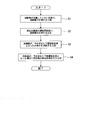
- the solid matter SB is not attached to the inner peripheral surface 50f of the stationary component side flow path 50 before or immediately after the centrifugal compressor 10 is installed. Then, the channel width of the stationary component side channel 50 is measured (step S1).
- the channel width of the stationary component side channel 50 is measured by the sensor 60 at an appropriate timing (step S2).
- the measurement of the channel width by the sensor 60 may be performed periodically at a predetermined interval, or may be constantly performed at every minute time interval during operation of the centrifugal compressor 10.
- step S3 it is determined whether or not the flow path width measured by the sensor 60 is less than a predetermined lower threshold.
- the solid matter SB having a thickness equal to or larger than the reference value is attached to the inner peripheral surface 50f of the stationary component side flow path 50 in advance. Therefore, when the flow path width measured by the sensor 60 is less than the predetermined lower limit threshold, it is determined that the solid matter SB is attached to the inner peripheral surface 50f of the stationary component side flow passage 50, and the solid matter SB is determined. Is removed (step S4).
- an oil injection device (not shown) that injects cleaning oil or the like as a cleaning liquid is used, and a technique such as injecting the cleaning liquid onto the inner peripheral surface 50f of the stationary component side flow path 50 is exemplified. .
- the measurement apparatus main body 80 needs to remove the solid matter SB by sound, blinking of a lamp, display of a message, or the like. An alarm signal indicating this may be output to the outside.
- the sensor 60 for detecting the flow width of the stationary component side flow path 50 formed in the casing 20 of the centrifugal compressor 10 is provided. I prepared. Accordingly, it is possible to check the adhesion / deposition state of the solid matter SB to the stationary component side flow path 50 without disassembling the centrifugal compressor 10, and it is possible to reduce maintenance effort and cost.
- such a sensor 60 can detect the flow path width of the stationary part side flow path 50 even when the centrifugal compressor 10 is operated. Therefore, the operation rate of the centrifugal compressor 10 can be improved.
- the oil injection device uses the stationary component
- the cleaning liquid was sprayed into the side channel 50 to remove the solid matter SB.
- the cleaning liquid can be ejected at an appropriate timing to remove the solid matter SB.
- the senor 60 may be installed on the other side of the stationary component side flow path 50 (on the outlet 24 side in the direction of the central axis O).
- the centrifugal compressor 10 shown in the second embodiment includes an oil injection device (injection device) 70, and a measuring device main body 80 having a control unit 80a and a determination unit 80b in addition to the sensor 60 shown in the first embodiment.
- injection device injection device
- measuring device main body 80 having a control unit 80a and a determination unit 80b in addition to the sensor 60 shown in the first embodiment.
- a position facing the stationary component side flow path 50 for example, a diffuser portion positioned on the outer peripheral side of each stage of the impeller 40.
- a sensor 60 for detecting the flow path width of the stationary component side flow path 50 is provided at a position facing 51.
- the senor 60 transmits the measurement result by irradiation of the measurement light B to the measurement apparatus main body 80 provided outside the centrifugal compressor 10 by wireless or wired.
- the centrifugal compressor 10 includes an oil injection device 70 that injects a cleaning liquid such as cleaning oil into the stationary component side flow path 50 from the outside of the casing 20.
- the oil injection device 70 has a nozzle 71 for injecting a cleaning liquid, and is installed so that the tip of the nozzle 71 is positioned on the outer peripheral side of the return bend portion 52 of the stationary component side flow path 50, for example.
- the solid matter SB is placed on the inner peripheral surface 50 f of the stationary component side flow path 50 before or immediately after the centrifugal compressor 10 is installed. In a state where no is attached, the channel width of the stationary component side channel 50 is measured and stored in the measuring device main body 80.
- the flow path width of the stationary component side flow path 50 is measured by the sensor 60 at an appropriate timing (step S11).
- the measurement of the channel width by the sensor 60 may be periodically performed at predetermined intervals, or the channel width may be constantly measured by the sensor 60 while the centrifugal compressor 10 is in operation.
- the measuring device main body 80 determines whether or not the flow path width measured by the sensor 60 is less than a predetermined lower limit threshold (step S12). Unless the measured channel width is less than the lower limit threshold, the measurement of the channel width in step S11 is repeated.
- step S13 When the measured flow path width is less than the lower limit threshold, it is determined that a solid material SB having a thickness equal to or greater than a predetermined reference value is attached to the inner peripheral surface 50f of the stationary component side flow path 50.
- the removal process of solid substance SB is performed (step S13). In the removal process of the solid matter SB, cleaning oil or the like is sprayed from the nozzle 71 of the oil injection apparatus 70 into the stationary component side flow path 50 as a cleaning liquid.
- the measuring device main body 80 measures the channel width by the sensor 60 even during the removal process of the solid matter SB, and determines whether or not the measured channel width is equal to or greater than a predetermined upper limit threshold (step S14). ). Unless the measured flow path width is equal to or greater than the upper limit threshold value, it is determined that the solid substance SB is still attached to the inner peripheral surface 50f of the stationary component side flow path 50. Therefore, the solid substance SB removal process is continued. .
- the ejection of the cleaning liquid from the nozzle 71 is stopped, and the removal process of the solid matter SB attached to the inner peripheral surface 50f of the stationary part side flow path 50 is finished (step S15). ).
- the sensor 60 that detects the flow width of the stationary component-side flow channel 50 is provided and attached to the stationary component-side flow channel 50.
- Oil injection device 70 provided with a nozzle 71 for injecting a cleaning liquid for removing the solid matter SB, and a measuring device for controlling the operation of the oil injection device 70 according to the width of the stationary part side flow path 50 measured by the sensor 60 And a main body 80.
- such a sensor 60 can detect the flow path width of the stationary part side flow path 50 even when the centrifugal compressor 10 is operated. Therefore, the operation rate of the centrifugal compressor 10 can be improved.
- the present invention is not limited to the above-described embodiment, and the design can be changed without departing from the spirit of the present invention.
- the installation position of the sensor 60 is not limited to the diffuser unit 51.
- a sensor 60 may be provided inside the return bend portion 52 in the radial direction. In this way, the sensor 60 can measure the amount of solid SB that easily accumulates on the outer periphery of the return bend 52.
- the senor 60 may be provided in the return flow path portion 53.
- the sensor 60 is provided on the suction passage 23 side in the direction of the central axis O in the return flow passage portion 53, but the sensor is provided on the discharge port 24 side in the direction of the central axis O in the return flow passage portion 53. 60 may be provided.
- the senor 60 may be provided at any position in the circumferential direction around the rotary shaft 30 in the stationary component side flow path 50 located on the outer peripheral side with respect to the rotary shaft 30. Moreover, you may make it provide the some sensor 60 at intervals in the circumferential direction. That is, the sensor 60 may be provided at any position as long as it is a stationary component.
- centrifugal compressor 10 is only described in the above embodiment, and can be changed as appropriate.
- Centrifugal compressor (rotary machine) 20 Casing 20a One end 20b Other end 21 Inner space 22 Ring member 23 Suction port 24 Discharge port 25, 26 Support hole 27 Journal bearing 28 Thrust bearing 30 Rotating shaft 30a One end side 40 Impeller 41 Disc portion 42 Blade portion 43 Cover portion 50 Stationary part side channel (channel) 50f Inner peripheral surface 51 Diffuser portion 52 Return bend portion 53 Return flow passage portion 55a End portion 55b End portion 60 Sensor 70 Oil injection device (injection device) 71 Nozzle 80 Measuring device body 80a Control unit 80b Determination unit B Measuring light G Process gas (fluid) O Center axis SB Solid
Landscapes
- Engineering & Computer Science (AREA)
- Mechanical Engineering (AREA)
- General Engineering & Computer Science (AREA)
- Structures Of Non-Positive Displacement Pumps (AREA)
Abstract
Description
本発明は、流路への固形物の付着・堆積状況を容易に確認して、メンテナンスの手間及びコストを抑えるとともに、圧縮率の稼働率を向上させることのできる回転機械の検査方法、回転機械を提供することを目的とする。
具体的には、流路壁面に固形物が付着すれば、流路幅は狭くなる。したがって、計測した流路幅が予め定めた下限閾値未満であれば、流路に固形物が一定以上付着していると容易に判定することができる。
図1に示すように、本実施形態の回転機械である遠心圧縮機(回転機械)10は、主として、ケーシング20と、ケーシング20内で中心軸O回りに回転自在に支持された回転軸30と、回転軸30に取り付けられて遠心力を利用してプロセスガス(流体)Gを圧縮するインペラ40と、を備えている。
ディフューザ部51は、インペラ40の外周側から、外周側に向けて延びるよう形成されている。
リターンベンド部52は、ディフューザ部51の外周部に連続して形成されている。リターンベンド部52は、ディフューザ部51の外周部からケーシング20の他端部20b側に、断面視U字状に回り込み、内周側に向けて形成されている。
戻り流路部53は、リターンベンド部52から内周側に向けて形成されている。
また、センサ60は、固形物SBが付着しやすい位置に対し、静止部品側流路50を挟んで対向する位置に設けるのが好ましい。
上記のセンサ60を備えた遠心圧縮機10においては、遠心圧縮機10の設置前、あるいは設置直後等に、静止部品側流路50の内周面50fに固形物SBが付着していない状態で、静止部品側流路50の流路幅を計測しておく(ステップS1)。
次に、この発明にかかる遠心圧縮機10の検査方法、遠心圧縮機10の第二実施形態について説明する。
この第二実施形態で示す遠心圧縮機10は、第一実施形態に示したセンサ60に加え、オイルインジェクション装置(インジェクション装置)70、及び、制御部80aと判定部80bとを有する計測装置本体80を備えた点が異なるのみである。したがって、第二実施形態の説明においては、第一実施形態と同一部分に同一符号を付して説明するとともに重複説明を省略する。
計測された流路幅が上限閾値以上とならない限り、静止部品側流路50の内周面50fに固形物SBが依然として付着していると判断されるので、固形物SBの除去処理を継続する。
なお、本発明は、上述した実施形態に限定されるものではなく、本発明の趣旨を逸脱しない範囲において、設計変更可能である。
例えば、センサ60の設置位置は、ディフューザ部51に限るものではない。例えば、図6に示すように、リターンベンド部52の径方向内側にセンサ60を設けてもよい。このようにすると、リターンベンド部52の外周側に堆積しやすい固形物SBの付着量を、センサ60で計測することができる。
20 ケーシング
20a 一端部
20b 他端部
21 内部空間
22 リング部材
23 吸込口
24 排出口
25,26 支持孔
27 ジャーナル軸受
28 スラスト軸受
30 回転軸
30a 一端側
40 インペラ
41 ディスク部
42 ブレード部
43 カバー部
50 静止部品側流路(流路)
50f 内周面
51 ディフューザ部
52 リターンベンド部
53 戻り流路部
55 インペラ側流路
55a 端部
55b 端部
60 センサ
70 オイルインジェクション装置(インジェクション装置)
71 ノズル
80 計測装置本体
80a 制御部
80b 判定部
B 計測光
G プロセスガス(流体)
O 中心軸
SB 固形物
Claims (5)
- 流体が流れる流路を有した回転機械の検査方法であって、
前記回転機械の静止部品において前記流路に臨む位置に設けた非接触センサにより、前記流路の幅を計測する工程と、
計測した前記流路の幅が予め定めた下限閾値未満であるか否かを判定する工程と、
を含む回転機械の検査方法。 - 計測した前記流路の幅が予め定めた下限閾値未満であるときに、前記流路内に洗浄液を噴射して前記流路内に付着した固形物を除去する工程、をさらに含む請求項1に記載の回転機械の検査方法。
- 前記固形物を除去する工程を行っている間に、前記非接触センサにより前記流路の幅を計測し、
計測した前記流路の幅が予め定めた上限閾値以上となった場合に、前記固形物を除去する工程を終了する、請求項2に記載の回転機械の検査方法。 - 流体が流れる流路が形成されたケーシングと、
前記ケーシングの静止部品における前記流路に臨む位置に設けられ、前記流路の幅を計測する非接触センサと、
を備える回転機械。 - 前記流路内に付着した固形物を除去する洗浄液を噴射するノズルを備えたインジェクション装置と、
前記非接触センサで計測した前記流路の幅に応じて、前記インジェクション装置の動作を制御する制御部と、
をさらに備える請求項4に記載の回転機械。
Priority Applications (3)
| Application Number | Priority Date | Filing Date | Title |
|---|---|---|---|
| US15/562,076 US10626878B2 (en) | 2015-03-31 | 2015-03-31 | Method for inspecting rotary machine, and rotary machine |
| JP2017508936A JPWO2016157425A1 (ja) | 2015-03-31 | 2015-03-31 | 回転機械の検査方法、回転機械 |
| PCT/JP2015/060177 WO2016157425A1 (ja) | 2015-03-31 | 2015-03-31 | 回転機械の検査方法、回転機械 |
Applications Claiming Priority (1)
| Application Number | Priority Date | Filing Date | Title |
|---|---|---|---|
| PCT/JP2015/060177 WO2016157425A1 (ja) | 2015-03-31 | 2015-03-31 | 回転機械の検査方法、回転機械 |
Publications (1)
| Publication Number | Publication Date |
|---|---|
| WO2016157425A1 true WO2016157425A1 (ja) | 2016-10-06 |
Family
ID=57004184
Family Applications (1)
| Application Number | Title | Priority Date | Filing Date |
|---|---|---|---|
| PCT/JP2015/060177 Ceased WO2016157425A1 (ja) | 2015-03-31 | 2015-03-31 | 回転機械の検査方法、回転機械 |
Country Status (3)
| Country | Link |
|---|---|
| US (1) | US10626878B2 (ja) |
| JP (1) | JPWO2016157425A1 (ja) |
| WO (1) | WO2016157425A1 (ja) |
Cited By (1)
| Publication number | Priority date | Publication date | Assignee | Title |
|---|---|---|---|---|
| WO2025169497A1 (ja) * | 2024-02-09 | 2025-08-14 | 株式会社日立産機システム | 気体圧縮装置 |
Citations (12)
| Publication number | Priority date | Publication date | Assignee | Title |
|---|---|---|---|---|
| JPS56104191A (en) * | 1980-01-21 | 1981-08-19 | Hitachi Ltd | Deposit monitoring device for turbo machine |
| JPH05141397A (ja) * | 1991-11-15 | 1993-06-08 | Hitachi Ltd | 羽根車を有する回転機械の羽根車洗浄装置 |
| JPH05223099A (ja) * | 1992-02-17 | 1993-08-31 | Hitachi Ltd | 羽根車を有する回転機械の羽根車洗浄装置 |
| JPH0647694U (ja) * | 1992-12-07 | 1994-06-28 | セイコー精機株式会社 | 排気装置 |
| JPH078590U (ja) * | 1993-07-05 | 1995-02-07 | セイコー精機株式会社 | ターボ分子ポンプ |
| JPH1063301A (ja) * | 1996-08-14 | 1998-03-06 | New Cosmos Electric Corp | 回転機ユニットの異常検出システム |
| JP2004117091A (ja) * | 2002-09-25 | 2004-04-15 | Boc Edwards Technologies Ltd | 真空ポンプ |
| JP2008512667A (ja) * | 2004-09-10 | 2008-04-24 | コミッサリア タ レネルジー アトミーク | 3次元オブジェクトを、単一視点方式の光学系を用いるシャドウグラフ法により光伝搬の光学法則を使用して測定する方法 |
| JP2008248754A (ja) * | 2007-03-29 | 2008-10-16 | Tokyo Electron Ltd | ターボ分子ポンプ、基板処理装置、及びターボ分子ポンプの堆積物付着抑制方法 |
| US20090133718A1 (en) * | 2006-09-20 | 2009-05-28 | Borg Warner Inc. | Automatic compressor stage cleaning for air boost systems |
| WO2013161399A1 (ja) * | 2012-04-24 | 2013-10-31 | エドワーズ株式会社 | 排気ポンプの堆積物検知装置及び排気ポンプ |
| JP2014182024A (ja) * | 2013-03-19 | 2014-09-29 | Yokogawa Electric Corp | 超音波測定器 |
Family Cites Families (6)
| Publication number | Priority date | Publication date | Assignee | Title |
|---|---|---|---|---|
| US5293218A (en) * | 1992-06-30 | 1994-03-08 | The United States Of America As Represented By The Secretary Of The Navy | Interferometric JFTOT tube deposit measuring device |
| US20100116732A1 (en) * | 2008-11-07 | 2010-05-13 | Jung Chang-Moo | In-line strainer |
| EP2457076A1 (en) | 2009-07-22 | 2012-05-30 | Johnson Controls Technology Company | Apparatus and method for determining clearance of mechanical back-up bearings of turbomachinery utilizing electromagnetic bearings |
| NO344669B1 (no) * | 2012-11-21 | 2020-03-02 | Fmc Kongsberg Subsea As | En fremgangsmåte og anordning for flerfasemåling i nærheten av avleiringer på rørveggen |
| US20160199888A1 (en) * | 2013-12-04 | 2016-07-14 | Halliburton Energy Services, Inc. | Deposit build-up monitoring, identification and removal optimization for conduits |
| JP5869044B2 (ja) | 2014-05-15 | 2016-02-24 | 三菱重工業株式会社 | 遠心圧縮機 |
-
2015
- 2015-03-31 JP JP2017508936A patent/JPWO2016157425A1/ja not_active Ceased
- 2015-03-31 US US15/562,076 patent/US10626878B2/en active Active
- 2015-03-31 WO PCT/JP2015/060177 patent/WO2016157425A1/ja not_active Ceased
Patent Citations (12)
| Publication number | Priority date | Publication date | Assignee | Title |
|---|---|---|---|---|
| JPS56104191A (en) * | 1980-01-21 | 1981-08-19 | Hitachi Ltd | Deposit monitoring device for turbo machine |
| JPH05141397A (ja) * | 1991-11-15 | 1993-06-08 | Hitachi Ltd | 羽根車を有する回転機械の羽根車洗浄装置 |
| JPH05223099A (ja) * | 1992-02-17 | 1993-08-31 | Hitachi Ltd | 羽根車を有する回転機械の羽根車洗浄装置 |
| JPH0647694U (ja) * | 1992-12-07 | 1994-06-28 | セイコー精機株式会社 | 排気装置 |
| JPH078590U (ja) * | 1993-07-05 | 1995-02-07 | セイコー精機株式会社 | ターボ分子ポンプ |
| JPH1063301A (ja) * | 1996-08-14 | 1998-03-06 | New Cosmos Electric Corp | 回転機ユニットの異常検出システム |
| JP2004117091A (ja) * | 2002-09-25 | 2004-04-15 | Boc Edwards Technologies Ltd | 真空ポンプ |
| JP2008512667A (ja) * | 2004-09-10 | 2008-04-24 | コミッサリア タ レネルジー アトミーク | 3次元オブジェクトを、単一視点方式の光学系を用いるシャドウグラフ法により光伝搬の光学法則を使用して測定する方法 |
| US20090133718A1 (en) * | 2006-09-20 | 2009-05-28 | Borg Warner Inc. | Automatic compressor stage cleaning for air boost systems |
| JP2008248754A (ja) * | 2007-03-29 | 2008-10-16 | Tokyo Electron Ltd | ターボ分子ポンプ、基板処理装置、及びターボ分子ポンプの堆積物付着抑制方法 |
| WO2013161399A1 (ja) * | 2012-04-24 | 2013-10-31 | エドワーズ株式会社 | 排気ポンプの堆積物検知装置及び排気ポンプ |
| JP2014182024A (ja) * | 2013-03-19 | 2014-09-29 | Yokogawa Electric Corp | 超音波測定器 |
Cited By (1)
| Publication number | Priority date | Publication date | Assignee | Title |
|---|---|---|---|---|
| WO2025169497A1 (ja) * | 2024-02-09 | 2025-08-14 | 株式会社日立産機システム | 気体圧縮装置 |
Also Published As
| Publication number | Publication date |
|---|---|
| US10626878B2 (en) | 2020-04-21 |
| JPWO2016157425A1 (ja) | 2018-01-18 |
| US20180073513A1 (en) | 2018-03-15 |
Similar Documents
| Publication | Publication Date | Title |
|---|---|---|
| JP2010261459A (ja) | 多段圧縮機の故障検出及び保護 | |
| US9791046B2 (en) | Rotary machine | |
| CA2957465C (en) | Detectable datum markers for gas turbine engine components for measuring distortion | |
| JP5674672B2 (ja) | タービンエンジンのロータまたはステータ要素を締結するための環状フランジ | |
| US20140321972A1 (en) | Dry gas seal for supercritical co2 pump-high pressure buffer | |
| US10379003B2 (en) | Fuel metering valve actuator initiated built in test | |
| US9909595B2 (en) | Patch ring for a compressor | |
| US20170184472A1 (en) | Sensor arrangement and measurement method for a turbomachine | |
| JP5638707B2 (ja) | ターボ機械の、ローターブレードを備えたローターの直径を特定するための方法 | |
| US20170175568A1 (en) | Acoustic Cleaning of Gas Turbine Engine Components | |
| WO2016157434A1 (ja) | 回転機械の検査方法、回転機械 | |
| JPWO2016157425A1 (ja) | 回転機械の検査方法、回転機械 | |
| RU2585154C2 (ru) | Вентилятор или компрессор турбомашины | |
| RU2657391C2 (ru) | Турбомашина, содержашая сигнализатор износа картера | |
| JP2014202074A (ja) | 回転機械、回転機械に用いられる羽根車、及び、羽根車の製造方法 | |
| JP5765855B2 (ja) | 回転速度検出装置 | |
| US10634574B2 (en) | Balance inspection device | |
| JP5379585B2 (ja) | 動翼装着部洗浄機能を備えた蒸気タービン | |
| KR20150089421A (ko) | 원심 펌프용 임펠러의 결함 진단시스템 | |
| JP2014013027A (ja) | ポンプの軸受清掃装置およびその方法 | |
| JP2002155892A (ja) | 遠心圧縮機の軸封システム | |
| KR20160095051A (ko) | 세척 노즐 및 가스 터빈 엔진 | |
| JP6723834B2 (ja) | ポンプ及び既設ポンプの改良方法 | |
| CN104275310A (zh) | 一种用于阀门外观检测的装置 | |
| FR3111958A3 (fr) | Dispositif, procédé de surveillance de dépôts et pompe à vide |
Legal Events
| Date | Code | Title | Description |
|---|---|---|---|
| 121 | Ep: the epo has been informed by wipo that ep was designated in this application |
Ref document number: 15887578 Country of ref document: EP Kind code of ref document: A1 |
|
| ENP | Entry into the national phase |
Ref document number: 2017508936 Country of ref document: JP Kind code of ref document: A |
|
| WWE | Wipo information: entry into national phase |
Ref document number: 15562076 Country of ref document: US |
|
| NENP | Non-entry into the national phase |
Ref country code: DE |
|
| 122 | Ep: pct application non-entry in european phase |
Ref document number: 15887578 Country of ref document: EP Kind code of ref document: A1 |