WO2016157256A1 - テープカートリッジ - Google Patents
テープカートリッジ Download PDFInfo
- Publication number
- WO2016157256A1 WO2016157256A1 PCT/JP2015/001909 JP2015001909W WO2016157256A1 WO 2016157256 A1 WO2016157256 A1 WO 2016157256A1 JP 2015001909 W JP2015001909 W JP 2015001909W WO 2016157256 A1 WO2016157256 A1 WO 2016157256A1
- Authority
- WO
- WIPO (PCT)
- Prior art keywords
- tape
- cartridge
- tape cartridge
- unit
- identification
- Prior art date
- Legal status (The legal status is an assumption and is not a legal conclusion. Google has not performed a legal analysis and makes no representation as to the accuracy of the status listed.)
- Ceased
Links
Images











Classifications
-
- B—PERFORMING OPERATIONS; TRANSPORTING
- B41—PRINTING; LINING MACHINES; TYPEWRITERS; STAMPS
- B41J—TYPEWRITERS; SELECTIVE PRINTING MECHANISMS, i.e. MECHANISMS PRINTING OTHERWISE THAN FROM A FORME; CORRECTION OF TYPOGRAPHICAL ERRORS
- B41J15/00—Devices or arrangements of selective printing mechanisms, e.g. ink-jet printers or thermal printers, specially adapted for supporting or handling copy material in continuous form, e.g. webs
- B41J15/04—Supporting, feeding, or guiding devices; Mountings for web rolls or spindles
- B41J15/044—Cassettes or cartridges containing continuous copy material, tape, for setting into printing devices
-
- B—PERFORMING OPERATIONS; TRANSPORTING
- B41—PRINTING; LINING MACHINES; TYPEWRITERS; STAMPS
- B41J—TYPEWRITERS; SELECTIVE PRINTING MECHANISMS, i.e. MECHANISMS PRINTING OTHERWISE THAN FROM A FORME; CORRECTION OF TYPOGRAPHICAL ERRORS
- B41J17/00—Mechanisms for manipulating page-width impression-transfer material, e.g. carbon paper
- B41J17/32—Detachable carriers or holders for impression-transfer material mechanism
-
- B—PERFORMING OPERATIONS; TRANSPORTING
- B41—PRINTING; LINING MACHINES; TYPEWRITERS; STAMPS
- B41J—TYPEWRITERS; SELECTIVE PRINTING MECHANISMS, i.e. MECHANISMS PRINTING OTHERWISE THAN FROM A FORME; CORRECTION OF TYPOGRAPHICAL ERRORS
- B41J17/00—Mechanisms for manipulating page-width impression-transfer material, e.g. carbon paper
- B41J17/36—Alarms, indicators, or feed-disabling devices responsible to material breakage or exhaustion
-
- B—PERFORMING OPERATIONS; TRANSPORTING
- B41—PRINTING; LINING MACHINES; TYPEWRITERS; STAMPS
- B41J—TYPEWRITERS; SELECTIVE PRINTING MECHANISMS, i.e. MECHANISMS PRINTING OTHERWISE THAN FROM A FORME; CORRECTION OF TYPOGRAPHICAL ERRORS
- B41J2/00—Typewriters or selective printing mechanisms characterised by the printing or marking process for which they are designed
- B41J2/315—Typewriters or selective printing mechanisms characterised by the printing or marking process for which they are designed characterised by selective application of heat to a heat sensitive printing or impression-transfer material
- B41J2/32—Typewriters or selective printing mechanisms characterised by the printing or marking process for which they are designed characterised by selective application of heat to a heat sensitive printing or impression-transfer material using thermal heads
-
- B—PERFORMING OPERATIONS; TRANSPORTING
- B41—PRINTING; LINING MACHINES; TYPEWRITERS; STAMPS
- B41J—TYPEWRITERS; SELECTIVE PRINTING MECHANISMS, i.e. MECHANISMS PRINTING OTHERWISE THAN FROM A FORME; CORRECTION OF TYPOGRAPHICAL ERRORS
- B41J3/00—Typewriters or selective printing or marking mechanisms characterised by the purpose for which they are constructed
- B41J3/407—Typewriters or selective printing or marking mechanisms characterised by the purpose for which they are constructed for marking on special material
- B41J3/4075—Tape printers; Label printers
Definitions
- the present invention relates to a tape cartridge that is mounted on a cartridge mounting portion of a tape printer and used for printing by the tape printer.
- a tape printer using a tape cartridge (tape writer), a main body case for storing various parts, a cartridge mounting portion for detachably mounting a tape cartridge, and a plurality of devices arranged on the inner wall of the cartridge mounting portion And an optical sensor such as a photointerrupter (see, for example, Patent Document 1).
- a specification display seal for identifying the specifications of the printing tape and printing ink is attached to the side surface of the tape cartridge.
- a plurality of photo interrupters (optical sensors) of the tape printer are arranged so as to face the specification display sticker when the tape cartridge is attached to the cartridge mounting portion, and the specification display formed on the specification display sticker. Whether or not black ink is printed on the part is detected, and the specification is identified based on the detection result.
- the present invention has been made to solve at least a part of the problems described above, and can be realized as the following forms or application examples.
- the tape cartridge according to this application example is attached to and detached from a tape printing apparatus including a detection unit that irradiates detection light to a detection unit disposed in the tape cartridge and reads the type information of the tape cartridge from the detection unit.
- a tape cartridge that is detachable in a direction comprising: the detected portion disposed on a wall surface that follows the attaching / detaching direction; and a fitting portion disposed from a wall surface on the back side in the mounting direction. The portion is arranged at a position facing the detection portion when mounted along the fitting portion.
- the tape cartridge and the holder are integrated, and the position of the detection portion is positioned with respect to the position of the detection portion. .
- the positional relationship between the detection unit and the detected unit can be made an optimal positional relationship.
- the detection unit is disposed so as to face the detection unit disposed on the wall surface that follows the mounting direction of the tape cartridge. Can be shortened, and can be made less susceptible to the positional deviation between the tape cartridge and the holder. That is, the optimal positional relationship between the detection unit and the detected unit can be maintained.
- the positional relationship between the detection unit and the detected portion can be made the optimal positional relationship, and the optimal positional relationship can be maintained, so that the detection capability of the detection unit can be improved.
- the type information of the tape cartridge can be read accurately.
- the detected part corresponds to the specification display part (specification display seal) in the background art described above.
- the detected portion includes a bit configuration portion.
- the identification information of the tape cartridge can be easily configured by using the bit configuration unit.
- bit components are arranged in a matrix.
- the detected portion configures the type information by a combination of the identification units disposed in the bit configuration unit.
- the type information of the tape cartridge by configuring the type information of the tape cartridge with a combination of identification units arranged in the bit configuration unit, it is possible to easily identify more tape cartridge identification information in a limited space. Can be configured.
- the detected portion it is possible to form the detected portion using, for example, a seal that can be attached, and the detected portion can be easily disposed on the wall surface.
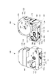
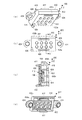
- FIG. 4 is a plan view (a), a back view (b), a front view (c), a back view (d), a left side view (e), and a right side view (f) of the tape cartridge according to the embodiment.
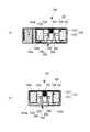
- FIG. 3 is a cross-sectional view taken along line AA in FIG. 2A and a cross-sectional view taken along line BB.
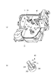
- It is the top view (a) and perspective view (b) which show the pattern reading part periphery of a tape printer.
- FIG. 4 is a perspective view (a), a front view (b) and a cross-sectional view taken along the line AA ′ (c) showing the sensor unit of the tape printer, and a rear perspective view (d) of the sensor holder. It is the perspective view which looked at the opening-and-closing lid from the back side.
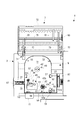
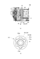
- FIG. 2A is a plan view of the tape cartridge with the upper case and the upper case removed, and FIG. It is an expanded sectional view (a) of a platen drive shaft and a platen roller, and an enlarged view (b) of the spline engagement part.
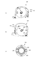
- FIG. 4 is a perspective view (a) of the cartridge mounting portion and an enlarged perspective view (b) around the base convex portion.
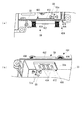
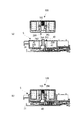
- FIG. 4 is a cross-sectional view (a) in a non-mounted state with respect to a cartridge mounting portion of the tape cartridge, and a cross-sectional view (b) in a mounted state. They are sectional drawing (a) of the non-mounting state with respect to the cartridge mounting part of a tape cartridge, and sectional drawing (b) of a mounting state (1st modification). They are sectional drawing (a) of the non-mounting state with respect to the cartridge mounting part of a tape cartridge, and sectional drawing (b) of a mounting state (2nd modification).
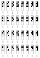
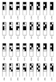
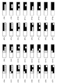
- the top view which shows the example of a combination of the identification part in a to-be-detected part.
- the top view which shows the example of a combination of the identification part in a to-be-detected part.
- the top view which shows the example of a combination of the identification part in a to-be-detected part.
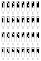
- the top view which shows the example of a combination of the identification part in a to-be-detected part which shows the example of a combination of the identification part in a to-be-detected part.
- the top view which shows the example of a combination of the identification part in a to-be-detected part.
- the top view which shows the example of a combination of the identification part in a to-be-detected part.
- the top view which shows the example of a combination of the identification part in a to-be-detected part.
- This tape printing apparatus performs printing while feeding out a printing tape and an ink ribbon from a mounted tape cartridge, cuts a printed portion of the printing tape, and creates a label (tape piece).
- FIG. 1 is an external perspective view of a tape printer and a tape cartridge attached to the tape printer.
- the tape printer 1 includes an apparatus case 3 constituting an outer shell, a cartridge mounting part 5 to which a tape cartridge 100 is detachably mounted, and an opening / closing lid 7 for opening and closing the cartridge mounting part 5. It is equipped with.
- a cartridge mounting portion 5 is provided on the back side
- a display 11 is provided in the center
- a keyboard 13 is provided on the front side.
- a finger hanging recess 15 is provided, and the open / close lid 7 is opened so as to spring up through the recess 15.
- a vertical tape discharge port 17 through which the printing tape 102 is discharged is provided on the side surface (left side surface) of the device case 3.
- the tape printer 1 includes a printing mechanism unit 23 having a print head 21 erected on the cartridge mounting unit 5, a tape feeding mechanism unit 25 built in the back side space of the cartridge mounting unit 5, and a tape discharge port 17. And a tape cutting mechanism 27 built in the vicinity.
- the user inputs print information from the keyboard 13, confirms the print information on the display 11, and then executes printing by key operation.
- the tape feeding mechanism unit 25 is driven to cause the printing tape 102 and the ink ribbon 110 to run side by side, and printing by thermal transfer is performed by the printing mechanism unit 23.
- the print tape 102 is discharged from the tape discharge port 17, and when printing is completed, the tape cutting mechanism unit 27 is driven and the printed portion of the print tape 102 is cut off.
- the tape cartridge 100 includes a tape roll 106 in which the printing tape 102 is wound around the tape core 104, and a ribbon roll 114 in which the ink ribbon 110 is wound around the feeding core 112. .
- the tape cartridge 100 also includes a take-up core 116 that winds up the used ink ribbon 110, and a platen roller that the print head 21 contacts with the ink ribbon 110 and the print tape 102 and sends the print tape 102 and the ink ribbon 110. 120 (platen).
- the tape cartridge 100 includes a cartridge case 130 that accommodates the tape roll 106, the ribbon roll 114, the winding core 116, and the platen roller 120.
- the tape cartridge 100 of this embodiment has a so-called shell structure in which the outer shell is covered with the cartridge case 130.
- the cartridge case 130 is formed with an insertion opening 134 into which the print head 21 is inserted when the tape cartridge 100 is attached to the tape printer 1.
- the tape cartridge 100 includes a tape delivery port 138 that is formed in the cartridge case 130 and through which the printing tape 102 is delivered.
- the tape roll 106 is rotatably supported by a cylindrical core shaft portion 192 projecting from the inside of the cartridge case 130 (see FIG. 4).
- the printing tape 102 is fed out from the tape core 104, and the ink ribbon 110 is fed out from the feeding core 112.
- the fed printing tape 102 and ink ribbon 110 run side by side at the platen roller 120 and are used for printing by the print head 21.
- the feeding end portion (printed portion) of the printing tape 102 on which printing has been performed is sent out from the tape delivery port 138 toward the tape discharge port 17.
- the ink ribbon 110 wraps around the peripheral wall portion of the insertion opening 134 and is wound around the winding core 116.
- the tape cartridge 100 is prepared with a plurality of types having different thicknesses according to the tape width of the printing tape 102.
- the cartridge mounting portion 5 is formed in a planar shape complementary to the planar shape of the tape cartridge 100, and the tape cartridge having the maximum thickness among a plurality of types of tape cartridges 100 that can be mounted.
- a recess corresponding to 100 is formed.
- the mounting base 31 and the side plate portion 33 constituting the bottom plate portion of the cartridge mounting portion 5 are integrally formed (molded) with resin or the like.
- a slit-like tape discharge path 35 is formed between the cartridge mounting portion 5 and the tape discharge port 17, and the tape cutting mechanism portion 27 is built in this portion.
- a base convex portion serving as an identification means is fitted into the mounting base 31 of the cartridge mounting portion 5 when the inner peripheral portion of the core shaft portion 192 (see FIG. 4) of the tape cartridge 100 is fitted when the tape cartridge 100 is mounted. 40 is erected. Although details will be described later, the base convex portion 40 includes a circular pedestal portion 41 erected on the mounting base 31 and an identification convex portion 42 erected on the pedestal portion 41.
- the mounting base 31 is provided with a print head 21 covered with a head cover 43, a platen drive shaft 45 that rotationally drives the platen roller 120, and a winding drive shaft 47 that rotationally drives the winding core 116. Has been.
- the mounting base 31 located near the winding drive shaft 47 releases the tape detection unit 51 that detects the type (attribute information) of the printing tape 102, and the rotation stop of the feeding core 112 and the winding core 116.
- a core releasing portion 53 that is provided.
- the mounting base 31 is provided with a pair of small protrusions 55 at diagonal positions, and in addition, a pair of latching pieces 57 for latching the intermediate portion of the mounted tape cartridge 100.
- the tape feeding mechanism 25 having a motor and a gear train (both not shown) for rotating the platen drive shaft 45 and the take-up drive shaft 47 is incorporated.
- the tape feeding mechanism 25 divides the power by the gear train and rotates the platen drive shaft 45 and the take-up drive shaft 47 synchronously.
- a reading unit 59 is provided.
- the tape detection unit 51 detects (recognizes) the tape width of the printing tape 102 accommodated in the tape cartridge 100, and the pattern reading unit 59 excludes the tape width, and the type information of the tape cartridge 100. (Tape color and material of the accommodated printing tape 102, ribbon color of the accommodated ink ribbon 110, etc.) are recognized. Details of the bit patterns (type reading patterns) of the pattern reading unit 59 and the type reading seal 143 will be described later.
- the print mechanism unit 23 includes a print head 21 formed of a thermal head, a head support frame 61 that supports and rotates the print head 21, and a print position and a retracted position of the print head 21 via the head support frame 61. And a head cover 43 that covers the print head 21 (and the head support frame 61).
- the head release mechanism operates in conjunction with the opening / closing of the opening / closing lid 7, moves (rotates) the print head 21 to the printing position in conjunction with the closing operation of the opening / closing lid 7, and prints in conjunction with the opening operation.
- the head 21 is moved (turned) to the retracted position.
- the print head 21 that has moved to the printing position comes into contact with the platen roller 120 of the tape cartridge 100 via the ink ribbon 110 and the print tape 102, and the print head 21 that has moved to the retracted position is separated from the platen roller 120.
- the print head 21 is provided with a plurality of heating elements, and the plurality of heating elements are arranged in the same direction as the axial direction of the platen roller 120. Then, printing is performed by feeding the printing tape 102 and the ink ribbon 110 and selectively driving a plurality of heating elements.
- the head cover 43 is formed in a substantially rectangular shape in plan view, and is formed (molded) integrally with the mounting base 31 (cartridge mounting portion 5). The head cover 43 protrudes vertically from the mounting base 31 and allows the print head 21 to rotate inside thereof.
- the tape detection unit 51 includes a plurality of microswitches 51a, and selectively engages with a detection unit 180 (see FIG. 3) of the tape cartridge 100, which will be described later. The type of material is detected. Based on the detection result, the driving of the print head 21 and the tape feeding mechanism 25 is controlled.
- the core releasing part 53 is composed of two releasing pins 53 a for the feeding core 112 and the winding core 116.
- the cartridge case 130 is provided with a rotation-preventing hook 206 that is hooked on the feeding core 112 and the winding core 116, respectively (see FIG. 9).
- the release pin 53a is engaged with the rotation stop hook 206, and the rotation stop of the feeding core 112 and the take-up core 116 is released.
- the platen drive shaft 45 includes a fixed support shaft 48 provided so as to pass through the platen roller 120, a spline-shaped spline drive shaft 49 (drive shaft) rotatably supported on a base portion of the fixed support shaft 48, (See FIG. 5 and FIG. 10).
- the rotational power of the tape feeding mechanism 25 is transmitted to the spline drive shaft 49 and further transmitted from the spline drive shaft 49 to the platen roller 120 (details will be described later).
- the winding drive shaft 47 includes a fixed shaft 47a and a spline-shaped movable shaft 47b that is rotatably supported by the fixed shaft 47a. Also in this case, the rotational power of the tape feeding mechanism 25 is transmitted to the movable shaft 47b, and further transmitted from the movable shaft 47b to the winding core 116.
- the core shaft portion 192 (a core recess portion 260 described later) is engaged with the base convex portion 40 (see FIG. 13), and the platen roller 120 is engaged with the platen drive shaft 45. Further, the winding core 116 is engaged with the winding drive shaft 47.
- the print head 21 rotates and contacts the platen roller 120 with the print tape 102 and the ink ribbon 110 interposed therebetween, and the tape printer 1 enters a print standby state.
- the opening / closing lid 7 is rotatably attached to the device case 3 through the hinge portion 71 provided on the back side, that is, can be opened and closed.
- the opening / closing lid 7 has an opening / closing lid body 73 and a viewing window 75 provided at the center of the opening / closing lid body 73.
- the open / close lid 7 protrudes from the back surface of the open / close lid body 73 and is pivotally supported by the hinge portion 71 so as to be pivotally supported. And an actuating lever 79 for rotating the.
- the opening / closing lid 7 protrudes on the back surface of the opening / closing lid body 73 and pushes the tape cartridge 100 into two push projections 81, and protrudes on the back surface of the opening / closing lid body 73, and has a built-in lid closing detection switch (not shown). And a pressing projection 83 for actuating (ON).
- the viewing window 75 is formed in a horizontally long shape and is made of a transparent (transparent to visible light) resin that is separate from the opening / closing lid body 73. Through this viewing window 75, the tape cartridge 100 mounted on the cartridge mounting portion 5 can be visually recognized (type of printing tape 102 and remaining tape amount). Further, the pair of shaft support pieces 77, the operating lever 79, the two pushing projections 81 and the pushing projection 83, and the opening / closing lid body 73 are integrally formed (molded) with resin.
- the operating lever 79 protrudes greatly from the back surface of the opening / closing lid body 73 and is inserted into a slit opening 87 provided on the side of the cartridge mounting portion 5 when the opening / closing lid 7 is closed.
- the operating lever 79 inserted into the slit opening 87 operates the above-described head release mechanism and rotates the print head 21 toward the platen roller 120.
- the pressing protrusion 83 is inserted into the rectangular opening 91 adjacent to the slit opening 87 as the opening / closing lid 7 is closed, and turns on the lid closing detection switch.
- One pushing protrusion 81 corresponds to a position in the vicinity of the platen roller 120 of the tape cartridge 100, and the other pushing protrusion 81 corresponds to a position immediately above the tape detection unit 51.
- the two pushing protrusions 81 push the tape cartridge 100 so that the tape cartridge 100 is seated on the mounting base 31 of the cartridge mounting portion 5 and prevent the tape cartridge 100 from being lifted.
- the tape cartridge 100 will be described in detail with reference to FIGS. 2 to 4 and FIG.
- the front surface on the front side of the tape cartridge 100 in the mounting direction is “front surface”
- the reverse side in the mounting direction is “back surface”
- the left side is referred to as the “left side surface”
- the right side surface as the “right side surface”
- the upper arc-shaped side surface as the “front end surface”
- the lower side surface as the “base end surface”.
- the tape cartridge 100 includes the cartridge case 130 and the tape roll 106, the ribbon roll 114, the winding core 116, and the platen roller 120 accommodated therein (see FIG. 9). Further, the tape cartridge 100 includes an insertion opening 134 formed in the cartridge case 130, a tape outlet 138 formed on the left side in the vicinity of the platen roller 120, the surface of the part in which the tape roll 106 is accommodated, the left side, And an identification seal 141 (see FIG. 1) attached over the right side surface. On the identification seal 141, the tape width, tape color, material, and the like (part of attribute information) of the accommodated printing tape 102 are displayed at two locations on the front surface and the left side surface.
- the cartridge case 130 constitutes the outline of the tape cartridge 100 (shell structure), and has an “L” -shaped appearance in plan view with the proximal end side of the right side surface protruding somewhat.
- the cartridge case 130 has a lower case 150 that is the back side when mounted on the cartridge mounting portion 5 and an upper case 152 that is the front side.
- the upper case 152 is formed of a transparent resin molded product
- the lower case 150 is formed of an opaque resin molded product.
- the upper case 152 is integrally formed (molded) with a top wall portion 156 constituting the surface of the cartridge case 130 and an upper peripheral wall portion 158 provided vertically on the peripheral edge portion of the top wall portion 156.
- the lower case 150 includes a bottom wall portion 160 constituting the back surface of the cartridge case 130, a lower peripheral wall 162 erected on the periphery of the bottom wall portion 160, and a bottom wall portion so as to define the insertion opening 134. And an opening peripheral wall portion 164 erected on 160.
- a plurality of joining pins 170 are provided at appropriate intervals on the lower end surface of the upper peripheral wall portion 158 in the upper case 152, while a plurality of joining pins corresponding to the plurality of joining pins 170 are provided on the lower peripheral wall 162 of the lower case 150.
- a hole 172 is provided (see FIG. 9). After setting components such as the tape roll 106 and the ribbon roll 114 in the lower case 150, the upper case 152 is joined so that the plurality of joining pins 170 are press-fitted into the plurality of joining holes 172. Assembled.
- Each joint hole 172 is a through hole in consideration of ease of molding.
- a pair of latch receiving portions 174 that are latched by the pair of latch pieces 57 are provided on the left side surface and the right side surface of the lower case 150 (FIGS. 2E and 2F). (Refer FIG.3 (b)).
- the pair of latching pieces 57 on the cartridge mounting unit 5 side are latched on the pair of latching receiving portions 174 of the mounted tape cartridge 100, thereby preventing the tape cartridge 100 from being lifted.
- a fitting small hole 176 into which the pair of small protrusions 55 are fitted with some margin is provided on the back surface of the lower case 150 (see FIG. 3B).
- a tape detected portion 180 corresponding to the tape detecting portion 51 is provided in the left corner portion on the base end surface side (right corner portion when viewed from the front surface side). (See FIG. 3B).
- the tape detection unit 180 is configured in a portion corresponding to the plurality of microswitches 51a of the tape detection unit 51, and a plurality of bit patterns are obtained depending on the presence or absence of the receiving holes 180a provided in this portion. That is, this bit pattern corresponds to the type of the print tape 102 described above.
- the tape cartridge 100 includes a type display sticker 141 (see FIG. 1) attached to the surface, left side, and right side of the portion in which the tape roll 106 is accommodated, and a lower case 150 of the cartridge case 130.
- a type reading seal 143 (see FIG. 2C and FIG. 3) as a detected portion attached to the base end face 150a is provided.
- the type display seal 141 displays type information of the tape cartridge 100 (tape width, tape color, material, etc. of the accommodated printing tape 102).
- the type reading seal 143 as a detected part is provided with a bit configuration unit 145, and the bit configuration unit 145 stores the type information of the tape cartridge 100 (the tape color and material of the stored printing tape 102).
- An identification unit 147 constituting a bit pattern (type read pattern) indicating the ribbon color of the ink ribbon 110 is disposed (see FIG. 16). Details of the bit configuration unit 145 and the identification unit 147 constituting the bit pattern (type read pattern) will be described later.
- the reading seal sticking part 175 for sticking the said kind reading seal 143 may be formed in the base end surface 150a of the lower case 150.
- the reading sticker attaching portion 175 is a concave portion formed in a rectangular shape with respect to the base end surface 150a so as to have a depth corresponding to the thickness of the type reading sticker 143 (or more than the thickness). The reading sticker 175 prevents the type reading sticker 143 from protruding from the base end face 150a.
- a tape storage area 190 in which the tape roll 106 is widely stored is formed in the upper space (tip surface side) in the cartridge case 130.
- a core shaft portion 192 that is integrally formed (formed) with the lower case 150 is erected in the center of the tape housing area 190.
- the core shaft portion 192 is formed in a stepped cylindrical shape, and a tape roll 106 (tape core 104) is rotatably supported on the outer peripheral surface 192b (see FIG. 4).
- a core concave portion 260 in which the above-described base convex portion 40 is fitted is formed on the inner peripheral side of the core shaft portion 192 formed in a stepped cylindrical shape.
- the core concave portion 260 includes a depressed portion 262 into which the base portion 41 of the base convex portion 40 is fitted, and an identification concave portion 264 as fitting means into which the identification convex portion 42 is fitted.
- a reverse rotation preventing spring 193 of the tape roll 106 made of a coil spring is incorporated in the upper portion of the core recess 260.
- a tape guide 194 that guides the fed printing tape 102 to the platen roller 120 is erected integrally with the lower case 150 in the tape storage area 190 located in the vicinity of the platen roller 120.
- a tape feed path 196 starting from the tape roll 106 and passing through the tape guide 194 and the platen roller 120 to the tape feed outlet 138 is configured inside the cartridge case 130.
- the printing tape 102 fed out from the tape roll 106 is guided to the platen roller 120 through the tape guide 194, used for printing, and further guided from the platen roller 120 to the tape delivery port 138.
- the tape roll 106 has a printing tape 102 and a tape core 104 and two circular films 198 attached to both end faces of the roll-shaped printing tape 102.
- the two circular films 198 prevent the printing tape 102 wound around the tape core 104 from being scattered.
- the tape core 104 includes a reel portion 104a around which the printing tape 102 is wound, a rolling contact portion 104c provided inside the reel portion 104a via a plurality of inward ribs 104b, And is rotatably supported on the core shaft portion 192 by the rolling contact portion 104c.
- a plurality of radial end face grooves 104d are formed on the end face of the rolling contact portion 104c, and the above-described reverse rotation prevention spring 193 is engaged with and disengaged from the end face groove 104d.
- a longitudinal slit 192a extending in the axial direction is formed at the upper portion of the core shaft portion 192, and the end of the wire rod of the reverse rotation preventing spring 193 protrudes from the longitudinal slit 192a and is engaged with the end face groove 104d of the rolling contact portion 104c.
- the reverse rotation spring 193 prevents the tape roll 106 (printing tape 102) from being reversed.
- the above-described base convex portion 40 compresses the anti-reverse spring 193, and the end of the wire rod is detached from the end face groove 104d of the rolling contact portion 104c, and the reverse rotation is released. (See FIG. 13 for both). As a result, the printing tape 102 can be fed.
- a ribbon accommodating area 200 is formed adjacent to the insertion opening 134.
- a feeding side bearing portion 202 that rotatably supports the ribbon roll 114 (feeding core 112) is provided, and on the left side, a winding side bearing portion that rotatably supports the winding core 116 is provided.
- 204 are formed integrally with the cartridge case 130, respectively. That is, the feeding side bearing portion 202 and the winding side bearing portion 204 are formed on the upper case 152 and the lower case 150, respectively.
- the rotation prevention hook 206 with the tip portion facing the feeding side bearing portion 202 and the take-up side bearing portion 204 is provided. Are integrally formed.
- One rotation stop hook 206 is engaged with the feeding core 112, and the other rotation stop hook 206 is engaged with the winding core 116 in a rotation stopped state.
- a first ribbon guide 210 for guiding the fed ink ribbon 110 to the platen roller 120 is erected integrally with the lower case 150 in the ribbon accommodating area 200 located in the vicinity of the feeding side bearing portion 202.
- a plurality of second ribbon guides 212 that guide the circumference of the ink ribbon 110 are integrally formed on the outer peripheral side of the opening peripheral wall portion 164.
- a ribbon feed path 214 starting from the ribbon roll 114, passing through the first ribbon guide 210, the platen roller 120, and the plurality of second ribbon guides 212 to the winding core 116 is configured inside the cartridge case 130. Yes.
- the ink ribbon 110 fed out from the ribbon roll 114 is guided to the platen roller 120 through the first ribbon guide 210 and used for printing, and further from the platen roller 120 to the opening peripheral wall 164 (a plurality of second ribbon guides). 212) is wound around the winding core 116.
- the ribbon roll 114 includes an ink ribbon 110 and a feeding core 112 and an annular leaf spring 220 that applies a braking load to the feeding core 112 (see FIG. 9B).
- the leaf spring 220 is formed in a wave shape in the circumferential direction, and is interposed between the top wall portion 156 of the upper case 152 and the feeding core 112 in the axial direction. That is, a rotational braking load is applied to the feeding core 112 by the elastic force of the leaf spring 220. As a result, the back tension is applied to the ink ribbon 110 fed out by the take-up core 116, and the slack is prevented.
- the feeding core 112 is formed in a cylindrical shape, and a plurality of cutouts 222 are formed in the circumferential direction at the end on the lower case 150 side (see FIG. 3B).
- the rotation stop hook 206 is engaged with and disengaged from the plurality of notches 222.
- the feeding-side bearing portion 202 on the lower case 150 side that supports the feeding core 112 is configured with a circular opening, whereas the feeding-side bearing portion 202 on the upper case 152 side is configured with a cylindrical protruding portion. Yes.
- plate spring 220 is mounted
- the winding core 116 is formed in a cylindrical shape, and a plurality of notches 224 are formed in the circumferential direction at the end portion on the lower case 150 side (see FIG. 3B).
- the rotation stop hook 206 is engaged with and disengaged from the plurality of notches 224.
- a spline-like slit groove 226 is formed on the inner peripheral surface of the winding core 116 and engages with the winding drive shaft 47 by spline. Thereby, the rotational force of the winding drive shaft 47 is transmitted to the winding core 116, and the ink ribbon 110 is wound up.
- a platen accommodation area 230 is formed adjacent to the insertion opening 134 on the left side of the base in the cartridge case 130.
- the platen roller 120 is supported by the upper bearing portion 232 and the lower bearing portion 234 so as to be rotatable and slightly laterally movable.
- the platen roller 120 supported by the elliptical upper bearing portion 232 and the lower bearing portion 234 has a home position that engages with the platen drive shaft 45 and a sandwich position that sandwiches the printing tape 102 and contacts the tape guide 194. It is configured to be capable of lateral movement (small movement).
- the tape cartridge 100 is carried in a state in which the feeding end portion of the printing tape 102 is slightly protruded to the outside from the tape delivery port 138 (see FIG. 1). At that time, if a pressing force or a pulling force acts on the feeding end portion of the printing tape 102 by mistake, the platen roller 120 dragged by this moves to the clamping position. Thereby, the feeding end portion of the printing tape 102 is prevented from being drawn into the cartridge case 130 from the tape delivery port 138.
- the platen roller 120 has a cylindrical roller base 240 and a rubber roller 242 attached to the outer peripheral surface of the roller base 240 (see FIG. 10).
- the rubber roller 242 has a length corresponding to the print head 21 in the axial direction, and the print head 21 that has moved to the print position sandwiches the print tape 102 and the ink ribbon 110 and contacts the rubber roller 242.
- a spline boss portion 244 as a fitting portion is formed at the base portion of the roller base 240, and the spline drive shaft 49 (drive shaft) of the platen drive shaft 45 is spline engaged with the spline boss portion 244. (See FIG. 10). Thereby, the rotational force of the platen drive shaft 45 is transmitted to the platen roller 120, and the printing tape 102 (and the ink ribbon 110) is printed and fed.
- the structure of the core concave portion 260 and the platen roller 120 of the tape cartridge 100 will be described in detail together with the base convex portion 40 and the platen drive shaft 45 of the cartridge mounting portion 5 with reference to FIGS.
- the cartridge mounting portion 5 is provided with the platen drive shaft 45 and the base convex portion 40 so as to be separated from each other.
- the plate cartridge roller 120 and the core concave portion 260 are provided on the tape cartridge 100. It has been.
- the platen drive shaft 45 is rotatably supported by a fixed support shaft 48 erected on the device frame 270 located below the mounting base 31 and a lower portion of the fixed support shaft 48. And a spline drive shaft 49.
- the fixed support shaft 48 is fixed to the apparatus frame 270 in a cantilever manner and extends in the attaching / detaching direction of the tape cartridge 100 through the mounting base 31.
- the spline drive shaft 49 has a base gear portion 272 and a spline shaft portion 274 extending from the gear portion 272, and the gear train of the tape feeding mechanism portion 25 is connected to the gear portion 272.
- the platen roller 120 has the roller base 240 and the rubber roller 242 as described above, and the spline boss portion 244 is formed at the base of the roller base 240. That is, the roller base 240 is formed with a spline boss portion 244 that is spline-engaged with the spline shaft portion 274 described above.
- the fixed support shaft 48 of the platen drive shaft 45 is inserted into the roller base 240 of the platen roller 120. Further, the spline shaft portion 274 of the platen drive shaft 45 is engaged with the spline boss portion 244 of the platen roller 120.
- the spline shaft portion 274 is formed with a plurality of spline teeth 274a in the circumferential direction, and the spline boss portion 244 has a plurality of spline grooves 244a corresponding to the plurality of spline teeth 274a. Is formed.
- the number of spline grooves 244a is larger than the number of teeth of the spline teeth 274a.
- the circumferential intervals of the plurality of spline grooves 244a are formed larger than the circumferential intervals of the plurality of spline teeth 274a.
- the number of spline grooves 244a is six and the number of spline teeth 274a is three, and the spline teeth 274a mesh with every other spline groove 244a.
- the inner peripheral surface base part of the spline boss part 244 is chamfered, and has a so-called invitation shape (see FIG. 10A).
- the spline shaft part 274 is smoothly fitted (engaged) with the spline boss part 244. That is, the tape cartridge 100 is smoothly mounted on the cartridge mounting portion 5.
- the base convex portion 40 is integrally formed with a pedestal portion 41 erected on the mounting base 31 and an identification convex portion 42 erected on the pedestal portion 41.
- the pedestal portion 41 is formed in a circular shape, and has a notch opening 280 in a part of the circumferential direction thereof.
- the identification convex portion 42 includes a columnar (hollow) convex main body 282, four protrusions 284 provided in a cross shape on the outer peripheral surface of the convex main body 282, and a base from the convex main body 282. And a tongue piece 286 projecting in the radial direction so as to follow the upper surface of the portion 41.
- the core concave portion 260 has a depressed portion 262 into which the base portion 41 of the base convex portion 40 is fitted, and an identification concave portion 264 into which the identification convex portion 42 is fitted. ing.
- the depressed portion 262 and the identification concave portion 264 constitute an integral space.
- the identification recess 264 is provided with a fitting protrusion 290 (protrusion) corresponding to the notch opening 280 so as to protrude in the axial direction toward this space.
- the identification recess 264 is provided with a fitting recess 292 corresponding to the tongue piece 286 of the identification projection 42 so as to be immersed from this space.
- the pedestal portion 41 of the base convex portion 40 fits into the recessed portion 262 of the core concave portion 260, and at the same time, the identification convex portion 42 of the base convex portion 40 identifies the core concave portion 260. It fits into the recess 264 (see FIG. 13).
- the fitting convex portion 290 is fitted into the notch opening 280 and the tongue piece 286 is fitted into the fitting concave portion 292.
- the tape roll 106 is extremely heavy among the components, and the center of gravity exists near the tape core 104 in plan view. For this reason, when the tape cartridge 100 is gripped at the time of mounting, the tape cartridge 100 tends to be inclined downward and tilted unless otherwise noted. In such a case, before the identification convex portion 42 is fitted into the identification concave portion 264, the identification convex portion 42 is likely to abut against the depressed portion 262, thereby correcting the posture of the inclined tape cartridge 100. That is, since the tape cartridge 100 is corrected to a horizontal posture at the time of mounting, the mounting can be performed smoothly (details will be described later).
- the cartridge type can be identified by the cooperation of the core concave portion 260 and the base convex portion 40.
- the cartridge type is not the type of the print tape 102 (the tape type is determined by the tape detection unit 51), and for example, the use (industrial use or home use), the destination area (for the US or Europe), etc. are identified. .
- the plurality of types of tape cartridges for each destination region (for each use) in which the positions of the fitting recesses 292 in the core recesses 260 are shifted in the circumferential direction by, for example, 90 ° pitch (the phase is shifted). 100 is prepared.
- a plurality of types of tape printers 1 for each destination region (for each use), in which the phase of the tongue piece 286 of the base convex portion 40 is shifted, are prepared (first identification pattern). .
- a pattern in which the phase of the fitting convex portion 290 in the core concave portion 260 is shifted is also added.
- (Second identification pattern) instead of shifting the phase (first identification pattern and / or second identification pattern) or in addition to shifting the phase, the fitting recess 292 (tongue piece 286) and the fitting projection 290 (notch) The shape of the opening 280) may be changed.
- the identification concave portion 264 is disposed in the depressed portion 262, and therefore the identification concave portion 264 is fitted to the identification convex portion 42 of the base convex portion 40 at the time of mounting.
- the identification convex portion 42 once strikes the depressed portion 262 and the posture of the tape cartridge 100 is corrected. For this reason, before the identification recessed part 264 starts fitting to the identification convex part 42, possibility that the spline boss
- the fitting of the spline boss portion 244 precedes the identification concave portion 264, so that the inclination and position of the tape cartridge 100 can be corrected at the start of mounting. Furthermore, by providing a timing difference between the start of fitting of the spline boss portion 244 and the start of fitting of the identification recess 264, the impact force at the time of mounting can be dispersed. Therefore, the tape cartridge 100 can be smoothly mounted on the mounting portion of the tape printer 1.
- the identification recess 264 is provided in the depressed portion 262, the identification recess 264 (core shaft portion 192) can be substantially shortened, and an appropriate strength can be provided. Moreover, the identification recess 264 is less likely to receive a direct impact force against a drop impact or the like. Therefore, the identification recess 264 can be structured to be difficult to break. Furthermore, even if there is a protrusion such as a fitting convex portion 290 in the identification concave portion 264 due to the depressed portion 262, this does not protrude from the outer surface of the tape cartridge 100, and when the tape cartridge 100 is stored in a stack, The convex part 290 etc. do not get in the way.
- a cartridge detection unit 300 (actuated portion) is incorporated in the base convex portion 40.
- the cartridge detection unit 300 is operated using the fitting convex part 290 of the core concave part 260 as an operation part, and detects the proper mounting of the tape cartridge 100 in the cartridge type. Therefore, the fitting convex part 290 in the first modification also functions as a detected part on the tape cartridge 100 side.
- the cartridge detection unit 300 is incorporated in the base portion 41 of the base convex portion 40, and the actuated member 302 that moves downward from the fitting convex portion 290 that is the actuating portion, and contacts the actuated member 302 from below.
- a switch main body 304 is configured by a micro switch or the like that is fixedly provided.
- the actuated member 302 is formed in a cap shape, and is provided on the inner peripheral surface of the pedestal portion 41 so as to be movable up and down.
- the fitting convex portion 290 of the core concave portion 260 comes into contact with the actuated member 302 via the notch opening portion 280 of the base convex portion 40 and moves it downward.
- the switch body 304 is actuated (ON) by the downward movement of the actuated member 302, and attachment of the tape cartridge 100 is detected.
- the cartridge detection unit 300 by providing the cartridge detection unit 300 in the base convex portion 40, it is detected that the tape cartridge 100 for each destination region (for each use) is properly mounted. Can do.
- the cartridge detection unit 300 has a structure for operating the switch body 304 via the operated member 302, and the operated member 302 is formed in a cap shape, so that a notch opening 280 for cartridge identification is provided. Even if the position or shape of the cartridge is changed, it is not necessary to make a change on the cartridge detection unit 300 side.
- the tape cartridge 100 has a destination area (use) such as a cold district
- an operation such as switching the tape printer 1 to the cold district mode is performed based on the detection result of the cartridge detection unit 300. May be.
- the actuated member 302A has a structure also serving as the tongue piece 286. Therefore, in the second modification, the fitting recess 292 of the core recess 260 corresponding to the tongue piece 286 functions as a detected portion on the tape cartridge 100 side.
- the actuated member 302A is integrally formed of a shaft-shaped portion 310 and a tongue-shaped portion 312 that also serves as a tongue piece 286.
- the shaft-shaped portion 310 is provided on the inner peripheral surface of the convex portion main body 282 in the base convex portion 40 so as to be movable up and down.
- the tongue-like portion 312 is provided to be movable up and down in an L-shaped slit portion 316 provided from the side surface of the convex body 282 to the upper surface of the pedestal portion 41.
- the tongue portion 312 is set to a position where the initial position is somewhat higher than the tongue piece 286 in consideration of the operation stroke.
- the fitting recess 292 (the top surface) of the core recess 260 comes into contact with the tongue-shaped portion 312 of the operated member 302A, and moves the operated member 302A downward.
- the switch body 304 is actuated (ON) by the downward movement of the actuated member 302A, and the attachment of the tape cartridge 100 is detected.
- the cartridge detection unit 300 in the base convex portion 40, it is detected that the tape cartridge 100 for each destination region (for each use) is properly mounted. Can do. Further, since the actuated member 302A has a structure that also serves as the tongue piece 286, the number of components can be reduced.
- the pattern reading unit 59 as a detection unit is provided on the front side of the side plate portion 33 of the cartridge mounting unit 5 and is disposed facing the inside of the cartridge mounting unit 5. That is, the pattern reading unit 59 is disposed at a position facing the base end surface of the tape cartridge 100 (base end surface 150 a of the lower case 150) when the tape cartridge 100 is mounted on the cartridge mounting unit 5.
- the pattern reading unit 59 includes a sensor unit 400 disposed toward the inside of the cartridge mounting unit 5, a unit support unit 402 that supports the sensor unit 400 movably, and the sensor unit 400 inside the cartridge mounting unit 5.
- a unit urging unit 404 that urges the unit.
- the unit support portion 402 is provided in an opening portion 33 a opened in the side plate portion 33 of the cartridge mounting portion 5, and supports the sensor unit 400 movably inside and outside the cartridge mounting portion 5.
- the unit urging portion 404 has a pair of left and right coil springs 406, and urges a pair of spring receiving portions 424 (described later) provided in the sensor unit 400 by the pair of coil springs 406. That is, the unit urging portion 404 urges the sensor unit 400 to the inside of the cartridge mounting portion 5 via the pair of spring receiving portions 424 by the pair of coil springs 406. Due to the urging, the sensor unit 400 protrudes to the inside of the cartridge mounting portion 5 when the tape cartridge 100 is not mounted. When the tape cartridge 100 is mounted, the sensor unit 400 is biased toward the tape cartridge 100 and the sensor unit 400 is pressed against the base end surface of the tape cartridge 100.
- the sensor unit 400 includes a sensor unit 410 (detection unit) in which a plurality of optical sensors 409 are mounted on a sensor substrate 408, and a sensor holder 412 (holder) in which the sensor unit 410 is mounted. Yes.
- the sensor substrate 408 is attached to the base end portion of the sensor holder 412 in a vertical posture.
- the sensor substrate 410 is attached to the sensor holder 412, so that the sensor holder 412 holds the sensor unit 410.
- the plurality of optical sensors 409 are arranged in a matrix of 2 rows and 4 columns on the sensor substrate 408, as in the bit configuration unit 145 (see FIG. 3) (see FIG. 7B).
- Each of the plurality of optical sensors 409 is configured by a light reflection type optical non-contact sensor, which irradiates each bit component 145 (identification unit 147) with detection light and each bit component 145 ( The reflected light from the identification unit 147) is received.
- the identification unit 147 in each bit configuration unit 145 indicates bit information depending on whether or not black ink is printed in the white print area, and each optical sensor 409 receives each bit.
- the black ink of the identification unit 147 is printed on the bit configuration unit 145 depending on the presence / absence of reflected light from the configuration unit 145 (identification unit 147) (strictly, the amount of light is a certain amount or more). Whether or not the identification unit 147 is provided) is detected, and the bit information indicated by the bit configuration unit 145 is read based on the detection result.
- the sensor unit 410 reads the bit pattern of each bit configuration unit 145 by the plurality of optical sensors 409, thereby reading the bit pattern and reading the type information of the tape cartridge 100 corresponding to the bit pattern.
- the sensor holder 412 includes a holder body 420 having a trapezoidal shape in side view, a pair of upper and lower substrate mounting hooks 422 protruding from the holder body 420 toward the base end side, and a pair of left and right springs protruding left and right from the base end portion of the holder body 420.
- a receiving portion 424, a positioning pin 426 (engaged portion) provided on the right front side of the holder main body 420, and a connecting portion 428 for connecting the positioning pin 426 and the holder main body 420 are provided.
- the holder body 420, the pair of board mounting hooks 422, the pair of spring receiving portions 424, the positioning pins 426, and the connecting portion 428 are integrally formed (molded) with resin or the like.
- the pair of substrate attachment hooks 422 are for attaching the sensor substrate 408 to the sensor holder 412. That is, the sensor substrate 408 is attached to the sensor holder 412 by the pair of substrate attachment hooks 422.
- the pair of spring receiving portions 424 are portions where the ends of the pair of coil springs 406 are in contact with each other and receive the urging force of the pair of coil springs 406.
- the pair of spring receiving portions 424 hits the side plate portion 33 of the cartridge mounting portion 5 and functions as a front end restricting portion that restricts the front end in the movement of the sensor unit 400.
- the holder body 420 includes a holder cover 430 that covers the entire plurality of optical sensors 409 and a partition member 432 that individually surrounds each optical sensor 409.
- a plurality of sensor holes 434 corresponding to the plurality of optical sensors 409 are formed at the tip of the holder cover 430.
- Each optical sensor 409 emits detection light from each sensor hole 434, and receives reflected light from the bit configuration unit 145 from each sensor hole 434.
- the holder cover 430 functions as an external light blocking unit that blocks external light to each optical sensor 409.
- the partition member 432 functions as an interference preventing unit that blocks detection light from the adjacent optical sensors 409 and prevents interference between the optical sensors 409.
- the holder cover 430 not only functions as an external light shielding unit, but also abuts on the base end surface of the tape cartridge 100 to provide a predetermined clearance between the sensor unit 410 (each optical sensor 409) and the bit configuration unit 145. It also functions as a spacer for clearance. That is, the front end surface 430 a of the holder cover 430 is a contact surface with the base end surface of the tape cartridge 100.
- the predetermined clearance is formed between the sensor unit 410 and the bit configuration unit 145 by contacting and closely contacting the base end surface of the sensor 100.
- the front end surface 430a of the holder cover 430 is formed to be slightly inclined forward and downward so as to follow the base end surface of the tape cartridge 100.
- an invitation slope 430b that is inclined downward is formed on the front side.
- the invitation inclined surface 430b abuts against the back side end of the tape cartridge 100, and a part of the force (component force) for mounting the tape cartridge 100 is used. 5 to act as a force to push back to the outside of 5.
- the sensor unit 400 is pushed back against the unit urging unit 404 as the tape cartridge 100 is mounted. Accordingly, when the mounting of the tape cartridge 100 is completed, the sensor unit 400 is pressed against the tape cartridge 100.
- bit configuration unit 145 provided in the type reading seal 143 as the detected unit and the bit pattern (type reading pattern) formed in the bit configuration unit 145 are configured.
- the identification unit 147 will be described.
- the type reading seal 143 has a type reading pattern indicating the type information of the tape cartridge 100 (tape color and material of the stored printing tape 102, ribbon color of the stored ink ribbon 110, etc.).
- a bit configuration portion 145 is formed as a region to be formed.
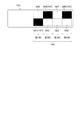
- the bit configuration unit 145 has eight areas bit1 to area bit8 arranged in a matrix of 2 rows and 4 columns. In the area bit1 to area bit8, a bit pattern (type read pattern) in which the identification unit 147 is arranged is configured.
- the identification unit 147 indicates 1-bit bit information depending on whether or not black ink is printed (solid printing) in a white print area. In other words, the bit information is represented by binary numbers by plain / painting for each of the area bit1 to area bit8 of the bit configuration unit 145. That is, a total of eight identification units 147 indicate an 8-bit bit pattern (type read pattern).
- the bit configuration unit 145 having an 8-bit bit pattern (type reading pattern) and the pattern reading unit 59 (see FIGS. 5 and 6) serving as the detection unit described above do not perform scanning reading.
- Various types of information of the tape cartridge 100 can be read. That is, it is possible to read various types of information of the tape cartridge 100 simply and in a short time without bothering the wearer (user).
- bit1 and bit5 are the first column
- bit2 and bit6 are the second column
- bit3 and bit7 are the third column
- bit4 and bit8 are the fourth column.
- four ribbon colors are identified by the bit pattern of the first column
- 16 tape colors are identified by the bit pattern of the second column and the fourth column
- four tape widths are identified by the bit pattern of the third column.
- bit pattern As a combination example (bit pattern) of the arrangement of the identification unit 147 in the bit configuration unit 145, it can have an 8-bit bit pattern (type read pattern) as described above.
- bit pattern a combination example (bit pattern) of the arrangement of the identification unit 147 is specifically listed. 256 patterns from pattern A0 (see FIG. 17) to pattern P15 (see FIG. 24) can be provided. An arbitrary pattern can be selected from such 256 patterns and used as the type information of the tape cartridge 100.
- the broken line indicating the outer edge of the bit configuration unit 145 in FIG. 16 is shown for the sake of convenience of description to indicate the area of the bit configuration unit 145, and may not be actually formed, or instead of the broken line.
- Other line types such as a solid line may be used.
- the identification unit 147 has been described by exemplifying a configuration in which black ink is printed (solid printing) in the entire area (area bit1 to area bit8) of each bit configuration unit 145.
- the configuration is not limited to this configuration. Absent.
- the identification unit 147 includes, for example, a circular identification unit 147a printed with black ink (solid printing), a triangular identification unit 147b printed with black ink (solid printing), and black ink.
- any configuration that can be distinguished from the white bit configuration unit 145 such as an oval (track shape) identification unit 147f that has been printed (solid print), may be used.
- the identification unit 147 is not limited to the above-described modification example, and is a bit configuration unit in which the identification unit 147 is not provided, such as another polygon, an ellipse, or a shape having an outer shape in which a straight line part and a curved part are combined. It is possible to apply a configuration that can be discriminated from 145.
- the spline boss portion 244 as the fitting portion of the tape cartridge 100 and the spline drive shaft 49 (drive shaft) of the platen drive shaft 45 of the tape printer 1 are spline-engaged, A tape cartridge 100 is loaded.
- the tape cartridge 100 and the holder (cartridge mounting portion 5) are integrated, and the position of the type reading seal 143 (bit configuration portion 145) as the detected portion is determined as a detection portion.
- the position of the pattern reading unit 59 is positioned. Thereby, the positional relationship between the pattern reading unit 59 and the type reading sticker 143 (bit configuration unit 145) can be set to an optimal positional relationship.
- the detection unit is configured so as to face the type reading seal 143 (bit configuration unit 145) as the detected unit disposed on the wall surface that follows the mounting direction of the tape cartridge 100. Since the pattern reading unit 59 is disposed, the distance between the pattern reading unit 59 and the type reading sticker 143 (the bit constituting unit 145) can be shortened, and is affected by the positional deviation between the tape cartridge and the holder. Can be difficult. That is, it is possible to maintain an optimal positional relationship between the pattern reading unit 59 and the type reading seal 143 (bit configuration unit 145).
- the positional relationship between the pattern reading unit 59 and the type reading sticker 143 (bit configuration unit 145) can be set to an optimal positional relationship, and the optimal positional relationship can be maintained, so that the pattern reading can be performed.
- the detection capability of the unit 59 can be improved, and the type information of the tape cartridge can be read accurately.
- the bit configuration unit 145 and the optical sensor 409 are each configured to be 8 in 2 rows and 4 columns.
- the number and arrangement (the number of rows and the number of columns) of these are described here. It is not limited.
- the configuration may be such that six are arranged in one row and six columns, or may be the configuration that are arranged in a vertical manner such as six in six rows and one column. Further, the number of rows and the number of columns may be the same as 16 pieces of 4 rows and 4 columns.
- the bit configuration unit 145 indicates 1-bit bit information depending on whether or not black ink is printed (solid print) in the white print area.
- the color of the ink and the color of the ink to be printed are not limited to this as long as the bit information can be detected by the optical sensor 409 (if the presence or absence or intensity of reflected light when the detection light is irradiated can be detected).
- 1-bit bit information may be indicated depending on whether white ink is printed in a black print area.
- one of the colors of the print area and the ink color may be a blue, amber, and green color, and the other may be a red, yellow, and orange color.
- the type reading seal 143 as the detected portion in which the bit pattern (type reading pattern) in which the identification unit 147 is arranged in the bit configuration unit 145 is formed is attached to the side surface (bottom surface 150a) of the tape cartridge 100. ), And the bit configuration portion 145 is provided on the side surface (bottom surface 150a) of the tape cartridge 100. However, the bit configuration portion 145 is formed directly on the side surface (bottom surface 150a) of the tape cartridge 100. There may be.
- a configuration may be used in which a bit pattern (type read pattern) is printed (drawn) by the bit configuration unit 145 in which the identification unit 147 is disposed on the side surface, or a bit in which the identification unit 147 is disposed on the side surface.
- the bit pattern (type read pattern) by the configuration unit 145 may be engraved (drawn) with a laser or the like.
- a configuration may be employed in which a bit pattern (type read pattern) is formed (drawn) by the bit configuration unit 145 in which the identification unit 147 is disposed by selectively forming an opening for each identification unit 147.
Landscapes
- Impression-Transfer Materials And Handling Thereof (AREA)
- Printers Characterized By Their Purpose (AREA)
- Handling Of Continuous Sheets Of Paper (AREA)
- Electronic Switches (AREA)
Abstract
Description
テープカートリッジには、側面部に、印刷用テープや印刷用インクの仕様を識別するための仕様表示シールが装着されている。そして、テープ印刷装置の複数のフォトインタラプター(光学センサー)は、このテープカートリッジをカートリッジ装着部に装着したとき、仕様表示シールに対峙するように配設され、仕様表示シールに形成された仕様表示部に、黒インクが印刷されているか否かを検出し、この検出結果に基づいて、上記仕様を識別する。
本適用例のテープカートリッジは、テープカートリッジに配設された被検出部に検出光を照射して前記被検出部から前記テープカートリッジの種別情報を読み取る検出部を備えたテープ印刷装置に対し、着脱方向に着脱されるテープカートリッジであって、前記脱着方向に倣う壁面に配設された前記被検出部と、装着方向奥側の壁面から配設された嵌合部と、を備え、前記被検出部は、前記嵌合部に沿って装着されたときに前記検出部と対峙する位置に配設されていることを特徴とする。
また、テープカートリッジが装着された場合に、該テープカートリッジの装着方向に倣う壁面に配設された被検出部と対峙するように検出部が配設されているため、被検出部と検出部との距離を短縮することができ、テープカートリッジとホルダーとの位置ずれの影響を受け難くすることができる。すなわち、検出部と被検出部との最適な位置関係を維持することができる。このように、検出部と被検出部との位置関係を最適な位置関係にすることができると共に、当該最適な位置関係を維持することができることで、検出部による検出能力を向上させることができ、テープカートリッジの種別情報を正確に読み取らせることができる。
なお、ここで被検出部が、前述の背景技術における仕様表示部(仕様表示シール)に相当する。
上記適用例に記載のテープカートリッジにおいて、前記被検出部は、ビット構成部を備えていることが好ましい。
上記適用例に記載のテープカートリッジにおいて、前記ビット構成部は、マトリックス状に配置されていることが好ましい。
上記適用例に記載のテープカートリッジにおいて、前記被検出部は、前記ビット構成部に配設された前記識別部の組み合わせによって、前記種別情報を構成していることが好ましい。
上記適用例に記載のテープカートリッジにおいて、前記被検出部は、前記壁面に貼着されていることが好ましい。
上記適用例に記載のテープカートリッジにおいて、前記被検出部は、前記壁面に描画されていることが好ましい。
図1は、テープ印刷装置およびこれに装着されるテープカートリッジの外観斜視図である。同図に示すように、テープ印刷装置1は、外殻を構成する装置ケース3と、テープカートリッジ100が着脱自在に装着されるカートリッジ装着部5と、カートリッジ装着部5を開閉する開閉蓋7と、を備えている。装置ケース3の上面には、奥側にカートリッジ装着部5が設けられ、中央にディスプレイ11が設けられ、手前側にキーボード13が設けられている。開閉蓋7の近傍には、指掛け用の窪入部15が設けられており、開閉蓋7は、この窪入部15を介して跳ね上げるように開放される。そして、装置ケース3の側面(左側面)には、印刷テープ102が排出される縦長のテープ排出口17が設けられている。
図2および図9に示すように、テープカートリッジ100は、印刷テープ102をテープコア104に巻回したテープロール106と、インクリボン110を繰出しコア112に巻回したリボンロール114と、を備えている。また、テープカートリッジ100は、使用後のインクリボン110を巻き取る巻取りコア116と、印刷ヘッド21がインクリボン110および印刷テープ102を介して当接すると共に印刷テープ102およびインクリボン110を送るプラテンローラー120(プラテン)と、を備えている。さらに、テープカートリッジ100は、これらテープロール106、リボンロール114、巻取りコア116およびプラテンローラー120を収容したカートリッジケース130を備えている。このように、本実施形態のテープカートリッジ100は、外殻をカートリッジケース130で覆われた、いわゆるシェル構造を有している。
図1および図5に示すように、カートリッジ装着部5は、テープカートリッジ100の平面形状と相補的な平面形状に形成されると共に、装着可能な複数種のテープカートリッジ100うち、最大厚のテープカートリッジ100に対応する深さを有して、窪入形成されている。この場合、カートリッジ装着部5の底板部を構成する装着ベース31と側板部33とは、樹脂等で一体に形成(成形)されている。カートリッジ装着部5と上記のテープ排出口17との間には、スリット状のテープ排出経路35が形成されており、この部分に、上記のテープ切断機構部27が内蔵されている。
次に、図2ないし図4、および図9を参照して、テープカートリッジ100について詳細に説明する。なお、テープカートリッジ100の説明では、図1を例に、テープカートリッジ100の上正面である装着方向手前の面を「表面」と、逆側の装着方向奥側の面を「裏面」と、左側の側面を「左側面」と、右側の側面を「右側面」と、上側の円弧状の側面を「先端面」と、下側の側面を「基端面」と、称呼するものとする。
一方、被検出部としての種別読取シール143には、ビット構成部145が設けられ、このビット構成部145に、テープカートリッジ100の種別情報(収容された印刷テープ102のテープ色、材質、収容されたインクリボン110のリボン色等)を示すビットパターン(種別読取パターン)を構成する識別部147が配置されている(図16参照)。なお、ビット構成部145、およびビットパターン(種別読取パターン)を構成する識別部147の詳細については、後述する。
次に、図10ないし図13を参照して、テープカートリッジ100のコア凹部260およびプラテンローラー120の構造について、カートリッジ装着部5のベース凸部40およびプラテン駆動軸45と共に詳細に説明する。上述のように、カートリッジ装着部5には、相互に離間してプラテン駆動軸45およびベース凸部40が設けられ、これに対応して、テープカートリッジ100にはプラテンローラー120およびコア凹部260が設けられている。
次に、図14を参照して、上記実施形態の第1変形例について説明する。同図に示すように、この第1変形例では、ベース凸部40の内部にカートリッジ検出部300(被作動部)を組み込むようにしている。このカートリッジ検出部300は、上記コア凹部260の嵌合凸部290を作動部として作動され、上記のカートリッジ種別における適正なテープカートリッジ100の装着を検出する。したがって、第1変形例における嵌合凸部290は、テープカートリッジ100側の被検出部としても機能する。
次に、図15を参照して、上記実施形態の第2変形例について説明する。同図に示すように、この第2変形例では、ベース凸部40の内部に組み込まれたカートリッジ検出部300において、被作動部材302Aが舌片286を兼ねる構造を有している。したがって、第2変形例では、舌片286に対応するコア凹部260の嵌合凹部292が、テープカートリッジ100側の被検出部として機能する。
次に、図5ないし図7を参照して、検出部としてのパターン読取部59について説明する。図5および図6に示すように、検出部としてのパターン読取部59は、カートリッジ装着部5の側板部33の手前側に設けられ、カートリッジ装着部5の内側を向いて配設されている。すなわち、パターン読取部59は、テープカートリッジ100をカートリッジ装着部5に装着したときに、テープカートリッジ100の基端面(下ケース150の基端面150a)に対向する位置に配設されている。パターン読取部59は、カートリッジ装着部5の内側に向いて配設されたセンサーユニット400と、センサーユニット400を移動自在に支持するユニット支持部402と、センサーユニット400をカートリッジ装着部5の内側に付勢するユニット付勢部404と、を備えている。
次に、図16ないし図24を参照して、被検出部としての種別読取シール143に設けられたビット構成部145、およびビット構成部145に形成されるビットパターン(種別読取パターン)を構成する識別部147について説明する。
次に、図25を参照して、識別部の変形例について説明する。上述では、識別部147として、それぞれのビット構成部145の領域(領域bit1~領域bit8)全体に黒インクが印刷(べた印刷)された構成を例示して説明したが、この構成に限るものではない。識別部147としては、図25に示すように、例えば、黒インクで印刷(べた印刷)された円形の識別部147a、黒インクで印刷(べた印刷)された三角形の識別部147b、黒インクで印刷(べた印刷)された四角形の識別部147c、黒インクで印刷(べた印刷)された五角形の識別部147d、黒インクで印刷(べた印刷)された六角形の識別部147e、もしくは黒インクで印刷(べた印刷)された長円形状(トラック形状)の識別部147fのように、白地のビット構成部145との判別が可能な構成であればよい。なお、識別部147としては、前述の変形例に限らず、他の多角形、楕円、もしくは直線部と曲線部とを組み合わせた外形を有する形状など、識別部147が設けられていないビット構成部145との判別が可能な構成を適用することできる。また、識別部147の他の構成例としては、図25に示すように、例えば、交差する複数の直線で構成された格子模様の識別部147hや黒字に白抜きの円形が設けられた識別部147gなど、識別部147が設けられていないビット構成部145との判別が可能な構成であれば適用することが可能である。
Claims (6)
- テープカートリッジに配設された被検出部に検出光を照射して前記被検出部から前記テープカートリッジの種別情報を読み取る検出部を備えたテープ印刷装置に対し、着脱方向に着脱されるテープカートリッジであって、
前記脱着方向に倣う壁面に配設された前記被検出部と、
装着方向奥側の壁面から配設された嵌合部と、を備え、
前記被検出部は、前記嵌合部に沿って装着されたときに前記検出部と対峙する位置に配設されていることを特徴とするテープカートリッジ。 - 前記被検出部は、ビット構成部を備えていることを特徴とする請求項1に記載のテープカートリッジ。
- 前記ビット構成部は、マトリックス状に配置されていることを特徴とする請求項2に記載のテープカートリッジ。
- 前記被検出部は、前記ビット構成部に配設された前記識別部の組み合わせによって、前記種別情報を構成していることを特徴とする請求項2または請求項3に記載のテープカートリッジ。
- 前記被検出部は、前記壁面に貼着されていることを特徴とする請求項1ないし請求項4のいずれか一項に記載のテープカートリッジ。
- 前記被検出部は、前記壁面に描画されていることを特徴とする請求項1ないし請求項4のいずれか一項に記載のテープカートリッジ。
Priority Applications (9)
| Application Number | Priority Date | Filing Date | Title |
|---|---|---|---|
| PCT/JP2015/001909 WO2016157256A1 (ja) | 2015-04-03 | 2015-04-03 | テープカートリッジ |
| KR1020197018506A KR102032486B1 (ko) | 2015-04-03 | 2015-04-03 | 테이프 카트리지 |
| US15/563,866 US10144229B2 (en) | 2015-04-03 | 2015-04-03 | Tape cartridge |
| KR1020197028034A KR102065499B1 (ko) | 2015-04-03 | 2015-04-03 | 테이프 카트리지 |
| CN201910628137.4A CN110254057B (zh) | 2015-04-03 | 2015-04-03 | 带盒 |
| KR1020177030576A KR101995803B1 (ko) | 2015-04-03 | 2015-04-03 | 테이프 카트리지 |
| JP2017508797A JP6394789B2 (ja) | 2015-04-03 | 2015-04-03 | テープカートリッジ |
| CN201580078144.1A CN107405934B (zh) | 2015-04-03 | 2015-04-03 | 带盒 |
| KR1020207000356A KR102099715B1 (ko) | 2015-04-03 | 2015-04-03 | 테이프 카트리지 |
Applications Claiming Priority (1)
| Application Number | Priority Date | Filing Date | Title |
|---|---|---|---|
| PCT/JP2015/001909 WO2016157256A1 (ja) | 2015-04-03 | 2015-04-03 | テープカートリッジ |
Publications (1)
| Publication Number | Publication Date |
|---|---|
| WO2016157256A1 true WO2016157256A1 (ja) | 2016-10-06 |
Family
ID=57004000
Family Applications (1)
| Application Number | Title | Priority Date | Filing Date |
|---|---|---|---|
| PCT/JP2015/001909 Ceased WO2016157256A1 (ja) | 2015-04-03 | 2015-04-03 | テープカートリッジ |
Country Status (5)
| Country | Link |
|---|---|
| US (1) | US10144229B2 (ja) |
| JP (1) | JP6394789B2 (ja) |
| KR (4) | KR102032486B1 (ja) |
| CN (2) | CN107405934B (ja) |
| WO (1) | WO2016157256A1 (ja) |
Cited By (2)
| Publication number | Priority date | Publication date | Assignee | Title |
|---|---|---|---|---|
| CN108528072A (zh) * | 2017-03-01 | 2018-09-14 | 精工爱普生株式会社 | 带打印装置 |
| CN114953762A (zh) * | 2021-02-18 | 2022-08-30 | 精工爱普生株式会社 | 信息处理装置及其控制方法、带印刷系统、以及记录介质 |
Families Citing this family (7)
| Publication number | Priority date | Publication date | Assignee | Title |
|---|---|---|---|---|
| CN115447290B (zh) * | 2018-03-29 | 2023-11-03 | 精工爱普生株式会社 | 色带盒 |
| CN115447291B (zh) * | 2018-03-29 | 2023-11-07 | 精工爱普生株式会社 | 色带盒以及印刷装置 |
| US11884062B2 (en) | 2020-04-09 | 2024-01-30 | Zebra Technologies Corporation | Media cartridge |
| JP7604825B2 (ja) | 2020-09-30 | 2024-12-24 | ブラザー工業株式会社 | 印刷用カセット及び印刷装置 |
| US11548302B2 (en) * | 2020-10-15 | 2023-01-10 | Zebra Technologies Corporation | Media cartridge and media processing device engagement mechanisms |
| JP7563220B2 (ja) * | 2021-02-16 | 2024-10-08 | セイコーエプソン株式会社 | 情報処理装置、テープ印刷装置、テープ印刷システム、情報処理装置の制御方法およびプログラム |
| JP2024099367A (ja) * | 2023-01-12 | 2024-07-25 | セイコーエプソン株式会社 | リボンカートリッジ |
Citations (3)
| Publication number | Priority date | Publication date | Assignee | Title |
|---|---|---|---|---|
| JPH0939347A (ja) * | 1995-07-27 | 1997-02-10 | Seiko Epson Corp | テープカートリッジおよびテープライタ |
| JP2007230153A (ja) * | 2006-03-02 | 2007-09-13 | Sony Corp | インクリボンカートリッジ及びプリンタ装置 |
| JP2013141749A (ja) * | 2012-01-06 | 2013-07-22 | Brother Industries Ltd | テープカセット及び印字ラベル作成システム |
Family Cites Families (13)
| Publication number | Priority date | Publication date | Assignee | Title |
|---|---|---|---|---|
| JP2749075B2 (ja) | 1988-10-03 | 1998-05-13 | 株式会社日立製作所 | 熱転写記録装置及びインク紙カセット |
| JP4521890B2 (ja) * | 1998-06-24 | 2010-08-11 | カシオ計算機株式会社 | 印刷装置 |
| WO2005086882A2 (en) * | 2004-03-10 | 2005-09-22 | Kroy Llc | Tape printing apparatus and method of printing |
| EP1955856B1 (en) * | 2007-02-09 | 2013-04-10 | Brother Kogyo Kabushiki Kaisha | Tape printer, tape printing program and tape cassette |
| PT2370265E (pt) * | 2008-12-25 | 2013-10-04 | Brother Ind Ltd | Cassete de fita e impressora de fita |
| CN104691118B (zh) * | 2009-03-31 | 2017-10-13 | 兄弟工业株式会社 | 带盒 |
| DK2414165T3 (da) * | 2009-03-31 | 2014-05-05 | Brother Ind Ltd | Båndkassette og båndprinter |
| US20100329767A1 (en) * | 2009-06-30 | 2010-12-30 | Brother Kogyo Kabushiki Kaisha | Tape cassette |
| JP2011037155A (ja) * | 2009-08-12 | 2011-02-24 | Seiko Epson Corp | テープ供給装置およびこれを備えたテープ印刷装置 |
| EP2390099B1 (en) * | 2010-05-31 | 2016-04-20 | Brother Kogyo Kabushiki Kaisha | Printer |
| JP5857677B2 (ja) * | 2011-11-25 | 2016-02-10 | ブラザー工業株式会社 | テープ印刷装置 |
| CN202965543U (zh) * | 2012-12-14 | 2013-06-05 | 鼎翰科技股份有限公司 | 卡匣模块 |
| US9333776B2 (en) * | 2013-07-16 | 2016-05-10 | Esselte Ipr Ab | Cartridge for label printer |
-
2015
- 2015-04-03 CN CN201580078144.1A patent/CN107405934B/zh active Active
- 2015-04-03 KR KR1020197018506A patent/KR102032486B1/ko active Active
- 2015-04-03 KR KR1020197028034A patent/KR102065499B1/ko active Active
- 2015-04-03 JP JP2017508797A patent/JP6394789B2/ja active Active
- 2015-04-03 CN CN201910628137.4A patent/CN110254057B/zh active Active
- 2015-04-03 KR KR1020177030576A patent/KR101995803B1/ko active Active
- 2015-04-03 US US15/563,866 patent/US10144229B2/en active Active
- 2015-04-03 WO PCT/JP2015/001909 patent/WO2016157256A1/ja not_active Ceased
- 2015-04-03 KR KR1020207000356A patent/KR102099715B1/ko active Active
Patent Citations (3)
| Publication number | Priority date | Publication date | Assignee | Title |
|---|---|---|---|---|
| JPH0939347A (ja) * | 1995-07-27 | 1997-02-10 | Seiko Epson Corp | テープカートリッジおよびテープライタ |
| JP2007230153A (ja) * | 2006-03-02 | 2007-09-13 | Sony Corp | インクリボンカートリッジ及びプリンタ装置 |
| JP2013141749A (ja) * | 2012-01-06 | 2013-07-22 | Brother Industries Ltd | テープカセット及び印字ラベル作成システム |
Cited By (4)
| Publication number | Priority date | Publication date | Assignee | Title |
|---|---|---|---|---|
| CN108528072A (zh) * | 2017-03-01 | 2018-09-14 | 精工爱普生株式会社 | 带打印装置 |
| CN108528072B (zh) * | 2017-03-01 | 2020-01-17 | 精工爱普生株式会社 | 带打印装置 |
| CN114953762A (zh) * | 2021-02-18 | 2022-08-30 | 精工爱普生株式会社 | 信息处理装置及其控制方法、带印刷系统、以及记录介质 |
| CN114953762B (zh) * | 2021-02-18 | 2023-06-23 | 精工爱普生株式会社 | 信息处理装置及其控制方法、带印刷系统、以及记录介质 |
Also Published As
| Publication number | Publication date |
|---|---|
| US10144229B2 (en) | 2018-12-04 |
| KR20190077135A (ko) | 2019-07-02 |
| KR102099715B1 (ko) | 2020-04-10 |
| KR20170129259A (ko) | 2017-11-24 |
| CN110254057A (zh) | 2019-09-20 |
| CN107405934B (zh) | 2019-07-26 |
| KR20190111166A (ko) | 2019-10-01 |
| US20180117935A1 (en) | 2018-05-03 |
| KR102032486B1 (ko) | 2019-10-15 |
| CN110254057B (zh) | 2021-07-13 |
| KR20200004925A (ko) | 2020-01-14 |
| CN107405934A (zh) | 2017-11-28 |
| JPWO2016157256A1 (ja) | 2017-10-26 |
| JP6394789B2 (ja) | 2018-09-26 |
| KR101995803B1 (ko) | 2019-07-03 |
| KR102065499B1 (ko) | 2020-01-13 |
Similar Documents
| Publication | Publication Date | Title |
|---|---|---|
| JP6394789B2 (ja) | テープカートリッジ | |
| JP6397719B2 (ja) | テープカートリッジ | |
| JP6508904B2 (ja) | テープカートリッジ | |
| JP6561492B2 (ja) | テープ印刷装置およびテープ印刷システム | |
| JP2020073319A (ja) | テープカートリッジ | |
| JP2018184007A (ja) | テープカートリッジ | |
| JP6543979B2 (ja) | テープ印刷装置 | |
| JP6535796B2 (ja) | テープカートリッジ | |
| JP6754861B2 (ja) | テープカートリッジ |
Legal Events
| Date | Code | Title | Description |
|---|---|---|---|
| 121 | Ep: the epo has been informed by wipo that ep was designated in this application |
Ref document number: 15887413 Country of ref document: EP Kind code of ref document: A1 |
|
| ENP | Entry into the national phase |
Ref document number: 2017508797 Country of ref document: JP Kind code of ref document: A |
|
| WWE | Wipo information: entry into national phase |
Ref document number: 15563866 Country of ref document: US |
|
| NENP | Non-entry into the national phase |
Ref country code: DE |
|
| ENP | Entry into the national phase |
Ref document number: 20177030576 Country of ref document: KR Kind code of ref document: A |
|
| 122 | Ep: pct application non-entry in european phase |
Ref document number: 15887413 Country of ref document: EP Kind code of ref document: A1 |