WO2016152859A1 - クラッチ機構および洗濯機用モータユニット - Google Patents
クラッチ機構および洗濯機用モータユニット Download PDFInfo
- Publication number
- WO2016152859A1 WO2016152859A1 PCT/JP2016/058996 JP2016058996W WO2016152859A1 WO 2016152859 A1 WO2016152859 A1 WO 2016152859A1 JP 2016058996 W JP2016058996 W JP 2016058996W WO 2016152859 A1 WO2016152859 A1 WO 2016152859A1
- Authority
- WO
- WIPO (PCT)
- Prior art keywords
- rotating body
- motor
- clutch mechanism
- rotor
- frame member
- Prior art date
- Legal status (The legal status is an assumption and is not a legal conclusion. Google has not performed a legal analysis and makes no representation as to the accuracy of the status listed.)
- Ceased
Links
Images
Classifications
-
- D—TEXTILES; PAPER
- D06—TREATMENT OF TEXTILES OR THE LIKE; LAUNDERING; FLEXIBLE MATERIALS NOT OTHERWISE PROVIDED FOR
- D06F—LAUNDERING, DRYING, IRONING, PRESSING OR FOLDING TEXTILE ARTICLES
- D06F37/00—Details specific to washing machines covered by groups D06F21/00 - D06F25/00
- D06F37/30—Driving arrangements
- D06F37/40—Driving arrangements for driving the receptacle and an agitator or impeller, e.g. alternatively
-
- D—TEXTILES; PAPER
- D06—TREATMENT OF TEXTILES OR THE LIKE; LAUNDERING; FLEXIBLE MATERIALS NOT OTHERWISE PROVIDED FOR
- D06F—LAUNDERING, DRYING, IRONING, PRESSING OR FOLDING TEXTILE ARTICLES
- D06F39/00—Details of washing machines not specific to a single type of machines covered by groups D06F9/00 - D06F27/00
Definitions
- the present invention relates to a clutch mechanism and a motor unit for a washing machine including the clutch mechanism.
- Patent Documents 1 and 2 listed below disclose a washing machine motor unit including a clutch mechanism that interrupts transmission of driving force from a motor to a rotating tub.
- the clutch operating mechanism for operating the clutch 14 of Patent Document 1 is driven from the drive motor 10 to the inner tub 6 by moving the sleeve 54 up and down by the operating lever 66 and engaging and separating the sleeve 54 from the locking bracket 74. To interrupt power transmission.
- the sleeve 54 is rotatably supported by the fork portion 80 of the operating lever 66, and the sleeve 54 moves in the vertical direction when the actuator 65 swings the operating lever 66.
- the support member 34 on which the second rotator 20 is rotatably supported is moved up and down by the support member moving mechanism 35, and the second rotator 20 is engaged with and separated from the first rotator 13. By doing so, transmission of the driving force from the motor 5 to the laundry basket 3 is interrupted.
- the support member 34 is rotated in the circumferential direction by the synchronous motor 37 of the support member moving mechanism 35 and its reduction gear train 63, and further moves in the vertical direction together with the second rotating body 20 by the action of the cam mechanism 39.
- the clutch mechanism 7 of Patent Document 2 can be mounted in a smaller space than the clutch operating mechanism of Patent Document 1.
- the clutch mechanism 7 of Patent Document 2 uses the synchronous motor 37 that rotates only in one direction, the clutch disengaged state and the disengaged state must be repeated in sequence, and the clutch disengaged state is unknown. , It is not possible to switch directly to the desired state. Therefore, the clutch mechanism 7 of Patent Document 2 is separately provided with a detection mechanism 40 using a tact switch 71 and a washing tub rotation detection device 8 using a Hall IC 85, and disconnection is performed while determining the state of the clutch. I have control.
- the motor 5 of Patent Document 2 is arranged separately from the clutch mechanism 7.
- the motor 5 is a direct drive motor and the clutch mechanism 7 is accommodated therein, the space inside the motor is not sufficient. Since it is divided into parts such as a stator, the restriction on the arrangement space of the clutch mechanism 7 becomes more severe.
- the clutch mechanism 7 is accommodated in such a narrow arrangement space, the sizes of the synchronous motor 37, the reduction wheel train 63, the detection mechanism 40, the washing tub rotation detection device 8 and the like constituting the clutch mechanism 7 become a problem. .
- the problem to be solved by the present invention is a clutch mechanism that can be arranged even in a narrow arrangement space, and that can directly switch the clutch disengagement state.
- the object is to provide a motor unit for a washing machine in which a clutch mechanism is housed.
- a clutch mechanism includes a first rotating body and a second rotating body that are coaxially arranged and engageable with each other, and the second rotating body is displaced in the axial direction.
- a lift mechanism that switches engagement / separation between the second rotating body and the first rotating body, and a case in which the second rotating body and the lift mechanism are accommodated.
- a second motor rotatable in both directions, the second motor including a cylindrical second rotor and a second stator, and the second rotating body includes the second rotor and the second rotor
- the gist is that it is arranged inside the second stator.
- the clutch mechanism By disposing the second rotating body inside the second motor that is the driving source of the clutch mechanism, the number of parts for transmitting the output of the driving source to the second rotating body can be minimized. As a result, the clutch mechanism can be reduced in size, and the reliability can be improved by reducing the number of parts.
- the lift mechanism further displaces the frame member in the axial direction according to the rotation direction of the second motor and the frame member that rotatably supports the second rotating body.
- a cam mechanism to be arranged, and the frame member and the cam mechanism may be further arranged inside the second rotor and the second stator.
- the lift mechanism includes a frame member and a cam mechanism, and these are arranged inside the second rotor and the second stator, whereby the mechanism necessary for the clutch mechanism to displace the second rotating body in the axial direction. All of these can be accommodated inside the second rotor and the second stator. Thereby, the external shape of a clutch apparatus can be made into the disk shape or column shape without the protrusion part to an axial direction or radial direction.
- the second motor is a stepping motor.
- the rotation angle can be controlled by the number of steps, so there is no need to provide a mechanism for determining the lifting / lowering state of the frame member and a feedback mechanism for the motor rotation number, and the clutch mechanism can be made compact. Can be achieved. Furthermore, the stepping motor is highly reliable because it has few contact parts.
- the second motor is an inner rotor type motor
- the frame member is supported by the case so as not to rotate in the circumferential direction
- the cam mechanism is formed on the outer peripheral surface of the frame member. It is good also as a structure which consists of the protrusion part which is the provided cam follower, and the helical cam groove provided in the internal peripheral surface of said 2nd rotor in which this protrusion part is inserted.
- the clutch mechanism can be further reduced in size and improved in reliability.
- the second rotor is supported by a roller member or a ball member provided in the case so as to be rotatable in the circumferential direction.
- the second rotor can be rotated with a smaller force.
- the fixed-side teeth projecting toward the second rotating body at a portion of the case where the second rotating body spaced apart from the first rotating body contacts the axial direction thereof.
- a fixed-side tooth portion that meshes with the fixed-side tooth portion is formed at a portion of the second rotating body that faces the fixed-side tooth portion, and the second rotating body is in a separated position thereof.
- the fixed side tooth portion and the fixed side tooth portion mesh with each other so as to be non-rotatably locked to the case, and the frame member includes an inner peripheral portion that supports the second rotating body, An outer peripheral portion that supports an inner peripheral portion, the outer peripheral portion supports the inner peripheral portion in an axial direction via a biasing member, and the inner peripheral portion is supported by the biasing member.
- At least the height of the fixed side tooth portion, axially relative to the outer peripheral portion It is desirable that can be displaced.
- the motor unit for a washing machine of the present invention includes a first motor, the first motor includes a cylindrical first rotor and a first stator, and the first rotor and the first motor
- the clutch mechanism according to any one of claims 1 to 6 is arranged inside the stator of the first and second aspects, and the first rotating body is rotationally driven by the first motor. To do.
- the clutch device of the present invention can save space by having the above-described configuration. By accommodating the clutch device inside the first motor, the arrangement space of the clutch device can be further reduced, and the operation of attaching the washing machine motor unit to the washing machine can be simplified.
- the outer shape of the clutch mechanism of the present invention can be a disc shape or a cylindrical shape, it is suitable for being arranged inside the cylindrical first rotor and the first stator.
- the clutch mechanism breaks down in such a configuration, the clutch mechanism is housed inside the first motor, so that repair and replacement may be complicated.
- the clutch mechanism according to the present invention the number of parts is reduced and the failure rate is suppressed. Therefore, the above disadvantageous effect is compensated, and the advantageous effect of reducing the arrangement space becomes remarkable.
- a rotating shaft that rotates integrally with the first rotating body is erected at the rotation center of the first rotating body, and the rotating shaft is splined on the outer peripheral surface.
- the tip of the rotating shaft is exposed from the cylindrical shaft, and the second rotating body is fitted into the spline portion, so that the spline portion of the spline portion is inserted. It is movable in the axial direction and rotates integrally with the cylindrical shaft in the circumferential direction.
- the clutch mechanism can be arranged even in a narrow arrangement space, and can directly switch the clutch disengagement state, and A motor unit for a washing machine in which such a clutch mechanism is accommodated can be provided.
- FIG. 1 It is sectional drawing which shows schematic structure of the fully automatic electric washing machine provided with the motor unit for washing machines of this invention. It is an external appearance perspective view of a motor unit. It is a disassembled perspective view of a motor unit and a clutch mechanism. It is a perspective view explaining the raising / lowering operation of the frame member by a lift mechanism. It is sectional drawing explaining the raising / lowering operation of the frame member by a lift mechanism.
- the motor unit for the washing machine according to the present embodiment is mounted on a spiral type fully automatic electric washing machine, and the clutch mechanism performs both a washing operation for rotating only the pulsator according to the washing process of clothes, and both the pulsator and the rotating tub. Switching between rotating and dehydrating operations. Note that “upper”, “lower”, and “vertical direction” in the present embodiment refer to the vertical direction shown in FIG.
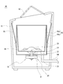
- FIG. 1 is a cross-sectional view showing a schematic configuration of a fully automatic electric washing machine 90 (hereinafter simply referred to as “washing machine 90”) according to the present embodiment.
- the washing machine 90 has a rectangular tube-shaped casing 91 having a cover 92 that can be opened and closed at an opening on the upper surface. Inside the casing 91 is a bottomed cylindrical inner tank that constitutes a washing and dehydrating tank 95. 95a and outer tub 95b and a washing machine motor unit 10 (hereinafter simply referred to as “motor unit 10”) are accommodated.
- motor unit 10 a washing machine motor unit 10
- the outer tub 95b is suspended from the housing 91 by a suspension bar 93 having a buffer mechanism, and a drain pipe 94 for discharging washing water to the outside is connected to the bottom of the outer tub 95b.
- the inner tank 95a which is a rotating tank is rotatably supported in the outer tank 95b, and a pulsator 96 is installed at the center of the bottom surface.
- the pulsator 96 and the inner tub 95 a are connected to the motor unit 10 disposed below the washing / dehydrating tub 95.
- the rotating shaft 20 of the motor unit 10 has a tip portion passing through the bottom surface of the inner tank 95 a and connected to the pulsator 96, and the pulsator 96 rotates integrally with the rotating shaft 20.
- the cylindrical shaft 21 of the motor unit 10 is connected to the lower surface of the inner tank 95 a via the connecting member 22, and the inner tank 95 a rotates integrally with the cylindrical shaft 21.
- the fixing member 23 of the motor unit 10 is attached to the lower surface of the outer tub 95b.
- the motor unit 10 includes a first motor 30, and a rotary shaft 20, a cylindrical shaft 21, and a clutch mechanism 40 described later are disposed inside a first rotor 31 of the first motor 30.
- the clutch mechanism 40 controls the rotation of the inner tank 95a by interrupting the transmission of the driving force from the first motor 30 to the cylindrical shaft 21.
- washing water is supplied to the washing and dewatering tub 95 through a water supply pipe (not shown). Thereafter, the rotary shaft 20 and the pulsator 96 are driven to rotate by the first motor 30 and the clothes are washed. During this time, transmission of the driving force to the cylindrical shaft 21 and the inner tank 95a is disconnected by the clutch mechanism 40.
- the washing machine 90 shifts to a dehydration operation for dehydrating clothes.
- the driving force of the first motor 30 is transmitted also to the cylindrical shaft 21 by the clutch mechanism 40, and the pulsator 96 and the inner tank 95a rotate integrally.
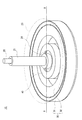
- FIG. 2 is an external perspective view of the motor unit 10.
- the first motor 30 provided in the motor unit 10 is a disk-shaped outer rotor type motor.
- the above-described clutch mechanism 40 is built in a space provided inside the cylindrical first rotor 31 and the first stator 32 of the first motor 30, and the clutch is provided outside the first motor 30. Space saving is achieved as compared with the configuration including the mechanism 40.
- the “cylindrical shape” in the present invention means a shape having a hollow cylindrical portion at least partially including a bottomed cylindrical shape and a cup shape.
- an outer rotor type motor is adopted as the first motor 30 in the present embodiment, but the same effect can be obtained even when the first motor 30 is an inner rotor type motor.
- a bearing 24 is disposed between the inner peripheral surface of the shaft portion of the fixing member 23 (transmission display) and the outer peripheral surface of the cylindrical shaft 21, and smooth rotation of the cylindrical shaft 21 is ensured.
- the distal end portion of the rotating shaft 20 is exposed from the opening of the cylindrical shaft 21, and the rotation of the rotating shaft 20 is transmitted to the pulsator 96 by connecting the exposed portion to the pulsator 96.
- the connecting member 22 shown in FIG. 1 is mounted on the outer peripheral surface of the cylindrical shaft 21, and the rotation of the cylindrical shaft 21 is transmitted to the inner tank 95 a through the connecting member 22.
- the shape of the connecting member 22 can be changed as appropriate according to the shape of the washing and dewatering tub 95 to which the motor unit 10 is applied.
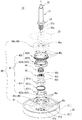
- FIG. 3 is an exploded perspective view of the motor unit 10 and the clutch mechanism 40.
- a disc-shaped first rotating body 41 is fixed to the center of rotation of the first rotor 31 of the first motor 30, and the first rotor 31 is driven to rotate, whereby the first rotating body 41 is driven. Rotates integrally with the first rotor 31.
- the clutch mechanism 40 includes a case 49 including an upper case 49a and a lower case 49b. Inside the case 49, a second rotating body 42 and a second rotating body 42, which are cylindrical members having a flange portion 42d, are provided. A lift mechanism 43 that displaces the second rotary body 42 in the axial direction and a coil spring 44 that constantly urges the second rotating body 42 downward are accommodated.
- the first rotating body 41 and the second rotating body 42 are arranged coaxially on the axis L.
- a clutch tooth portion 41a in which a plurality of protrusions extending toward the second rotating body 42 are arranged at equal intervals in the circumferential direction.
- a clutch tooth portion in which a plurality of protrusions extending toward the first rotating body 41 are arranged at equal intervals in the circumferential direction on the surface of the flange portion 42d of the second rotating body 42 facing the first rotating body 41. 42a is formed.
- a fixed-side tooth portion 45a protruding toward the second rotating body 42 is formed at a portion of the upper case 49a where the second rotating body 42 separated from the first rotating body contacts in the axial direction.
- the fixed side teeth 45a are a plurality of protrusions (protrusions protruding toward the second rotating body 42) arranged at equal intervals in the circumferential direction.
- a fixed-side tooth portion 42c that meshes with the fixed-side tooth portion 45a is formed at a portion of the second rotating body 42 that faces the fixed-side tooth portion 45a.
- the lift mechanism 43 displaces the frame member 431 in the axial direction according to the rotation direction of the second motor 432, the frame member 431 that rotatably supports the second rotating body 42, and the second motor 432.
- the second motor 432 is a stepping motor, and is an inner rotor type motor composed of a cylindrical second rotor 432a and a second stator 432b.
- a second rotating body 42, a frame member 431, and a cam mechanism 433 are arranged inside the second rotor 432a of the second motor 432.
- the second rotor 432a is supported by a roller member 49c included in the case 49 so as to be rotatable in the circumferential direction.
- roller members 49c are provided in the upper case 49a and the lower case 49b, and four roller members 49c are arranged at equal intervals in the circumferential direction. That is, the roller member 49c protrudes in a direction orthogonal to the axial direction at the first contact portion 49c1 that contacts the outer peripheral surface of the second rotor 432a and the end portion in the axial direction, and the axial direction of the second rotor 432a
- a second contact portion 49c2 that contacts the surface is provided.
- the roller member 49c provided in the upper case 49a is provided such that the second contact portion 49c2 is on the upper side in the axial direction.
- the roller member 49c provided in the lower case 49b is provided such that the second contact portion 49c2 is on the lower side in the axial direction.
- the second rotor 432a is rotatable in the circumferential direction by the first contact portion 49c1 of the roller member 49c provided in the upper case 49a and the first contact portion 49c1 of the roller member 49c provided in the lower case 49b. It is supported.
- the second rotor 432a is moved in the axial direction by the second contact portion 49c2 of the roller member 49c provided on the upper case 49a and the second contact portion 49c2 of the roller member 49c provided on the lower case 49b.
- the roller structure 49c having a small contact area and low frictional resistance is used for the bearing structure of the second rotor 432a, whereby the second rotor 432a can be rotated with a smaller force.
- the same effect can be obtained by using a ball member instead of the roller member 49c.
- the frame member 431 is a cylindrical member including an inner peripheral portion 431a that rotatably supports the second rotating body 42 and an outer peripheral portion 431b that supports the inner peripheral portion 431a.
- the outer peripheral portion 431b supports the inner peripheral portion 431a in the axial direction via a coil spring 431c that constantly biases the inner peripheral portion 431a upward, and the inner peripheral portion 431a is at least covered by the elastic deformation of the coil spring 431c. It can be displaced in the axial direction relative to the outer peripheral portion 431b by the height of the fixed side tooth portion 42c.
- the inner peripheral portion 431a is a cylindrical member, and a flange portion 431a1 protruding radially inward is formed on the lower inner peripheral surface of the inner peripheral portion 431a, and the second rotating body 42 is formed by the flange portion 431a1. Supports the axial direction. That is, the lower side in the axial direction of the flange portion 42d of the second rotating body 42 is supported by the flange portion 431a1.
- the case 49 has four fixed shafts 49d erected at equal intervals in the circumferential direction.
- the circumferential direction angle of the outer peripheral portion 431b is fixed by inserting the fixed shaft 49d.
- the inner circumferential portion 431a is fixed in the circumferential direction position by being fitted to the outer circumferential portion 431b.
- the frame member 431 is supported by the case 49 so as not to rotate in the circumferential direction as a whole.
- a spline portion 21 a is provided on the outer peripheral surface of the lower end portion of the cylindrical shaft 21.
- a longitudinal groove corresponding to the protrusion of the spline portion 21a is carved on the inner peripheral surface 42b of the second rotating body 42.
- the cylindrical shaft 21 is inserted into the second rotating body 42, and the inner peripheral surface 42b of the second rotating body 42 and the spline portion 21a mesh with each other, so that the second rotating body 42 is within the range of the spline portion 21a.
- the cylindrical shaft 21 can be slid in the axial direction, and the second rotating body 42 and the cylindrical shaft 21 rotate integrally in the circumferential direction.
- a serration portion 20a is provided on the outer peripheral surface thereof.
- a longitudinal groove corresponding to the protrusion of the serration portion 20a is carved in the bearing 41b of the first rotating body 41.
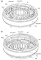
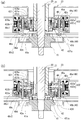
- FIG. 4 and 5 are explanatory views of the lifting and lowering operation of the frame member 431 in the lift mechanism 43.
- FIG. 5 is a cross-sectional view taken along the line AA in FIG.
- the driving force is interrupted by the clutch mechanism 40 by moving the frame member 431 supporting the second rotating body 42 up and down to displace the axial position of the second rotating body 42. This is performed by engaging (joining) and separating (disengaging) the clutch tooth portions 41a and 42a of the first rotating body 41.
- the cam mechanism 433 includes a protrusion 433a that is a cam follower provided on the outer peripheral surface of the frame member 431 (the outer peripheral portion 431b), and an inner peripheral surface of the second rotor 432a into which the protrusion 433a is fitted. And a spiral cam groove 433b.
- a pair of protrusions 433a are provided at symmetrical positions in the circumferential direction of the outer peripheral surface.
- the protrusion 433a in this embodiment is a roller, and the contact resistance between the protrusion 433a and the cam groove 433b is reduced.
- the cam mechanism 433 raises the frame member 431 by rotating the second rotor 432a clockwise as viewed in FIG. 4 (FIGS. 4A and 5A), and the second rotor 432a is viewed in FIG. By rotating counterclockwise, the frame member 431 is lowered (FIGS. 4B and 5B).
- a stepping motor that can rotate in both directions is used as the second motor 432 that is a drive source of the clutch mechanism 40, so that the rotation direction is designated and the clutch mechanism 40 is in a desired state. It is possible to switch directly to
- the rotation angle of the stepping motor can be controlled by the number of steps, it is not necessary to separately provide a mechanism for detecting the raising / lowering state of the frame member 431 and a feedback mechanism for the motor rotation number. Thereby, the number of parts is suppressed and the clutch mechanism 40 is reduced in size. Since the clutch mechanism 40 in the present embodiment is built in the first motor 30, there is a possibility that repair or replacement at the time of failure becomes complicated. Therefore, the failure rate of the clutch mechanism 40 is reduced by using a stepping motor with few contact parts and relatively high reliability, and further reducing the number of parts. Further, the outer shape of the clutch mechanism 40 in the present embodiment is a disk shape, and there is no portion projecting in the radial direction, so that it is suitable for being arranged inside the first rotor 31 and the first stator 32.
- FIG. 4A and 5A show the state of the lift mechanism 43 during the washing operation of the washing machine 90.
- FIG. The clutch mechanism 40 is in a disengaged state during the washing operation.
- the lift mechanism 43 is in a position after the frame member 431 is lifted, and the second rotating body 42 is also lifted by the frame member 431 and separated from the first rotating body 41. . Therefore, the engagement of the clutch tooth portions 41a and 42a of the first rotating body 41 and the second rotating body 42 is in a released state, and the driving force of the first motor 30 is not transmitted to the second rotating body 42 and the subsequent parts. .
- FIG. 4 (b) and 5 (b) show the state of the lift mechanism 43 during the dehydrating operation of the washing machine 90.
- FIG. The clutch mechanism 40 during the dehydrating operation is in the connected state.
- the lift mechanism 43 when the clutch mechanism 40 is in the joint state is in a position where the frame member 431 is lowered, and the second rotating body 42 is also urged downward by the coil spring 44 and is lowered together with the frame member 431.
- the clutch tooth portions 41a and 42a of the first rotating body 41 and the second rotating body 42 are engaged with each other, and the driving force of the first motor 30 is transmitted to the inner tank 95a.
- the driving force of the first motor 30 causes the first rotor 31, the first rotating body 41, the second rotating body 42, the cylindrical shaft 21, and the connection. It is transmitted to the inner tank 95a through the member 22, and the inner tank 95a rotates.
- the pulsator 96 connected to the rotary shaft 20 always rotates together with the first motor 30. That is, the driving force of the first motor 30 is transmitted to the pulsator 96 via the first rotating body 41 and the rotating shaft 20 regardless of the meshing state of the clutch teeth 41a and 42a.
- the washing machine 90 rotates in both cases of the washing operation and the dehydrating operation.
- the clutch mechanism 40 includes a fixed side tooth portion 45 a in the upper case 49 a and a fixed side tooth portion 42 c in the second rotating body 42, and the second rotating body 42 is separated from the first rotating body 41.
- the fixed side tooth portion 45a and the fixed side tooth portion 42c are engaged with each other, whereby the rotation of the second rotating body 42 is engaged with the upper case 49a, and the inner tank 95a is fixed in the circumferential direction.
- the clutch mechanism 40 does not include a mechanism for determining the lifting / lowering state of the frame member 431 and a feedback mechanism for the motor rotation speed, and applies a pulse corresponding to a predetermined step + ⁇ to the second motor 432.
- the step-out of the second motor 432 can be directly connected to the malfunction of the motor unit 10. Further, the force that raises the second rotating body 42 causes stress to the lift mechanism 43, and may cause damage to the lift mechanism 43.
- the outer peripheral portion 431b of the frame member 431 supports the inner peripheral portion 431a in the axial direction via a coil spring 431c.
- the inner peripheral portion 431a can be displaced in the axial direction with respect to the outer peripheral portion 431b by at least the height of the fixed side tooth portion 42c when the coil spring 431c is elastically deformed. Accordingly, even when the apexes of the fixed side tooth portion 45a and the fixed side tooth portion 42c collide with each other, the inner peripheral portion 431a is temporarily displaced downward with respect to the outer peripheral portion 431b, thereby separating the outer peripheral portion 431b. It can be moved to the hour position.
Landscapes
- Engineering & Computer Science (AREA)
- Textile Engineering (AREA)
- Main Body Construction Of Washing Machines And Laundry Dryers (AREA)
- Detail Structures Of Washing Machines And Dryers (AREA)
Abstract
狭小な配置スペースであっても配置可能であり、また、クラッチの継断状態を直接的に切り替えることが可能なクラッチ機構、および、かかるクラッチ機構を内部に収容した洗濯機用モータユニットを提供する。同軸上に配置され互いに係合可能な第一の回転体および第二の回転体と、該第二の回転体と前記第一の回転体との係合・離間を切り替えるリフト機構と、を備え、前記リフト機構は、両方向に回転可能な第二のモータを備え、前記第二のモータは、円筒状の第二のロータおよび第二のステータを備え、前記第二の回転体は、前記第二のロータおよび第二のステータの内側に配置されていることを特徴とするクラッチ機構、および該クラッチ機構を備える洗濯機用モータユニットにより解決する。
Description
本発明はクラッチ機構および該クラッチ機構を備える洗濯機用モータユニットに関する。
下記特許文献1および2には、モータから回転槽への駆動力の伝達を継断するクラッチ機構を備えた洗濯機用モータユニットが開示されている。
特許文献1のクラッチ14を操作するクラッチ作動機構は、スリーブ54を作動レバー66で昇降させて、スリーブ54をロッキングブラケット74と係合・離間させることにより、駆動モータ10から内槽6への駆動力の伝達を継断する。スリーブ54は作動レバー66のフォーク部80に回転可能に支持されており、アクチュエータ65が作動レバー66を揺動させることにより、スリーブ54が上下方向に移動する。
特許文献2のクラッチ機構7は、第2回転体20が回転可能に支持された支持部材34を支持部材移動機構35により昇降させ、第2回転体20を第1回転体13と係合・離間させることにより、モータ5から洗濯漕3への駆動力の伝達を継断する。支持部材34は、支持部材移動機構35の同期モータ37とその減速輪列63により周方向に回動され、さらにカム機構39が作用することにより、第2回転体20とともに上下方向に移動する。
特許文献1のクラッチ機構は、クラッチ14の外部に備えられた作動レバー66を、同じくクラッチ14の外部に備えられたアクチュエータ65により揺動させることから、クラッチ作動機構の取り付けスペースが広く必要となり、また、取り付け作業も煩雑となる。
特許文献2のクラッチ機構7は、特許文献1のクラッチ作動機構よりも小さなスペースで取り付けが可能である。しかし、特許文献2のクラッチ機構7は、一方向にのみ回転する同期モータ37を使用していることから、クラッチの継状態と断状態とをシーケンスに繰り返すほかなく、クラッチの継断状態が不明であるときに、所望の状態に直接的に切り替えることができない。そのため、特許文献2のクラッチ機構7は、タクトスイッチ71を用いた検出機構40や、ホールIC85を用いた洗濯槽回転検出装置8を別途備え、クラッチのその時々の状態を判別しながら継断を制御している。
特許文献2のモータ5は、クラッチ機構7の外部に別体として配置されているが、例えばモータ5をダイレクトドライブモーターとし、内部にクラッチ機構7を収容する構成とする場合、モータ内部の空間がステータなどの部品に割かれることから、クラッチ機構7の配置スペースに対する制約はよりシビアなものとなる。このような狭小な配置スペースにクラッチ機構7を収容する場合には、クラッチ機構7を構成する同期モータ37、減速輪列63、検出機構40、洗濯槽回転検出装置8などのサイズが問題となる。
上記問題に鑑み、本発明が解決しようとする課題は、狭小な配置スペースであっても配置可能であり、また、クラッチの継断状態を直接的に切り替えることが可能なクラッチ機構、および、かかるクラッチ機構を内部に収容した洗濯機用モータユニットを提供することにある。
上記課題を解決するため、本発明のクラッチ機構は、同軸上に配置され互いに係合可能な第一の回転体および第二の回転体と、前記第二の回転体を軸方向に変位させ、該第二の回転体と前記第一の回転体との係合・離間を切り替えるリフト機構と、前記第二の回転体と前記リフト機構とが収容されるケースと、を備え、前記リフト機構は、両方向に回転可能な第二のモータを備え、前記第二のモータは、円筒状の第二のロータおよび第二のステータを備え、前記第二の回転体は、前記第二のロータおよび前記第二のステータの内側に配置されていることを要旨とする。
第二の回転体を、クラッチ機構の駆動源である第二のモータの内部に配置することにより、駆動源の出力を第二の回転体へ伝達する部品点数を最小化することができる。これによりクラッチ機構の小型化が図られるとともに、部品点数が減ることによる信頼性の向上効果が期待される。
また、本発明のクラッチ機構は、前記リフト機構がさらに、前記第二の回転体を回転可能に支持するフレーム部材と、前記第二のモータの回転方向に応じて前記フレーム部材を軸方向に変位させるカム機構と、を備え、前記第二のロータおよび前記第二のステータの内側にさらに、前記フレーム部材および前記カム機構が配置されている構成としても良い。
リフト機構がフレーム部材およびカム機構を備え、これらが第二のロータおよび第二のステータの内側に配置されることにより、クラッチ機構が第二の回転体を軸方向に変位させるために必要な機構のすべてを第二のロータおよび第二のステータの内側に収めることが可能となる。これにより、クラッチ装置の外形を軸方向や径方向への突出部のない円盤状あるいは円柱状にすることができる。
また、本発明のクラッチ機構は、前記第二のモータがステッピングモータであることが望ましい。
ステッピングモータを使用することにより、ステップ数による回転角度の制御が可能となるため、フレーム部材の昇降状態を判別するための機構や、モータ回転数のフィードバック機構を備える必要がなくなり、クラッチ機構の小型化を図ることができる。さらに、ステッピングモータは接触部品が少ないことから信頼性も高い。
また、本発明のクラッチ機構は、前記第二のモータがインナーロータ型モータであり、前記フレーム部材が前記ケースに周方向に回転不能に支持され、前記カム機構が、前記フレーム部材の外周面に設けられたカムフォロアーである突起部と、該突起部が嵌入される、前記第二のロータの内周面に設けられた螺旋状のカム溝と、からなる構成としても良い。
フレーム部材と第二のロータに直接カム機構を設けることにより、別途カム機構を設ける構成に比べて部品点数を抑えることができる。これによりクラッチ機構のさらなる小型化、信頼性の向上を図ることができる。
また、本発明のクラッチ機構は、前記第二のロータが、前記ケースに設けられたローラー部材またはボール部材により周方向に回転可能に支持されることが望ましい。
第二のロータの軸受構造に、接触面積が小さく摩擦抵抗が低いローラー部材またはボール部材を用いることにより、第二のロータをより小さな力で回転させることが可能となる。
また、本発明のクラッチ機構は、前記ケースにおける、前記第一の回転体から離間した前記第二の回転体がその軸方向に接触する部分に、前記第二の回転体側に突出した固定側歯部が形成され、前記第二の回転体における前記固定側歯部と対向する部分に、該固定側歯部と噛合する被固定側歯部が形成され、前記第二の回転体がその離間位置において、前記固定側歯部と前記被固定側歯部とが噛合することにより前記ケースに回転不能に係止され、前記フレーム部材が、前記第二の回転体を支持する内周部と、前記内周部を支持する外周部と、を備える円筒状の部材であり、前記外周部は付勢部材を介して前記内周部を軸方向に支持し、前記内周部は前記付勢部材により、少なくとも前記被固定側歯部の高さ分、前記外周部に対して軸方向に変位可能であることが望ましい。
洗濯機の洗濯動作時においては、摩擦による第二の回転体の連れ回りや洗濯水の水流などによる、回転槽の不必要な回転を防止する必要がある。ケースと第二の回転体が固定側歯部および被固定側歯部を備えることにより、第一の回転体から離間した第二の回転体の回転がケースにより係止され、回転槽が固定される。ここで、固定側歯部と被固定側歯部とが互いに噛合わず、その頂点同士が突き当たった状態となった場合、これら歯部による回転槽の固定効果を得ることができないばかりか、第二の回転体を上昇させる力がリフト機構へのストレスとなり、リフト機構の破損を招くおそれがある。また、第二のモータにステッピングモータを使用している場合は、第二のモータが脱調するおそれもある。フレーム部材の内周部を付勢部材により軸方向に変位可能な構成とすることにより、クラッチの断操作時にこれら歯部の頂点同士が突き当たった場合でも、内周部(および第二の回転体)の上昇を付勢部材により一時的に吸収することで、外周部だけを離間時の軸方向位置に移動させることが可能となる。その後、第二の回転体が周方向に僅かに回転し、上記歯部の頂点同士が突き当たった状態が解消されたときに、内周部は付勢部材の付勢力により本来の位置(固定側歯部側の初期位置)に戻り、上記歯部同士が噛合する。かかる構成とすることにより、クラッチの断操作によるリフト機構の破損を回避できるとともに、回転槽の回転を抑制することができる。
また、本発明の洗濯機用モータユニットは、第一のモータを備え、前記第一のモータは円筒状の第一のロータおよび第一のステータを有し、前記第一のロータおよび前記第一のステータの内側には、請求項1から請求項6のいずれか一項に記載のクラッチ機構が配置され、前記第一の回転体は、前記第一のモータにより回転駆動されることを要旨とする。
本発明のクラッチ装置は上記構成を備えることにより省スペース化を図ることができる。そして第一のモータの内部にクラッチ装置を収容することにより、クラッチ装置の配置スペースをさらに縮小することができるとともに、洗濯機用モータユニットの洗濯機への取り付け作業も簡略化することができる。特に本発明のクラッチ機構の外形は円盤状あるいは円筒状とすることが可能であることから、円筒状の第一のロータおよび第一のステータの内側に配置することに適している。一方、かかる構成においてクラッチ機構が故障した場合、クラッチ機構が第一のモータの内部に収容されていることから、その修理や交換が煩雑となるおそれがある。本発明におけるクラッチ機構は、部品点数が削減され、故障率が抑えられていることから、上記の不利な効果が補われ、配置スペースの縮小という有利な効果が顕著となる。
また、本発明の洗濯機用モータユニットは、前記第一の回転体の回転中心に、該第一の回転体と一体に回転する回転軸が立設され、前記回転軸は、外周面にスプライン部が形成された筒状軸に挿通され、前記回転軸の先端部は前記筒状軸から露出し、前記第二の回転体は、前記スプライン部に嵌合されることにより、該スプライン部の軸方向に移動可能であり、かつ、該筒状軸と周方向に一体に回転し、前記第一の回転体と前記第二の回転体の係合時には、前記第一のモータの駆動力により前記回転軸および前記筒状軸が回転し、前記第一の回転体と前記第二の回転体の離間時には、前記第一のモータの駆動力により前記回転軸のみが回転する構成としても良い。
本発明にかかるクラッチ機構および洗濯機用モータユニットによれば、狭小な配置スペースであっても配置可能であり、また、クラッチの継断状態を直接的に切り替えることが可能なクラッチ機構、および、かかるクラッチ機構を内部に収容した洗濯機用モータユニットを提供することができる。
以下、本発明にかかるクラッチ機構、および該クラッチ機構を備える洗濯機用モータユニットの実施形態について図面を用いて説明する。本実施形態にかかる洗濯機用モータユニットは渦巻式の全自動電気洗濯機に搭載され、クラッチ機構は衣類の洗濯工程に応じて、パルセータのみを回転させる洗濯動作と、パルセータと回転槽の両方を回転させる脱水動作と、を切り替える。尚、本実施形態における「上」、「下」、および「垂直方向」とは図1に示される上下方向をいう。
(全体構成)
図1は本実施形態にかかる全自動電気洗濯機90(以下、単に「洗濯機90」という。)の概略構成を示す断面図である。洗濯機90は上面の開口部に開閉可能なカバー92を備える角筒状の筐体91を有し、筐体91の内部には、洗濯兼脱水槽95を構成する有底筒状の内槽95aおよび外槽95bと、洗濯機用モータユニット10(以下、単に「モータユニット10」という。)が収容されている。外槽95bは、緩衝機構を備える吊り棒93により筐体91に吊り下げられ、その底部には洗濯水を外部に排出する排水パイプ94が連結されている。回転槽である内槽95aは外槽95b内において回転可能に支持され、その底面中央にはパルセータ96が設置されている。
図1は本実施形態にかかる全自動電気洗濯機90(以下、単に「洗濯機90」という。)の概略構成を示す断面図である。洗濯機90は上面の開口部に開閉可能なカバー92を備える角筒状の筐体91を有し、筐体91の内部には、洗濯兼脱水槽95を構成する有底筒状の内槽95aおよび外槽95bと、洗濯機用モータユニット10(以下、単に「モータユニット10」という。)が収容されている。外槽95bは、緩衝機構を備える吊り棒93により筐体91に吊り下げられ、その底部には洗濯水を外部に排出する排水パイプ94が連結されている。回転槽である内槽95aは外槽95b内において回転可能に支持され、その底面中央にはパルセータ96が設置されている。
パルセータ96および内槽95aは、洗濯兼脱水槽95の下方に配置されたモータユニット10に連結されている。モータユニット10の回転軸20は、その先端部が内槽95aの底面を貫通してパルセータ96に接続されており、パルセータ96は回転軸20と一体に回転する。モータユニット10の筒状軸21は、連結部材22を介して内槽95aの下面に連結されており、内槽95aは筒状軸21と一体に回転する。
外槽95bの下面にはモータユニット10の固定部材23が取り付けられている。モータユニット10は第一のモータ30を備え、第一のモータ30の第一のロータ31の内側に、回転軸20、筒状軸21、および後述するクラッチ機構40が配置されている。クラッチ機構40は第一のモータ30から筒状軸21への駆動力の伝達を継断することにより内槽95aの回転を制御する。
洗濯機90の開口部から衣類が投入され、洗濯機90が洗濯動作を開始すると、図示しない給水管を介して洗濯兼脱水槽95に洗濯水が供給される。その後、第一のモータ30により回転軸20およびパルセータ96が回転駆動され、衣類の洗濯が行われる。この間、筒状軸21および内槽95aへの駆動力の伝達はクラッチ機構40により切断されている。
洗濯動作が終了し、洗濯水が外槽95bの排水パイプ94から排出されると、洗濯機90は衣類を脱水する脱水動作に移行する。脱水動作では、第一のモータ30の駆動力はクラッチ機構40により筒状軸21へも伝達され、パルセータ96および内槽95aが一体的に回転する。
(モータユニットの構成)
図2はモータユニット10の外観斜視図である。モータユニット10の備える第一のモータ30は円盤形状のアウターロータ型モータである。第一のモータ30が有する円筒状の第一のロータ31および第一のステータ32の内側に設けられた空間には上述のクラッチ機構40が内蔵されており、第一のモータ30の外部にクラッチ機構40を備える構成に比べて省スペース化が図られている。尚、本発明における「円筒状」とは、有底筒形状やコップ形状を含む、中空の円筒部を少なくとも一部に有する形状を意味している。また、本実施形態における第一のモータ30にはアウターロータ型モータが採用されているが、第一のモータ30をインナーロータ型モータとした場合でも同様の効果を得ることはできる。
図2はモータユニット10の外観斜視図である。モータユニット10の備える第一のモータ30は円盤形状のアウターロータ型モータである。第一のモータ30が有する円筒状の第一のロータ31および第一のステータ32の内側に設けられた空間には上述のクラッチ機構40が内蔵されており、第一のモータ30の外部にクラッチ機構40を備える構成に比べて省スペース化が図られている。尚、本発明における「円筒状」とは、有底筒形状やコップ形状を含む、中空の円筒部を少なくとも一部に有する形状を意味している。また、本実施形態における第一のモータ30にはアウターロータ型モータが採用されているが、第一のモータ30をインナーロータ型モータとした場合でも同様の効果を得ることはできる。
固定部材23(透過表示)の軸部内周面と筒状軸21の外周面との間にはベアリング24が配置され、筒状軸21の円滑な回転が確保されている。回転軸20の先端部は筒状軸21の開口から露出しており、かかる露出部がパルセータ96に接続されることにより、回転軸20の回転がパルセータ96に伝達される。また、筒状軸21の外周面には図1に示す連結部材22が装着され、筒状軸21の回転は連結部材22を介して内槽95aに伝達される。尚、連結部材22の形状はモータユニット10を適用する洗濯兼脱水槽95の形状に応じて適宜変更可能である。
(クラッチ機構の構成)
図3はモータユニット10およびクラッチ機構40の分解斜視図である。第一のモータ30の第一のロータ31の回転中心には円盤形状の第一の回転体41が固定されており、第一のロータ31が回転駆動されることにより、第一の回転体41は第一のロータ31と一体に回転する。
図3はモータユニット10およびクラッチ機構40の分解斜視図である。第一のモータ30の第一のロータ31の回転中心には円盤形状の第一の回転体41が固定されており、第一のロータ31が回転駆動されることにより、第一の回転体41は第一のロータ31と一体に回転する。
クラッチ機構40は、上ケース49aおよび下ケース49bからなるケース49を備え、ケース49の内部には、フランジ部42dを有する円筒状の部材である第二の回転体42、第二の回転体42をその軸方向に変位させるリフト機構43、第二の回転体42を常時下方へ付勢するコイルバネ44が収容されている。
第一の回転体41、第二の回転体42は軸線L上で同軸に配置されている。第一の回転体41における第二の回転体42との対向面には、第二の回転体42側に延びる複数の突条が周方向等間隔に配置されて成るクラッチ歯部41aが形成されている。第二の回転体42のフランジ部42dにおける第一の回転体41との対向面には、第一の回転体41側に延びる複数の突条が周方向等間隔に配置されて成るクラッチ歯部42aが形成されている。また、上ケース49aにおける、第一の回転体から離間した第二の回転体42が軸方向で接触する部分には、第二の回転体42側に突出した固定側歯部45aが形成されている。固定側歯部45aは、周方向等間隔に配置された複数の突条(第二の回転体42側に突出する突起部)である。第二の回転体42における固定側歯部45aと対向する部分には、固定側歯部45aと噛合する被固定側歯部42cが形成されている。
リフト機構43は、第二のモータ432と、第二の回転体42を回転可能に支持するフレーム部材431と、第二のモータ432の回転方向に応じて、フレーム部材431を軸方向に変位させるカム機構433と、からなる。
第二のモータ432はステッピングモータであり、円筒状の第二のロータ432aおよび第二のステータ432bからなるインナーロータ型モータである。第二のモータ432の第二のロータ432aの内側には、第二の回転体42、フレーム部材431、カム機構433が配置されている。
第二のロータ432aは、ケース49の備えるローラー部材49cにより周方向に回転可能に支持されている。ローラー部材49cは、上ケース49aおよび下ケース49bに設けられ、それぞれ周方向等間隔に4つ配置されている。つまり、ローラー部材49cは、第二のロータ432aの外周面と接触する第1接触部49c1、および、軸方向における端部において軸方向と直交する方向に突出し、第二のロータ432aの軸方向の面と接触する第2接触部49c2を備えている。上ケース49aに設けられたローラー部材49cは、第2接触部49c2が軸方向上側となるように設けられている。下ケース49bに設けられたローラー部材49cは、第2接触部49c2が軸方向下側となるように設けられている。第二のロータ432aは、上ケース49aに設けられたローラー部材49cの第1接触部49c1、および、下ケース49bに設けられたローラー部材49cの第1接触部49c1によって、周方向に回転可能に支持されている。また、第二のロータ432aは、上ケース49aに設けられたローラー部材49cの第2接触部49c2、および、下ケース49bに設けられたローラー部材49cの第2接触部49c2によって、軸方向への移動を規制されている。第二のロータ432aの軸受構造に、接触面積が小さく摩擦抵抗が低いローラー部材49cが用いられていることにより、第二のロータ432aをより小さな力で回転させることが可能とされている。尚、ローラー部材49cに代えてボール部材を用いても同様の効果を得ることができる。
フレーム部材431は、第二の回転体42を回転可能に支持する内周部431aと、内周部431aを支持する外周部431bと、を備える円筒状の部材である。外周部431bは、内周部431aを常時上方へ付勢するコイルバネ431cを介して内周部431aを軸方向に支持しており、コイルバネ431cが弾性変形することにより内周部431aは、少なくとも被固定側歯部42cの高さ分、外周部431bに対して軸方向に変位可能とされている。内周部431aは、筒状部材であって、内周部431aの下側の内周面には、径方向内側に突出した鍔部431a1が形成され、鍔部431a1によって第二の回転体42の軸方向を支持している。つまり、第二の回転体42のフランジ部42dの軸方向下側が、鍔部431a1によって支持されている。
ケース49はその内部に、周方向等間隔に立設された4つの固定軸49dを有している。外周部431bは、固定軸49dが挿通されることによりその周方向角度が固定されている。また、内周部431aは、外周部431bに嵌合されることにより周方向位置が固定されている。これにより、フレーム部材431は全体として周方向に回転不能にケース49に支持される。
筒状軸21の下端部には、その外周面にスプライン部21aが設けられている。第二の回転体42の内周面42bには、スプライン部21aの突条に対応する縦溝が刻まれている。筒状軸21が第二の回転体42に挿通され、第二の回転体42の内周面42bとスプライン部21aとが噛合することにより、第二の回転体42はスプライン部21aの範囲において筒状軸21を軸方向に摺動でき、また、第二の回転体42と筒状軸21とが周方向に一体に回転するようになる。
回転軸20の下端近傍部には、その外周面にセレーション部20aが設けられている。第一の回転体41の軸受41bには、セレーション部20aの突条に対応する縦溝が刻まれている。セレーション部20aが軸受41bに挿通され、セレーション部20aと軸受41bとが噛合することにより、第一の回転体41と回転軸20とは周方向に一体に回転する。
(リフト機構の動作)
図4および図5はリフト機構43におけるフレーム部材431の昇降動作の説明図である。尚、図4においてフレーム部材431の外周部431bは透過表示されている。図5は図2のA-A位置における断面図である。クラッチ機構40による駆動力の継断は、第二の回転体42を支持するフレーム部材431を昇降させることにより、第二の回転体42の軸方向位置を変位させ、第二の回転体42と第一の回転体41のクラッチ歯部41a、42aを係合(継状態)および離間(断状態)させることにより行う。
図4および図5はリフト機構43におけるフレーム部材431の昇降動作の説明図である。尚、図4においてフレーム部材431の外周部431bは透過表示されている。図5は図2のA-A位置における断面図である。クラッチ機構40による駆動力の継断は、第二の回転体42を支持するフレーム部材431を昇降させることにより、第二の回転体42の軸方向位置を変位させ、第二の回転体42と第一の回転体41のクラッチ歯部41a、42aを係合(継状態)および離間(断状態)させることにより行う。
本実施形態におけるカム機構433は、フレーム部材431(外周部431b)の外周面に設けられたカムフォロアーである突起部433aと、突起部433aが嵌入される、第二のロータ432aの内周面に設けられた螺旋状のカム溝433bと、から構成されている。尚、突起部433aは、かかる外周面の周方向における対称位置に一対設けられている。本実施形態における突起部433aはローラーとなっており、突起部433aとカム溝433bとの接触抵抗が低減されている。
カム機構433は、第二のロータ432aが図4視時計回りに回転することによりフレーム部材431を上昇させ(図4(a)、図5(a))、第二のロータ432aが図4視反時計回りに回転することによりフレーム部材431を下降させる(図4(b)、図5(b))。
本実施形態においては、クラッチ機構40の駆動源である第二のモータ432として、両方向に回転可能なステッピングモータが用いられていることにより、その回転方向を指定してクラッチ機構40を所望の状態に直接的に切り替えることが可能とされている。
また、ステッピングモータは、ステップ数により回転角度を制御可能であることから、フレーム部材431の昇降状態を検知するための機構や、モータ回転数のフィードバック機構を別途備える必要がない。これにより部品点数が抑えられ、クラッチ機構40の小型化が図られている。本実施形態におけるクラッチ機構40は第一のモータ30に内蔵されている関係上、故障時の修理や交換が煩雑となるおそれがある。そのため、接触部品が少なく比較的信頼性の高いステッピングモータを用い、さらに部品点数を削減することによりクラッチ機構40の故障率を低減している。また、本実施形態におけるクラッチ機構40の外形は円盤形状であり、径方向に突出した部分がないことから、第一のロータ31および第一のステータ32の内側に配置するのに好適である。
図4(a)および図5(a)は、洗濯機90の洗濯動作時におけるリフト機構43の状態を示している。洗濯動作時におけるクラッチ機構40は断状態にある。クラッチ機構40が断状態のときのリフト機構43は、フレーム部材431が上昇後の位置にあり、第二の回転体42もフレーム部材431により持ち上げられ、第一の回転体41から離間している。よって、第一の回転体41と第二の回転体42のクラッチ歯部41a、42aの噛合は解除状態にあり、第一のモータ30の駆動力は第二の回転体42以降へは伝達されない。
図4(b)および図5(b)は、洗濯機90の脱水動作時におけるリフト機構43の状態を示している。脱水動作時におけるクラッチ機構40は継状態にある。クラッチ機構40が継状態のときのリフト機構43は、フレーム部材431が下降した位置にあり、第二の回転体42もコイルバネ44により下方に付勢され、フレーム部材431とともに下降している。これにより、第一の回転体41と第二の回転体42のクラッチ歯部41a、42aが噛合し、第一のモータ30の駆動力が内槽95aへ伝達される。つまり、クラッチ歯部41a、42aが噛合することにより、第一のモータ30の駆動力は、第一のロータ31、第一の回転体41、第二の回転体42、筒状軸21、連結部材22を介して内槽95aへと伝達され、内槽95aが回転する。
尚、回転軸20は第一の回転体41に固定され、第一の回転体41と一体に回転することから、回転軸20に接続されたパルセータ96は、常に第一のモータ30とともに回転する。すなわち、第一のモータ30の駆動力は、クラッチ歯部41a、42aの噛合状態にかかわらず、第一の回転体41、回転軸20を介してパルセータ96に伝達されることから、パルセータ96は洗濯機90の洗濯動作および脱水動作のいずれの場合においても回転する。
(洗濯動作時における内槽固定構造)
以下、図5を用いて洗濯動作時における内槽固定構造について説明する。洗濯機90の洗濯動作時(クラッチ機構40を断状態としたとき)は、摩擦による第二の回転体42の連れ回りや洗濯水の水流などにより内槽95aが回転してしまうことを防止する必要がある。そのため、クラッチ機構40は、上ケース49aに固定側歯部45aを、第二の回転体42に被固定側歯部42cを備えており、第二の回転体42が第一の回転体41から離間したときには、固定側歯部45aと被固定側歯部42cとを噛合させることにより、上ケース49aに第二の回転体42の回転を係止させ、内槽95aを周方向に固定する。
以下、図5を用いて洗濯動作時における内槽固定構造について説明する。洗濯機90の洗濯動作時(クラッチ機構40を断状態としたとき)は、摩擦による第二の回転体42の連れ回りや洗濯水の水流などにより内槽95aが回転してしまうことを防止する必要がある。そのため、クラッチ機構40は、上ケース49aに固定側歯部45aを、第二の回転体42に被固定側歯部42cを備えており、第二の回転体42が第一の回転体41から離間したときには、固定側歯部45aと被固定側歯部42cとを噛合させることにより、上ケース49aに第二の回転体42の回転を係止させ、内槽95aを周方向に固定する。
ここで、固定側歯部45aと被固定側歯部42cとが互いに噛合わず、その頂点同士が突き当たった状態となった場合、内槽95aの固定効果を得ることができないばかりか、フレーム部材431が上昇できず第二のモータ432が脱調を起こすおそれがある。特に本実施形態のクラッチ機構40は、フレーム部材431の昇降状態を判別するための機構や、モータ回転数のフィードバック機構を備えておらず、第二のモータ432に所定ステップ+α分のパルスを与えることでクラッチの継断操作が完遂されたものと判断していることから、第二のモータ432の脱調がモータユニット10の動作不良に直結し得る。さらに、第二の回転体42を上昇させる力がリフト機構43へのストレスとなり、リフト機構43の破損を招くおそれもある。
本実施形態におけるフレーム部材431の外周部431bは、コイルバネ431cを介して内周部431aを軸方向に支持している。上で述べたように、内周部431aはコイルバネ431cが弾性変形することにより少なくとも被固定側歯部42cの高さ分、外周部431bに対して軸方向に変位可能とされている。これにより、固定側歯部45aおよび被固定側歯部42cの頂点同士が突き当たった場合でも、内周部431aが外周部431bに対して一時的に下方に変位することで、外周部431bを離間時の位置まで移動させることができる。その後、第二の回転体42が周方向に僅かに回転し、固定側歯部45aおよび被固定側歯部42cの頂点同士が突き当たった状態が解消したときに、内周部431aはコイルバネ431cの付勢力により上方(固定側歯部45a側の初期位置)に戻り、固定側歯部45aと被固定側歯部42cとが噛合する。上記構成とすることにより、クラッチ機構40を断状態としたときの第二のモータ432の脱調やリフト機構43の破損を回避できるとともに、内槽95aの回転を抑制することが可能とされている。
以上、本発明の実施の形態について詳細に説明したが、本発明は上記実施の形態に何ら限定されるものではなく、本発明の要旨を逸脱しない範囲で種々の改変が可能である。
10 モータユニット
20 回転軸
21 筒状軸
30 第一のモータ
31 第一のロータ
32 第一のステータ
40 クラッチ機構
41 第一の回転体
41b 軸受
42 第二の回転体
42b 内周面
42c 被固定側歯部
43 リフト機構
431 フレーム部材
431a 内周部
431b 外周部
431c コイルバネ
432 第二のモータ
432a 第二のロータ
432b 第二のステータ
433 カム機構
433a 突起部
433b カム溝
44 コイルバネ
45a 固定側歯部
49 ケース
49a 上ケース
49b 下ケース
49c ローラー部材
49d 固定軸
20 回転軸
21 筒状軸
30 第一のモータ
31 第一のロータ
32 第一のステータ
40 クラッチ機構
41 第一の回転体
41b 軸受
42 第二の回転体
42b 内周面
42c 被固定側歯部
43 リフト機構
431 フレーム部材
431a 内周部
431b 外周部
431c コイルバネ
432 第二のモータ
432a 第二のロータ
432b 第二のステータ
433 カム機構
433a 突起部
433b カム溝
44 コイルバネ
45a 固定側歯部
49 ケース
49a 上ケース
49b 下ケース
49c ローラー部材
49d 固定軸
Claims (8)
- 同軸上に配置され互いに係合可能な第一の回転体および第二の回転体と、
前記第二の回転体を軸方向に変位させ、該第二の回転体と前記第一の回転体との係合・離間を切り替えるリフト機構と、
前記第二の回転体と前記リフト機構とが収容されるケースと、を備え、
前記リフト機構は、両方向に回転可能な第二のモータを備え、
前記第二のモータは、円筒状の第二のロータおよび第二のステータを備え、
前記第二の回転体は、前記第二のロータおよび前記第二のステータの内側に配置されていることを特徴とするクラッチ機構。 - 前記リフト機構はさらに、
前記第二の回転体を回転可能に支持するフレーム部材と、
前記第二のモータの回転方向に応じて前記フレーム部材を軸方向に変位させるカム機構と、を備え、
前記第二のロータおよび前記第二のステータの内側にはさらに、前記フレーム部材および前記カム機構が配置されていることを特徴とする請求項1に記載のクラッチ機構。 - 前記第二のモータはステッピングモータであることを特徴とする請求項1または請求項2に記載のクラッチ機構。
- 前記第二のモータはインナーロータ型モータであり、
前記フレーム部材は前記ケースに周方向に回転不能に支持され、
前記カム機構は、前記フレーム部材の外周面に設けられたカムフォロアーである突起部と、該突起部が嵌入される、前記第二のロータの内周面に設けられた螺旋状のカム溝と、からなることを特徴とする請求項2または請求項3に記載のクラッチ機構。 - 前記第二のロータは、前記ケースに設けられたローラー部材またはボール部材により周方向に回転可能に支持されることを特徴とする請求項1から請求項4のいずれか一項に記載のクラッチ機構。
- 前記ケースにおける、前記第一の回転体から離間した前記第二の回転体がその軸方向で接触する部分には、前記第二の回転体側に突出した固定側歯部が形成され、
前記第二の回転体における前記固定側歯部と対向する部分には、該固定側歯部と噛合する被固定側歯部が形成され、
前記第二の回転体はその離間位置において、前記固定側歯部と前記被固定側歯部とが噛合することにより前記ケースに回転不能に係止され、
前記フレーム部材は、
前記第二の回転体を支持する内周部と、
前記内周部を支持する外周部と、を備える円筒状の部材であり、
前記外周部は付勢部材を介して前記内周部を軸方向に支持し、
前記内周部は前記付勢部材により、少なくとも前記被固定側歯部の高さ分、前記外周部に対して軸方向に変位可能であることを特徴とする請求項2から請求項5のいずれか一項に記載のクラッチ機構。 - 第一のモータを備え、
前記第一のモータは円筒状の第一のロータおよび第一のステータを有し、
前記第一のロータおよび前記第一のステータの内側には、請求項1から請求項6のいずれか一項に記載のクラッチ機構が配置され、
前記第一の回転体は、前記第一のモータにより回転駆動されることを特徴とする洗濯機用モータユニット。 - 前記第一の回転体の回転中心には、該第一の回転体と一体に回転する回転軸が立設され、
前記回転軸は、外周面にスプライン部が形成された筒状軸に挿通され、
前記回転軸の先端部は前記筒状軸から露出し、
前記第二の回転体は、前記スプライン部に嵌合されることにより、該スプライン部の軸方向に移動可能であり、かつ、該筒状軸と周方向に一体に回転し、
前記第一の回転体と前記第二の回転体の係合時には、前記第一のモータの駆動力により前記回転軸および前記筒状軸が回転し、
前記第一の回転体と前記第二の回転体の離間時には、前記第一のモータの駆動力により前記回転軸のみが回転することを特徴とする請求項7に記載の洗濯機用モータユニット。
Applications Claiming Priority (2)
| Application Number | Priority Date | Filing Date | Title |
|---|---|---|---|
| JP2015059355A JP6446305B2 (ja) | 2015-03-23 | 2015-03-23 | クラッチ機構および洗濯機用モータユニット |
| JP2015-059355 | 2015-03-23 |
Publications (1)
| Publication Number | Publication Date |
|---|---|
| WO2016152859A1 true WO2016152859A1 (ja) | 2016-09-29 |
Family
ID=56978882
Family Applications (1)
| Application Number | Title | Priority Date | Filing Date |
|---|---|---|---|
| PCT/JP2016/058996 Ceased WO2016152859A1 (ja) | 2015-03-23 | 2016-03-22 | クラッチ機構および洗濯機用モータユニット |
Country Status (2)
| Country | Link |
|---|---|
| JP (1) | JP6446305B2 (ja) |
| WO (1) | WO2016152859A1 (ja) |
Cited By (1)
| Publication number | Priority date | Publication date | Assignee | Title |
|---|---|---|---|---|
| CN114990852A (zh) * | 2022-03-21 | 2022-09-02 | 刘富豪 | 一种减速器及一种双动力波轮洗衣机 |
Families Citing this family (1)
| Publication number | Priority date | Publication date | Assignee | Title |
|---|---|---|---|---|
| CN112144239B (zh) * | 2019-06-27 | 2022-12-09 | 青岛海尔洗衣机有限公司 | 一种洗衣机减速离合装置 |
Citations (4)
| Publication number | Priority date | Publication date | Assignee | Title |
|---|---|---|---|---|
| JP2001190889A (ja) * | 2000-01-12 | 2001-07-17 | Matsushita Electric Ind Co Ltd | 洗濯機 |
| JP2001204989A (ja) * | 2000-01-28 | 2001-07-31 | Matsushita Electric Ind Co Ltd | 洗濯機 |
| WO2008143528A1 (en) * | 2007-05-18 | 2008-11-27 | Fisher & Paykel Appliances Limited | Laundry machine with lost motion clutch |
| US20120137738A1 (en) * | 2010-12-02 | 2012-06-07 | Kyubum Lee | Washing machine |
Family Cites Families (2)
| Publication number | Priority date | Publication date | Assignee | Title |
|---|---|---|---|---|
| AU777010B2 (en) * | 2002-01-17 | 2004-09-30 | Lg Electronics Inc. | Direct-drive washing machine |
| JP5940423B2 (ja) * | 2012-09-28 | 2016-06-29 | 日本電産サンキョー株式会社 | 洗濯機のクラッチ機構および洗濯機 |
-
2015
- 2015-03-23 JP JP2015059355A patent/JP6446305B2/ja not_active Expired - Fee Related
-
2016
- 2016-03-22 WO PCT/JP2016/058996 patent/WO2016152859A1/ja not_active Ceased
Patent Citations (4)
| Publication number | Priority date | Publication date | Assignee | Title |
|---|---|---|---|---|
| JP2001190889A (ja) * | 2000-01-12 | 2001-07-17 | Matsushita Electric Ind Co Ltd | 洗濯機 |
| JP2001204989A (ja) * | 2000-01-28 | 2001-07-31 | Matsushita Electric Ind Co Ltd | 洗濯機 |
| WO2008143528A1 (en) * | 2007-05-18 | 2008-11-27 | Fisher & Paykel Appliances Limited | Laundry machine with lost motion clutch |
| US20120137738A1 (en) * | 2010-12-02 | 2012-06-07 | Kyubum Lee | Washing machine |
Cited By (2)
| Publication number | Priority date | Publication date | Assignee | Title |
|---|---|---|---|---|
| CN114990852A (zh) * | 2022-03-21 | 2022-09-02 | 刘富豪 | 一种减速器及一种双动力波轮洗衣机 |
| CN114990852B (zh) * | 2022-03-21 | 2023-09-29 | 刘富豪 | 一种减速器及一种双动力波轮洗衣机 |
Also Published As
| Publication number | Publication date |
|---|---|
| JP6446305B2 (ja) | 2018-12-26 |
| JP2016174877A (ja) | 2016-10-06 |
Similar Documents
| Publication | Publication Date | Title |
|---|---|---|
| CN108474167B (zh) | 洗衣机的离合器组合件 | |
| KR20150022842A (ko) | 세탁기 드라이버 | |
| EP2889417B1 (en) | Power transmission apparatus and power control apparatus for a washing machine | |
| CN107075773B (zh) | 滚筒洗衣机 | |
| KR20170093917A (ko) | 세탁 기계 드라이버 | |
| CN108796956A (zh) | 一种多洗涤模式可切换的洗衣机 | |
| JP6446305B2 (ja) | クラッチ機構および洗濯機用モータユニット | |
| WO2015131482A1 (zh) | 滚筒洗衣机 | |
| KR102163318B1 (ko) | 세탁기 | |
| JP6454568B2 (ja) | クラッチ機構および洗濯機用モータユニット | |
| JP6553374B2 (ja) | 洗濯機用モータユニット | |
| EP3599306B1 (en) | Washing machine | |
| CN106460281A (zh) | 滚筒式洗衣机 | |
| KR102123430B1 (ko) | 세탁기 | |
| CN110835827B (zh) | 顶开式双动力洗衣机 | |
| KR102300789B1 (ko) | 세탁기 | |
| KR102036225B1 (ko) | 세탁기 | |
| KR19990084883A (ko) | 세탁기 | |
| KR102045005B1 (ko) | 세탁기 | |
| KR102101731B1 (ko) | 세탁기 | |
| KR102364625B1 (ko) | 세탁기 | |
| JP2019168007A (ja) | 係合装置 | |
| CN110714293B (zh) | 波轮洗衣机 | |
| JP2009165237A (ja) | ギヤードモータ | |
| CN105280409A (zh) | 用于双电源自动转换开关的离合装置 |
Legal Events
| Date | Code | Title | Description |
|---|---|---|---|
| 121 | Ep: the epo has been informed by wipo that ep was designated in this application |
Ref document number: 16768762 Country of ref document: EP Kind code of ref document: A1 |
|
| NENP | Non-entry into the national phase |
Ref country code: DE |
|
| 122 | Ep: pct application non-entry in european phase |
Ref document number: 16768762 Country of ref document: EP Kind code of ref document: A1 |