WO2016152508A1 - 転写媒体 - Google Patents
転写媒体 Download PDFInfo
- Publication number
- WO2016152508A1 WO2016152508A1 PCT/JP2016/057220 JP2016057220W WO2016152508A1 WO 2016152508 A1 WO2016152508 A1 WO 2016152508A1 JP 2016057220 W JP2016057220 W JP 2016057220W WO 2016152508 A1 WO2016152508 A1 WO 2016152508A1
- Authority
- WO
- WIPO (PCT)
- Prior art keywords
- transfer
- hologram
- layer
- transfer medium
- transferred
- Prior art date
- Legal status (The legal status is an assumption and is not a legal conclusion. Google has not performed a legal analysis and makes no representation as to the accuracy of the status listed.)
- Ceased
Links
Images



Classifications
-
- B—PERFORMING OPERATIONS; TRANSPORTING
- B42—BOOKBINDING; ALBUMS; FILES; SPECIAL PRINTED MATTER
- B42D—BOOKS; BOOK COVERS; LOOSE LEAVES; PRINTED MATTER CHARACTERISED BY IDENTIFICATION OR SECURITY FEATURES; PRINTED MATTER OF SPECIAL FORMAT OR STYLE NOT OTHERWISE PROVIDED FOR; DEVICES FOR USE THEREWITH AND NOT OTHERWISE PROVIDED FOR; MOVABLE-STRIP WRITING OR READING APPARATUS
- B42D25/00—Information-bearing cards or sheet-like structures characterised by identification or security features; Manufacture thereof
- B42D25/30—Identification or security features, e.g. for preventing forgery
- B42D25/328—Diffraction gratings; Holograms
-
- B—PERFORMING OPERATIONS; TRANSPORTING
- B42—BOOKBINDING; ALBUMS; FILES; SPECIAL PRINTED MATTER
- B42D—BOOKS; BOOK COVERS; LOOSE LEAVES; PRINTED MATTER CHARACTERISED BY IDENTIFICATION OR SECURITY FEATURES; PRINTED MATTER OF SPECIAL FORMAT OR STYLE NOT OTHERWISE PROVIDED FOR; DEVICES FOR USE THEREWITH AND NOT OTHERWISE PROVIDED FOR; MOVABLE-STRIP WRITING OR READING APPARATUS
- B42D25/00—Information-bearing cards or sheet-like structures characterised by identification or security features; Manufacture thereof
- B42D25/40—Manufacture
-
- G—PHYSICS
- G03—PHOTOGRAPHY; CINEMATOGRAPHY; ANALOGOUS TECHNIQUES USING WAVES OTHER THAN OPTICAL WAVES; ELECTROGRAPHY; HOLOGRAPHY
- G03H—HOLOGRAPHIC PROCESSES OR APPARATUS
- G03H1/00—Holographic processes or apparatus using light, infrared or ultraviolet waves for obtaining holograms or for obtaining an image from them; Details peculiar thereto
- G03H1/02—Details of features involved during the holographic process; Replication of holograms without interference recording
-
- G—PHYSICS
- G03—PHOTOGRAPHY; CINEMATOGRAPHY; ANALOGOUS TECHNIQUES USING WAVES OTHER THAN OPTICAL WAVES; ELECTROGRAPHY; HOLOGRAPHY
- G03H—HOLOGRAPHIC PROCESSES OR APPARATUS
- G03H1/00—Holographic processes or apparatus using light, infrared or ultraviolet waves for obtaining holograms or for obtaining an image from them; Details peculiar thereto
- G03H1/22—Processes or apparatus for obtaining an optical image from holograms
- G03H1/2249—Holobject properties
Definitions
- the present invention relates to a patch type transfer medium having a hologram and a method of transferring a hologram layer.
- the principle of the hologram is that the wavefront of the object light is recorded as interference fringes on the photosensitive material by interfering two light beams (the object light and the reference light) having the same wavelength, and the same wavelength as the reference light at the interference fringe recording When the light of the above is applied, the interference fringes cause a diffraction phenomenon, and the same wavefront as the original object light can be reproduced.
- Such holograms can be classified into several types according to the recording form of interference fringes, but can typically be divided into surface relief holograms and volume holograms.
- a hologram is recorded by forming a fine concavo-convex pattern on the surface of the hologram forming layer.
- the volume hologram a hologram is recorded by three-dimensionally drawing interference fringes generated by light interference as stripes having different refractive indexes in the thickness direction. Since a volume hologram is a hologram image recorded by the difference in refractive index of the material, it is particularly difficult to reproduce as compared with a surface relief hologram. Therefore, the use as a means for preventing forgery of securities and cards is expected.
- a hologram as a design property imparting means or a forgery preventing means
- various methods are known as a method of imparting a hologram to a securities, a card or the like depending on an object to which the hologram is to be imparted.
- a method of inserting a slit hologram or a method of embedding the hologram in a medium so as to be visible from the outside is known, but in general, the hologram is placed at a predetermined position. The method of sticking is used.
- the transfer medium has, for example, a structure in which a hologram layer in which a hologram is recorded on a substrate and an adhesive layer having thermal adhesiveness are sequentially laminated, and the hologram layer is transferred to a transfer target through the adhesive layer.
- a transfer medium a foil type in which a hologram layer and an adhesive layer are formed on the entire surface of a substrate (see, for example, Patent Document 1), and a hologram layer and an adhesive layer are formed in advance in a predetermined shape on the substrate Patch types (see, for example, Patent Documents 2 to 6).
- patch type transfer medium since the hologram layer is formed in a predetermined shape in advance, the generation of burrs at the time of transfer can be reduced, and the transferability can be improved.
- foil type transfer media require a heat press using a mold to transfer the hologram layer in a predetermined shape
- patch type transfer media use a roll laminator or the like for transfer. It also has the advantage of being able to reduce the size and cost of the transfer device.
- an alignment mark is formed which serves as a reference for determining the position at which the hologram layer is transferred to the transfer target.
- alignment marks are usually formed on a substrate (see, for example, Patent Documents 1 and 2).
- the alignment mark is also referred to as a timing mark.
- a printing method is known as a method of forming alignment marks.
- a problem that positional deviation between the alignment marks and the hologram image occurs due to expansion and contraction due to heat and tension in the process after forming alignment marks. There is.
- the alignment mark is formed on the surface of the base opposite to the surface on which the hologram layer is formed, the alignment mark is partially formed. As it is formed, when the long transfer medium is wound in a roll, the thickness of the portion of the alignment mark is cumulatively increased, which causes the surface pressure of only that portion to increase. There is a problem that so-called blocking occurs in which the adhesive layer overlapped in a superimposed manner and the substrate or the alignment mark are in close contact with each other. Then, when such blocking occurs, when the long transfer medium is unwound from the roll, it becomes difficult to unroll smoothly, and the hologram layer or the adhesive layer is peeled off from the base material depending on the degree of adhesion. There is also the problem of In addition, when there is a step due to the alignment mark, there is a problem in manufacturing, for example, when the long transfer medium is rolled up in a roll, the roll is broken.
- a method of performing alignment by detecting a step due to a transfer portion in which a hologram layer and an adhesive layer are formed in a predetermined shape on a base material.
- a step due to the transfer portion since there is a step due to the transfer portion, as in the above case, there is a problem that blocking or winding collapse occurs.
- the present invention has been made in view of the above problems, and can accurately transfer a transfer portion of a transfer medium to a predetermined position of a transfer target, and can suppress the occurrence of blocking and winding collapse.
- the main purpose is to provide a transfer medium.
- the present invention is formed on the above-mentioned exfoliation resin layer of the above-mentioned above-mentioned supporting material which has the supporting substrate and the exfoliating resin layer formed on the above-mentioned supporting substrate.
- a transfer material having a transparent substrate, a hologram layer formed on the transparent substrate, and an adhesive layer formed on the hologram layer, the transfer material being formed in a pattern on the support material
- the transfer material is formed on the support material and has a transfer portion to be transferred to a transfer target, and a non-transfer portion to be formed on the support material and not transfer the transfer material to the transfer target.
- a transfer medium characterized by
- the non-transferred portion since the non-transferred portion has a hologram layer, it can function as an alignment mark. Furthermore, since the non-transfer portion can be formed simultaneously with the transfer portion, positional deviation of the transfer portion and the alignment mark can be suppressed. Therefore, transfer accuracy can be improved. Further, in the present invention, by disposing the transfer portion and the non-transfer portion on the same surface of the support material, it is possible to reduce the step due to the alignment mark and the step due to the transfer portion. Therefore, when the transfer medium of the present invention is long and the long transfer medium is wound in a roll, the surface pressure can be dispersed, and the occurrence of blocking and winding collapse can be suppressed. it can. Further, in the present invention, since it is not necessary to separately perform the process of forming the alignment mark, the manufacturing process can be simplified.
- the transfer medium be long and that the long transfer medium be wound in a roll.
- the long transfer medium is wound in a roll, as described above, the occurrence of blocking and winding collapse can be suppressed, so the present invention is useful for the long transfer medium. is there.
- the present invention is a long transfer medium, and is formed on a support material and a support material having a peelable resin layer formed on the support substrate, and the peelable resin layer of the support material.
- a transfer material having a transparent substrate, a hologram layer formed on the transparent substrate, and an adhesive layer formed on the hologram layer, and the transfer material in the form of a pattern on the support material.
- the first transfer material pattern disposed at the center in the width direction of the support material and the first transfer material pattern are formed at the width direction end of the support material.
- a second transfer material pattern disposed, wherein the first transfer material pattern and the second transfer material pattern have the same layer configuration along the stacking direction.
- the transfer medium is a first transfer material pattern and the second transfer material. It becomes easy to use the pattern as a transfer portion and a non-transfer portion, respectively.
- the transfer medium can suppress the occurrence of blocking and winding collapse.
- the present invention provides a hologram layer transfer method comprising a transfer step of transferring at least a part of the transfer material of the transfer medium to a transfer target using the transfer medium described above.
- the transfer step uses the transfer medium described above, it is possible to transfer the patterned hologram layer with high positional accuracy.
- the above method can reduce the occurrence of blocking and winding collapse during transfer.
- the present invention it is possible to accurately transfer the transfer portion to a predetermined position of the transfer target, and to suppress the occurrence of blocking and winding collapse.
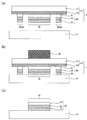
- FIG. 1 is a schematic plan view and a cross-sectional view showing an example of a transfer medium of the present invention. It is process drawing which shows an example of the transcription
- FIG. 6 is a schematic cross-sectional view showing another example of the transfer medium of the present invention.
- FIG. 6 is a schematic plan view showing another example of the transfer medium of the present invention.
- FIG. 5 is a schematic plan view and a cross-sectional view showing another example of the transfer medium of the present invention.
- the transfer medium of the present invention comprises a support substrate, a support material having a release resin layer formed on the support substrate, a transparent substrate formed on the release resin layer of the support material, And a transfer material having a hologram layer formed on a transparent substrate and an adhesive layer formed on the hologram layer, wherein the transfer material is formed in a pattern on the support material, and the support
- the transfer material is formed on a material, and has a transfer portion to be transferred to a transfer target, and a non-transfer portion to be formed on the support material and having the transfer material not to be transferred to a transfer target. It is.
- FIG. 1 (a) is a schematic plan view showing an example of the transfer medium of the present invention
- FIG. 1 (b) is a sectional view taken along the line AA of FIG. 1 (a).
- the transfer medium 1 includes a support material 10 in which a peelable resin layer 12 is formed on a support base 11, a hologram layer 22 on a transparent base 21, and the like.
- the transfer material 20 is formed in a pattern on the peelable resin layer 12 of the support material 10, and the transfer material 20 is formed on the support material 10.
- the non-transfer portion 26 is configured of a portion 26a in which the hologram is recorded and a portion 26b disposed around the portion 26a in which the hologram is not recorded.
- FIGS. 1 (a) and 1 (b) are process drawings showing an example of the transfer method of the transfer medium of the present invention, which is an example using the transfer medium shown in FIGS. 1 (a) and 1 (b).
- FIG. 2A the surface on the adhesive layer 23 side of the transfer medium 1 is made to face the transfer target body 31.
- the non-transfer portion 26 since the non-transfer portion 26 has the hologram layer 22 and can function as the alignment mark M, the non-transfer portion 26 is used as the alignment mark M, and the transfer medium 1 is used based on the alignment mark M. And the alignment of the transferred object 31 is performed.
- FIG. 2A the surface on the adhesive layer 23 side of the transfer medium 1 is made to face the transfer target body 31.
- the non-transfer portion 26 has the hologram layer 22 and can function as the alignment mark M
- the non-transfer portion 26 is used as the alignment mark M
- the transfer medium 1 is used based on the alignment mark M.
- the alignment of the transferred object 31 is performed.
- the transfer medium 1 and the transfer target body 31 are brought into close contact, and the area of the transfer portion 25 of the transfer medium 1 is heated and pressed by the hot stamp 35 from the support material 10 side. Then, the transfer portion 25 of the transfer medium 1 and the transfer receiving body 31 are adhered. Next, by peeling off the support material 10 of the transfer medium 1, the transfer portion 25 is transferred to the transfer receiving body 31 as illustrated in FIG. 2C.
- the non-transferred portion has the transfer layer and the non-transferred portion on which the transfer material is formed on the support material, and the non-transferred portion has the hologram layer and functions as an alignment mark. It is possible to accurately transfer the transfer portion to a predetermined position of the transfer target with reference to the alignment mark which is the transfer portion. Furthermore, since the non-transfer portion can be formed simultaneously with the transfer portion, positional deviation between the transfer portion and the non-transfer portion, that is, positional deviation between the transfer portion and the alignment mark can be suppressed, and transfer accuracy can be improved. Can.
- the non-transfer portion not only has a function as an alignment mark, but the transfer medium of the present invention is long, and when the long transfer medium is rolled up, Also, it can have a function as a spacer for holding a space. That is, by disposing the transfer portion and the non-transfer portion on the same surface of the support material, it is possible to reduce the step due to the alignment mark and the step due to the transfer portion. Therefore, when the long transfer medium of the present invention is rolled up in a roll, the surface pressure increases only at the alignment mark portion or the surface pressure increases only at the transfer portion portion. It is possible to suppress and disperse the surface pressure.
- the transfer portion can be smoothly transferred to the transfer target.
- the transfer portion and the non-transfer portion can be simultaneously formed, and there is no need to separately perform the step of forming the alignment mark, so that the manufacturing process of the transfer medium of the present invention can be simplified. .
- the transfer material in the present invention comprises a transparent substrate formed on the releasable resin layer of the support material, a hologram layer formed on the transparent substrate, and an adhesive layer formed on the hologram layer. And are formed in a pattern on the support material.
- a transparent substrate formed on the releasable resin layer of the support material
- a hologram layer formed on the transparent substrate
- an adhesive layer formed on the hologram layer. And are formed in a pattern on the support material.
- the hologram layer in the present invention is formed on a transparent substrate.
- the hologram layer is one on which a hologram is recorded, and is transferred to a transfer target.
- the hologram layer is not particularly limited as long as the hologram is recorded, and a hologram layer in which a predetermined type of hologram is recorded can be used according to the application of the transfer medium of the present invention, etc. .
- a volume hologram layer in which a volume hologram is recorded or a relief hologram layer in which a surface relief hologram is recorded can be used.
- the material constituting the volume hologram layer is not particularly limited as long as it can record a volume hologram, and materials generally used for volume holograms can be arbitrarily used. Examples of such materials include known volume hologram recording materials such as silver salt materials, gelatin dichromate emulsions, photopolymerizable resins, and photocrosslinkable resins.
- a binder resin a photopolymerizable compound, a first photosensitive material containing a photopolymerization initiator and a sensitizing dye, or (ii) a cationically polymerizable compound, a radically polymerizable compound, photoradical polymerization initiation
- a second photosensitive material containing an agent system and a cationic photopolymerization initiator system can be suitably used.
- the first photosensitive material and the second photosensitive material include those described in JP-A-2013-068960 and JP-A-2009-274428.
- the thickness of the volume hologram layer is not particularly limited as long as it can form a predetermined volume hologram, and is appropriately adjusted according to the type of material. Among them, the thickness of the volume hologram layer is preferably in the range of 1 ⁇ m to 50 ⁇ m, and more preferably in the range of 3 ⁇ m to 25 ⁇ m.
- a relief hologram layer As a relief hologram layer, a general one can be used as a hologram layer on which a surface relief type hologram is recorded.
- a relief hologram layer for example, a hologram original image is exposed to a photoresist to produce a relief surface in a concavo-convex shape, and using this as an original plate, a mold obtained by applying nickel plating to the relief surface is synthesized. What formed the uneven
- the material of the relief hologram layer, the method of forming the relief hologram layer, and the like are disclosed, for example, in Japanese Patent No. 5304018, Japanese Patent No. 5407292, Japanese Patent Laid-Open No. 2010-120201, The ones described can be applied.
- the thickness of the relief hologram layer is not particularly limited as long as it can form a predetermined surface relief hologram, and can be set, for example, in the range of 1 ⁇ m to 10 ⁇ m, and more preferably 2 ⁇ m to 5 ⁇ m. It is preferable to be within the range.
- the adhesive layer in the present invention is formed on the above-mentioned hologram layer.
- the material of the adhesive layer is not particularly limited as long as it can bond the transfer portion and the transferred body when transferring the transferred portion to the transferred body using the transfer medium of the present invention. However, it is appropriately selected in accordance with the material etc. of the material to be transferred.
- a heat-sensitive adhesive which melts or softens by heating to exert an adhesive effect can be preferably used.
- the heat sensitive adhesive include vinyl chloride resins, vinyl acetate resins, vinyl chloride vinyl acetate copolymer resins, acrylic resins, polyester resins and the like.
- the adhesive layer may contain an additive as needed.
- a method of forming an adhesive layer a method of applying and drying a composition for an adhesive layer in which the above-mentioned thermal adhesive is dissolved or dispersed in a solvent may be mentioned.
- a coating method for example, a common coating method such as roll coating, gravure coating, comma coating, etc. can be used.
- the thickness of the adhesive layer can be, for example, about 1 ⁇ m to 30 ⁇ m, and is appropriately adjusted in accordance with the application of the transfer medium of the present invention, the type of a transfer target, and the like.
- the thickness of the adhesive layer is preferably in the range of 1 ⁇ m to 15 ⁇ m, and preferably 3 ⁇ m or more on the image forming surface.
- the thickness of the adhesive layer is in the range of 5 ⁇ m to 30 ⁇ m. It is preferably present, and more preferably in the range of 20 ⁇ m to 30 ⁇ m.
- the transparent base material in the present invention has a function of covering the surface of the hologram layer and protecting the hologram layer when the transfer portion is transferred to a transfer target using the transfer medium of the present invention. It is.
- the transparent substrate is not particularly limited as long as it has durability such as weather resistance, abrasion resistance, chemical resistance and the like in addition to transparency, and various materials can be used according to the application of the transfer medium of the present invention.
- the following materials can be used.
- polyester resins such as polyethylene terephthalate, polyethylene naphthalate, etc.
- polyamide resins vinyl resins such as polyvinyl chloride
- engineering resins such as acrylic resins, imide resins, polyarylates, polycarbonates, cyclic polyolefin resins, cellulose
- copolymer resin which has such resin as a main component, and a mixture (an alloy is included) may be sufficient.
- the transparent substrate may be a single layer, or may be a laminate of a plurality of layers.
- triacetyl cellulose film is preferable because it has excellent optical properties.
- the transparent substrate may be a stretched film or an unstretched film, but is preferably a film stretched in a uniaxial direction or a biaxial direction for the purpose of improving the strength.
- a biaxially stretched polyethylene terephthalate film is suitable because of its good heat resistance and mechanical strength.
- the surface of the transparent substrate on the hologram layer side may be subjected to an adhesion treatment such as corona discharge treatment, plasma treatment, primer (also referred to as anchor coating, adhesion promoter, or adhesive) coating treatment, alkali treatment, etc. Good.
- an adhesion treatment such as corona discharge treatment, plasma treatment, primer (also referred to as anchor coating, adhesion promoter, or adhesive) coating treatment, alkali treatment, etc. Good.
- the transparent base material may contain additives such as a filler, a plasticizer, a colorant, and an antistatic agent, as necessary.
- the thickness of the transparent substrate is, for example, about 2.5 ⁇ m to 50 ⁇ m, and preferably in the range of 2.5 ⁇ m to 25 ⁇ m.
- a primer layer 24 may be formed between the hologram layer 22 and the adhesive layer 23 as illustrated in FIG. 3 in order to improve adhesion.
- materials for the primer layer include polyester resins, polyacrylate resins, polyvinyl acetate resins, polyurethane resins, polyamide resins, polyethylene resins, and polypropylene resins.
- a method of forming a primer layer a method of applying and drying a composition for primer layer in which the above-mentioned material is dissolved or dispersed in a solvent may be mentioned.
- the coating method include gravure coating, gravure reverse coating, roll coating, comma coating, die coating and the like.
- the transfer material in the present invention is formed in a pattern on the support material.
- the pattern shape of the transfer material is appropriately selected according to the shapes of a transfer portion and a non-transfer portion described later.
- the transfer material in the form of a pattern hereinafter, may be referred to as a transfer material pattern
- the first transfer material is disposed at the center in the width direction of the support material.
- the second transfer material pattern disposed at the widthwise end of the support material from the first transfer material pattern.
- the width direction can be a direction orthogonal to the longitudinal direction.
- Examples of the first transfer material pattern disposed at the center in the width direction and the second transfer material pattern disposed at the widthwise end of the support material from the first transfer material pattern include, for example, FIG.
- a band-like region (second region 52) parallel to the longitudinal direction of the transfer medium 10, which can include all of the second transfer material pattern 42 is a first A band-like region (first region 51) parallel to the longitudinal direction of the transfer medium 10 that can include all of the transfer material pattern 41 is positioned on the width direction end side of the support material 10 without overlapping in plan view It can be FIGS.
- 4A and 4B are schematic plan views showing an example of the transfer medium of the present invention, in which the second region 52 is disposed at the widthwise end of the support member 10 from the first region 51, An example in which the area 51 and the second area 52 are arranged so that their end portions do not contact with each other is shown.
- 4A and 4B show an example in which the first transfer material pattern 41 is used as the transfer portion 25 and the second transfer material pattern 42 is used as the non-transfer portion 26. is there.
- FIGS. 4A and 4B an example in which the first region 51 includes the center in the width direction of the plain support member 10 is shown. Furthermore, in FIG.
- FIG. 4A shows an example in which one second transfer material pattern 42 is placed on the first transfer material pattern 41 in a position where the two transfer material patterns 41 are disposed to face each other across the transfer material pattern 41. An example is shown in which only one widthwise end is disposed.
- the first transfer material pattern 41 and the second transfer material pattern 42 are disposed at the same interval in the longitudinal direction of the transfer medium 10, and the first transfer material pattern 41 is obtained.
- the second transfer material pattern 42 is disposed to overlap in the width direction.
- the first transfer material pattern and the second transfer material pattern may have different layer configurations along the stacking direction, but have the same layer configuration along the stacking direction. Is preferred. This is because the formation of the first transfer material pattern and the second transfer material pattern is easy, and it is easy to make the same thickness. Therefore, the transfer medium can suppress the occurrence of blocking and winding collapse.
- having the same layer configuration as each other along the stacking direction means that the first transfer material pattern and the second transfer material pattern are formed simultaneously, for example, a layer And the stacking order may be the same.
- having the same type of layer can mean that the constituent material, the thickness, and the like are the same.
- the layer type can be included if the constituent materials are the same. More specifically, the hologram layers of the first transfer material pattern and the second transfer material pattern are recorded in separate steps in order to make the holograms recorded by the respective transfer material patterns different. Even when recording is performed using two types of original plates having different asperities, if the constituent material and thickness are the same, they are included in the same type of hologram layer.
- a half cut process As a method of forming the transfer material in a pattern on the support material, for example, a half cut process can be used.
- the half-cut method is not particularly limited as long as it is a method capable of half-cutting a transfer material, and for example, a laminate in which a support material and a transfer material are laminated between an upper mold attached with a cutter blade and a pedestal A method of inserting a body and moving the upper mold up and down, a cylinder type rotary cutter method, a heat treatment method by laser processing means, and the like can be mentioned. After half cutting, the portions other than the transfer portion and the non-transfer portion are peeled off in advance.
- the transfer part is a part on which the transfer material is formed on the support material and transferred to the transfer target, and the transfer material is formed on the support material on the non-transfer part. It is a portion which is not transferred to a transferee.
- the non-transferred portion has a function as an alignment mark, and the alignment mark is a position at which the transferred portion is transferred to the transferred body when the transferred portion is transferred to the transferred body using the transfer medium of the present invention. It becomes the standard to decide the
- the transfer part and the non-transfer part it is possible to transfer the transfer part to the transferred body and not transfer the non-transfer part to the transferred body, and to make the non-transfer part function as an alignment mark.
- the arrangement is not particularly limited as long as the arrangement is possible, and it is sufficient that the non-transferred part is not arranged in the area to be heated when transferring the transfer body of the transfer medium to the transfer target body, ie, the transfer area.
- the non-transferred portion is preferably arranged in the vicinity of the transferred portion other than the transfer region.
- one non-transfer portion 26 may be disposed for one transfer portion 25, and is illustrated in FIGS. 1A and 1B.
- a plurality of non-transfer parts 26 may be arranged for one transfer part 25.
- two non-transfer parts 26 are disposed for one transfer part 25, and two non-transfer parts 26 are one transfer part 25.
- position in the position which mutually opposes on both sides is preferable to arrange
- the non-transfer portion 26 may be composed of a portion 26a where the hologram is recorded and a portion 26b which is disposed around the portion and where the hologram is not recorded. . This is because both the portion 26a in which the hologram is recorded and the portion 26b in which the hologram is not recorded can function as a spacer.
- FIG. 5 (a) is a schematic plan view showing another example of the transfer medium of the present invention
- FIG. 5 (b) is a sectional view taken along the line AA of FIG. 5 (a).
- the arrangement of the non-transferred portion relative to the support is not particularly limited.
- the end of the support 10 The non-transferred portion 26 may be disposed at the center of the support member, although not shown.
- FIG. 1A when the non-transferred portions 26 are disposed at both ends of the support member 10, the non-transferred portions are disposed so as to be symmetrical with respect to the transferred portion. It is preferable for dispersion.
- the transfer portion can be transferred continuously, as shown in FIGS. 1 (a), (b) and FIGS. 5 (a), (b).
- a plurality of non-transfer parts 26 be arranged at predetermined intervals on a straight line parallel to the longitudinal direction of the support material 10. This arrangement makes it easy to continuously determine the transfer position of the transfer portion.
- the shape of the transfer portion is not particularly limited, and may be any shape such as, for example, a polygon such as a triangle or a quadrangle, a circle, an ellipse, or a donut shape.
- the size of the transfer portion may be larger or smaller than the size of the transfer surface of the transfer body. Also, the transfer portion may have a partially missing portion.
- the shape of the non-transfer portion is not particularly limited as long as it can function as an alignment mark, and may be any shape such as a cross, a polygon such as triangle or quadrilateral, a circle, or an ellipse, for example. be able to.
- the size of the non-transfer portion is not particularly limited as long as it can function as an alignment mark, but the transfer medium of the present invention is long, and the long transfer medium is rolled. In the case of winding, it is preferable to have a size that can function as a spacer.
- the area of the non-transferred portion be within the range of 5 to 80% of the transferred portion. If the area of the non-transferred portion is too small, the dispersion effect of the surface pressure can not be obtained sufficiently, and depending on the size of the transferred portion, the non-transferred portion becomes a margin when removing the margin after half cutting. At the same time, it may be easy to peel off. In addition, when the area of the non-transferred portion is too large, the number of non-transferred areas increases, and the manufacturing cost becomes high.
- the reproduction angle of the hologram recorded in the hologram layer of the transfer part and the reproduction angle of the hologram recorded in the hologram layer of the non-transfer part may be the same or different. Among them, it is preferable that the reproduction angle of the hologram be different between the transfer portion and the non-transfer portion.
- the transferred part may be used as the alignment mark depending on the arrangement of the transferred part and the non-transferred part.
- a method of making the reproduction angle of the hologram different between the transfer portion and the non-transfer portion it is appropriately selected according to the type of the hologram.
- a volume hologram layer for example, a method of recording volume holograms separately in a separate step on a volume hologram layer constituting a transfer portion and a volume hologram layer constituting a non-transfer portion, and two different volume holograms were recorded.
- the method of using an original version is mentioned.
- a relief hologram layer for example, a method using two types of original plates having different concavo-convex shapes, and a method using an original plate having two types of different concavo-convex shapes are mentioned.
- the hologram may be recorded on the entire surface of the hologram layer, or the hologram may be recorded on a part of the hologram layer. If a hologram is recorded in at least a part of the hologram layer of the non-transferred portion, the portion where the hologram is recorded can function as an alignment mark. Further, in the non-transferred portion, both the portion where the hologram is recorded and the portion where the hologram is not recorded can function as a spacer.
- Support Material in the present invention has a support base and a peelable resin layer formed on the support base.
- each structure in a support material is demonstrated.
- the support base material in the present invention supports the above-mentioned transfer material.
- the support substrate is not particularly limited, and examples thereof include, but are not limited to, condenser paper, glassine paper, sulfuric acid paper, or high-size paper, synthetic paper (polyolefin-based or polystyrene-based), high-quality paper, coated paper, synthetic resin or Emulsion impregnated paper, or polyester resin such as polyethylene terephthalate, polybutylene terephthalate, polyethylene naphthalate etc., polyamide resin, vinyl resin such as polyvinyl chloride, engineering resin such as acrylic resin, imide resin, polyarylate, etc.
- Films of polycarbonate, cyclic polyolefin resin, cellulose resin and the like can be used.
- the corona discharge treatment may be given to the surface at the side of the peelable resin layer of a support base material, and a primer layer may be formed.
- the supporting substrate may be a sheet or a long sheet, but is preferably long. This is because the transfer base can be continuously transferred to the transfer target by using a long transfer medium, which has a long support base. In addition, when the long transfer medium is wound in a roll, as described above, the occurrence of blocking and winding collapse can be suppressed.
- the thickness of the supporting substrate is preferably in the range of 10 ⁇ m to 100 ⁇ m. If the supporting substrate is too thin, the transfer medium of the present invention loses its so-called stiffness, and may not be transported by the transfer device, or curls or wrinkles may occur in the transfer medium of the present invention. On the other hand, if the supporting substrate is too thick, the transfer medium of the present invention becomes too thick, and the force for conveying and driving in the transfer device becomes too large, and there is a risk that the transfer device may fail or can not be conveyed normally. is there.
- the peelable resin layer in the present invention is formed on the above-mentioned support base material.
- the releasable resin layer is not particularly limited as long as the transfer portion can be releasable from the releasable resin layer surface, and, for example, a pressure-sensitive adhesive layer, a simple adhesive layer, an extrusion coating (EC) Layers and the like can be used.
- Examples of the pressure-sensitive adhesive used in the pressure-sensitive adhesive layer include general solvent-based and water-based pressure-sensitive adhesives.
- examples thereof include polymers, ethylene-vinyl acetate copolymers, polyurethane resins, and rubber resins such as natural rubber and chloroprene rubber.
- the adhesive strength of the pressure-sensitive adhesive layer is preferably within the range of 5 g to 1,000 g in the peeling method according to JIS Z0237 based on the peel strength between the transparent substrate and the pressure-sensitive adhesive layer. The above-mentioned peel strength can be adjusted by the kind, coating amount, etc. of an adhesive.
- coating said adhesive and drying is mentioned.
- the coating method include general coating methods such as gravure coating, roll coating, and comma coating.
- the coating amount of the pressure-sensitive adhesive is generally about 3 g / m 2 to 30 g / m 2 or so in solid content, and is appropriately selected according to the target peel strength.
- dry lamination, hot melt lamination, etc. of an adhesive layer can be applied as a lamination method. .
- Materials used for the simple adhesive layer include, for example, styrene-butadiene copolymer rubber (SBR), acrylonitrile-butadiene copolymer rubber (NBR), latex of acrylic resin such as polyacrylate, rubber-based resin, waxes, A mixture of them is mentioned.
- SBR styrene-butadiene copolymer rubber
- NBR acrylonitrile-butadiene copolymer rubber
- latex of acrylic resin such as polyacrylate
- rubber-based resin rubber-based resin
- waxes waxes
- a primer layer may be formed between the support substrate and the simple adhesive layer.
- the thermoplastic resin used for the extrusion coating (EC) layer is not particularly limited as long as it is a resin which does not adhere essentially to the transparent substrate and has EC processing characteristics, but among them, it is generally used as the transparent substrate
- the polyolefin resin which does not have intrinsic adhesiveness with respect to the PET film used for and which is excellent also in processability is preferable.
- LDPE, MDPE, HDPE, PP resin and the like can be mentioned.
- a mat roll is used as a cooling roll for EC processing of these resins, and the mat surface is transferred to the surface of the EC layer to shape the concavo-convex shape and make it opaque.
- Polyolefin resin such as calcium carbonate, titanium oxide, etc.
- the white pigment of the above may be mixed and made opaque.
- the EC layer may be a single layer, or may be a laminate of multiple layers.
- the peel strength between the transparent substrate and the EC layer can be adjusted by the processing temperature at EC processing and the type of resin.
- the transfer medium of the present invention may be sheet-like or long, and preferably long. By using a long transfer medium, it is possible to transfer the transfer portion to the transfer target body continuously.
- the elongated transfer medium is wound in a roll, as described above, since the occurrence of blocking and winding collapse can be suppressed, the present invention is applied to the elongated transfer medium. It is useful.
- the transfer medium of the present invention may be transferred to a transfer target by any method such as a thermal transfer method, for example, a hot stamp (foil stamping) by heat imprint, transfer by a heat roll, a thermal head (heat sensitive print head).
- a thermal transfer method for example, a hot stamp (foil stamping) by heat imprint, transfer by a heat roll, a thermal head (heat sensitive print head).
- a general method such as a thermal printer (also referred to as a thermal transfer printer) can be applied.
- the image may be heated and transferred in accordance with the shape of the transfer portion.
- the material to be transferred is not particularly limited.
- natural fiber paper, coated paper, tracing paper, plastic film which does not deform due to heat during transfer, glass, metal, ceramics, wood, cloth, etc. may be used.
- an image, coloring, printing, and other decorations may be given to a to-be-transferred body.
- Applications of the transfer medium of the present invention include anti-counterfeiting applications, such as banknotes, stock certificates, securities, certificates, gift certificates, checks, bills, admission tickets, passbooks, gift certificates, tickets, betting tickets, aviation Ticket, stamp, stamp, appreciation ticket, admission card, pass card, ticket such as cash voucher, cash card, credit card, ID card, prepaid card, members' card, IC card, optical card, point card etc., greeting cards , Postcards, business cards, driver's licenses, employee ID cards, membership cards, admission cards, various certificates such as passports and their identification photos, cartons, cases, packaging materials such as soft packaging materials, bags, cosmetics, watches, Brand accessories such as lighters, envelopes, tags, bookmarks, calendars, posters, brochures, name plates, stationery for report papers, etc., radios, te It can be used for electric appliances such as levy, calculator, office automation equipment, music software, video software, computer software, recording materials such as game software, building materials, panels, emblems, keys, cloths, clothes
- the method of transferring a hologram layer of the present invention is characterized by including a transfer step of transferring at least a part of the transfer material of the transfer medium to a transfer target using the transfer medium described above. It is
- a hologram layer transfer method may be the same as that shown in FIG. 2 described above.
- the transfer step uses the transfer medium described above, it is possible to transfer the patterned hologram layer with high positional accuracy.
- the above method can reduce the occurrence of blocking and winding collapse during transfer.
- a method of transferring at least a part of the transfer material of the transfer medium to the transfer target using the above-described transfer medium in the transfer step among the transfer materials of the pattern form included in the transfer medium, for example, a method capable of accurately transferring only the transfer material in a pattern form to be transferred to the transfer target, that is, only the transfer portion to the transfer target can be used. For example, “5. The contents described in the section “Method” can be used.
- the transfer method depending on the application of the transfer body used in the transfer method of the present invention, for example, even a method of transferring all of the transfer materials in the pattern form contained in the transfer medium to the transfer body Good.
- the application of the transfer medium, the transfer-receiving body and the transfer-receiving body to which the pattern-like transfer material is transferred can be the same as the contents described in the section "A. Transfer medium" above, The description here is omitted.
- the present invention is not limited to the above embodiment.
- the above-described embodiment is an exemplification, and the present invention has the substantially same constitution as the technical idea described in the claims of the present invention, and the same effects can be exhibited by any invention. It is included in the technical scope of
- Example 1 (Production of first laminate) 50 m of PET film (Lumirror T60 (50 ⁇ m) Toray Industries, Ltd.) is prepared as a first film, and a volume hologram recording material having the following composition is gravure coated as a hologram forming material to a dry film thickness of 7 ⁇ m. The entire surface was coated, and an easy adhesion treated PET film (A4300 (38 .mu.m) made by TOYOBO) was laminated on the coated surface as a transparent base 21 to prepare a first laminate.
- A4300 38 .mu.m
- TOYOBO easy adhesion treated PET film
- volume type hologram was photographed and recorded on the laminate of the first film / volume hologram layer 22 / transparent substrate 21 using a laser beam with a wavelength of 532 nm. After recording, the laminate is heated in an atmosphere at 100 ° C. for 10 minutes, and ultraviolet rays with an irradiation dose of 2500 mJ / cm 2 are applied to the entire surface using a high pressure mercury lamp to fix the layer of volume hologram recording material. The In addition, the pattern of the hologram was recorded so that the desired hologram pattern was disposed at the transfer portion 25 (a circle with a diameter of 20 mm) after half cutting.
- the alignment mark is disposed in the non-transfer part.
- a mirror hologram (5 mm ⁇ 5 mm square) 26 (M) was recorded.
- a PET film (Lumirror 50T60, manufactured by Toray Industries, Inc.) is laminated by a dry lamination method using a two-component curable urethane adhesive as the releasable resin layer 12 of the second laminate and the support base 11.
- the 3rd laminated body which consists of layer composition of support base material 11 / (urethane system adhesive layer) / peelable resin layer 12 / transparent base material 21 / hologram layer 22 / 1st film was obtained.
- An upper mold was prepared in which a circular rectangular cutter blade with a diameter of 20 mm and a rectangular cutter blade for the non-transfer unit 26 were arranged at a distance of 3 mm for the transfer unit 25.
- the shape of the cutter blade for the non-transfer portion 26 is a square of 5 mm ⁇ 10 mm, and two pieces are disposed so as to be symmetrical with respect to the transfer portion 25 as shown in FIG.
- a half cut process was performed on the laminate for the transfer medium 1 by a press method of the prepared upper mold and a pedestal, and portions other than the transfer portion 25 and the non-transfer portion 26 were removed.
- Example 2 As shown in FIG. 5, a transfer medium 1 was produced in the same manner as in Example 1 except that the alignment hologram marks were arranged in one non-transfer part 26 with respect to the transfer part 25.
- the transfer part, the non-transfer part, the size of the hologram mark, and the distance between the transfer part and the transfer part were the same as in Example 1.
- Example 3 A transfer medium 1 was produced in the same manner as in Example 1 except that the alignment hologram mark was a square of 2 mm ⁇ 2 mm, and the size of the non-transfer portion 26 was a square of 3 mm ⁇ 3 mm.
- Comparative Example 1 A transfer medium 1 was produced in the same manner as in Example 1 except that the non-transfer portion 26 was not provided.
- the winding pressure applied at the time of slit winding is dispersed to the transfer portion 25 and the non-transfer portion 26, so that a stable continuous winding transfer medium 1 can be obtained. Further, in the transfer test, the transfer portion 25 of the transfer medium 1 was transferred to the PVC card, and the non-transfer portion 26 remained on the transfer medium 1. Further, in the third embodiment, since the area of the transfer portion 25 is relatively large with respect to the non-transfer portion 26 in the slit winding, a large amount of winding pressure is applied to the transfer portion 25 and the transfer portion 25 is wound. Although the phenomenon in which the roll diameter of the portion where it was made becomes smaller than the roll diameter of the other was seen, winding was possible. In the first comparative example, in the slit winding, a large amount of winding pressure is applied to the transfer portion 25, and the roll end may be wound while fluttering at the time of the slit winding, which may cause a winding collapse.
Landscapes
- Physics & Mathematics (AREA)
- General Physics & Mathematics (AREA)
- Engineering & Computer Science (AREA)
- Manufacturing & Machinery (AREA)
- Credit Cards Or The Like (AREA)
- Holo Graphy (AREA)
- Laminated Bodies (AREA)
- Decoration By Transfer Pictures (AREA)
Abstract
本発明は、転写媒体の転写部を被転写体の所定の位置に精度良く転写し、かつ、ブロッキングや巻き崩れの発生を抑制することが可能な転写媒体を提供することを主目的とする。 本発明は、支持基材、および上記支持基材上に形成された剥離性樹脂層を有する支持材と、上記支持材の上記剥離性樹脂層上に形成された透明基材、上記透明基材上に形成されたホログラム層、および上記ホログラム層上に形成された接着層を有する転写材とを有し、上記支持材上に上記転写材がパターン状に形成されており、上記支持材上に上記転写材が形成され、被転写体に転写する転写部と、上記支持材上に上記転写材が形成され、被転写体に転写しない非転写部とを有することを特徴とする転写媒体を提供することにより、上記課題を解決する。
Description
本発明は、ホログラムを有するパッチタイプの転写媒体およびホログラム層の転写方法に関するものである。
現在、クレジットカードやキャッシュカード等に代表されるプラスチックカードにおいては、主として複製防止および意匠性付与の観点からホログラム付カードが広く用いられるに至っている。ホログラムは、その優れた立体表現や美しさに加えて、複製が困難であるという利点を有することからセキュリティ用途等に多く使用されている。
ホログラムの原理は、波長の等しい二つの光(物体光と参照光)を干渉させることによって、物体光の波面が干渉縞として感光材料に記録されており、干渉縞記録時の参照光と同一波長の光が当てられると干渉縞によって回折現象が生じ、元の物体光と同一の波面が再生できるというものである。
ホログラムの原理は、波長の等しい二つの光(物体光と参照光)を干渉させることによって、物体光の波面が干渉縞として感光材料に記録されており、干渉縞記録時の参照光と同一波長の光が当てられると干渉縞によって回折現象が生じ、元の物体光と同一の波面が再生できるというものである。
このようなホログラムは、干渉縞の記録形態によっていくつかの種類に分類することができるが、代表的には表面レリーフ型ホログラムと体積ホログラムとに分けることができる。ここで、表面レリーフ型ホログラムは、ホログラム形成層の表面に微細な凹凸パターンが賦型されることによりホログラムが記録されたものである。一方、体積ホログラムは光の干渉によって生じる干渉縞が、屈折率の異なる縞として厚み方向に三次元的に描画されることによってホログラムが記録されたものである。体積ホログラムは材料の屈折率差によってホログラム像が記録されたものであるため、表面レリーフ型ホログラムに比べて複製することが特に困難である。したがって、有価証券やカード類の偽造防止手段としての用途が期待されている。
また、意匠性の付与や偽造防止手段等としてホログラムを用いる場合において、ホログラムを有価証券やカード等に付与する方法としては、ホログラムを付与する対象に応じて種々の方法が知られている。このような方法としては、例えば、スリット状のホログラムをすき込む方法や、ホログラムを外部から視認可能なように媒体中に埋め込む方法が知られているが、一般的にはホログラムを所定の位置に貼付する方法が用いられている。中でも、より簡便な方法として、任意の基材上に転写媒体からホログラム層を転写することによってホログラム層を所定の位置に貼付する方法が広く用いられるに至っている。
また、ホログラムを用いた意匠性の付与や偽造防止は、その有用性に鑑みさらなる汎用性の向上が求められている。これに伴い、工業的生産過程において連続的にホログラムを所定の位置に付与することを可能にするため、長尺状の転写媒体を用いて、ホログラムを連続的に転写する方法も開発されている。
また、ホログラムを用いた意匠性の付与や偽造防止は、その有用性に鑑みさらなる汎用性の向上が求められている。これに伴い、工業的生産過程において連続的にホログラムを所定の位置に付与することを可能にするため、長尺状の転写媒体を用いて、ホログラムを連続的に転写する方法も開発されている。
転写媒体は、例えば基材上にホログラムが記録されたホログラム層と熱接着性を有する接着層とが順に積層された構成を有するものであり、接着層を介して被転写体にホログラム層を転写させる。
転写媒体としては、基材上にホログラム層および接着層が全面に形成されているフォイルタイプ(例えば特許文献1参照)、および、基材上に予めホログラム層および接着層が所定の形状に形成されているパッチタイプ(例えば特許文献2~6参照)等がある。パッチタイプの転写媒体では、予め所定の形状にホログラム層が形成されているため、転写時のバリの発生を低減することができ、転写性を向上させることができる。また、フォイルタイプの転写媒体では、ホログラム層を所定の形状で転写するためには、金型を用いた熱プレスが必要であるのに対し、パッチタイプの転写媒体では、ロールラミネータ等で転写することもでき、転写装置の小型化、低コスト化につながるという利点もある。
転写媒体としては、基材上にホログラム層および接着層が全面に形成されているフォイルタイプ(例えば特許文献1参照)、および、基材上に予めホログラム層および接着層が所定の形状に形成されているパッチタイプ(例えば特許文献2~6参照)等がある。パッチタイプの転写媒体では、予め所定の形状にホログラム層が形成されているため、転写時のバリの発生を低減することができ、転写性を向上させることができる。また、フォイルタイプの転写媒体では、ホログラム層を所定の形状で転写するためには、金型を用いた熱プレスが必要であるのに対し、パッチタイプの転写媒体では、ロールラミネータ等で転写することもでき、転写装置の小型化、低コスト化につながるという利点もある。
パッチタイプの転写媒体においては、ホログラム層を被転写体に転写する位置を決定する基準となる位置合わせマークが形成されることが一般的である。このような位置合わせマークは基材上に形成されるのが通常である(例えば特許文献1、2参照)。なお、位置合わせマークは、タイミングマークとも称される。
位置合わせマークの形成方法としては例えば印刷法が知られており、この場合、位置合わせマーク形成後の工程での熱や張力による伸縮によって、位置合わせマークとホログラム像との位置ずれが生じるという問題がある。また、位置合わせマークを形成する工程を別途行う必要がある。
また、長尺状の転写媒体を用いる場合において、基材のホログラム層が形成されている面とは反対側の面に位置合わせマークが形成されている場合には、位置合わせマークが部分的に形成されているため、長尺状の転写媒体をロール状に巻き取ると、位置合わせマークの部分の厚みが累積的に増加し、これに起因してその部分のみの面圧が増加してしまい、重畳的に重なり合った接着層と基材または位置合わせマークとが密着してしまう、いわゆるブロッキングが生じるという問題がある。そして、このようなブロッキングが生じると、長尺状の転写媒体をロールから巻き出す際に、円滑に巻き出すことが困難になり、さらに密着の程度によってはホログラム層や接着層が基材から剥離してしまうという問題もある。また、位置合わせマークによる段差があると、長尺状の転写媒体をロール状に巻き取る際に巻き崩れる等、製造上の問題もある。
また、パッチタイプの転写媒体においては、基材上にホログラム層および接着層が所定の形状に形成されている転写部による段差を検知して位置合わせを行う方法も知られている。しかしながら、この場合には転写部による段差があるため、上記の場合と同様に、ブロッキングや巻き崩れが発生するという問題がある。
本発明は、上記問題点に鑑みてなされたものであり、転写媒体の転写部を被転写体の所定の位置に精度良く転写し、かつ、ブロッキングや巻き崩れの発生を抑制することが可能な転写媒体を提供することを主目的とする。
上記課題を解決するために、本発明は、支持基材、および上記支持基材上に形成された剥離性樹脂層を有する支持材と、上記支持材の上記剥離性樹脂層上に形成された透明基材、上記透明基材上に形成されたホログラム層、および上記ホログラム層上に形成された接着層を有する転写材とを有し、上記支持材上に上記転写材がパターン状に形成されており、上記支持材上に上記転写材が形成され、被転写体に転写する転写部と、上記支持材上に上記転写材が形成され、被転写体に転写しない非転写部とを有することを特徴とする転写媒体を提供する。
本発明においては、非転写部がホログラム層を有するため、位置合わせマークとして機能することができる。さらに、非転写部は転写部と同時に形成することができるため、転写部および位置合わせマークの位置ずれを抑制することができる。したがって、転写精度を向上させることができる。また本発明においては、支持材の同一面上に転写部および非転写部が配置されていることにより、位置合わせマークによる段差も、転写部による段差も低減することができる。したがって、本発明の転写媒体が長尺状であり、長尺状の転写媒体をロール状に巻き取る場合には、面圧を分散させることができ、ブロッキングおよび巻き崩れの発生を抑制することができる。また本発明においては、位置合わせマークを形成する工程を別途行う必要がないため、製造工程を簡略化することができる。
上記発明においては、上記転写媒体が長尺状であり、長尺状の上記転写媒体がロール状に巻回されていることが好ましい。長尺状の転写媒体がロール状に巻回されている場合には、上述したように、ブロッキングおよび巻き崩れの発生を抑制することができることから、長尺状の転写媒体に本発明は有用である。
本発明は、長尺状の転写媒体であって、支持基材、および上記支持基材上に形成された剥離性樹脂層を有する支持材と、上記支持材の上記剥離性樹脂層上に形成された透明基材、上記透明基材上に形成されたホログラム層、および上記ホログラム層上に形成された接着層を有する転写材と、を有し、上記支持材上に上記転写材がパターン状に形成されており、上記パターン状の転写材は、上記支持材の幅方向中央に配置された第1の転写材パターンと、上記第1の転写材パターンより上記支持材の幅方向端部に配置された第2の転写材パターンと、を有し、上記第1の転写材パターンおよび上記第2の転写材パターンが、積層方向に沿って互いに同一の層構成を有することを特徴とする転写媒体を提供する。
本発明によれば、第1の転写材パターンおよび上記第2の転写材パターンの配置箇所が上述の箇所であることにより、上記転写媒体は、第1の転写材パターンおよび上記第2の転写材パターンをそれぞれ転写部および非転写部として用いることが容易となる。
また、第1の転写材パターンおよび上記第2の転写材パターンが、同一の層構成であることにより、上記転写媒体は、ブロッキングおよび巻き崩れの発生を抑制することができる。
また、第1の転写材パターンおよび上記第2の転写材パターンが、同一の層構成であることにより、上記転写媒体は、ブロッキングおよび巻き崩れの発生を抑制することができる。
本発明は、上述の転写媒体を用いて、上記転写媒体が有する上記転写材の少なくとも一部を被転写体に転写する転写工程を有することを特徴とするホログラム層の転写方法を提供する。
本発明によれば、上記転写工程が上述の転写媒体を用いるものであることにより、位置精度良くパターン状のホログラム層を転写することができる。また、上述の転写媒体を用いることにより、上記方法は、転写の際に、ブロッキングおよび巻き崩れの発生の少ないものとすることができる。
本発明によれば、転写部を被転写体の所定の位置に精度良く転写し、かつ、ブロッキングや巻き崩れの発生を抑制することが可能であるという効果を奏する。
以下、本発明の転写媒体およびそれを用いたホログラム層の転写方法について詳細に説明する。
A.転写媒体
まず、本発明の転写媒体について説明する。
本発明の転写媒体は、支持基材、および上記支持基材上に形成された剥離性樹脂層を有する支持材と、上記支持材の上記剥離性樹脂層上に形成された透明基材、上記透明基材上に形成されたホログラム層、および上記ホログラム層上に形成された接着層を有する転写材とを有し、上記支持材上に上記転写材がパターン状に形成されており、上記支持材上に上記転写材が形成され、被転写体に転写する転写部と、上記支持材上に上記転写材が形成され、被転写体に転写しない非転写部とを有することを特徴とするものである。
まず、本発明の転写媒体について説明する。
本発明の転写媒体は、支持基材、および上記支持基材上に形成された剥離性樹脂層を有する支持材と、上記支持材の上記剥離性樹脂層上に形成された透明基材、上記透明基材上に形成されたホログラム層、および上記ホログラム層上に形成された接着層を有する転写材とを有し、上記支持材上に上記転写材がパターン状に形成されており、上記支持材上に上記転写材が形成され、被転写体に転写する転写部と、上記支持材上に上記転写材が形成され、被転写体に転写しない非転写部とを有することを特徴とするものである。
本発明の転写媒体について図を参照しながら説明する。
図1(a)は本発明の転写媒体の一例を示す概略平面図であり、図1(b)は図1(a)のA-A線断面図である。図1(a)、(b)に例示するように、転写媒体1は、支持基材11上に剥離性樹脂層12が形成された支持材10と、透明基材21上にホログラム層22および接着層23が順に積層された転写材20とを有し、支持材10の剥離性樹脂層12上に転写材20がパターン状に形成されており、支持材10上に転写材20が形成され、被転写体に転写する転写部25と、支持材10上に転写材20が形成され、被転写体に転写しない非転写部26とを有している。また、非転写部26は、ホログラムが記録されている部分26aおよびその周囲に配置されたホログラムが記録されていない部分26bから構成されている。
図1(a)は本発明の転写媒体の一例を示す概略平面図であり、図1(b)は図1(a)のA-A線断面図である。図1(a)、(b)に例示するように、転写媒体1は、支持基材11上に剥離性樹脂層12が形成された支持材10と、透明基材21上にホログラム層22および接着層23が順に積層された転写材20とを有し、支持材10の剥離性樹脂層12上に転写材20がパターン状に形成されており、支持材10上に転写材20が形成され、被転写体に転写する転写部25と、支持材10上に転写材20が形成され、被転写体に転写しない非転写部26とを有している。また、非転写部26は、ホログラムが記録されている部分26aおよびその周囲に配置されたホログラムが記録されていない部分26bから構成されている。
図2(a)~(c)は本発明の転写媒体の転写方法の一例を示す工程図であり、図1(a)、(b)に示す転写媒体を用いる例である。まず、図2(a)に例示するように、転写媒体1の接着層23側の面と被転写体31とを対向させる。この際、非転写部26はホログラム層22を有するため、位置合わせマークMとして機能することができることから、非転写部26を位置合わせマークMとして用い、この位置合わせマークMを基準として転写媒体1および被転写体31の位置合わせを行う。次に、図2(b)に例示するように、転写媒体1と被転写体31とを密着させ、転写媒体1の転写部25の領域を支持材10側からホットスタンプ35で加熱、押圧し、転写媒体1の転写部25と被転写体31とを接着する。次に、転写媒体1の支持材10を剥離することで、図2(c)に例示するように、被転写体31に転写部25を転写する。
本発明においては、支持材上に転写材が形成されている転写部および非転写部を有しており、非転写部がホログラム層を有し、位置合わせマークとしての機能を有することから、非転写部である位置合わせマークを基準として、被転写体の所定の位置に転写部を精度良く転写することが可能である。さらに、非転写部は転写部と同時に形成することができるため、転写部および非転写部の位置ずれ、すなわち転写部および位置合わせマークの位置ずれを抑制することができ、転写精度を向上させることができる。
また本発明においては、非転写部は、位置合わせマークとしての機能を有するだけでなく、本発明の転写媒体が長尺状であり、長尺状の転写媒体をロール状に巻き取る場合には、間隔を保持するスペーサとしての機能も有することができる。すなわち、支持材の同一面上に転写部および非転写部が配置されていることにより、位置合わせマークによる段差も、転写部による段差も低減することができる。そのため、本発明の長尺状の転写媒体がロール状に巻き取られた際に、位置合わせマークの部分のみで面圧が増加する、または、転写部の部分のみで面圧が増加するのを抑制し、面圧を分散させることができる。したがって、従来のように位置合わせマークの部分で接着層と支持材または位置合わせマークとが密着するのを回避することができ、ブロッキングの発生を抑制することが可能である。さらには、巻き崩れも抑制することが可能である。よって、本発明の長尺状の転写媒体を用いることにより、被転写体に転写部を円滑に転写することができる。
また本発明においては、転写部および非転写部を同時に形成することができ、位置合わせマークを形成する工程を別途行う必要がないため、本発明の転写媒体の製造工程を簡略化することができる。
以下、本発明の転写媒体における各構成について説明する。
1.転写材
本発明における転写材は、支持材の剥離性樹脂層上に形成された透明基材と、上記透明基材上に形成されたホログラム層と、上記ホログラム層上に形成された接着層とを有し、支持材上にパターン状に形成されるものである。
以下、転写材における各構成について説明する。
本発明における転写材は、支持材の剥離性樹脂層上に形成された透明基材と、上記透明基材上に形成されたホログラム層と、上記ホログラム層上に形成された接着層とを有し、支持材上にパターン状に形成されるものである。
以下、転写材における各構成について説明する。
(1)ホログラム層
本発明におけるホログラム層は、透明基材上に形成されるものである。ホログラム層はホログラムが記録されたものであり、被転写体へ転写されるものである。
本発明におけるホログラム層は、透明基材上に形成されるものである。ホログラム層はホログラムが記録されたものであり、被転写体へ転写されるものである。
ホログラム層としては、ホログラムが記録されたものであれば特に限定されるものではなく、本発明の転写媒体の用途等に応じて、所定の種類のホログラムが記録されたホログラム層を用いることができる。例えば、体積ホログラムが記録された体積ホログラム層や、表面レリーフ型ホログラムが記録されたレリーフホログラム層を用いることができる。
体積ホログラム層を構成する材料としては、体積ホログラムを記録することができるものであれば特に限定されるものではなく、一般的に体積ホログラムに用いられる材料を任意に用いることができる。このような材料としては、例えば、銀塩材料、重クロム酸ゼラチン乳剤、光重合性樹脂、光架橋性樹脂等の公知の体積ホログラム記録材料を挙げることできる。中でも、(i)バインダー樹脂、光重合可能な化合物、光重合開始剤および増感色素を含有する第1の感光材料、または、(ii)カチオン重合性化合物、ラジカル重合性化合物、光ラジカル重合開始剤系および光カチオン重合開始剤系を含有する第2の感光材料を好適に用いることができる。
第1の感光材料および第2の感光材料としては、例えば特開2013-068960号公報、特開2009-274428号公報等に記載のものが挙げられる。
第1の感光材料および第2の感光材料としては、例えば特開2013-068960号公報、特開2009-274428号公報等に記載のものが挙げられる。
体積ホログラム層の厚みは、所定の体積ホログラムを形成することができる厚みであれば特に限定されるものではなく、材料の種類に応じて適宜調整される。中でも、体積ホログラム層の厚みは、1μm~50μmの範囲内であることが好ましく、3μm~25μmの範囲内であることがより好ましい。
レリーフホログラム層としては、表面レリーフ型ホログラムが記録されたホログラム層として一般的なものを用いることができる。このようなレリーフホログラム層としては、例えば、フォトレジストにホログラム原画を露光して凹凸状のレリーフ面を作製し、これを原版として、このレリーフ面にニッケルメッキを施して得られた金型を合成樹脂等からなるホログラム形成層に合わせ加熱加圧により、凹凸状のホログラム画像を成形したもの等を挙げることができる。
レリーフホログラム層の材料、形成方法等としては、例えば特許第5304018号公報、特許第5407292号公報、特開2010-120201号公報、特開2010-173203号公報、特開2010-194772号公報等に記載のものを適用することができる。
レリーフホログラム層の材料、形成方法等としては、例えば特許第5304018号公報、特許第5407292号公報、特開2010-120201号公報、特開2010-173203号公報、特開2010-194772号公報等に記載のものを適用することができる。
レリーフホログラム層の厚みは、所定の表面レリーフ型ホログラムを形成することができる厚みであれば特に限定されるものではなく、例えば1μm~10μmの範囲内で設定することができ、中でも2μm~5μmの範囲内であることが好ましい。
(2)接着層
本発明における接着層は、上記ホログラム層上に形成されるものである。
接着層の材料としては、本発明の転写媒体を用いて被転写体に転写部を転写する際に、転写部と被転写体とを接着させることができるものであれば特に限定されるものではなく、被転写体の材料等に応じて適宜選択される。例えば加熱により溶融または軟化して接着効果を発揮する感熱接着剤を好ましく用いることができる。感熱接着剤としては、例えば、塩化ビニル系樹脂、酢酸ビニル系樹脂、塩化ビニル酢酸ビニル共重合樹脂、アクリル系樹脂、ポリエステル系樹脂等が挙げられる。
また、接着層は、必要に応じて添加剤を含有してもよい。
本発明における接着層は、上記ホログラム層上に形成されるものである。
接着層の材料としては、本発明の転写媒体を用いて被転写体に転写部を転写する際に、転写部と被転写体とを接着させることができるものであれば特に限定されるものではなく、被転写体の材料等に応じて適宜選択される。例えば加熱により溶融または軟化して接着効果を発揮する感熱接着剤を好ましく用いることができる。感熱接着剤としては、例えば、塩化ビニル系樹脂、酢酸ビニル系樹脂、塩化ビニル酢酸ビニル共重合樹脂、アクリル系樹脂、ポリエステル系樹脂等が挙げられる。
また、接着層は、必要に応じて添加剤を含有してもよい。
接着層の形成方法としては、上記感熱接着剤を溶剤に溶解または分散させた接着層用組成物を塗布し、乾燥させる方法が挙げられる。塗布方法としては、例えば、ロールコート、グラビアコート、コンマコート等の一般的な塗布方法を用いることができる。
接着層の厚みとしては、例えば1μm~30μm程度とすることができ、本発明の転写媒体の用途や被転写体の種類等に応じて適宜調整される。中でも、被転写体の表面が樹脂フィルムのように平滑な場合には、接着層の厚みは1μm~15μmの範囲内であることが好ましく、画像形成面では3μm以上であることが好ましい。一方、被転写体の表面が紙や布のように表面粗さを有する場合、特に被転写体の表面粗さが30μm以上である場合には、接着層の厚みは5μm~30μmの範囲内であることが好ましく、20μm~30μmの範囲内であることがより好ましい。
(3)透明基材
本発明における透明基材は、本発明の転写媒体を用いて被転写体に転写部を転写した際に、ホログラム層の表面を覆い、ホログラム層を保護する機能を有するものである。
本発明における透明基材は、本発明の転写媒体を用いて被転写体に転写部を転写した際に、ホログラム層の表面を覆い、ホログラム層を保護する機能を有するものである。
透明基材としては、透明性の他、耐候性、耐摩擦性、耐薬品性等の耐久性を有するものであれば特に限定されるものではなく、本発明の転写媒体の用途に応じて種々の材料を用いることができる。例えば、ポリエチレンテレフタレート、ポリエチレンナフタレート等のポリエステル系樹脂、ポリアミド系樹脂、ポリ塩化ビニル等のビニル系樹脂、アクリル系樹脂、イミド系樹脂、ポリアリレート等のエンジニアリング樹脂、ポリカーボネート、環状ポリオレフィン系樹脂、セルロース系樹脂等が挙げられる。また、これら樹脂を主成分とする共重合樹脂や、混合体(アロイを含む)であってもよい。また、透明基材は、単層であってもよく、複数層からなる積層体であってもよい。特にトリアセチルセルロースフィルムは光学的特性に優れており好適である。
また、透明基材は、延伸フィルムであってもよく未延伸フィルムであってもよいが、強度を向上させる目的で、一軸方向または二軸方向に延伸したフィルムであることが好ましい。
特に、耐熱性、機械的強度が良いことから、2軸延伸ポリエチレンテレフタレートフィルムが好適である。
また、透明基材は、延伸フィルムであってもよく未延伸フィルムであってもよいが、強度を向上させる目的で、一軸方向または二軸方向に延伸したフィルムであることが好ましい。
特に、耐熱性、機械的強度が良いことから、2軸延伸ポリエチレンテレフタレートフィルムが好適である。
透明基材のホログラム層側の表面は、例えばコロナ放電処理、プラズマ処理、プライマー(アンカーコート、接着促進剤、易接着剤とも呼ばれる)塗布処理、アルカリ処理等の易接着処理が施されていてもよい。また、透明基材には、必要に応じて、充填剤、可塑剤、着色剤、帯電防止剤等の添加剤を含有させてもよい。
透明基材の厚みは、例えば2.5μm~50μm程度であり、中でも2.5μm~25μmの範囲内であることが好ましい。
(4)プライマー層
本発明における転写材においては、接着性を向上させるために、図3に例示するようにホログラム層22および接着層23の間にプライマー層24が形成されていてもよい。
プライマー層の材料としては、例えばポリエステル系樹脂、ポリアクリル酸エステル系樹脂、ポリ酢酸ビニル系樹脂、ポリウレタン系樹脂、ポリアミド系樹脂、ポリエチレン系樹脂、ポリプロピレン系樹脂等が挙げられる。
プライマー層の形成方法としては、上記材料を溶剤に溶解または分散させたプライマー層用組成物を塗布し、乾燥させる方法が挙げられる。塗布方法としては、例えばグラビアコート、グラビアリバースコート、ロールコート、コンマコート、ダイコート等が挙げられる。
本発明における転写材においては、接着性を向上させるために、図3に例示するようにホログラム層22および接着層23の間にプライマー層24が形成されていてもよい。
プライマー層の材料としては、例えばポリエステル系樹脂、ポリアクリル酸エステル系樹脂、ポリ酢酸ビニル系樹脂、ポリウレタン系樹脂、ポリアミド系樹脂、ポリエチレン系樹脂、ポリプロピレン系樹脂等が挙げられる。
プライマー層の形成方法としては、上記材料を溶剤に溶解または分散させたプライマー層用組成物を塗布し、乾燥させる方法が挙げられる。塗布方法としては、例えばグラビアコート、グラビアリバースコート、ロールコート、コンマコート、ダイコート等が挙げられる。
(5)転写材
本発明における転写材は、支持材上にパターン状に形成されるものである。
転写材のパターン形状としては、後述する転写部および非転写部の形状に応じて適宜選択される。
例えば、パターン状の転写材(以下、転写材パターンと称する場合がある。)としては、例えば、転写媒体が長尺状である場合には、上記支持材の幅方向中央に配置された第1の転写材パターンと、上記第1の転写材パターンより上記支持材の幅方向端部に配置された第2の転写材パターンと、を有するものとすることができる。上記配置箇所であることにより、上記転写媒体は、第1の転写材パターンおよび上記第2の転写材パターンをそれぞれ転写部および非転写部として用いることが容易となる。なお、幅方向とは、長手方向に直交する方向とすることができる。
本発明における転写材は、支持材上にパターン状に形成されるものである。
転写材のパターン形状としては、後述する転写部および非転写部の形状に応じて適宜選択される。
例えば、パターン状の転写材(以下、転写材パターンと称する場合がある。)としては、例えば、転写媒体が長尺状である場合には、上記支持材の幅方向中央に配置された第1の転写材パターンと、上記第1の転写材パターンより上記支持材の幅方向端部に配置された第2の転写材パターンと、を有するものとすることができる。上記配置箇所であることにより、上記転写媒体は、第1の転写材パターンおよび上記第2の転写材パターンをそれぞれ転写部および非転写部として用いることが容易となる。なお、幅方向とは、長手方向に直交する方向とすることができる。
このような幅方向中央に配置される第1の転写材パターンおよび第1の転写材パターンより上記支持材の幅方向端部に配置される第2の転写材パターンとしては、例えば、図4(a)および(b)に例示するように、第2の転写材パターン42の全てを含むことができる、転写媒体10の長手方向に平行な帯状の領域(第2領域52)が、第1の転写材パターン41の全てを含むことができる転写媒体10の長手方向に平行な帯状の領域(第1領域51)と、平面視上重複しないで、支持材10の幅方向端部側に位置するものとすることができる。
図4(a)および(b)は、本発明の転写媒体の一例を示す概略平面図であり、第2領域52が第1領域51より支持材10の幅方向端部に配置され、第1領域51および第2領域52がその端部同士が接しないように配置される例を示すものである。
また、図4(a)および(b)では、第1の転写材パターン41が、転写部25として用いられ、第2の転写材パターン42が、非転写部26として用いられる例を示すものである。
さらに、図4(a)および(b)中では、第1領域51が、平明視上支持材10の幅方向の中心を含む例を示すものである。
さらにまた、図4(a)は、2つの第2の転写材パターン42が、第1の転写材パターン41に対して両側の幅方向端部に配置され、第2の転写材パターン42が第1の転写材パターン41を挟んで互いに対向する位置に配置される例を示すものであり、図4(b)は、1つの第2の転写材パターン42が第1の転写材パターン41に対して片側の幅方向端部にのみ配置される例を示すものである。また、図4(a)および(b)は、第1の転写材パターン41および第2の転写材パターン42が転写媒体10の長手方向に同一の間隔で配置され、第1の転写材パターン41および第2の転写材パターン42が幅方向に重なるように配置される例を示すものである。
図4(a)および(b)は、本発明の転写媒体の一例を示す概略平面図であり、第2領域52が第1領域51より支持材10の幅方向端部に配置され、第1領域51および第2領域52がその端部同士が接しないように配置される例を示すものである。
また、図4(a)および(b)では、第1の転写材パターン41が、転写部25として用いられ、第2の転写材パターン42が、非転写部26として用いられる例を示すものである。
さらに、図4(a)および(b)中では、第1領域51が、平明視上支持材10の幅方向の中心を含む例を示すものである。
さらにまた、図4(a)は、2つの第2の転写材パターン42が、第1の転写材パターン41に対して両側の幅方向端部に配置され、第2の転写材パターン42が第1の転写材パターン41を挟んで互いに対向する位置に配置される例を示すものであり、図4(b)は、1つの第2の転写材パターン42が第1の転写材パターン41に対して片側の幅方向端部にのみ配置される例を示すものである。また、図4(a)および(b)は、第1の転写材パターン41および第2の転写材パターン42が転写媒体10の長手方向に同一の間隔で配置され、第1の転写材パターン41および第2の転写材パターン42が幅方向に重なるように配置される例を示すものである。
第1の転写材パターンおよび第2の転写材パターンは、それぞれの層構成が、積層方向に沿って互いに異なる層構成であってもよいが、積層方向に沿って互いに同一の層構成であることが好ましい。第1の転写材パターンおよび第2の転写材パターンの形成が容易であり、同一厚みとすることが容易だからである。このため、上記転写媒体は、ブロッキングおよび巻き崩れの発生を抑制することができる。
ここで、積層方向に沿って互いに同一の層構成であるとは、第1の転写材パターンおよび第2の転写材パターンが、同時に形成されたものであることをいうものであり、例えば、層の種類および積層順番が同一であるものとすることができる。
なお、層の種類が同一であるとは、構成材料や厚み等が同一であるものとすることができる。また、ホログラム層については、画像や再生角度の違いによる差異がある場合でも、その構成材料等が同一であれば層の種類が同一であるものに含めることができる。より具体的には、第1の転写材パターンおよび第2の転写材パターンのホログラム層は、それぞれの転写材パターンで記録されるホログラムを異なるものとするために、別工程で体積ホログラムを記録された場合や、異なる凹凸形状を有する2種類の原版を用いて記録された場合でも、構成材料および厚みが同一であれば同一種類のホログラム層に含まれるものである。
ここで、積層方向に沿って互いに同一の層構成であるとは、第1の転写材パターンおよび第2の転写材パターンが、同時に形成されたものであることをいうものであり、例えば、層の種類および積層順番が同一であるものとすることができる。
なお、層の種類が同一であるとは、構成材料や厚み等が同一であるものとすることができる。また、ホログラム層については、画像や再生角度の違いによる差異がある場合でも、その構成材料等が同一であれば層の種類が同一であるものに含めることができる。より具体的には、第1の転写材パターンおよび第2の転写材パターンのホログラム層は、それぞれの転写材パターンで記録されるホログラムを異なるものとするために、別工程で体積ホログラムを記録された場合や、異なる凹凸形状を有する2種類の原版を用いて記録された場合でも、構成材料および厚みが同一であれば同一種類のホログラム層に含まれるものである。
支持材上に転写材をパターン状に形成する方法としては、例えばハーフカット処理を用いることができる。
ハーフカット処理法としては、転写材をハーフカットできる方法であれば特に限定されるものではなく、例えばカッター刃を取り付けた上型と台座との間に、支持材および転写材が積層された積層体を挿入して、上型を上下動させる方法や、シリンダータイプのロータリーカッター方法、レーザー加工手段による熱処理加工方法等が挙げられる。
ハーフカット後、転写部および非転写部以外の部分を予め剥離し除去する。
ハーフカット処理法としては、転写材をハーフカットできる方法であれば特に限定されるものではなく、例えばカッター刃を取り付けた上型と台座との間に、支持材および転写材が積層された積層体を挿入して、上型を上下動させる方法や、シリンダータイプのロータリーカッター方法、レーザー加工手段による熱処理加工方法等が挙げられる。
ハーフカット後、転写部および非転写部以外の部分を予め剥離し除去する。
2.転写部および非転写部
本発明において、転写部は、支持材上に転写材が形成され、被転写体に転写される部分であり、非転写部は、支持材上に転写材が形成され、被転写体に転写しない部分である。非転写部は位置合わせマークとしての機能を有しており、位置合わせマークは本発明の転写媒体を用いて転写部を被転写体に転写する際に、転写部を被転写体に転写する位置を決定する基準となるものである。
本発明において、転写部は、支持材上に転写材が形成され、被転写体に転写される部分であり、非転写部は、支持材上に転写材が形成され、被転写体に転写しない部分である。非転写部は位置合わせマークとしての機能を有しており、位置合わせマークは本発明の転写媒体を用いて転写部を被転写体に転写する際に、転写部を被転写体に転写する位置を決定する基準となるものである。
転写部および非転写部の配置としては、転写部を被転写体に転写するとともに、非転写部を被転写体に転写しないことができ、かつ、非転写部を位置合わせマークとして機能させることができる配置であれば特に限定されるものではなく、転写媒体の転写体を被転写体に転写する際に加熱する領域、すなわち転写領域に非転写部が配置されていなければよい。中でも、非転写部は、転写領域以外であって、転写部の近傍に配置されていることが好ましい。
また、図5(a)、(b)に例示するように1つの転写部25に対して1つの非転写部26が配置されていてもよく、図1(a)、(b)に例示するように1つの転写部25に対して複数の非転写部26が配置されていてもよい。中でも、図1(a)、(b)に例示するように、1つの転写部25に対して2つの非転写部26が配置されており、2つの非転写部26が1つの転写部25を挟んで互いに対向する位置に配置されていることが好ましい。このような配置とすることにより、本発明の転写媒体が長尺状であり、長尺状の転写媒体をロール状に巻き取る場合に、非転写部がスペーサとして機能しやすくなり、面圧が分散されやすくなる。そのため、ブロッキングや巻き崩れの発生をさらに抑制することができる。
ここで、非転写部26は、図5(a)に例示するように、ホログラムが記録されている部分26aおよびその周囲に配置されたホログラムが記録されていない部分26bから構成されていてもよい。ホログラムが記録されている部分26aおよびホログラムが記録されていない部分26bの両方がスペーサとして機能することができるからである。
なお、図5(a)は本発明の転写媒体の他の例を示す概略平面図であり、図5(b)は図5(a)のA-A線断面図である。
ここで、非転写部26は、図5(a)に例示するように、ホログラムが記録されている部分26aおよびその周囲に配置されたホログラムが記録されていない部分26bから構成されていてもよい。ホログラムが記録されている部分26aおよびホログラムが記録されていない部分26bの両方がスペーサとして機能することができるからである。
なお、図5(a)は本発明の転写媒体の他の例を示す概略平面図であり、図5(b)は図5(a)のA-A線断面図である。
また、非転写部の支持材に対する配置は、特に限定されるものではなく、例えば図1(a)、(b)および図5(a)、(b)に示すように支持材10の端部に非転写部26が配置されていてもよく、図示しないが支持材の中央部に非転写部が配置されていてもよい。
また、図1(a)に示すように支持材10の両端部に非転写部26が配置される場合は、転写部に対し対称となるように非転写部が配置されることが面圧を分散する上で好ましい。
また、図1(a)に示すように支持材10の両端部に非転写部26が配置される場合は、転写部に対し対称となるように非転写部が配置されることが面圧を分散する上で好ましい。
また、本発明の転写媒体が長尺状である場合には、転写部を連続的に転写することができることから、図1(a)、(b)および図5(a)、(b)に例示するように、複数の非転写部26が支持材10の長手方向に対して平行な直線上に所定の間隔で配置されていることが好ましい。このような配置とすることにより、連続的に転写部の転写位置を決定することが容易になるからである。
転写部の形状としては、特に限定されるものではなく、例えば三角形や四角形等の多角形、円形、楕円形、ドーナツ形等、任意の形状とすることができる。転写部の大きさは、被転写体の転写される面の大きさよりも大きくてもよく小さくてもよい。また、転写部は部分的に抜けている部分を有していてもよい。
非転写部の形状としては、位置合わせマークとして機能し得る形状であれば特に限定されるものではなく、例えば十字形、三角形や四角形等の多角形、円形、楕円形等、任意の形状とすることができる。非転写部の大きさは、位置合わせマークとして機能し得る大きさであれば特に限定されるものではないが、本発明の転写媒体が長尺状であり、長尺状の転写媒体をロール状に巻き取る場合には、スペーサとして機能し得る大きさであることが好ましい。
具体的には、非転写部の面積が転写部の5~80%の範囲内の大きさになることが好ましい。上記非転写部の面積が小さすぎると、面圧の分散効果が十分得られず、また、転写部の大きさにもよっては、ハーフカット後の余白の剥離除去時に、非転写部が余白と同時に剥がれやすくなるおそれがある。また、上記非転写部の面積が大きすぎると、転写しない領域が多くなるため製造コストが高くなる。
また、転写部のホログラム層に記録されているホログラムの再生角度と、非転写部のホログラム層に記録されているホログラムの再生角度とは、同一であってもよく異なっていてもよい。中でも、転写部と非転写部とで、ホログラムの再生角度が異なることが好ましい。非転写部である位置合わせマークを読み取る際に、転写部と非転写部とでホログラムの再生角度が同一である場合には、転写部および非転写部の配置によっては転写部を位置合わせマークとして誤検知してしまうおそれがあるが、転写部と非転写部とでホログラムの再生角度が異なる場合には、位置合わせマークの誤検知を防ぐことができる。
転写部と非転写部とでホログラムの再生角度を異ならせる方法としては、ホログラムの種類に応じて適宜選択される。体積ホログラム層の場合、例えば転写部を構成する体積ホログラム層と、非転写部を構成する体積ホログラム層とに別工程で体積ホログラムをそれぞれ記録する方法や、2種類の異なる体積ホログラムが記録された原版を用いる方法が挙げられる。また、レリーフホログラム層の場合、例えば互いに異なる凹凸形状を有する2種類の原版を用いる方法や、2種類の異なる凹凸形状を有する原版を用いる方法が挙げられる。
また、非転写部においては、ホログラム層の全面にホログラムが記録されていてもよく、ホログラム層の一部にホログラムが記録されていてもよい。非転写部のホログラム層の少なくとも一部にホログラムが記録されていれば、ホログラムが記録されている部分は位置合わせマークとして機能することができる。また、非転写部では、ホログラムが記録されている部分およびホログラムが記録されていない部分の両方がスペーサとして機能することができる。
3.支持材
本発明における支持材は、支持基材と、上記支持基材上に形成された剥離性樹脂層とを有するものである。
以下、支持材における各構成について説明する。
本発明における支持材は、支持基材と、上記支持基材上に形成された剥離性樹脂層とを有するものである。
以下、支持材における各構成について説明する。
(1)支持基材
本発明における支持基材は、上記転写材を支持するものである。
支持基材としては、特に限定されるものではなく、例えばコンデンサーペーパー、グラシン紙、硫酸紙、またはサイズ度の高い紙、合成紙(ポリオレフィン系、ポリスチレン系)、上質紙、コート紙、合成樹脂またはエマルジョン含浸紙、あるいは、ポリエチレンテレフタレート、ポリブチレンテレフタレート、ポリエチレンナフタレート等のポリエステル系樹脂、ポリアミド系樹脂、ポリ塩化ビニル等のビニル系樹脂、アクリル系樹脂、イミド系樹脂、ポリアリレート等のエンジニアリング樹脂、ポリカーボネート、環状ポリオレフィン系樹脂、セルロース系樹脂等のフィルムを用いることができる。
また、支持基材の剥離性樹脂層側の表面は、接着性を向上させるために、例えばコロナ放電処理が施されていてもよく、プライマー層が形成されていてもよい。
本発明における支持基材は、上記転写材を支持するものである。
支持基材としては、特に限定されるものではなく、例えばコンデンサーペーパー、グラシン紙、硫酸紙、またはサイズ度の高い紙、合成紙(ポリオレフィン系、ポリスチレン系)、上質紙、コート紙、合成樹脂またはエマルジョン含浸紙、あるいは、ポリエチレンテレフタレート、ポリブチレンテレフタレート、ポリエチレンナフタレート等のポリエステル系樹脂、ポリアミド系樹脂、ポリ塩化ビニル等のビニル系樹脂、アクリル系樹脂、イミド系樹脂、ポリアリレート等のエンジニアリング樹脂、ポリカーボネート、環状ポリオレフィン系樹脂、セルロース系樹脂等のフィルムを用いることができる。
また、支持基材の剥離性樹脂層側の表面は、接着性を向上させるために、例えばコロナ放電処理が施されていてもよく、プライマー層が形成されていてもよい。
支持基材は枚葉であっても長尺であってもよいが、長尺であることが好ましい。支持基材が長尺であり、長尺状の転写媒体を用いることにより、被転写体に転写部を連続的に転写することができるからである。また、長尺状の転写媒体がロール状に巻回されている場合には、上述したように、ブロッキングおよび巻き崩れの発生を抑制することができる。
支持基材の厚みとしては、10μm~100μmの範囲内であることが好ましい。支持基材が薄すぎると、本発明の転写媒体のいわゆるコシがなくなり、転写装置で搬送できなかったり、本発明の転写媒体にカールやシワが発生したりするおそれがある。一方、支持基材が厚すぎると、本発明の転写媒体が厚くなりすぎ、転写装置で搬送駆動させる力が大きくなりすぎて、転写装置に故障が生じたり、正常に搬送できなかったりするおそれがある。
(2)剥離性樹脂層
本発明における剥離性樹脂層は、上記支持基材上に形成されるものである。
剥離性樹脂層としては、上記転写部を剥離性樹脂層面から剥離可能とすることができるものであれば特に限定されるものではなく、例えば粘着剤層、簡易接着層、エクストルージョンコーティング(EC)層等を用いることができる。
本発明における剥離性樹脂層は、上記支持基材上に形成されるものである。
剥離性樹脂層としては、上記転写部を剥離性樹脂層面から剥離可能とすることができるものであれば特に限定されるものではなく、例えば粘着剤層、簡易接着層、エクストルージョンコーティング(EC)層等を用いることができる。
粘着剤層に用いられる粘着剤としては、一般的な溶剤系および水系の粘着剤を挙げることができ、例えば、酢酸ビニル樹脂、アクリル樹脂、酢酸ビニル-アクリル共重合体、酢酸ビニル-塩化ビニル共重合体、エチレン-酢酸ビニル共重合体、ポリウレタン樹脂や、天然ゴム、クロロプレンゴム等のゴム系樹脂等が挙げられる。
粘着剤層の粘着力は、透明基材と粘着剤層との剥離強度で、JIS Z0237準拠の180°による剥離方法において、5g~1,000gの範囲内であることが好ましい。上記の剥離強度は、粘着剤の種類や塗工量等によって調整することができる。
粘着剤層の形成方法としては、上記の粘着剤を塗布し、乾燥する方法が挙げられる。塗布方法としては、例えばグラビアコート、ロールコート、コンマコート等の一般的な塗布方法が挙げられる。
粘着剤の塗工量は、一般的には固形分で約3g/m2~30g/m2程度であり、目的とする剥離強度に応じて適宜選択される。
また、支持基材上に粘着剤層を形成した後、粘着剤層と透明基材とを積層する場合、積層方法としては、粘着剤層のドライラミネーションやホットメルトラミネーション等を適用することができる。
粘着剤層の粘着力は、透明基材と粘着剤層との剥離強度で、JIS Z0237準拠の180°による剥離方法において、5g~1,000gの範囲内であることが好ましい。上記の剥離強度は、粘着剤の種類や塗工量等によって調整することができる。
粘着剤層の形成方法としては、上記の粘着剤を塗布し、乾燥する方法が挙げられる。塗布方法としては、例えばグラビアコート、ロールコート、コンマコート等の一般的な塗布方法が挙げられる。
粘着剤の塗工量は、一般的には固形分で約3g/m2~30g/m2程度であり、目的とする剥離強度に応じて適宜選択される。
また、支持基材上に粘着剤層を形成した後、粘着剤層と透明基材とを積層する場合、積層方法としては、粘着剤層のドライラミネーションやホットメルトラミネーション等を適用することができる。
簡易接着層に用いられる材料としては、例えばスチレン-ブタジエン共重合ゴム(SBR)、アクリロニトリル-ブタジエン共重合ゴム(NBR)、ポリアクリル酸エステル等のアクリル系樹脂のラテックス、ゴム系レジン、ワックス類およびそれらの混合物が挙げられる。
簡易接着層の形成方法としては、上記の材料を塗布する方法が挙げられる。塗布方法としては、一般的な塗布方法を適用することができる。
また、支持基材上に簡易接着層を形成した後、簡易接着層と透明基材とを積層する場合には、加熱しながらドライラミネーションして積層すればよい。
なお、透明基材および支持基材を剥がした後の簡易接着層は、粘着性が低下し、再度、透明基材および支持基材を貼り合わせることはできない。このような簡易接着層を用いる場合、支持基材と簡易接着層との間にプライマー層を形成してもよい。
簡易接着層の形成方法としては、上記の材料を塗布する方法が挙げられる。塗布方法としては、一般的な塗布方法を適用することができる。
また、支持基材上に簡易接着層を形成した後、簡易接着層と透明基材とを積層する場合には、加熱しながらドライラミネーションして積層すればよい。
なお、透明基材および支持基材を剥がした後の簡易接着層は、粘着性が低下し、再度、透明基材および支持基材を貼り合わせることはできない。このような簡易接着層を用いる場合、支持基材と簡易接着層との間にプライマー層を形成してもよい。
エクストルージョンコーティング(EC)層に用いられる熱可塑性樹脂としては、透明基材には本質的に接着せず、EC加工特性を有する樹脂であれば特に限定されないが、中でも、透明基材として一般的に用いられるPETフィルムに対して本質的な接着性を有さず、加工性も優れるポリオレフィン系樹脂が好ましい。具体的には、LDPE、MDPE、HDPE、PP樹脂等が挙げられる。
これらの樹脂をEC加工する際の冷却ロールをマットロールを使用して、EC層表面にマット面が転写されて凹凸形状を賦形して不透明としたり、ポリオレフィン系樹脂に炭酸カルシウム、酸化チタン等の白色顔料を練り混んで不透明としたりしてもよい。
また、EC層は単層であってもよく、複数層からなる積層体であってもよい。
透明基材とEC層との剥離強度は、EC加工時の加工温度や樹脂の種類によって調整することができる。
支持基材とEC層と透明基材とを積層する場合には、支持基材上にEC層をEC加工すると同時に、いわゆるECラミネーションで支持基材と透明基材とをEC層を介して積層させればよい。
これらの樹脂をEC加工する際の冷却ロールをマットロールを使用して、EC層表面にマット面が転写されて凹凸形状を賦形して不透明としたり、ポリオレフィン系樹脂に炭酸カルシウム、酸化チタン等の白色顔料を練り混んで不透明としたりしてもよい。
また、EC層は単層であってもよく、複数層からなる積層体であってもよい。
透明基材とEC層との剥離強度は、EC加工時の加工温度や樹脂の種類によって調整することができる。
支持基材とEC層と透明基材とを積層する場合には、支持基材上にEC層をEC加工すると同時に、いわゆるECラミネーションで支持基材と透明基材とをEC層を介して積層させればよい。
4.転写媒体
本発明の転写媒体は、枚葉状であってもよく長尺状であってもよいが、中でも長尺状であることが好ましい。長尺状の転写媒体を用いることで、被転写体に転写部を連続的に転写することができるからである。また、長尺状の転写媒体がロール状に巻回されている場合には、上述したように、ブロッキングおよび巻き崩れの発生を抑制することができることから、長尺状の転写媒体に本発明は有用である。
本発明の転写媒体は、枚葉状であってもよく長尺状であってもよいが、中でも長尺状であることが好ましい。長尺状の転写媒体を用いることで、被転写体に転写部を連続的に転写することができるからである。また、長尺状の転写媒体がロール状に巻回されている場合には、上述したように、ブロッキングおよび巻き崩れの発生を抑制することができることから、長尺状の転写媒体に本発明は有用である。
5.転写方法
本発明の転写媒体を被転写体へ転写する方法としては、熱転写法であればよく、例えば、熱刻印によるホットスタンプ(箔押)、熱ロールによる転写、サーマルヘッド(感熱印画ヘッド)によるサーマルプリンタ(熱転写プリンタともいう)等の一般的な方法を適用することができる。また、転写部の形状に合わせて加熱し転写してもよい。
本発明の転写媒体を被転写体へ転写する方法としては、熱転写法であればよく、例えば、熱刻印によるホットスタンプ(箔押)、熱ロールによる転写、サーマルヘッド(感熱印画ヘッド)によるサーマルプリンタ(熱転写プリンタともいう)等の一般的な方法を適用することができる。また、転写部の形状に合わせて加熱し転写してもよい。
被転写体としては、特に限定されるものではなく、例えば天燃繊維紙、コート紙、トレーシングペーパー、転写時の熱で変形しないプラスチックフイルム、ガラス、金属、セラミックス、木材、布等を用いることができ、用途によって適宜選択される。また、被転写体には、画像、着色、印刷、その他の加飾が施されていてもよい。
6.用途
本発明の転写媒体の用途としては、偽造防止用途が挙げられ、例えば、紙幣、株券、証券、証書、商品券、小切手、手形、入場券、通帳類、ギフト券、乗車券、馬券、航空券、印紙、切手、鑑賞券、入場証、通行証、チケット等の金券類、キャッシュカード、クレジットカード、IDカード、プリペイドカード、メンバーズカード、ICカード、光カード、ポイントカード等のカード類、グリーティングカード、ハガキ、名刺、運転免許証、社員証、会員証、受験票、パスポート等の各種証明書やその証明写真類、カートン、ケース、軟包装材等の包装材類、バッグ類、化粧品、腕時計、ライター等のブランド装身具、封筒、タグ、しおり、カレンダー、ポスター、パンフレット、ネームプレート、レポート用紙等の文具類、ラジオ、テレビ、電卓、OA機器等の電化製品、音楽ソフト、映像ソフト、コンピュータソフト、ゲームソフト等の記録体、建材、パネル、エンブレム、キー、布、衣類、履物等に用いることができる。
本発明の転写媒体の用途としては、偽造防止用途が挙げられ、例えば、紙幣、株券、証券、証書、商品券、小切手、手形、入場券、通帳類、ギフト券、乗車券、馬券、航空券、印紙、切手、鑑賞券、入場証、通行証、チケット等の金券類、キャッシュカード、クレジットカード、IDカード、プリペイドカード、メンバーズカード、ICカード、光カード、ポイントカード等のカード類、グリーティングカード、ハガキ、名刺、運転免許証、社員証、会員証、受験票、パスポート等の各種証明書やその証明写真類、カートン、ケース、軟包装材等の包装材類、バッグ類、化粧品、腕時計、ライター等のブランド装身具、封筒、タグ、しおり、カレンダー、ポスター、パンフレット、ネームプレート、レポート用紙等の文具類、ラジオ、テレビ、電卓、OA機器等の電化製品、音楽ソフト、映像ソフト、コンピュータソフト、ゲームソフト等の記録体、建材、パネル、エンブレム、キー、布、衣類、履物等に用いることができる。
B.ホログラム層の転写方法
本発明のホログラム層の転写方法は、上述の転写媒体を用いて、上記転写媒体が有する上記転写材の少なくとも一部を被転写体に転写する転写工程を有することを特徴とするものである。
本発明のホログラム層の転写方法は、上述の転写媒体を用いて、上記転写媒体が有する上記転写材の少なくとも一部を被転写体に転写する転写工程を有することを特徴とするものである。
このようなホログラム層の転写方法としては、具体的には既に説明した図2に示すものと同様とすることができる。
本発明によれば、上記転写工程が上述の転写媒体を用いるものであることにより、位置精度良くパターン状のホログラム層を転写することができる。また、上述の転写媒体を用いることにより、上記方法は、転写の際に、ブロッキングおよび巻き崩れの発生の少ないものとすることができる。
上記転写工程における上述の転写媒体を用いて、上記転写媒体が有する上記転写材の少なくとも一部を被転写体に転写する方法としては、上記転写媒体に含まれる上記パターン状の転写材のうち、被転写体に転写されるべきパターン状の転写材のみ、すなわち、転写部のみを精度よく被転写体に転写できる方法を用いることができ、例えば、上記「A.転写媒体」の「5.転写方法」の項に記載の内容を用いることができる。
上記転写方法としては、本発明の転写方法に用いられる被転写体の用途等により、例えば、上記転写媒体に含まれる上記パターン状の転写材の全てを被転写体に転写する方法であってもよい。
また、上記転写媒体、被転写体およびパターン状の転写材が転写される被転写体の用途等については、上記「A.転写媒体」の項に記載の内容と同様とすることができるので、ここでの説明は省略する。
上記転写方法としては、本発明の転写方法に用いられる被転写体の用途等により、例えば、上記転写媒体に含まれる上記パターン状の転写材の全てを被転写体に転写する方法であってもよい。
また、上記転写媒体、被転写体およびパターン状の転写材が転写される被転写体の用途等については、上記「A.転写媒体」の項に記載の内容と同様とすることができるので、ここでの説明は省略する。
本発明は、上記実施形態に限定されるものではない。上記実施形態は例示であり、本発明の特許請求の範囲に記載された技術的思想と実質的に同一な構成を有し、同様な作用効果を奏するものは、いかなるものであっても本発明の技術的範囲に包含される。
以下、実施例および比較例を示し、本発明をさらに詳細に説明する。
[実施例1]
(第1積層体の作製)
第1のフィルムとしてPETフィルム(ルミラーT60(50μm) 東レ(株)製)を50m準備し、ホログラム形成材料として、下記組成からなる体積ホログラム記録材料を、乾燥膜厚7μmとなるようにグラビアコートにて全面塗工し、塗工面に透明基材21として易接着処理PETフィルム(A4300(38μm) TOYOBO製)をラミネートし、第1積層体を作製した。なお、説明のため、図1~図5に示す例と同様の符号を各材料に付している。
<体積ホログラム記録材料の組成>
・バインダー樹脂(ポリメチルメタクリレート系樹脂(分子量200,000))
50重量部
・3,9-ジエチル-3’-カルボキシルメチル-2,2’-チアカルボシアニン沃素塩
0.5重量部
・ジフェニルヨードニウムヘキサフルオロアンチモネート 6重量部
・2,2-ビス(4-(アクリロキシジエトキシ)フェニル)プロパン
80重量部
・1,6-ヘキサンジオールジグリシジルエーテル 80重量部
・溶剤(メチルイソブチルケトン/n-ブタノール=1/1(重量比))
200重量部
(第1積層体の作製)
第1のフィルムとしてPETフィルム(ルミラーT60(50μm) 東レ(株)製)を50m準備し、ホログラム形成材料として、下記組成からなる体積ホログラム記録材料を、乾燥膜厚7μmとなるようにグラビアコートにて全面塗工し、塗工面に透明基材21として易接着処理PETフィルム(A4300(38μm) TOYOBO製)をラミネートし、第1積層体を作製した。なお、説明のため、図1~図5に示す例と同様の符号を各材料に付している。
<体積ホログラム記録材料の組成>
・バインダー樹脂(ポリメチルメタクリレート系樹脂(分子量200,000))
50重量部
・3,9-ジエチル-3’-カルボキシルメチル-2,2’-チアカルボシアニン沃素塩
0.5重量部
・ジフェニルヨードニウムヘキサフルオロアンチモネート 6重量部
・2,2-ビス(4-(アクリロキシジエトキシ)フェニル)プロパン
80重量部
・1,6-ヘキサンジオールジグリシジルエーテル 80重量部
・溶剤(メチルイソブチルケトン/n-ブタノール=1/1(重量比))
200重量部
(体積ホログラムの記録)
上記第1のフィルム/体積ホログラム層22/透明基材21の積層体に波長532nmのレーザー光を用いて体積型ホログラムを撮影し記録した。記録後、この積層体を100℃の雰囲気中で10分間加熱し、高圧水銀灯を用いて、全面に照射線量2500mJ/cm2の紫外線を照射して、体積ホログラム記録用材料の層の定着を行った。
なお、ホログラムの絵柄は、ハーフカット後の転写部25(直径20mmの円)に所望のホログラム絵柄が配置されるように記録した。またハーフカット後の転写部25の両端に非転写部26(5mm×10mmの四角)が転写部25から3mm離れて配置されるとき、その非転写部内に位置合わせ用マークが配置されるようにミラーのホログラム(5mm×5mmの四角)26(M)を記録した。
上記第1のフィルム/体積ホログラム層22/透明基材21の積層体に波長532nmのレーザー光を用いて体積型ホログラムを撮影し記録した。記録後、この積層体を100℃の雰囲気中で10分間加熱し、高圧水銀灯を用いて、全面に照射線量2500mJ/cm2の紫外線を照射して、体積ホログラム記録用材料の層の定着を行った。
なお、ホログラムの絵柄は、ハーフカット後の転写部25(直径20mmの円)に所望のホログラム絵柄が配置されるように記録した。またハーフカット後の転写部25の両端に非転写部26(5mm×10mmの四角)が転写部25から3mm離れて配置されるとき、その非転写部内に位置合わせ用マークが配置されるようにミラーのホログラム(5mm×5mmの四角)26(M)を記録した。
(第2積層体の作製)
次に、透明基材21の他方の面へ、下記剥離性樹脂層組成物を、乾燥後の塗布量が3μmになるように塗工し100℃で乾燥させて、剥離性樹脂層12を形成して、剥離性樹脂層12/透明基材21/ホログラム層22/第1のフィルムの層構成からなる第2積層体を得た。
<剥離性樹脂層組成物(簡易接着層タイプ)の組成>
・アクリル系樹脂ラテックス(LX874 日本ゼオン(株)製) 30重量部
・溶媒(水/イソプロピルアルコール=1/1(重量比)) 70重量部
次に、透明基材21の他方の面へ、下記剥離性樹脂層組成物を、乾燥後の塗布量が3μmになるように塗工し100℃で乾燥させて、剥離性樹脂層12を形成して、剥離性樹脂層12/透明基材21/ホログラム層22/第1のフィルムの層構成からなる第2積層体を得た。
<剥離性樹脂層組成物(簡易接着層タイプ)の組成>
・アクリル系樹脂ラテックス(LX874 日本ゼオン(株)製) 30重量部
・溶媒(水/イソプロピルアルコール=1/1(重量比)) 70重量部
(第3積層体の作製)
上記第2積層体の剥離性樹脂層12面と支持基材11としてPETフィルム(ルミラー50T60 東レ(株)製)を、2液硬化型ウレタン系接着剤を用いて、ドライラミネーション法で積層し、支持基材11/(ウレタン系接着剤層)/剥離性樹脂層12/透明基材21/ホログラム層22/第1のフィルムの層構成からなる第3積層体を得た。
上記第2積層体の剥離性樹脂層12面と支持基材11としてPETフィルム(ルミラー50T60 東レ(株)製)を、2液硬化型ウレタン系接着剤を用いて、ドライラミネーション法で積層し、支持基材11/(ウレタン系接着剤層)/剥離性樹脂層12/透明基材21/ホログラム層22/第1のフィルムの層構成からなる第3積層体を得た。
(転写媒体1の作製)
上記第3積層体の第1のフィルムを剥離し、下記組成からなるプライマー層24および接着層23を乾燥膜厚5μmとなるようにグラビアコートにて塗工し、転写媒体1用の積層体を得た。
<プライマー層組成物の組成>
・塩化ビニル-酢酸ビニル共重合樹脂(THFプライマー DIC製) 100重量部
・イソシアネート硬化剤(タケネートA65) 5重量部
・溶剤(メチルエチルケトン/トルエン=1/1(重量比)) 100重量部
<接着層組成物の組成>
・ポリエステル樹脂(バイロン550 TOYOBO製 Tg:-15℃ 分子量28000) 20重量部
・溶剤(メチルエチルケトン/トルエン=1/1(重量比)) 80重量部
上記第3積層体の第1のフィルムを剥離し、下記組成からなるプライマー層24および接着層23を乾燥膜厚5μmとなるようにグラビアコートにて塗工し、転写媒体1用の積層体を得た。
<プライマー層組成物の組成>
・塩化ビニル-酢酸ビニル共重合樹脂(THFプライマー DIC製) 100重量部
・イソシアネート硬化剤(タケネートA65) 5重量部
・溶剤(メチルエチルケトン/トルエン=1/1(重量比)) 100重量部
<接着層組成物の組成>
・ポリエステル樹脂(バイロン550 TOYOBO製 Tg:-15℃ 分子量28000) 20重量部
・溶剤(メチルエチルケトン/トルエン=1/1(重量比)) 80重量部
(ハーフカット処理)
転写部25用に直径20mmの円型の矩形状のカッター刃と、それから3mm離れた位置に非転写部26用の矩形状のカッター刃を配置した上型を用意した。なお、非転写部26用のカッター刃の形状は5mm×10mmの四角型であり、図1に示すように、配置は転写部25に対し対称になるよう2つ配置した。準備した上型と、台座とのプレス方式で上記転写媒体1用の積層体に対して、ハーフカット処理を行い、転写部25と非転写部26以外の部分を除去した。
転写部25用に直径20mmの円型の矩形状のカッター刃と、それから3mm離れた位置に非転写部26用の矩形状のカッター刃を配置した上型を用意した。なお、非転写部26用のカッター刃の形状は5mm×10mmの四角型であり、図1に示すように、配置は転写部25に対し対称になるよう2つ配置した。準備した上型と、台座とのプレス方式で上記転写媒体1用の積層体に対して、ハーフカット処理を行い、転写部25と非転写部26以外の部分を除去した。
(スリット巻取り)
ハーフカット処理後、50mのロールを所定幅(40mm)にスリットし連続巻取状の転写媒体1を得た。
ハーフカット処理後、50mのロールを所定幅(40mm)にスリットし連続巻取状の転写媒体1を得た。
[実施例2]
図5に示すように、位置合わせ用ホログラムマークの配置が転写部25に対して1つの非転写部26で配置されるようにした以外は実施例1と同様に転写媒体1を作製した。なお、転写部、非転写部、ホログラムマークの大きさ、および転写部と被転写部間の距離も実施例1と同様にした。
図5に示すように、位置合わせ用ホログラムマークの配置が転写部25に対して1つの非転写部26で配置されるようにした以外は実施例1と同様に転写媒体1を作製した。なお、転写部、非転写部、ホログラムマークの大きさ、および転写部と被転写部間の距離も実施例1と同様にした。
[実施例3]
位置合わせ用ホログラムマークを2mm×2mmの四角形状とし、非転写部26の大きさを3mm×3mmの四角形状とした以外は実施例1と同様に転写媒体1を作製した。
位置合わせ用ホログラムマークを2mm×2mmの四角形状とし、非転写部26の大きさを3mm×3mmの四角形状とした以外は実施例1と同様に転写媒体1を作製した。
[比較例1]
非転写部26を設けないこと以外は実施例1と同様に転写媒体1を作製した。
非転写部26を設けないこと以外は実施例1と同様に転写媒体1を作製した。
[評価]
(転写試験)
上記連続巻取状の転写媒体と直径21mmの円型の転写用金型をホットスタンプ機(V-08C ナビタス社製)にセットした。また被転写体31としてPVCのカードをホットスタンプ機にセットした。非転写部26に記録されている位置合わせ用ホログラムマーク26Mをホットスタンプ機付属のセンサーで読み取り、PVCカード上に転写部25が配置されるよう転写位置を合わせ、金型でプレスした。金型の温度は150℃、転写時間は2秒、転写圧力は0.8MPaとした。
(転写試験)
上記連続巻取状の転写媒体と直径21mmの円型の転写用金型をホットスタンプ機(V-08C ナビタス社製)にセットした。また被転写体31としてPVCのカードをホットスタンプ機にセットした。非転写部26に記録されている位置合わせ用ホログラムマーク26Mをホットスタンプ機付属のセンサーで読み取り、PVCカード上に転写部25が配置されるよう転写位置を合わせ、金型でプレスした。金型の温度は150℃、転写時間は2秒、転写圧力は0.8MPaとした。
実施例1および2では、スリット巻取り時にかかる巻き締め圧力が転写部25および非転写部26に分散されることにより、安定した連続巻取状の転写媒体1を得ることができた。また、転写試験において、転写媒体1の転写部25はPVCカードに転写され、非転写部26は転写媒体1に残ったままであった。
また、実施例3では、スリット巻取りにおいて、転写部25の領域が非転写部26に対して相対的に多いため、巻き締め圧力が転写部25に多くかかり、転写部25が巻き取られている部分のロール直径がそれ以外のロール直径より小さくなる現象が見られたが、巻き取りは可能であった。
比較例1では、スリット巻取りにおいて、巻き締め圧力が転写部25に多くかかり、スリット巻取り時にロール端がバタつきながら巻き取られ、巻き崩れが発生することがあった。
また、実施例3では、スリット巻取りにおいて、転写部25の領域が非転写部26に対して相対的に多いため、巻き締め圧力が転写部25に多くかかり、転写部25が巻き取られている部分のロール直径がそれ以外のロール直径より小さくなる現象が見られたが、巻き取りは可能であった。
比較例1では、スリット巻取りにおいて、巻き締め圧力が転写部25に多くかかり、スリット巻取り時にロール端がバタつきながら巻き取られ、巻き崩れが発生することがあった。
1 … 転写媒体
10 … 支持材
11 … 支持基材
12 … 剥離性樹脂層
20 … 転写材
21 … 透明基材
22 … ホログラム層
23 … 接着層
25 … 転写部
26 … 非転写部
26a … ホログラムが記録されている部分
26b … ホログラムが記録されていない部分
M … 位置合わせマーク
10 … 支持材
11 … 支持基材
12 … 剥離性樹脂層
20 … 転写材
21 … 透明基材
22 … ホログラム層
23 … 接着層
25 … 転写部
26 … 非転写部
26a … ホログラムが記録されている部分
26b … ホログラムが記録されていない部分
M … 位置合わせマーク
Claims (4)
- 支持基材、および前記支持基材上に形成された剥離性樹脂層を有する支持材と、
前記支持材の前記剥離性樹脂層上に形成された透明基材、前記透明基材上に形成されたホログラム層、および前記ホログラム層上に形成された接着層を有する転写材と
を有し、前記支持材上に前記転写材がパターン状に形成されており、
前記支持材上に前記転写材が形成され、被転写体に転写する転写部と、前記支持材上に前記転写材が形成され、被転写体に転写しない非転写部とを有することを特徴とする転写媒体。 - 前記転写媒体が長尺状であり、長尺状の前記転写媒体がロール状に巻回されていることを特徴とする請求項1に記載の転写媒体。
- 長尺状の転写媒体であって、
支持基材、および前記支持基材上に形成された剥離性樹脂層を有する支持材と、
前記支持材の前記剥離性樹脂層上に形成された透明基材、前記透明基材上に形成されたホログラム層、および前記ホログラム層上に形成された接着層を有する転写材と
を有し、
前記支持材上に前記転写材がパターン状に形成されており、
前記パターン状の転写材は、
前記支持材の幅方向中央に配置された第1の転写材パターンと、
前記第1の転写材パターンより前記支持材の幅方向端部に配置された第2の転写材パターンと、
を有し、
前記第1の転写材パターンおよび前記第2の転写材パターンが、積層方向に沿って互いに同一の層構成を有することを特徴とする転写媒体。 - 請求項1から請求項3までのいずれかの請求項に記載の転写媒体を用いて、前記転写媒体が有する前記転写材の少なくとも一部を被転写体に転写する転写工程を有することを特徴とするホログラム層の転写方法。
Priority Applications (1)
| Application Number | Priority Date | Filing Date | Title |
|---|---|---|---|
| JP2017508186A JP6648756B2 (ja) | 2015-03-26 | 2016-03-08 | 転写媒体 |
Applications Claiming Priority (2)
| Application Number | Priority Date | Filing Date | Title |
|---|---|---|---|
| JP2015-065280 | 2015-03-26 | ||
| JP2015065280 | 2015-03-26 |
Publications (1)
| Publication Number | Publication Date |
|---|---|
| WO2016152508A1 true WO2016152508A1 (ja) | 2016-09-29 |
Family
ID=56978187
Family Applications (1)
| Application Number | Title | Priority Date | Filing Date |
|---|---|---|---|
| PCT/JP2016/057220 Ceased WO2016152508A1 (ja) | 2015-03-26 | 2016-03-08 | 転写媒体 |
Country Status (2)
| Country | Link |
|---|---|
| JP (1) | JP6648756B2 (ja) |
| WO (1) | WO2016152508A1 (ja) |
Families Citing this family (1)
| Publication number | Priority date | Publication date | Assignee | Title |
|---|---|---|---|---|
| DE102022000409A1 (de) | 2022-02-03 | 2023-08-03 | Giesecke+Devrient Currency Technology Gmbh | Sicherheitselement-Transfermaterial und Verfahren zum Herstellen desselben |
Citations (5)
| Publication number | Priority date | Publication date | Assignee | Title |
|---|---|---|---|---|
| JPH11254844A (ja) * | 1998-03-06 | 1999-09-21 | Dainippon Printing Co Ltd | 中間転写記録媒体、これを用いた印画物の形成方法および形成された印画物 |
| JP2004284096A (ja) * | 2003-03-20 | 2004-10-14 | Dainippon Printing Co Ltd | 中間転写記録媒体とその製造方法及び画像形成方法 |
| JP2010120201A (ja) * | 2008-11-18 | 2010-06-03 | Dainippon Printing Co Ltd | パッチ転写媒体 |
| JP2010173203A (ja) * | 2009-01-30 | 2010-08-12 | Dainippon Printing Co Ltd | パッチ転写媒体 |
| JP2010194722A (ja) * | 2009-02-23 | 2010-09-09 | Dainippon Printing Co Ltd | パッチ転写媒体 |
-
2016
- 2016-03-08 JP JP2017508186A patent/JP6648756B2/ja active Active
- 2016-03-08 WO PCT/JP2016/057220 patent/WO2016152508A1/ja not_active Ceased
Patent Citations (5)
| Publication number | Priority date | Publication date | Assignee | Title |
|---|---|---|---|---|
| JPH11254844A (ja) * | 1998-03-06 | 1999-09-21 | Dainippon Printing Co Ltd | 中間転写記録媒体、これを用いた印画物の形成方法および形成された印画物 |
| JP2004284096A (ja) * | 2003-03-20 | 2004-10-14 | Dainippon Printing Co Ltd | 中間転写記録媒体とその製造方法及び画像形成方法 |
| JP2010120201A (ja) * | 2008-11-18 | 2010-06-03 | Dainippon Printing Co Ltd | パッチ転写媒体 |
| JP2010173203A (ja) * | 2009-01-30 | 2010-08-12 | Dainippon Printing Co Ltd | パッチ転写媒体 |
| JP2010194722A (ja) * | 2009-02-23 | 2010-09-09 | Dainippon Printing Co Ltd | パッチ転写媒体 |
Also Published As
| Publication number | Publication date |
|---|---|
| JP6648756B2 (ja) | 2020-02-14 |
| JPWO2016152508A1 (ja) | 2018-02-15 |
Similar Documents
| Publication | Publication Date | Title |
|---|---|---|
| JP5304018B2 (ja) | パッチ中間転写記録媒体の製造方法 | |
| KR101151917B1 (ko) | 적층된 시트를 제조하는 방법 및 이 방법으로 제조된 제품 | |
| US9778618B2 (en) | Multilayer film and authentication label | |
| CN102164754B (zh) | 带有植入的安全元件的卡片 | |
| WO1999044837A1 (en) | Intermediate transfer recording medium, method of forming print, and print | |
| JP4478350B2 (ja) | 中間転写記録媒体及びその製造方法と画像形成方法 | |
| JP4935072B2 (ja) | 偽造防止用ラベルおよびその製造方法 | |
| JPH07503674A (ja) | 転写方法とデバイス | |
| JP2010143039A (ja) | パッチ転写媒体 | |
| JP2006251784A (ja) | 複数図柄光輝性スレッド、及びそれを用いた光輝性複数図柄形成物 | |
| JP2000047556A (ja) | 光回折構造を有する物品の製造方法 | |
| JP2004284096A (ja) | 中間転写記録媒体とその製造方法及び画像形成方法 | |
| US7704576B2 (en) | Thermal transfer sheet, process for producing the same, and image formed object produced by transfer of said thermal transfer sheet | |
| JP4900150B2 (ja) | 脆質ラベル及びその製造方法 | |
| JP2006248221A (ja) | 複数図柄光輝性フィルム、及びそれを用いた光輝性複数図柄形成物 | |
| JP6648756B2 (ja) | 転写媒体 | |
| JP4962386B2 (ja) | パッチ中間転写記録媒体、及びそれを用いた偽造防止媒体 | |
| CN101622582A (zh) | 体积全息图层叠体的制造方法 | |
| JP4479984B2 (ja) | 体積ホログラム転写用シートの作製方法 | |
| JP2004114546A (ja) | 転写箔、画像形成方法、及び画像表示媒体 | |
| JP4177580B2 (ja) | 中間転写記録媒体 | |
| JP2001322393A (ja) | 転写シートおよびそれを用いて製造された光回折構造付きカード | |
| JP5003612B2 (ja) | 体積ホログラム積層体の製造方法、および、体積ホログラム積層体製造装置 | |
| JP4319733B2 (ja) | 光回折素子の転写方法 | |
| JP2010005884A (ja) | パッチ転写媒体の製造方法、及びパッチ転写媒体 |
Legal Events
| Date | Code | Title | Description |
|---|---|---|---|
| 121 | Ep: the epo has been informed by wipo that ep was designated in this application |
Ref document number: 16768411 Country of ref document: EP Kind code of ref document: A1 |
|
| ENP | Entry into the national phase |
Ref document number: 2017508186 Country of ref document: JP Kind code of ref document: A |
|
| NENP | Non-entry into the national phase |
Ref country code: DE |
|
| 122 | Ep: pct application non-entry in european phase |
Ref document number: 16768411 Country of ref document: EP Kind code of ref document: A1 |