WO2016152482A1 - 単動型液圧シリンダ - Google Patents
単動型液圧シリンダ Download PDFInfo
- Publication number
- WO2016152482A1 WO2016152482A1 PCT/JP2016/057006 JP2016057006W WO2016152482A1 WO 2016152482 A1 WO2016152482 A1 WO 2016152482A1 JP 2016057006 W JP2016057006 W JP 2016057006W WO 2016152482 A1 WO2016152482 A1 WO 2016152482A1
- Authority
- WO
- WIPO (PCT)
- Prior art keywords
- hydraulic cylinder
- bush
- press
- acting hydraulic
- cylinder
- Prior art date
- Legal status (The legal status is an assumption and is not a legal conclusion. Google has not performed a legal analysis and makes no representation as to the accuracy of the status listed.)
- Ceased
Links
Images
Classifications
-
- F—MECHANICAL ENGINEERING; LIGHTING; HEATING; WEAPONS; BLASTING
- F15—FLUID-PRESSURE ACTUATORS; HYDRAULICS OR PNEUMATICS IN GENERAL
- F15B—SYSTEMS ACTING BY MEANS OF FLUIDS IN GENERAL; FLUID-PRESSURE ACTUATORS, e.g. SERVOMOTORS; DETAILS OF FLUID-PRESSURE SYSTEMS, NOT OTHERWISE PROVIDED FOR
- F15B15/00—Fluid-actuated devices for displacing a member from one position to another; Gearing associated therewith
- F15B15/08—Characterised by the construction of the motor unit
- F15B15/14—Characterised by the construction of the motor unit of the straight-cylinder type
- F15B15/1423—Component parts; Constructional details
- F15B15/1428—Cylinders
-
- F—MECHANICAL ENGINEERING; LIGHTING; HEATING; WEAPONS; BLASTING
- F15—FLUID-PRESSURE ACTUATORS; HYDRAULICS OR PNEUMATICS IN GENERAL
- F15B—SYSTEMS ACTING BY MEANS OF FLUIDS IN GENERAL; FLUID-PRESSURE ACTUATORS, e.g. SERVOMOTORS; DETAILS OF FLUID-PRESSURE SYSTEMS, NOT OTHERWISE PROVIDED FOR
- F15B15/00—Fluid-actuated devices for displacing a member from one position to another; Gearing associated therewith
- F15B15/08—Characterised by the construction of the motor unit
- F15B15/14—Characterised by the construction of the motor unit of the straight-cylinder type
- F15B15/1423—Component parts; Constructional details
- F15B15/1433—End caps
-
- F—MECHANICAL ENGINEERING; LIGHTING; HEATING; WEAPONS; BLASTING
- F15—FLUID-PRESSURE ACTUATORS; HYDRAULICS OR PNEUMATICS IN GENERAL
- F15B—SYSTEMS ACTING BY MEANS OF FLUIDS IN GENERAL; FLUID-PRESSURE ACTUATORS, e.g. SERVOMOTORS; DETAILS OF FLUID-PRESSURE SYSTEMS, NOT OTHERWISE PROVIDED FOR
- F15B15/00—Fluid-actuated devices for displacing a member from one position to another; Gearing associated therewith
- F15B15/08—Characterised by the construction of the motor unit
- F15B15/14—Characterised by the construction of the motor unit of the straight-cylinder type
- F15B15/1423—Component parts; Constructional details
- F15B15/1457—Piston rods
- F15B15/1461—Piston rod sealings
-
- F—MECHANICAL ENGINEERING; LIGHTING; HEATING; WEAPONS; BLASTING
- F15—FLUID-PRESSURE ACTUATORS; HYDRAULICS OR PNEUMATICS IN GENERAL
- F15B—SYSTEMS ACTING BY MEANS OF FLUIDS IN GENERAL; FLUID-PRESSURE ACTUATORS, e.g. SERVOMOTORS; DETAILS OF FLUID-PRESSURE SYSTEMS, NOT OTHERWISE PROVIDED FOR
- F15B15/00—Fluid-actuated devices for displacing a member from one position to another; Gearing associated therewith
- F15B15/08—Characterised by the construction of the motor unit
- F15B15/14—Characterised by the construction of the motor unit of the straight-cylinder type
- F15B15/149—Fluid interconnections, e.g. fluid connectors, passages
-
- F—MECHANICAL ENGINEERING; LIGHTING; HEATING; WEAPONS; BLASTING
- F15—FLUID-PRESSURE ACTUATORS; HYDRAULICS OR PNEUMATICS IN GENERAL
- F15B—SYSTEMS ACTING BY MEANS OF FLUIDS IN GENERAL; FLUID-PRESSURE ACTUATORS, e.g. SERVOMOTORS; DETAILS OF FLUID-PRESSURE SYSTEMS, NOT OTHERWISE PROVIDED FOR
- F15B2211/00—Circuits for servomotor systems
- F15B2211/70—Output members, e.g. hydraulic motors or cylinders or control therefor
- F15B2211/705—Output members, e.g. hydraulic motors or cylinders or control therefor characterised by the type of output members or actuators
- F15B2211/7051—Linear output members
-
- F—MECHANICAL ENGINEERING; LIGHTING; HEATING; WEAPONS; BLASTING
- F15—FLUID-PRESSURE ACTUATORS; HYDRAULICS OR PNEUMATICS IN GENERAL
- F15B—SYSTEMS ACTING BY MEANS OF FLUIDS IN GENERAL; FLUID-PRESSURE ACTUATORS, e.g. SERVOMOTORS; DETAILS OF FLUID-PRESSURE SYSTEMS, NOT OTHERWISE PROVIDED FOR
- F15B2211/00—Circuits for servomotor systems
- F15B2211/70—Output members, e.g. hydraulic motors or cylinders or control therefor
- F15B2211/705—Output members, e.g. hydraulic motors or cylinders or control therefor characterised by the type of output members or actuators
- F15B2211/7051—Linear output members
- F15B2211/7052—Single-acting output members
Definitions
- the present invention relates to a single-acting hydraulic cylinder.
- JP2001-200810A includes a piston rod that is inserted into a bottomed cylindrical cylinder tube, a piston that is provided at the tip of the piston rod and divides the cylinder tube into a rod side chamber and a bottom side chamber, and an opening of the cylinder tube.
- a single-acting hydraulic cylinder provided with a cylinder head that is provided and slidably supports a piston rod.
- the rod side chamber is an air chamber.
- the cylinder head is filled with a lubricant in order to reduce sliding friction of the piston rod.
- the cylinder head includes a bush that slidably supports the piston rod, and a lubricant filled in an inner circumferential groove formed on the inner circumference of the cylinder head.
- a lubricant filled in an inner circumferential groove formed on the inner circumference of the cylinder head.
- the present invention aims to improve the manufacturing efficiency of a single-acting hydraulic cylinder.
- a single-acting hydraulic cylinder having a bottomed cylindrical cylinder tube having an opening at one end, a piston rod inserted into the cylinder tube, and a tip of the piston rod
- a piston that divides the inside of the cylinder tube into a rod-side chamber filled with gas and a bottom-side chamber through which hydraulic fluid is supplied and discharged, a cylinder head that is provided in the opening of the cylinder tube and through which the piston rod is inserted,
- a bush that is attached to the periphery and slidably supports the piston rod, and a housing recess that is formed on the inner periphery of the cylinder head and into which the bush is inserted from the inlet, and between the bottom surface of the housing recess and the bush A bottom gap filled with the lubricant is formed.
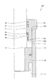
- FIG. 1 is a sectional view showing a part of a hydraulic cylinder according to a first embodiment of the present invention.
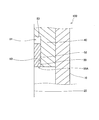
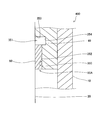
- FIG. 2 is a cross-sectional view showing the bush and the accommodating recess of the hydraulic cylinder according to the first embodiment of the present invention.
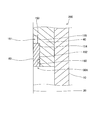
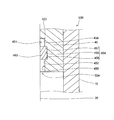
- FIG. 3 is a cross-sectional view showing a bush and an accommodation recess of a hydraulic cylinder according to the second embodiment of the present invention.
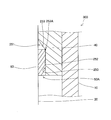
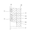
- FIG. 4 is a cross-sectional view showing a bush and an accommodation recess of a hydraulic cylinder according to a third embodiment of the present invention.
- FIG. 5 is a cross-sectional view showing a bush and an accommodation recess of a hydraulic cylinder according to a fourth embodiment of the present invention.
- FIG. 1 is a sectional view showing a part of a hydraulic cylinder according to a first embodiment of the present invention.
- FIG. 2 is a cross-sectional view showing the bush and the accommodating recess of the hydraulic cylinder according to the first embodiment of the present invention
- FIG. 6 is a cross-sectional view showing a bush and an accommodation recess of a hydraulic cylinder according to a fifth embodiment of the present invention.
- FIG. 7 is a cross-sectional view showing a bush and a housing recess of a hydraulic cylinder according to a comparative example of the present invention.
- the hydraulic cylinder 100 is connected to a bottomed cylindrical cylinder tube 10 having an opening 10 ⁇ / b> A at one end, a piston rod 20 inserted into the cylinder tube 10, and a tip of the piston rod 20.
- the piston 30 which divides the inside of the cylinder tube 10 into the rod side chamber 2 and the bottom side chamber 3, and the cylinder head 40 which is provided in the opening part 10A of the cylinder tube 10 and the piston rod 20 penetrates are provided.
- the hydraulic cylinder 100 is used as a lift cylinder that lifts and lowers the load of a forklift.
- the cylinder tube 10 is connected to a body rod (not shown) of a forklift, and the piston rod 20 is connected to a fork (not shown) on which a load is placed.
- the hydraulic cylinder 100 is mounted on the body of the forklift so that the central axis extends in the vertical direction. As the hydraulic cylinder 100 expands and contracts, the fork moves up and down.
- the rod side chamber 2 in the cylinder tube 10 is filled with gas, and the bottom side chamber 3 is supplied and discharged with hydraulic oil as hydraulic fluid.
- the hydraulic cylinder 100 is extended by the hydraulic pressure guided to the bottom chamber 3 from a hydraulic pressure source (hydraulic pressure source). When the hydraulic pressure in the bottom side chamber 3 decreases, the piston rod 20 and the piston 30 move downward due to their own weight, and the hydraulic cylinder 100 contracts.
- the cylinder head 40 is fixed to the cylinder tube 10.
- a main seal 41 and a dust seal 42 are interposed on the inner periphery of the cylinder head 40.
- the main seal 41 is in sliding contact with the outer peripheral surface of the piston rod 20 and seals the rod side chamber 2 in the cylinder tube 10.
- the dust seal 42 prevents dust from entering the cylinder tube 10.
- a hydraulic cylinder 600 as a comparative example will be described with reference to FIG.
- the same configuration as the hydraulic cylinder 100 will be described using the same reference numerals.
- the hydraulic cylinder 600 includes an annular bush 60 provided on the inner periphery of the cylinder head 40 and slidably supporting the piston rod 20, and an inner bush of the cylinder head 40.
- the bush 60 is a so-called metal bush made of metal.
- the bush 60 is inserted from the inlet 50A of the housing recess 550 and is press-fitted into the housing recess 550 until it contacts the bottom 553.
- the grease filling groove 551 is formed apart from the housing recess 550 in the axial direction.
- the grease filling groove 551 is filled with the grease 70.
- the hydraulic cylinder 600 it is necessary to form the accommodation recess 550 into which the bush 60 is press-fitted and the grease filling groove 551 into which the grease 70 is filled on the inner periphery of the cylinder head 40, respectively.
- the grease filling groove 551 does not open on the end surface of the cylinder head 40 but opens only on the inner peripheral surface of the cylinder head 40. For this reason, the grease filling groove 551 is particularly difficult to process, and the processing accuracy is reduced and the occurrence of flash is likely to occur. For this reason, in the hydraulic cylinder 600, the manufacturing efficiency may be reduced.
- the hydraulic cylinder 100 includes an annular bush 60 provided on the inner periphery of the cylinder head 40 and slidably supporting the piston rod 20. And an annular housing recess 50 into which the bush 60 is press-fitted, while the grease filling groove 551 is not provided.
- the bush 60 is press-fitted into the housing recess 50 from an inlet 50A that opens into the rod side chamber 2.
- the housing recess 50 includes a cylindrical press-fit portion 52 that is an inner peripheral surface of the cylinder head 40 into which the bush 60 is press-fit, and a bottom surface 53 that is perpendicular to the central axis of the cylinder head 40.
- the accommodation recess 50 is an annular recess having a rectangular cross section.
- the bush 60 is formed such that the overall length in the axial direction is shorter than the overall length in the axial direction of the housing recess 50.
- the bush 60 is press-fitted until the end surface facing the rod side chamber 2 substantially coincides with the end surface of the cylinder head 40 by using a press-fitting jig (not shown) for adjusting the press-fitting length. For this reason, a bottom gap 51 is formed between the bush 60 and the bottom surface 53 of the housing recess 50.
- the bottom gap 51 at the bottom of the housing recess 50 is filled with grease 70 as a lubricant (see FIG. 1).
- grease 70 as a lubricant
- the lubricant may be an impregnated material impregnated with grease, for example.
- the lubricant may be any material that forms a lubricant film on the outer periphery of the piston rod 20 and improves the lubricity of the piston rod 20.
- a grease nipple for filling the grease 70 into the bottom gap 51 may be provided in the cylinder head 40.
- the grease filling groove 551 for filling the grease 70 is independent of the inner periphery of the cylinder head 40. There is no need to form.
- the bottom gap 51 can be easily formed by forming the accommodation recess 50 having a rectangular cross section deep, or conversely shortening the length of the bush 60.
- a hydraulic cylinder 200 according to a second embodiment of the present invention will be described with reference to FIG. Below, it demonstrates centering on a different point from the said 1st Embodiment, the same code
- the housing recess 50 is an annular recess having a bottom surface 53 perpendicular to the central axis of the cylinder head 40 and having a rectangular cross section.
- the housing recess 150 is formed perpendicular to the press-fitting portion 152, which is the inner peripheral surface of the cylinder head 40 into which the bush 60 is press-fitted, and the central axis of the cylinder head 40.
- the press-fitting portion 152 which is the inner peripheral surface of the cylinder head 40 into which the bush 60 is press-fitted, and the central axis of the cylinder head 40.
- it has a stepped portion 154 as a contacting portion that contacts the bottom surface 153 and a cylindrical surface-shaped gap partitioning portion 155 that is formed from the radially inner side of the stepped portion 154 toward the bottom surface 153. This is different from the first embodiment.
- the bush 60 is press-fitted into the press-fit portion 152 until it contacts the stepped portion 154.
- the stepped portion 154 defines the press-fit length of the bush 60 into the housing recess 150.
- a bottom gap 151 filled with the grease 70 is defined by the end surface of the bush 60 that contacts the stepped portion 154, the bottom surface 153 of the housing recess 150, and the clearance partitioning section 155.
- the gap partitioning part 155 is formed in a cylindrical surface shape having an inner diameter smaller than the press-fitting part.
- the gap partitioning portion 155 is not limited to a cylindrical surface shape, and may be formed in a tapered shape or a curved surface shape, for example.
- the press-fitting length of the bush 60 into the housing recess 150 is defined by the step portion 154. Therefore, the bottom gap 151 can be formed on the bottom side of the housing recess 150 without using a press-fitting jig. Therefore, the assemblability of the hydraulic cylinder 200 can be improved.
- the housing recess 150 has a step 154 as a contact portion perpendicular to the central axis.
- the accommodating recess 250 of the hydraulic cylinder 300 has a cylindrical press-fit portion 252 which is the inner peripheral surface of the cylinder head 40 into which the bush 60 is press-fitted, and a tapered shape whose inner diameter gradually increases along the axial direction.
- the second embodiment is different from the second embodiment in that a boundary portion 253A between the press-fit portion 252 and the bottom surface 253 functions as a contact portion.
- the accommodating recess 250 has a cylindrical surface-shaped press-fitting portion 252 that is an inner peripheral surface of the cylinder head 40 into which the bush 60 is press-fitted, and an inner diameter as it approaches the inlet portion 50 ⁇ / b> A side along the axial direction. And a tapered bottom surface 253 that gradually increases. Note that the bottom surface 253 is not limited to a tapered shape, and may be formed such that the inner diameter gradually increases toward the inlet portion 50A side, for example, a curved surface.
- the bush 60 is press-fitted into the press-fitting part 252 until it abuts on a boundary part 253A with the press-fitting part 252 on the bottom surface 253 of the housing recess 250.
- the boundary portion 253A of the bottom surface 253 with the press-fit portion 252 serves as a contact portion that defines the press-fit length of the bush 60 into the housing recess 250.
- the bottom surface 253 of the housing recess 250 is tapered, a bottom gap 251 is formed between the end surface of the bush 60 and the bottom surface 253 of the housing recess 250.
- the bottom gap 251 is filled with the grease 70 as in the first embodiment.
- the bottom surface 253 of the housing recess 250 is formed in a taper shape, so that the bush 60 abuts on a boundary portion 253A between the press-fit portion 252 and the bottom surface 253 of the housing recess 250.
- the press-fitting length of the bush 60 into the accommodation recess 250 is defined by the boundary portion 253A. Therefore, the bottom gap 151 can be formed between the housing recess 150 and the bottom surface 153 without adjusting the press-fitting length of the bush 60 with the press-fitting jig. Therefore, the assemblability of the hydraulic cylinder 200 can be improved.
- the housing recess 350 is formed with a larger inner diameter than the press-fit portion 352 between the press-fit portion 352 that is the inner peripheral surface of the cylinder head 40 into which the bush 60 is press-fit, and the press-fit portion 352 and the bottom surface 353. And a large-diameter portion 354 that divides the bottom gap 351 from the first embodiment.
- the large-diameter portion 354 of the accommodating recess 350 has a larger inner diameter than the press-fit portion 352 and is formed in a cylindrical surface shape.
- a bottom gap 351 filled with the grease 70 is formed by the bottom surface 353 of the housing recess 350, the large diameter portion 354, and the end surface of the bush 60.
- the bottom surface 353 may be formed such that the inner diameter gradually increases toward the inlet 50A side, and may be formed in a tapered shape or a curved surface, for example.
- the large diameter portion 354 is not limited to the cylindrical surface shape, and may be formed in a tapered shape or a curved surface shape. Moreover, you may provide the contact part which the bush 60 contact
- the accommodating recess 350 has a large diameter portion 354 formed with an inner diameter larger than that of the press-fit portion 352, so that the volume of the bottom gap 351 can be increased. Therefore, the amount of grease 70 filled in the bottom gap 351 can be increased.
- the bush 60 is formed of metal, and is press-fitted into the press-fit portion 52 of the housing recess 50 and is fixed to the cylinder head 40.
- the bush 460 is formed of a resin material that can be expanded and contracted by an external force, and is attached to the cylinder head 40 by being locked to the positioning portion 454 of the housing recess 450.
- the accommodation recess 450 of the hydraulic cylinder 500 is provided between the introduction part 452 formed from the inlet part 50 ⁇ / b> A, and between the introduction part 452 and the bottom surface 453, and locks the bush 460 in the axial direction.
- the positioning portion 454 connects the mounting cylindrical surface 455 formed with an inner diameter that is larger than the inner diameter of the introduction portion 452 and slightly smaller than the outer diameter of the bush 460, and connects the attachment cylindrical surface 455 and the introduction portion 452 to the central axis.
- the introduction portion 452 and the gap forming portion 458 are formed as cylindrical surfaces having an outer diameter of the bush 460 and an inner diameter smaller than the mounting cylindrical surface 455 of the positioning portion 454, respectively.
- the bush 460 is elastically deformed by an external force to reduce the outer diameter, and is inserted into the introduction portion 452.
- the bush 460 When the bush 460 is inserted up to the positioning portion 454, the outer diameter of the elastically deformed bush 460 returns to the original, and the bush 460 has an outer diameter substantially the same as the inner diameter of the mounting cylindrical surface 455. Accordingly, the movement of the bush 460 in the axial direction is restricted by the first and second side walls 456 and 457 of the positioning portion 454 and is locked to the positioning portion 454. As a result, the bush 460 is attached to the receiving recess 450 while being prevented from coming off from the receiving recess 450. As described above, the bush 460 is not press-fitted and fixed to the receiving recess 450 as in the first embodiment, but is attached to the receiving recess 450 with restricted axial movement as in the fifth embodiment. But you can.
- the bottom gap 451 filled with the grease 70 is formed by the bottom surface 453 of the receiving recess 450, the gap forming portion 458, and the end surface of the bush 460. Is done.
- the bush 460 is formed of a resin material that is relatively easily elastically deformed.
- the bush 460 is not limited to a resin material, and may be formed of other materials.
- the bush 460 is formed of a resin material that is relatively easily deformed by an external force, and is attached to the cylinder head 40 by being locked to the positioning portion 454 of the housing recess 450. For this reason, the bush 460 can be easily attached to the cylinder head 40 and the number of assembling steps can be reduced as compared with the case where a metal bush is press-fitted.
- Single-acting hydraulic cylinders 100, 200, 300, 400, and 500 have a bottomed cylindrical cylinder tube 10 having an opening 10A at one end, a piston rod 20 inserted into the cylinder tube 10, and a piston rod 20 A piston 30 that is connected to the tip and divides the cylinder tube 10 into a rod side chamber 2 in which gas is filled and a bottom side chamber 3 in which hydraulic oil is supplied and discharged, and a piston rod 20 provided in an opening 10A of the cylinder tube 10 is provided.
- the cylinder head 40 to be inserted, the bush 60 provided on the inner periphery of the cylinder head 40 to slidably support the piston rod 20, and the bushes 60, 460 formed on the inner periphery of the cylinder head 40 are press-fitted from the inlet portion 50A.
- Housing recesses 50, 150, 250, 350, 450, and housing recesses 50, 150, 2 Between the bottom 53,153,253,353,453 and bush 60,460 of 0,350,450, bottom gap 51,151,251,351,451 grease 70 is filled are formed.
- the receiving recess 50 is a rectangle having a press-fit portion 52 that is an inner peripheral surface of the cylinder head 40 into which the bush 60 is press-fitted, and a bottom surface 53 that is perpendicular to the central axis of the cylinder head 40. It is formed in a cross-sectional shape.
- the housing recesses 150, 250 have contact portions (steps 154, boundary portions 253A) with which the bush 60 contacts.
- the housing recess 150 has a press-fit portion 152 that is the inner peripheral surface of the cylinder head 40 into which the bush 60 is press-fitted, and the contact portion is perpendicular to the central axis from the press-fit portion 152. This is a step 154 to be formed.
- the housing recess 250 is formed so that the inner diameter gradually increases toward the press-fit portion 252 that is the inner peripheral surface of the cylinder head 40 into which the bush 60 is press-fitted, and the inlet portion 50A.
- a boundary portion 253A between the press-fit portion 252 and the bottom surface 253 functions as a contact portion.
- the press-fitting length of the bush 60 into the housing recesses 150 and 250 is defined by the contact portions (stepped portion 154, boundary portion 253A). Therefore, the bottom gaps 151 and 251 are formed at the bottoms of the housing recesses 150 and 250 without adjusting the press-fitting length of the bush 60. Therefore, the assemblability of the hydraulic cylinders 200 and 300 can be improved.
- the housing recess 350 is larger than the press-fit portion 352 between the press-fit portion 352 that is the inner peripheral surface of the cylinder head 40 into which the bush 60 is press-fitted, and the press-fit portion 352 and the bottom surface 353.
- a large-diameter portion 354 that is formed with an inner diameter and defines a bottom gap 351.
- the volume of the bottom gap 351 filled with the grease 70 can be increased. Therefore, the filling amount of the grease 70 can be increased.
- the single-acting hydraulic cylinder 500 includes an introduction portion 452 in which a bush 460 is formed to be expandable and contractable in the radial direction by an external force, and an accommodating recess 450 is formed from an inlet portion 50A and has an inner diameter smaller than the outer diameter of the bush 460. , A positioning portion 454 provided between the introduction portion 452 and the bottom surface 453 for locking and positioning the bush 460 in the axial direction, and a gap forming between the positioning portion 454 and the bottom surface 453 to define the bottom gap 451. Part 458.
- the bush 460 is relatively easily deformed by an external force and is attached to the cylinder head 40 by being locked to the positioning portion 454 of the housing recess 450. For this reason, the bush 460 can be easily attached to the cylinder head 40 and the number of assembling steps can be reduced as compared with the case where a metal bush is press-fitted.
- Single-acting hydraulic cylinders 100, 200, 300, 400, and 500 are lift cylinders that vertically move the fork of the forklift.
- hydraulic oil is used as the hydraulic fluid, but a water-soluble alternative liquid or the like may be used instead.
- hydraulic cylinders 100, 200, 300, 400, and 500 have been described as being used as lift cylinders that raise and lower the load of a forklift, but may be used for applications other than lift cylinders. .
Landscapes
- Engineering & Computer Science (AREA)
- Physics & Mathematics (AREA)
- Fluid Mechanics (AREA)
- Mechanical Engineering (AREA)
- General Engineering & Computer Science (AREA)
- Actuator (AREA)
Abstract
Description
以下、図面を参照して、本発明の第1実施形態に係る単動型液圧シリンダ100について説明する。以下では、単動型液圧シリンダ100を単に「液圧シリンダ100」と称する。
図3を参照して本発明の第2実施形態に係る液圧シリンダ200について説明する。以下では、上記第1実施形態と異なる点を中心に説明し、上記第1実施形態の液圧シリンダ100と同一の構成には同一の符号を付して説明を省略する。
次に、図4を参照して本発明の第3実施形態に係る液圧シリンダ300について説明する。以下では、上記第2実施形態と異なる点を中心に説明し、上記第2実施形態の液圧シリンダ200と同一の構成には同一の符号を付して説明を省略する。
次に、図5を参照して本発明の第4実施形態に係る液圧シリンダ400について説明する。以下では、上記第1実施形態と異なる点を中心に説明し、上記第1実施形態の液圧シリンダ100と同一の構成には同一の符号を付して説明を省略する。
次に、図6を参照して本発明の第5実施形態に係る液圧シリンダ500について説明する。以下では、上記第1実施形態と異なる点を中心に説明し、上記第1実施形態の液圧シリンダ100と同一の構成には同一の符号を付して説明を省略する。
Claims (8)
- 単動型液圧シリンダであって、
一端に開口部を有する有底筒状のシリンダチューブと、
前記シリンダチューブに挿入されるピストンロッドと、
前記ピストンロッドの先端に連結され前記シリンダチューブ内を気体が充填されるロッド側室と作動液が給排されるボトム側室とに区画するピストンと、
前記シリンダチューブの前記開口部に設けられ前記ピストンロッドが挿通するシリンダヘッドと、
前記シリンダヘッドの内周に取り付けられ前記ピストンロッドを摺動自在に支持するブッシュと、
前記シリンダヘッドの内周に形成され入口部から前記ブッシュが挿入される収容凹部と、を備え、
前記収容凹部の底面と前記ブッシュとの間には、潤滑材が充填される底部隙間が形成される単動型液圧シリンダ。 - 請求項1に記載の単動型液圧シリンダであって、
前記収容凹部は、前記ブッシュが圧入される前記シリンダヘッドの内周面である圧入部と、前記シリンダヘッドの中心軸に垂直な前記底面と、を有する矩形断面形状に形成される単動型液圧シリンダ。 - 請求項1に記載の単動型液圧シリンダであって、
前記収容凹部は、前記ブッシュが当接する当接部を有する単動型液圧シリンダ。 - 請求項3に記載の単動型液圧シリンダであって、
前記収容凹部は、前記ブッシュが圧入される前記シリンダヘッドの内周面である圧入部を有し、
前記当接部は、前記圧入部から中心軸に垂直に形成される段差部である単動型液圧シリンダ - 請求項3に記載の単動型液圧シリンダであって、
前記収容凹部の前記底面は、前記入口部に向かって内径が次第に増加するように形成される単動型液圧シリンダ。 - 請求項1に記載の単動型液圧シリンダであって、
前記収容凹部は、
前記ブッシュが圧入される前記シリンダヘッドの内周面である圧入部と、
前記圧入部と前記底面との間に前記圧入部よりも大きな内径で形成されて前記底部隙間を区画する大径部と、を有する単動型液圧シリンダ。 - 請求項1に記載の単動型液圧シリンダであって、
前記ブッシュは、外力によって径方向に拡縮可能に形成され、
前記収容凹部は、
前記入口部から形成され前記ブッシュの外径よりも小さい内径を有する導入部と、
前記導入部と前記底面との間に設けられ前記ブッシュを軸方向に係止して位置決めする位置決め部と、
前記位置決め部と前記底面との間に形成され前記底部隙間を区画する隙間形成部と、を有する単動型液圧シリンダ。 - 請求項1に記載の単動型液圧シリンダであって、
前記単動型液圧シリンダは、フォークリフトのフォークを上下動するリフトシリンダである単動型液圧シリンダ。
Priority Applications (4)
| Application Number | Priority Date | Filing Date | Title |
|---|---|---|---|
| US15/559,821 US10316869B2 (en) | 2015-03-20 | 2016-03-07 | Single-acting hydraulic cylinder |
| DE112016001319.1T DE112016001319T5 (de) | 2015-03-20 | 2016-03-07 | Einfachwirkender Hydraulikzylinder |
| CN201680012761.6A CN107407303B (zh) | 2015-03-20 | 2016-03-07 | 单动型液压缸 |
| KR1020177024141A KR20170128255A (ko) | 2015-03-20 | 2016-03-07 | 단동형 액압 실린더 |
Applications Claiming Priority (2)
| Application Number | Priority Date | Filing Date | Title |
|---|---|---|---|
| JP2015058144A JP6209550B2 (ja) | 2015-03-20 | 2015-03-20 | 単動型液圧シリンダ |
| JP2015-058144 | 2015-03-20 |
Publications (1)
| Publication Number | Publication Date |
|---|---|
| WO2016152482A1 true WO2016152482A1 (ja) | 2016-09-29 |
Family
ID=56978394
Family Applications (1)
| Application Number | Title | Priority Date | Filing Date |
|---|---|---|---|
| PCT/JP2016/057006 Ceased WO2016152482A1 (ja) | 2015-03-20 | 2016-03-07 | 単動型液圧シリンダ |
Country Status (6)
| Country | Link |
|---|---|
| US (1) | US10316869B2 (ja) |
| JP (1) | JP6209550B2 (ja) |
| KR (1) | KR20170128255A (ja) |
| CN (1) | CN107407303B (ja) |
| DE (1) | DE112016001319T5 (ja) |
| WO (1) | WO2016152482A1 (ja) |
Families Citing this family (2)
| Publication number | Priority date | Publication date | Assignee | Title |
|---|---|---|---|---|
| CN108518380B (zh) * | 2018-06-01 | 2024-04-30 | 苏州好特斯模具有限公司 | 快换型立体冷却液压缸 |
| CN112814967B (zh) * | 2021-02-09 | 2025-04-29 | 中国工程物理研究院机械制造工艺研究所 | 一种可调气膜间隙的无摩擦气缸 |
Citations (2)
| Publication number | Priority date | Publication date | Assignee | Title |
|---|---|---|---|---|
| JPS60121508U (ja) * | 1984-01-23 | 1985-08-16 | シーケーデイ株式会社 | 空気圧シリンダ |
| JP2001200810A (ja) * | 2000-01-17 | 2001-07-27 | Kayaba Ind Co Ltd | 液圧シリンダ |
Family Cites Families (11)
| Publication number | Priority date | Publication date | Assignee | Title |
|---|---|---|---|---|
| US2893353A (en) * | 1954-08-13 | 1959-07-07 | Gen Motors Corp | Three position actuator cylinder |
| US4076103A (en) * | 1976-09-13 | 1978-02-28 | Wallis Bernard J | Lubricating means for gas-operated cylinders |
| JPS54115485U (ja) * | 1978-02-01 | 1979-08-13 | ||
| US5052278A (en) * | 1989-03-27 | 1991-10-01 | C.M. Smillie & Company | Fluid cylinder with improved wear rings |
| FR2653511B1 (fr) * | 1989-10-19 | 1993-02-05 | Quiri Cie Sa Usines | Ressort a gaz de hautes performances. |
| CN2460773Y (zh) * | 2001-01-22 | 2001-11-21 | 宝山钢铁股份有限公司 | 伸缩支撑装置 |
| EP1270958B1 (en) * | 2001-06-26 | 2007-05-09 | Kayaba Kogyo Kabushiki Kaisha | Hydraulic cylinder |
| CN2763635Y (zh) * | 2005-01-27 | 2006-03-08 | 浙江大学 | 具有失效自保护功能的磁流变液半主动减振器 |
| CN103967863B (zh) * | 2014-05-09 | 2016-08-24 | 中科华核电技术研究院有限公司 | 吊装用液压缸 |
| CN104006023B (zh) | 2014-06-06 | 2016-03-02 | 徐州徐工液压件有限公司 | 一种利用间隙密封的柱塞缸 |
| US9988793B2 (en) * | 2016-03-14 | 2018-06-05 | Deere & Company | Actuator rod scraper assembly |
-
2015
- 2015-03-20 JP JP2015058144A patent/JP6209550B2/ja active Active
-
2016
- 2016-03-07 CN CN201680012761.6A patent/CN107407303B/zh active Active
- 2016-03-07 DE DE112016001319.1T patent/DE112016001319T5/de not_active Withdrawn
- 2016-03-07 KR KR1020177024141A patent/KR20170128255A/ko not_active Withdrawn
- 2016-03-07 US US15/559,821 patent/US10316869B2/en active Active
- 2016-03-07 WO PCT/JP2016/057006 patent/WO2016152482A1/ja not_active Ceased
Patent Citations (2)
| Publication number | Priority date | Publication date | Assignee | Title |
|---|---|---|---|---|
| JPS60121508U (ja) * | 1984-01-23 | 1985-08-16 | シーケーデイ株式会社 | 空気圧シリンダ |
| JP2001200810A (ja) * | 2000-01-17 | 2001-07-27 | Kayaba Ind Co Ltd | 液圧シリンダ |
Also Published As
| Publication number | Publication date |
|---|---|
| JP6209550B2 (ja) | 2017-10-04 |
| CN107407303B (zh) | 2020-07-24 |
| US10316869B2 (en) | 2019-06-11 |
| KR20170128255A (ko) | 2017-11-22 |
| DE112016001319T5 (de) | 2017-12-21 |
| US20180051722A1 (en) | 2018-02-22 |
| JP2016176566A (ja) | 2016-10-06 |
| CN107407303A (zh) | 2017-11-28 |
Similar Documents
| Publication | Publication Date | Title |
|---|---|---|
| CN104454757B (zh) | 液压缸及其缸盖结构 | |
| JP6748200B2 (ja) | シール構造 | |
| JP5260204B2 (ja) | ガイド機構を備えたガススプリング | |
| CN102753839A (zh) | 流体压缸 | |
| JP6209550B2 (ja) | 単動型液圧シリンダ | |
| US10330170B2 (en) | Shock absorber | |
| WO2018056216A1 (ja) | ショックアブソーバ | |
| CN110392788B (zh) | 储压器 | |
| JP2017032079A (ja) | 複筒型ショックアブソーバ | |
| CN108999830A (zh) | 液压缸、液压驱动系统及工程机械 | |
| CN114517819B (zh) | 单管阻尼器组件和用于其的液压回弹止动组件 | |
| JP2016176566A5 (ja) | ||
| WO2018056099A1 (ja) | 緩衝器 | |
| JP6080257B2 (ja) | 緩衝器 | |
| JP7769522B2 (ja) | シリンダ装置 | |
| KR20170085534A (ko) | 밀봉 가이드 유닛 | |
| JP6343542B2 (ja) | ショックアブソーバ | |
| JP2016217382A (ja) | 液圧シリンダ | |
| CN103791019B (zh) | 减震器 | |
| JP4997332B2 (ja) | ダストブーツ | |
| JP6313593B2 (ja) | クラッチシリンダ用シールリングおよび自動変速機用油圧クラッチ | |
| JP5848646B2 (ja) | オイルシール | |
| JP6037724B2 (ja) | シリンダ装置 | |
| JP2017020617A (ja) | 単筒式ショックアブソーバ | |
| US20070074964A1 (en) | Telescoping fluid actuator |
Legal Events
| Date | Code | Title | Description |
|---|---|---|---|
| 121 | Ep: the epo has been informed by wipo that ep was designated in this application |
Ref document number: 16768385 Country of ref document: EP Kind code of ref document: A1 |
|
| DPE1 | Request for preliminary examination filed after expiration of 19th month from priority date (pct application filed from 20040101) | ||
| ENP | Entry into the national phase |
Ref document number: 20177024141 Country of ref document: KR Kind code of ref document: A |
|
| WWE | Wipo information: entry into national phase |
Ref document number: 15559821 Country of ref document: US |
|
| WWE | Wipo information: entry into national phase |
Ref document number: 112016001319 Country of ref document: DE |
|
| 122 | Ep: pct application non-entry in european phase |
Ref document number: 16768385 Country of ref document: EP Kind code of ref document: A1 |