WO2016152401A1 - 吸気マニホールド装置 - Google Patents
吸気マニホールド装置 Download PDFInfo
- Publication number
- WO2016152401A1 WO2016152401A1 PCT/JP2016/056160 JP2016056160W WO2016152401A1 WO 2016152401 A1 WO2016152401 A1 WO 2016152401A1 JP 2016056160 W JP2016056160 W JP 2016056160W WO 2016152401 A1 WO2016152401 A1 WO 2016152401A1
- Authority
- WO
- WIPO (PCT)
- Prior art keywords
- heat exchanger
- intake manifold
- gas
- manifold device
- resin material
- Prior art date
- Legal status (The legal status is an assumption and is not a legal conclusion. Google has not performed a legal analysis and makes no representation as to the accuracy of the status listed.)
- Ceased
Links
Images


Classifications
-
- F—MECHANICAL ENGINEERING; LIGHTING; HEATING; WEAPONS; BLASTING
- F02—COMBUSTION ENGINES; HOT-GAS OR COMBUSTION-PRODUCT ENGINE PLANTS
- F02B—INTERNAL-COMBUSTION PISTON ENGINES; COMBUSTION ENGINES IN GENERAL
- F02B29/00—Engines characterised by provision for charging or scavenging not provided for in groups F02B25/00, F02B27/00 or F02B33/00 - F02B39/00; Details thereof
- F02B29/04—Cooling of air intake supply
-
- F—MECHANICAL ENGINEERING; LIGHTING; HEATING; WEAPONS; BLASTING
- F02—COMBUSTION ENGINES; HOT-GAS OR COMBUSTION-PRODUCT ENGINE PLANTS
- F02M—SUPPLYING COMBUSTION ENGINES IN GENERAL WITH COMBUSTIBLE MIXTURES OR CONSTITUENTS THEREOF
- F02M35/00—Combustion-air cleaners, air intakes, intake silencers, or induction systems specially adapted for, or arranged on, internal-combustion engines
- F02M35/10—Air intakes; Induction systems
-
- F—MECHANICAL ENGINEERING; LIGHTING; HEATING; WEAPONS; BLASTING
- F02—COMBUSTION ENGINES; HOT-GAS OR COMBUSTION-PRODUCT ENGINE PLANTS
- F02M—SUPPLYING COMBUSTION ENGINES IN GENERAL WITH COMBUSTIBLE MIXTURES OR CONSTITUENTS THEREOF
- F02M35/00—Combustion-air cleaners, air intakes, intake silencers, or induction systems specially adapted for, or arranged on, internal-combustion engines
- F02M35/10—Air intakes; Induction systems
- F02M35/104—Intake manifolds
-
- Y—GENERAL TAGGING OF NEW TECHNOLOGICAL DEVELOPMENTS; GENERAL TAGGING OF CROSS-SECTIONAL TECHNOLOGIES SPANNING OVER SEVERAL SECTIONS OF THE IPC; TECHNICAL SUBJECTS COVERED BY FORMER USPC CROSS-REFERENCE ART COLLECTIONS [XRACs] AND DIGESTS
- Y02—TECHNOLOGIES OR APPLICATIONS FOR MITIGATION OR ADAPTATION AGAINST CLIMATE CHANGE
- Y02T—CLIMATE CHANGE MITIGATION TECHNOLOGIES RELATED TO TRANSPORTATION
- Y02T10/00—Road transport of goods or passengers
- Y02T10/10—Internal combustion engine [ICE] based vehicles
- Y02T10/12—Improving ICE efficiencies
Definitions
- the present invention relates to an intake manifold device including an intake manifold that guides gas to a plurality of cylinder chambers of an internal combustion engine, and a heat exchanger that is built in the intake manifold and cools the gas.
- FIG. 6 of Japanese Patent Application Laid-Open No. 2012-225311 discloses an intake manifold composed of a single member.
- the gas temperature upstream of the heat exchanger in the intake manifold is higher than the gas temperature downstream of the heat exchanger. Therefore, for example, when the intake manifold is made of a single resin material, it is necessary to use a resin material having a relatively high heat resistance that can be applied to the gas temperature on the upstream side. .
- the present invention has been made in consideration of such a problem, and an object thereof is to provide an intake manifold device capable of reducing the material cost.
- an intake manifold apparatus includes an intake manifold that guides gas to a plurality of cylinder chambers of an internal combustion engine, and a heat exchanger that is built in the intake manifold and cools the gas.
- the intake manifold device includes: a first portion that is located upstream of the heat exchanger and is made of a first resin material; and that is located downstream of the heat exchanger and And a second portion made of a second resin material having lower heat resistance than the first resin material, wherein the first portion and the second portion are joined by welding.
- the second portion is configured by the second resin material having lower heat resistance than the first resin material, compared to the case where the entire intake manifold is configured by the first resin material, The material cost of the intake manifold device can be reduced.
- the first part and the second part may be welded to each other on the side of the heat exchanger.
- the heat exchanger can be easily disposed in the intake manifold.
- the heat exchanger is made of a metal material, and the heat exchanger body through which the gas flows and the gas of the heat exchanger body from the outer surface of the heat exchanger body.
- a protruding portion protruding in a direction orthogonal to the flow direction, and a resin member welded to both the first portion and the second portion may be outsert-molded in the protruding portion.
- the heat exchanger can be easily and reliably fixed to the intake manifold. Moreover, since the flow of the gas in the gap (bypass flow path) between the heat exchanger and the intake manifold can be suppressed by the protrusion, the gas cooling efficiency by the heat exchanger can be improved.
- the heat exchanger is made of a metal material, and the heat exchanger body through which the gas flows and the gas of the heat exchanger body from the outer surface of the heat exchanger body.
- the first portion and the second portion may be welded to each other in a state of sandwiching the protrusion.
- the heat exchanger can be easily and reliably fixed to the intake manifold. Moreover, since the flow of the gas in the bypass channel can be suppressed by the protruding portion, the cooling efficiency of the gas by the heat exchanger can be improved.
- a vibration isolating member may be interposed between the intake manifold and the heat exchanger.
- the second portion is constituted by the second resin material having lower heat resistance than the first resin material, the material cost of the intake manifold device can be reduced.
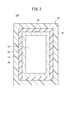
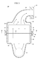
- FIG. 2 is a cross-sectional view taken along line II-II in FIG. It is a partial longitudinal cross-sectional view of the intake manifold apparatus which concerns on 2nd Embodiment of this invention.
- FIG. 4 is a sectional view taken along line IV-IV in FIG. 3.
- the intake manifold device is applied to a multi-cylinder internal combustion engine mounted on a vehicle or the like, and cools gas compressed by a supercharger and guides it to a plurality of cylinder chambers.
- the gas led to the intake manifold device may be a gas led from the intake passage of the internal combustion engine, which may be a mixture of exhaust gas and air of the internal combustion engine, or air that does not contain exhaust gas. There may be.
- an intake manifold device 10 ⁇ / b> A includes an intake manifold 12, a heat exchanger (intercooler) 14 built in the intake manifold 12, an intake manifold 12, and a heat exchanger 14. And an anti-vibration member 16 interposed therebetween.
- the intake manifold 12 includes a first part 18 located on the upstream side of the heat exchanger 14 and a second part 20 located on the downstream side of the heat exchanger 14.
- the first portion 18 is made of the first resin material, and has a tubular introduction portion 22 connected to an intake passage (not shown), and an upstream side of the heat exchanger 14 that cools the gas guided from the introduction portion 22. And a first housing 24 for housing.
- An annular first flange portion 26 is provided at an end of the first housing 24 on the downstream side (second portion 20 side) (see FIG. 2).
- the first flange portion 26 is formed with an annular recess 28 in which the vibration isolation member 16 is disposed.
- An upstream space 30 for guiding the gas guided from the introduction part 22 to the heat exchanger 14 is formed on the upstream side of the heat exchanger 14 in the first housing 24. That is, a relatively high temperature gas compressed by the supercharger flows through the first portion 18.
- the second portion 20 is made of a second resin material having lower heat resistance than the first resin material, and a second housing 32 that houses the downstream side of the heat exchanger 14 and a gas cooled by the heat exchanger 14. And a plurality of branch pipes 34 leading to the plurality of cylinder chambers. A connecting flange 35 connected to a cylinder head (not shown) is provided at the tip of each branch pipe 34.
- An annular second flange portion 36 to be welded to the first flange portion 26 is provided at an end portion on the upstream side (first portion 18 side) of the second housing 32.
- a downstream space 38 for temporarily storing the gas cooled by the heat exchanger 14 is formed in the second housing 32 on the downstream side of the heat exchanger 14. That is, a relatively low temperature gas cooled by the heat exchanger 14 flows through the second portion 20.
- examples of the first resin material and the second resin material include nylon 6 (registered trademark), nylon 6 with glass fiber, nylon 66 (registered trademark), nylon 66 with glass fiber, and the like. Can be mentioned.
- nylon 66 containing glass fiber or nylon 66 nylon 66 not containing glass fiber
- the resin having lower heat resistance than the first resin material is used as the second resin material.
- Material is selected. That is, as the second resin material, nylon 6 containing glass fiber or nylon 6 (nylon 6 not containing glass fiber) is used.
- the heat exchanger 14 is made of a metal material such as aluminum, and has a rectangular parallelepiped heat exchanger body 40 through which gas flows, and an outer surface of the heat exchanger body 40.
- An annular projecting portion 42 projecting in a direction orthogonal to the gas flow direction is provided.
- the heat exchanger main body 40 is formed with a gas flow path through which a gas flows and a refrigerant flow path through which a refrigerant for cooling the gas flows.
- the refrigerant heated by heat exchange with the gas in the heat exchanger main body 40 is led out to a refrigerant circulation passage (not shown) and radiated (cooled) by another heat exchanger, and then the refrigerant in the heat exchanger main body 40. It is introduced into the flow path.
- the projecting portion 42 is positioned substantially at the center in the gas flow direction in the heat exchanger body 40, extends to the annular recess 28 formed in the first flange portion 26, and passes through the vibration isolation member 16 to the first portion 18. And sandwiched between the second portions 20.
- the first flange portion 26 and the second flange portion 36 are welded to each other at the side of the heat exchanger 14 (substantially the center in the gas flow direction of the heat exchanger 14). Thereby, the heat exchanger 14 can be easily disposed in the intake manifold 12.
- the anti-vibration member 16 is an elastic member made of rubber or the like, for example, and at least a part thereof is provided in an annular shape so as to cover the entire outer surface of the protruding portion 42.
- the vibration isolation member 16 is interposed between the heat exchanger body 40 and the first housing 24, between the annular recess 28, and between the heat exchanger body 40 and the second housing 32. Thereby, the heat exchanger 14 is reliably positioned and fixed with respect to the intake manifold 12. Moreover, it can suppress that the heat exchanger 14 vibrates by the distribution
- the intake manifold device 10A is basically configured as described above. Next, the function and effect of the intake manifold device 10A will be described.
- the heat exchanger 14 when the heat exchanger 14 is assembled to the intake manifold 12, for example, the heat exchanger 14 in which the vibration isolation member 16 is provided on the protrusion 42 is inserted into the first housing 24. At this time, the vibration isolation member 16 is positioned in the annular recess 28 of the first portion 18.
- the second part 20 is attached to the first part 18 so that the second flange part 36 contacts the first flange part 26, and the first flange part 26 and the second flange part 36 are vibration welded (joined) to each other.
- the vibration isolation member 16 is interposed between the first flange portion 26 and the heat exchanger body 40 and between the second flange portion 36 and the heat exchanger body 40, the heat exchanger body 40 is connected to the intake manifold. It is possible to suppress hitting 12.
- the protrusion part 42 will be clamped by the 1st flange part 26 and the 2nd flange part 36 via the vibration isolator 16, and the heat exchanger 14 will be carried out. It is positioned and fixed in the intake manifold 12.
- the intake manifold 12 is located on the upstream side of the heat exchanger 14 and is composed of the first resin material 18, and the first portion 18 is located on the downstream side of the heat exchanger 14. And a second portion 20 made of a second resin material having lower heat resistance than the resin material. That is, since it is not necessary to configure the entire intake manifold 12 with the relatively expensive first resin member, the material cost of the intake manifold device 10A can be reduced.
- first flange portion 26 and the second flange portion 36 are welded to each other while the protruding portion 42 of the heat exchanger 14 is sandwiched between the first flange portion 26 and the second flange portion 36, the heat exchanger 14. Can be easily and reliably fixed to the intake manifold 12.
- the gas flow in the gap (bypass passage 44) between the heat exchanger body 40 and the intake manifold 12 is blocked (suppressed) by the protrusion 42 and the vibration isolating member 16, the gas is supplied to the heat exchanger body 40. Can be distributed efficiently. Thereby, the cooling efficiency of the gas by the heat exchanger 14 can be improved.
- An annular resin member 60 is interposed therebetween.
- the resin member 60 is outsert-molded on the protruding portion 42 of the heat exchanger 14 and is vibration welded to both the first flange portion 54 and the second flange portion 58.
- the heat exchanger 14 can be easily and reliably fixed to the intake manifold 50. Further, since the gas flow in the bypass flow path 44 is blocked by the protrusion 42, the gas can be efficiently circulated through the heat exchanger body 40. Thereby, the cooling efficiency of the gas by the heat exchanger 14 can be improved.
- the embodiment described above is not limited to the above configuration.
- the first flange portion 54 and the second flange portion 58 may be located on the downstream side of the heat exchanger 14.
Landscapes
- Engineering & Computer Science (AREA)
- Chemical & Material Sciences (AREA)
- Combustion & Propulsion (AREA)
- Mechanical Engineering (AREA)
- General Engineering & Computer Science (AREA)
- Physics & Mathematics (AREA)
- Thermal Sciences (AREA)
- Lining Or Joining Of Plastics Or The Like (AREA)
Abstract
本発明は吸気マニホールド装置に関する。吸気マニホールド装置(10A)は、熱交換器(14)が内蔵された吸気マニホールド(12)を備える。吸気マニホールド(12)は、熱交換器(14)の上流側に位置する第1部位(18)と、熱交換器(14)の下流側に位置して第1樹脂材料よりも耐熱性の低い第2樹脂材料で構成された第2部位(20)とを、有している。第1部位(18)及び第2部位(20)は、溶着により接合されている。
Description
本発明は、内燃機関の複数のシリンダ室にガスを導く吸気マニホールドと、吸気マニホールドに内蔵されてガスを冷却する熱交換器と、を備えた吸気マニホールド装置に関する。
従来、過給器により圧縮されたガスを吸気マニホールドに内蔵された熱交換器により冷却して複数のシリンダ室に導く吸気マニホールド装置が利用されている。この種の吸気マニホールド装置として、例えば、特開2012-225311号公報の図6等には、単一部材で構成された吸気マニホールドが開示されている。
ところで、上述した吸気マニホールド装置では、吸気マニホールドにおける熱交換器の上流側のガス温度は、熱交換器の下流側のガス温度よりも高くなる。そのため、例えば、吸気マニホールドを単一の樹脂材料により構成する場合、上流側のガス温度に適用可能な耐熱性の比較的高い樹脂材料を用いる必要があり、材料コストが高騰化するという課題がある。
本発明は、このような課題を考慮してなされたものであり、材料コストの低廉化を図ることができる吸気マニホールド装置を提供することを目的とする。
上記目的を達成するために、本発明に係る吸気マニホールド装置は、内燃機関の複数のシリンダ室にガスを導く吸気マニホールドと、前記吸気マニホールドに内蔵されて前記ガスを冷却する熱交換器と、を備えた吸気マニホールド装置であって、前記吸気マニホールドは、前記熱交換器の上流側に位置して第1樹脂材料で構成された第1部位と、前記熱交換器の下流側に位置して前記第1樹脂材料よりも耐熱性の低い第2樹脂材料で構成された第2部位と、を有し、前記第1部位及び前記第2部位は、溶着により接合されていることを特徴とする。
このような構成によれば、第1樹脂材料よりも耐熱性の低い第2樹脂材料により第2部位を構成しているので、吸気マニホールド全体を第1樹脂材料で構成する場合と比較して、吸気マニホールド装置の材料コストの低廉化を図ることができる。
上記の吸気マニホールド装置において、前記第1部位及び前記第2部位は、前記熱交換器の側方で互いに溶着されていてもよい。
このような構成によれば、熱交換器を吸気マニホールド内に容易に配設させることができる。
上記の吸気マニホールド装置において、前記熱交換器は、金属材料で構成されており、前記ガスが流通する熱交換器本体と、前記熱交換器本体の外側面から前記熱交換器本体の前記ガスの流通方向と直交する方向に突出した突出部と、を有し、前記突出部には、前記第1部位及び前記第2部位の両方に溶着される樹脂部材がアウトサート成形されていてもよい。
このような構成によれば、熱交換器を吸気マニホールドに対して容易且つ確実に固定することができる。また、熱交換器と吸気マニホールドとの間の隙間(バイパス流路)のガスの流通を突出部により抑制することができるので、熱交換器によるガスの冷却効率を向上させることができる。
上記の吸気マニホールド装置において、前記熱交換器は、金属材料で構成されており、前記ガスが流通する熱交換器本体と、前記熱交換器本体の外側面から前記熱交換器本体の前記ガスの流通方向と直交する方向に突出した突出部と、を有し、前記第1部位及び前記第2部位は、前記突出部を挟持した状態で互いに溶着されていてもよい。
このような構成によれば、熱交換器を吸気マニホールドに対して容易且つ確実に固定することができる。また、バイパス流路のガスの流通を突出部により抑制することができるので、熱交換器によるガスの冷却効率を向上させることができる。
上記の吸気マニホールド装置において、前記吸気マニホールドと前記熱交換器との間には、防振部材が介設されていてもよい。
このような構成によれば、熱交換器本体へのガスの流通により熱交換器が振動することを抑制することができる。また、第1部位及び第2部位を互いに溶着させる際に熱交換器が吸気マニホールドに当たることを抑制することができる。
本発明によれば、第1樹脂材料よりも耐熱性の低い第2樹脂材料により第2部位を構成しているので、吸気マニホールド装置の材料コストの低廉化を図ることができる。
以下、本発明に係る吸気マニホールド装置について好適な実施形態を挙げ、添付の図面を参照しながら説明する。
本発明に係る吸気マニホールド装置は、車両等に搭載される多気筒の内燃機関に適用されるものであって、過給器により圧縮されたガスを冷却して複数のシリンダ室に導く。この吸気マニホールド装置に導かれるガスは、内燃機関の吸気通路から導かれる気体であって、内燃機関の排気ガスと空気とが混合された気体であってもよいし、排気ガスを含まない空気であってもよい。
(第1実施形態)
図1に示すように、本実施形態に係る吸気マニホールド装置10Aは、吸気マニホールド12と、吸気マニホールド12内に内蔵された熱交換器(インタークーラ)14と、吸気マニホールド12と熱交換器14との間に介設された防振部材16とを備えている。吸気マニホールド12は、熱交換器14の上流側に位置する第1部位18と、熱交換器14の下流側に位置する第2部位20とを備えている。
図1に示すように、本実施形態に係る吸気マニホールド装置10Aは、吸気マニホールド12と、吸気マニホールド12内に内蔵された熱交換器(インタークーラ)14と、吸気マニホールド12と熱交換器14との間に介設された防振部材16とを備えている。吸気マニホールド12は、熱交換器14の上流側に位置する第1部位18と、熱交換器14の下流側に位置する第2部位20とを備えている。
第1部位18は、第1樹脂材料により構成されており、図示しない吸気通路に接続される管状の導入部22と、導入部22から導かれたガスを冷却する熱交換器14の上流側を収容する第1ハウジング24とを有している。第1ハウジング24の下流側(第2部位20側)の端部には、環状の第1フランジ部26が設けられている(図2参照)。第1フランジ部26には、防振部材16が配設される環状凹部28が形成されている。
第1ハウジング24のうち熱交換器14の上流側には、導入部22から導かれたガスを熱交換器14に導くための上流側空間30が形成されている。すなわち、第1部位18には、過給器により圧縮された比較的高温のガスが流通する。
第2部位20は、第1樹脂材料よりも耐熱性の低い第2樹脂材料により構成さており、熱交換器14の下流側を収容する第2ハウジング32と、熱交換器14により冷却されたガスを複数のシリンダ室に導く複数の分岐管34とを有している。なお、各分岐管34の先端部には、図示しないシリンダヘッドに接続される接続フランジ35が設けられている。
第2ハウジング32の上流側(第1部位18側)の端部には、第1フランジ部26に対して溶着される環状の第2フランジ部36が設けられている。第2ハウジング32のうち熱交換器14の下流側には、熱交換器14により冷却されたガスを一時的に溜める下流側空間38が形成されている。すなわち、第2部位20には、熱交換器14により冷却された比較的低温のガスが流通する。
このような吸気マニホールド12において、第1樹脂材料及び第2樹脂材料としては、例えば、ナイロン6(登録商標)、ガラス繊維入りナイロン6、ナイロン66(登録商標)、及びガラス繊維入りナイロン66等が挙げられる。
そして、例えば、第1樹脂材料としてガラス繊維入りナイロン66又はナイロン66(ガラス繊維が含まれていないナイロン66)が用いられる場合、第2樹脂材料として、第1樹脂材料よりも耐熱性の低い樹脂材料が選定される。すなわち、第2樹脂材料として、ガラス繊維入りナイロン6又はナイロン6(ガラス繊維が含まれていないナイロン6)が用いられる。
図1及び図2に示すように、熱交換器14は、アルミニウム等の金属材料で構成されており、ガスが流通する直方体形状の熱交換器本体40と、熱交換器本体40の外側面からガスの流通方向と直交する方向に突出した環状の突出部42とを有している。
詳細な図示は省略するが、熱交換器本体40には、ガスが流通するガス流路と、ガスを冷却する冷媒が流通する冷媒流路とが形成されている。なお、熱交換器本体40においてガスとの熱交換によって熱せられた冷媒は、図示しない冷媒循環通路に導出され、別の熱交換器により放熱(冷却)された後、熱交換器本体40の冷媒流路に導入される。
突出部42は、熱交換器本体40におけるガスの流通方向の略中央に位置し、第1フランジ部26に形成された環状凹部28まで延在して防振部材16を介して第1部位18及び第2部位20に挟持されている。換言すれば、第1フランジ部26及び第2フランジ部36は、熱交換器14の側方(熱交換器14のガスの流通方向の略中央)で互いに溶着されている。これにより、熱交換器14を吸気マニホールド12内に容易に配設させることができる。
防振部材16は、例えば、ゴム等で構成された弾性部材であって、突出部42の外表面の全体を覆うように少なくとも一部が環状に設けられている。防振部材16は、熱交換器本体40と第1ハウジング24との間、環状凹部28、及び熱交換器本体40と第2ハウジング32との間に介設されている。これにより、熱交換器14は、吸気マニホールド12に対して確実に位置決め固定される。また、熱交換器本体40へのガスの流通により熱交換器14が振動することを抑制することができる。
本実施形態に係る吸気マニホールド装置10Aは、基本的には以上のように構成されるものであり、次に、吸気マニホールド装置10Aの作用効果について説明する。
本実施形態において、熱交換器14を吸気マニホールド12に組み付ける場合、例えば、突出部42に防振部材16が設けられた熱交換器14を第1ハウジング24内に挿入する。このとき、防振部材16を第1部位18の環状凹部28に位置させる。
そして、第2フランジ部36が第1フランジ部26に接触するように第2部位20を第1部位18に対して取り付け、第1フランジ部26及び第2フランジ部36を互いに振動溶着(接合)させる。このとき、防振部材16が第1フランジ部26及び熱交換器本体40の間と第2フランジ部36及び熱交換器本体40の間に介在しているため、熱交換器本体40が吸気マニホールド12に対して当たることを抑制することができる。
そして、第1フランジ部26及び第2フランジ部36の溶着が完了すると、突出部42が防振部材16を介して第1フランジ部26及び第2フランジ部36に挟持され、熱交換器14が吸気マニホールド12内に位置決め固定されるに至る。
本実施形態によれば、吸気マニホールド12が、熱交換器14の上流側に位置して第1樹脂材料で構成された第1部位18と、熱交換器14の下流側に位置して第1樹脂材料よりも耐熱性の低い第2樹脂材料で構成された第2部位20とを有している。すなわち、比較的コストの高い第1樹脂部材により吸気マニホールド12の全体を構成する必要がないため、吸気マニホールド装置10Aの材料コストの低廉化を図ることができる。
また、熱交換器14の突出部42を第1フランジ部26及び第2フランジ部36で挟持した状態で第1フランジ部26及び第2フランジ部36を互いに溶着しているので、熱交換器14を吸気マニホールド12に対して容易且つ確実に固定することができる。
さらに、突出部42及び防振部材16により熱交換器本体40と吸気マニホールド12の間の隙間(バイパス流路44)のガスの流通が阻止(抑制)されるので、熱交換器本体40にガスを効率的に流通させることができる。これにより、熱交換器14によるガスの冷却効率を向上させることができる。
(第2実施形態)
次に、第2実施形態に係る吸気マニホールド装置10Bについて説明する。なお、第2実施形態に係る吸気マニホールド装置10Bにおいて、第1実施形態に係る吸気マニホールド装置10Aと同一の構成要素には同一の参照符号を付し、詳細な説明は省略する。
次に、第2実施形態に係る吸気マニホールド装置10Bについて説明する。なお、第2実施形態に係る吸気マニホールド装置10Bにおいて、第1実施形態に係る吸気マニホールド装置10Aと同一の構成要素には同一の参照符号を付し、詳細な説明は省略する。
図3及び図4に示すように、本実施形態に係る吸気マニホールド装置10Bでは、吸気マニホールド50を構成する第1部位52の第1フランジ部54と第2部位56の第2フランジ部58との間に環状の樹脂部材60が介設されている。樹脂部材60は、熱交換器14の突出部42にアウトサート成形されており、第1フランジ部54及び第2フランジ部58の両方に対して振動溶着されている。
このような構成によれば、熱交換器14を吸気マニホールド50に対して容易且つ確実に固定することができる。また、突出部42によりバイパス流路44のガスの流通が阻止されるので、熱交換器本体40にガスを効率的に流通させることができる。これにより、熱交換器14によるガスの冷却効率を向上させることができる。
上述した実施形態は、上記の構成に限定されない。例えば、吸気マニホールド装置10A、10Bにおいて、第1フランジ部54及び第2フランジ部58は、熱交換器14の下流側に位置していてもよい。
Claims (5)
- 内燃機関の複数のシリンダ室にガスを導く吸気マニホールド(12、50)と、前記吸気マニホールド(12、50)に内蔵されて前記ガスを冷却する熱交換器(14)と、を備えた吸気マニホールド装置(10A、10B)であって、
前記吸気マニホールド(12、50)は、
前記熱交換器(14)の上流側に位置して第1樹脂材料で構成された第1部位(18、52)と、
前記熱交換器(14)の下流側に位置して前記第1樹脂材料よりも耐熱性の低い第2樹脂材料で構成された第2部位(20、56)と、を有し、
前記第1部位(18、52)及び前記第2部位(20、56)は、溶着により接合されていることを特徴とする吸気マニホールド装置(10A、10B)。 - 請求項1記載の吸気マニホールド装置(10A、10B)において、
前記第1部位(18、52)及び前記第2部位(20、56)は、前記熱交換器(14)の側方で互いに溶着されていることを特徴とする吸気マニホールド装置(10A、10B)。 - 請求項2記載の吸気マニホールド装置(10B)において、
前記熱交換器(14)は、金属材料で構成されており、
前記ガスが流通する熱交換器本体(40)と、
前記熱交換器本体(40)の外側面から前記熱交換器本体(40)の前記ガスの流通方向と直交する方向に突出した突出部(42)と、を有し、
前記突出部(42)には、前記第1部位(52)及び前記第2部位(56)の両方に溶着される樹脂部材がアウトサート成形されていることを特徴とする吸気マニホールド装置(10B)。 - 請求項2記載の吸気マニホールド装置(10A)において、
前記熱交換器(14)は、金属材料で構成されており、
前記ガスが流通する熱交換器本体(40)と、
前記熱交換器本体(40)の外側面から前記熱交換器本体(40)の前記ガスの流通方向と直交する方向に突出した突出部(42)と、を有し、
前記第1部位(18)及び前記第2部位(20)は、前記突出部(42)を挟持した状態で互いに溶着されていることを特徴とする吸気マニホールド装置(10A)。 - 請求項4記載の吸気マニホールド装置(10A)において、
前記吸気マニホールド(12)と前記熱交換器(14)との間には、防振部材(16)が介設されていることを特徴とする吸気マニホールド装置(10A)。
Applications Claiming Priority (2)
| Application Number | Priority Date | Filing Date | Title |
|---|---|---|---|
| JP2015-059378 | 2015-03-23 | ||
| JP2015059378A JP6437358B2 (ja) | 2015-03-23 | 2015-03-23 | 吸気マニホールド装置 |
Publications (1)
| Publication Number | Publication Date |
|---|---|
| WO2016152401A1 true WO2016152401A1 (ja) | 2016-09-29 |
Family
ID=56978056
Family Applications (1)
| Application Number | Title | Priority Date | Filing Date |
|---|---|---|---|
| PCT/JP2016/056160 Ceased WO2016152401A1 (ja) | 2015-03-23 | 2016-03-01 | 吸気マニホールド装置 |
Country Status (2)
| Country | Link |
|---|---|
| JP (1) | JP6437358B2 (ja) |
| WO (1) | WO2016152401A1 (ja) |
Families Citing this family (1)
| Publication number | Priority date | Publication date | Assignee | Title |
|---|---|---|---|---|
| JP2019035329A (ja) * | 2017-08-10 | 2019-03-07 | 株式会社デンソー | 空気冷却装置 |
Citations (6)
| Publication number | Priority date | Publication date | Assignee | Title |
|---|---|---|---|---|
| JPS6091972U (ja) * | 1983-11-22 | 1985-06-24 | 東洋ラジエーター株式会社 | 過給気用熱交換器 |
| JPH0719133A (ja) * | 1993-06-29 | 1995-01-20 | Komatsu Ltd | 内燃機関の吸気マニホールド |
| JP2009074509A (ja) * | 2007-09-25 | 2009-04-09 | Daikyo Nishikawa Kk | インテークマニホールド |
| JP2012225311A (ja) * | 2011-04-21 | 2012-11-15 | Denso Corp | 吸気装置 |
| JP2014515803A (ja) * | 2011-04-14 | 2014-07-03 | マーレ インターナショナル ゲゼルシャフト ミット ベシュレンクテル ハフツング | 部品及びその製造方法 |
| US20140326222A1 (en) * | 2012-01-19 | 2014-11-06 | Mann+Hummel Gmbh | Suction Pipe Assembly of an Internal Combustion Engine having a Cooling Fluid Intercooler |
-
2015
- 2015-03-23 JP JP2015059378A patent/JP6437358B2/ja not_active Expired - Fee Related
-
2016
- 2016-03-01 WO PCT/JP2016/056160 patent/WO2016152401A1/ja not_active Ceased
Patent Citations (6)
| Publication number | Priority date | Publication date | Assignee | Title |
|---|---|---|---|---|
| JPS6091972U (ja) * | 1983-11-22 | 1985-06-24 | 東洋ラジエーター株式会社 | 過給気用熱交換器 |
| JPH0719133A (ja) * | 1993-06-29 | 1995-01-20 | Komatsu Ltd | 内燃機関の吸気マニホールド |
| JP2009074509A (ja) * | 2007-09-25 | 2009-04-09 | Daikyo Nishikawa Kk | インテークマニホールド |
| JP2014515803A (ja) * | 2011-04-14 | 2014-07-03 | マーレ インターナショナル ゲゼルシャフト ミット ベシュレンクテル ハフツング | 部品及びその製造方法 |
| JP2012225311A (ja) * | 2011-04-21 | 2012-11-15 | Denso Corp | 吸気装置 |
| US20140326222A1 (en) * | 2012-01-19 | 2014-11-06 | Mann+Hummel Gmbh | Suction Pipe Assembly of an Internal Combustion Engine having a Cooling Fluid Intercooler |
Also Published As
| Publication number | Publication date |
|---|---|
| JP6437358B2 (ja) | 2018-12-12 |
| JP2016176460A (ja) | 2016-10-06 |
Similar Documents
| Publication | Publication Date | Title |
|---|---|---|
| US8905008B2 (en) | Gas supply module for a motor vehicle engine, assembly of an engine cylinder head and such a module, and motor vehicle engine comprising such a module | |
| US8375707B2 (en) | Exhaust gas collector | |
| CN103189632B (zh) | 废气再循环冷却结构体 | |
| US10260817B2 (en) | Stacked-plate heat exchanger | |
| CN105026871B (zh) | 热交换器 | |
| JP6273617B2 (ja) | 吸気管における給気冷却器の配置 | |
| US20140060504A1 (en) | Exhaust Gas Recirculation Apparatus and Method for Forming Same | |
| JP2017186954A (ja) | 内燃機関 | |
| CN104428524A (zh) | 进气歧管 | |
| WO2013108603A1 (ja) | 舶用エンジン | |
| US10124663B2 (en) | Exhaust heat recovering device | |
| JP6437358B2 (ja) | 吸気マニホールド装置 | |
| JP6318492B2 (ja) | Egr冷却装置 | |
| JP2013253493A (ja) | 吸気装置 | |
| JP2009180109A (ja) | 排気マニホールド一体型シリンダヘッドの冷却構造 | |
| US10794337B2 (en) | EGR cooler | |
| JP2015025421A (ja) | Egr冷却装置 | |
| JP2005307975A (ja) | 内燃機関用の吸気管装置 | |
| JP2016169644A (ja) | 吸気マニホールド装置 | |
| JP2005325738A (ja) | Egr分配パイプ | |
| US10465597B2 (en) | Charge air cooler assembly | |
| US11274640B2 (en) | Fluid pipe arrangement | |
| WO2016143592A1 (ja) | 吸気マニホールド装置 | |
| JP2018145820A (ja) | 吸気マニホールド装置 | |
| JP2018145819A (ja) | 吸気マニホールド装置 |
Legal Events
| Date | Code | Title | Description |
|---|---|---|---|
| 121 | Ep: the epo has been informed by wipo that ep was designated in this application |
Ref document number: 16768304 Country of ref document: EP Kind code of ref document: A1 |
|
| NENP | Non-entry into the national phase |
Ref country code: DE |
|
| 122 | Ep: pct application non-entry in european phase |
Ref document number: 16768304 Country of ref document: EP Kind code of ref document: A1 |