WO2016152127A1 - タンク、および熱交換器 - Google Patents
タンク、および熱交換器 Download PDFInfo
- Publication number
- WO2016152127A1 WO2016152127A1 PCT/JP2016/001579 JP2016001579W WO2016152127A1 WO 2016152127 A1 WO2016152127 A1 WO 2016152127A1 JP 2016001579 W JP2016001579 W JP 2016001579W WO 2016152127 A1 WO2016152127 A1 WO 2016152127A1
- Authority
- WO
- WIPO (PCT)
- Prior art keywords
- tank
- tubes
- stacking direction
- plate
- flow
- Prior art date
- Legal status (The legal status is an assumption and is not a legal conclusion. Google has not performed a legal analysis and makes no representation as to the accuracy of the status listed.)
- Ceased
Links
Images




Classifications
-
- F—MECHANICAL ENGINEERING; LIGHTING; HEATING; WEAPONS; BLASTING
- F25—REFRIGERATION OR COOLING; COMBINED HEATING AND REFRIGERATION SYSTEMS; HEAT PUMP SYSTEMS; MANUFACTURE OR STORAGE OF ICE; LIQUEFACTION SOLIDIFICATION OF GASES
- F25B—REFRIGERATION MACHINES, PLANTS OR SYSTEMS; COMBINED HEATING AND REFRIGERATION SYSTEMS; HEAT PUMP SYSTEMS
- F25B39/00—Evaporators; Condensers
- F25B39/02—Evaporators
-
- F—MECHANICAL ENGINEERING; LIGHTING; HEATING; WEAPONS; BLASTING
- F25—REFRIGERATION OR COOLING; COMBINED HEATING AND REFRIGERATION SYSTEMS; HEAT PUMP SYSTEMS; MANUFACTURE OR STORAGE OF ICE; LIQUEFACTION SOLIDIFICATION OF GASES
- F25B—REFRIGERATION MACHINES, PLANTS OR SYSTEMS; COMBINED HEATING AND REFRIGERATION SYSTEMS; HEAT PUMP SYSTEMS
- F25B39/00—Evaporators; Condensers
- F25B39/04—Condensers
-
- F—MECHANICAL ENGINEERING; LIGHTING; HEATING; WEAPONS; BLASTING
- F28—HEAT EXCHANGE IN GENERAL
- F28F—DETAILS OF HEAT-EXCHANGE AND HEAT-TRANSFER APPARATUS, OF GENERAL APPLICATION
- F28F9/00—Casings; Header boxes; Auxiliary supports for elements; Auxiliary members within casings
- F28F9/02—Header boxes; End plates
Definitions
- the present disclosure relates to a tank through which a fluid flows and a heat exchanger including the tank.
- the tank is joined to three parts: a tank body part through which the refrigerant flows, a plate part to which the tube is joined, and a plate-like intermediate plate part arranged between the tank body part and the plate part.
- the heat exchanger comprised by this is disclosed (for example, refer patent document 2). According to this three-part structure, it becomes easy to secure a joint area between the parts, and the pressure resistance of the entire tank can be improved.
- the tank body is formed by press working.
- a sag portion having an arcuate cross section is formed at a corner portion of the joint portion of the tank main body portion with the intermediate plate.
- Another object is to provide a heat exchanger including a tank capable of ensuring pressure resistance while improving productivity.
- the tank according to the first aspect of the present disclosure includes a circulation part through which a fluid circulates, and the circulation parts communicate with each other inside the plurality of tubes laminated in the lamination direction.
- the tank includes a tank body, a plate part, and an intermediate plate part.
- a circulation part is formed in the tank body.
- a plurality of tubes are joined to the plate portion.
- the intermediate plate portion has a plate shape and is disposed between the tank main body portion and the plate portion. Between the circulation part and the longitudinal ends of the plurality of tubes, a communication part is provided for communicating the circulation part and the longitudinal ends of the tubes.
- a communication part is provided between the circulation part and the longitudinal ends of the tubes.
- the cross-sectional shape of the flow part seen from the stacking direction at least the ceiling part side far from the plurality of tubes is formed in a circular shape.
- the tank main body portion has a space forming portion that forms a flow portion, and a tank joint portion that is formed in a plate shape and is joined to the intermediate plate portion.
- the direction perpendicular to both the longitudinal direction and the stacking direction of the plurality of tubes is taken as the width direction.
- the tank joint portion is connected to both end portions in the width direction of the space forming portion.
- a portion farthest from the plurality of tubes is defined as the top portion.
- the connecting portions between the space forming portion and the tank joint portion in the tank main body portion viewed from the stacking direction the portion closest to the plurality of tubes is defined as the connecting end portion.
- the diameter of the inscribed circle passing through the top of the space forming part of the tank body viewed from the stacking direction is defined as D1.
- the distance between the connecting end portions adjacent to each other in the width direction in the tank body viewed from the stacking direction is defined as D2.
- L be the length in the stacking direction in the distribution section.
- the total of the cross-sectional areas of the plurality of tubes is A1.
- the tank body is configured to satisfy the relationship of D1> D2 and D2 ⁇ L ⁇ A1.
- the tank main body portion is configured to satisfy the relationship of D1> D2 and D2 ⁇ L ⁇ A1, the connection portion between the space forming portion and the tank joint portion, that is, the tank main body portion. It can suppress that stress concentrates on the corner
- the tank according to the second aspect of the present disclosure includes a circulation part through which a fluid circulates, and the inside of a plurality of tubes that circulate the fluid and are stacked in the stacking direction are in communication with each other. .
- the tank includes a tank body, a plate part, and an intermediate plate part.
- a circulation part is formed in the tank part.
- a plurality of tubes are joined to the plate portion.
- the intermediate plate portion has a plate shape and is disposed between the tank main body portion and the plate portion. Between the flow part and the longitudinal ends of the plurality of tubes, there is provided a communication part that communicates the flow part and the longitudinal ends of the tubes.
- the cross-sectional shape of the flow part seen from the stacking direction at least the ceiling part side far from the plurality of tubes is formed in a circular shape.
- the tank main body portion has a space forming portion that forms a flow portion, and a tank joint portion that is formed in a plate shape and is joined to the intermediate plate portion.
- the direction perpendicular to both the longitudinal direction and the stacking direction of the plurality of tubes is taken as the width direction.
- the tank joint portion is connected to both end portions in the width direction of the space forming portion.
- a connection end surface which is a surface on the flow portion side of the connection portion between the space forming portion and the tank joint portion in the tank main body portion viewed from the stacking direction, is formed in an arc shape protruding toward the flow portion side.
- a portion of the intermediate plate portion corresponding to the connection end surface is provided with a receiving surface that is joined to the connection end surface and formed in an arc shape corresponding to the arc shape of the connection end surface.
- the receiving surface formed in the circular arc shape corresponding to the circular arc shape of the connection end surface on the intermediate plate portion the inner wall surface of the tank main body portion and the inner wall surface of the intermediate plate portion are smoothly connected. be able to. For this reason, it can suppress that stress concentrates on the connection part of a space formation part and a tank junction part, ie, the corner
- the number of manufacturing steps can be reduced. Therefore, it is possible to ensure pressure resistance while improving productivity.
- the heat exchanger according to the third aspect of the present disclosure has a plurality of tubes, a pair of tanks, an inflow port, and an outflow port.
- the plurality of tubes have flow paths through which fluid flows, and are stacked in the stacking direction.
- the pair of tanks extends in the stacking direction and is connected to a plurality of tubes.
- the inflow port allows fluid to flow into at least one of the pair of tanks.
- the outflow port allows fluid to flow out from at least one of the pair of tanks.
- Each of the pair of tanks includes a plate part, a tank body part, and an intermediate plate part.
- One end of a plurality of tubes is connected to the pre-auto part.
- the tank body portion has a flow portion that is joined to the plate portion and extends in the stacking direction.
- the intermediate plate portion has a plate shape and is disposed between the tank main body portion and the plate portion.
- the tank body has a space forming part, a tank joint, and an opening.
- a flow passage is formed in the space forming portion so that at least a part of the cross-sectional shape viewed from the stacking direction has an arc shape.
- the tank joint portion When viewed from the stacking direction, the tank joint portion extends in the width direction, which is a direction orthogonal to both the longitudinal direction and the stacking direction of the plurality of tubes, and is formed on both end sides in the width direction of the space forming portion. Are joined to the intermediate plate portion.
- the opening is formed between the tank joints in the width direction, and communicates the inside of the plurality of tubes and the flow passage.
- the diameter of the largest inscribed circle in the cross section of the circulation part seen from the stacking direction is D1.
- the width of the opening in the width direction is D2.
- a portion that distributes the fluid flowing in from the inlet to the plurality of tubes is referred to as an inlet-side tank portion.
- L be the length in the stacking direction in the circulation part of the inlet side tank part.
- A be the cross-sectional area of the flow path per tube among a plurality of tubes connected to the inlet side tank section.
- the number of the plurality of tubes connected to the inlet side tank unit is n.
- the relationship of D1> D2 and D2 ⁇ L ⁇ A ⁇ n is satisfied.
- the heat exchanger according to the fourth aspect of the present disclosure has a plurality of tubes and a pair of tanks.
- the plurality of tubes have flow paths through which fluid flows, and are stacked in the stacking direction.
- the pair of tanks extend in the stacking direction, and a plurality of tubes are connected.
- Each of the pair of tanks includes a plate part, a tank body part, and an intermediate plate part.
- One end of a plurality of tubes is connected to the plate portion.
- the tank body portion has a flow portion that is joined to the plate portion and extends in the stacking direction.
- the intermediate plate portion has a plate shape and is disposed between the tank main body portion and the plate portion.
- the tank body has a space forming part, a tank joint, and an opening.
- a flow passage is formed so that at least a part of the cross-sectional shape viewed from the stacking direction has an arc shape.
- the tank joint portion When viewed from the stacking direction, the tank joint portion extends in the width direction, which is a direction orthogonal to both the longitudinal direction and the stacking direction of the plurality of tubes, and is formed on both end sides in the width direction of the space forming portion. And joined to the intermediate plate portion.
- the opening is formed between the tank joints in the width direction, and communicates the inside of the plurality of tubes and the flow passage.
- the intermediate plate part is formed with a plate hole that allows the plurality of tubes and the flow part to communicate with each other.
- the diameter of the largest inscribed circle in the cross section of the circulation part seen from the stacking direction is D1.
- the width of the opening in the width direction is D2.
- the thickness dimension in the stacking direction of the plate holes is defined as t1.
- the heat exchanger according to the fifth aspect of the present disclosure has a plurality of tubes and a pair of tanks.
- the plurality of tubes have flow paths through which fluid flows, and are stacked in the stacking direction.
- the pair of tanks extend in the stacking direction, and a plurality of tubes are connected.
- Each of the pair of tanks includes a plate part, a tank body part, and an intermediate plate part.
- One end of a plurality of tubes is connected to the plate portion.
- the tank body portion has a flow portion that is joined to the plate portion and extends in the stacking direction.
- the intermediate plate portion has a plate shape and is disposed between the tank main body portion and the plate portion.
- the tank body has a space forming part and a tank joint.
- a flow passage is formed in the space forming portion so that at least a part of the cross-sectional shape viewed from the stacking direction has an arc shape.
- the tank joint portion When viewed from the stacking direction, the tank joint portion extends in the width direction, which is a direction orthogonal to both the longitudinal direction and the stacking direction of the plurality of tubes, and is formed on both end sides in the width direction of the space forming portion. And joined to the intermediate plate portion.
- connection end surface which is the surface on the flow portion side of the connection portion between the space forming portion and the tank joint portion, is formed in an arc shape protruding toward the flow portion side.
- a portion of the intermediate plate portion corresponding to the connection end surface is provided with a receiving surface that is joined to the connection end surface and formed in an arc shape corresponding to the arc shape of the connection end surface.
- FIG. 3 is a cross-sectional view taken along line III-III in FIG.
- FIG. 4 is a sectional view taken along line IV-IV in FIG. 3.
- FIG. 3 is a cross-sectional view taken along line III-III in FIG.
- FIG. 4 is a sectional view taken along line IV-IV in FIG. 3.
- FIG. 3 is a cross-sectional view taken along line III-III in FIG.
- FIG. 4 is a sectional view taken along line IV-IV in FIG. 3.
- It is a disassembled perspective view which shows the tube and header tank in 1st Embodiment. It is sectional drawing which looked at the tank main-body part in 1st Embodiment from the tube lamination direction.
- the tank of the present disclosure is applied to a header tank of a refrigerant radiator of a supercritical refrigeration cycle that employs carbon dioxide (CO2) as a refrigerant.
- the supercritical refrigeration cycle is a refrigeration cycle that uses ethylene, ethane, nitrogen oxide or the like as a refrigerant in addition to carbon dioxide, and has a high-pressure side pressure that is equal to or higher than the critical pressure of the refrigerant.
- the refrigerant radiator 100 is a heat exchanger that exchanges heat between the refrigerant that circulates inside the tube 110 and the air that circulates outside the tube 110.
- the refrigerant corresponds to a fluid
- the air corresponds to another fluid.
- the refrigerant radiator 100 includes a core portion 101 and a pair of header tanks 140.
- Each member constituting the core portion 101 and the header tank 140 is made of aluminum or an aluminum alloy. Further, the members constituting the core portion 101 and the header tank 140 are assembled by fitting, jig fixing, or the like, and are integrally brazed with a brazing material provided in advance on a necessary portion on the surface of each member.
- the core part 101 has a plurality of tubes 110 having a flat cross section through which a refrigerant flows, and a plurality of fins 120 formed in a wave shape.
- the plurality of tubes 110 and the plurality of fins 120 are alternately stacked.
- the longitudinal direction of the tube 110 is referred to as the tube longitudinal direction.
- the stacking direction of the tubes 110 and the fins 120 is referred to as a tube stacking direction.
- the direction orthogonal to both the tube longitudinal direction and the tube stacking direction is referred to as the width direction.
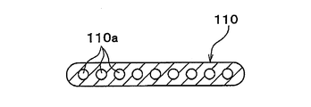
- the tube 110 has a plurality of flow passages 110a arranged in the flat long side direction inside. More specifically, as shown in the cross-sectional view of FIG. 2, the tube 110 of the present embodiment has nine flow passages 110a having a circular cross section. Therefore, the flow passage cross-sectional area A of one tube 110 is the total value of the passage cross-sectional areas of the respective flow passages 110a. When a tube in which one flow passage is formed is adopted, the passage cross-sectional area of one flow passage becomes the flow passage cross-sectional area A of one tube.
- the tube 110 is formed by extrusion molding.
- side plates 130 that reinforce the core portion 101 are provided at both ends of the core portion 101 in the tube stacking direction.
- the side plate 130 extends parallel to the longitudinal direction of the tube, and both ends thereof are connected to the header tank 140.
- the header tank 140 extends in the direction perpendicular to the tube longitudinal direction (that is, the tube stacking direction) at both ends in the tube longitudinal direction and communicates with the plurality of tubes 110.
- the header tank 140 is disposed at the left and right ends of the tubes 110 and extends in the vertical direction to communicate with the plurality of tubes 110.
- header tank 140 and the tube 110 are brazed so that the circulation portion 151 provided in the header tank 140 and the inside of the tube 110 communicate with each other.
- An end cap 180 is brazed to the longitudinal end portion (end portion in the tube stacking direction) of the header tank 140. The end cap 180 closes the opening formed by the flow part 151 of the header tank 140.
- one of the header tanks 140 (the left side in FIG. 1) is joined with a separator 141 for partitioning the internal circulation portion 151 by brazing.
- an inlet joint 191 that forms an inlet for allowing the refrigerant to flow into the circulation portion 151 is joined to the upper side of the separator 141 of one header tank 140 by brazing.
- An outlet joint 192 that forms an outlet for allowing the refrigerant to flow out from the circulation portion 151 is joined to the lower side of the separator 141 of the header tank 140 by brazing.
- the header tank 140 includes a tank main body 150 in which a circulation portion 151 through which a refrigerant flows is formed, a plate portion 160 to which the tube 110 is joined, and a tank main body 150. And an intermediate plate portion 170 disposed between the plate portion 160 and the plate portion 160.
- the tank body 150 includes a space forming part 152 that forms the flow part 151, and a tank joint part 153 that is joined to the intermediate plate part 170 and the plate part 160.
- the space forming portion 152 is formed so that the cross-sectional shape viewed from the tube stacking direction is a substantially arc shape. That is, the space forming portion 152 is formed such that at least a part of its inner wall surface (surface on the flow portion 151 side) has a substantially arc shape. For this reason, as for the cross-sectional shape of the distribution
- An opening 155 is formed on the tube 110 side (intermediate plate portion 170 side) of the space forming portion 152. Through the opening 155, an end portion in the longitudinal direction of the tube 110 (hereinafter referred to as a tube end portion 111) and the circulation portion 151 are communicated.
- the tank joint portion 153 is formed in a plate shape and is connected to both end portions in the width direction of the space forming portion 152. In other words, the tank joint portion 153 is connected to each of the one end portion and the other end portion in the width direction of the space forming portion 152. Therefore, the opening 155 is formed between the two tank joints 153 when viewed from the tube stacking direction.
- the tank joint portion 153 is formed integrally with the space forming portion 152.
- the tank main body 150 having the space forming portion 152 and the tank joint portion 153 thus configured is formed by pressing a flat plate member whose surface is previously clad (coated) with a brazing material.
- the brazing material is clad on the surface of the flat plate member on the tube 110 side.
- the brazing material may be clad on both surfaces of the flat plate member.
- the plate portion 160 is formed in a shape (so-called substantially U-shaped) having two bent portions in which a cross section viewed from the tube stacking direction is bent in the same direction. More specifically, the plate portion 160 includes a flat plate portion 161 formed in a rectangular flat plate shape, and ribs 162 connected to both ends of the flat plate portion 161 in the width direction. The flat plate portion 161 and the rib 162 are integrally formed.
- a tube insertion hole 163 into which the tube end portion 111 is inserted and joined is formed in the flat plate portion 161 of the plate portion 160.
- the plate portion 160 is formed by pressing a flat plate member that is previously clad with a brazing material on both the front surface and the back surface.
- the intermediate plate portion 170 is formed in a rectangular flat plate shape.
- a plate hole 171 penetrating the front and back of the intermediate plate portion 170 is formed at a portion corresponding to the tube end portion 111 in the intermediate plate portion 170.
- a stepped portion 172 as a position restricting portion that restricts the position of the tube end 111 in the middle of the plate thickness is provided at the longitudinal end of the plate hole 171.
- the thickness dimension (length in the tube stacking direction) t1 of the plate hole 171 is larger than the thickness dimension t2 of the tube 110.
- the thickness dimension t2 is the dimension in the short side direction of the flat cross section of the tube 110 or the length of the tube 110 in the tube stacking direction.
- the dimension t1 is set to about twice the dimension t2.
- the intermediate plate portion 170 is formed of a bare material whose surface is not clad with a brazing material.
- the tank body 150, the intermediate plate 170, the plate 160 and the tube 110 configured as described above are assembled as shown in FIGS.
- the distal end position 112 of the tube end portion 111 is restricted to a region outside the circulation portion 151 by the step portion 172 of the plate hole 171 of the intermediate plate portion 170.
- the tube end portion 111 is disposed in the space of the plate hole 171.
- a communication part that connects the flow part 151 and the tube end part 111 is formed by the opening part 155 of the tank main body part 150 and the plate hole 171 of the intermediate plate part 170. Further, the members 150, 170, 160, 110 are integrally brazed by the brazing material provided on the tank main body 150 and the plate portion 160.
- connection end surface 156 the surface on the flow portion 151 side of the connection portion between the space forming portion 152 and the tank joint portion 153 in the tank main body portion 150 viewed from the tube stacking direction.
- connection end surface 156 is inclined from the outer side in the width direction to the inner side (from the outer side to the inner side in FIG. 6) toward the side closer to the tube 110 in the longitudinal direction of the tube (from the upper side to the lower side in FIG. 6). is doing.
- the connection end surface 156 is formed in an arc shape that is recessed toward the outside in the width direction. More specifically, the connection end surface 156 is located on the same arc as the substantially arc-shaped inner wall surface of the space forming portion 152. For this reason, the connection end surface 156 and the inner wall surface (arc surface) of the space forming portion 152 are smoothly connected.
- a portion of the inner wall surface of the space forming portion 152 of the tank main body portion 150 that is farthest from the tube end portion 111 is referred to as a top portion 157.
- a portion of the connecting portion between the space forming portion 152 and the tank joint portion 153 that is closest to the tube end 111 is referred to as a connecting end 158.
- the connection end surface 156 has an arc shape, the connection end portion 158 is formed on each of one side and the other side of the connection end surface 156 in the width direction.
- the diameter of the inscribed circle (see the broken line in FIG. 6) passing through the top 157 of the space forming portion 152 of the tank main body 150 as viewed from the tube stacking direction is D1.
- D1 is the diameter of the largest inscribed circle in the cross section of the flow portion 151 viewed from the tube stacking direction.
- D2 is the distance between the connection end 158 on one side in the width direction and the connection end 158 on the other side.
- D2 is the width of the opening 155.
- L be the length in the tube stacking direction in the distribution section 151. More specifically, a portion of the header tank 140 that distributes the refrigerant flowing from the inlet joint 191 to the tube 110 is referred to as an inlet-side tank portion 140a. In the present embodiment, the portion above the separator 141 of one header tank 140 is the inlet side tank portion 140a. And as shown in FIG. 1, let the length of the tube lamination direction in the distribution
- the sum of the cross-sectional areas of the plurality of tubes 110 is A1. More specifically, the sum total A1 of the channel cross-sectional areas is a value obtained by multiplying the channel cross-sectional area A per one of the plurality of tubes 110 by the number n of the tubes 110 connected to the inlet side tank portion 140a. That is, A ⁇ n.
- the tank body 150 of the present embodiment is configured to satisfy the relationship of D1> D2 and D2 ⁇ L ⁇ A1 (that is, D2 ⁇ L ⁇ A ⁇ n).
- the tank main body 150 is configured to satisfy the relationship D1> D2.
- the tank body 150 is formed by press working, a plurality of pressing steps are not required in order to bring the connecting portion between the space forming portion 152 and the tank joint portion 153 closer to a right angle. Therefore, it can suppress that productivity deteriorates. Therefore, according to the header tank 140 of this embodiment, pressure resistance can be ensured while improving productivity.
- the tank body 150 by configuring the tank body 150 so as to satisfy the relationship of D1> D2, a stress is applied in such a direction that the intermediate plate 170 is pressed against the connection end 158 by the internal pressure.
- the direction in which the intermediate plate portion 170 is pressed against the connection end portion 158 is, in other words, the direction that spreads in the radial direction of the inscribed circle indicated by the broken line of the flow portion 151.
- the tank body 150 is configured to satisfy the relationship of D2 ⁇ L ⁇ A1.
- the flow passage area (D2 ⁇ L) of the opening 155 which is an entrance / exit portion of the tank main body 150 to the flow passage 151 is set to be equal to or larger than the sum (A1) of the flow passage cross-sectional areas of the plurality of tubes 110. it can. Thereby, it can suppress that the pressure loss of the fluid inflow or outflow with respect to the flow part 151 increases.
- the second embodiment is different from the first embodiment in the configuration of the tank main body 150 and the intermediate plate 170.
- the space forming portion 152 of the tank main body 150 is formed so that the cross-sectional shape viewed from the tube stacking direction is substantially U-shaped. Further, the connection end surface 156 of the tank main body 150 is formed in an arc shape protruding toward the flow portion 151.
- a convex portion 173 that protrudes toward the tank main body portion 150 side (the upper side in FIG. 7) is provided.
- the convex portion 173 is formed so that the cross-sectional shape viewed from the tube stacking direction is substantially triangular.
- the convex portion 173 has a receiving surface 174 joined to the connection end surface 156 of the tank main body 150 and a vertical surface 175 perpendicular to the width direction.
- the receiving surface 174 is formed in an arc shape corresponding to the arc shape of the connection end surface 156. That is, the receiving surface 174 is formed in the same arc shape as the arc-shaped connection end surface 156.
- the vertical surface 175 is connected to the end of the receiving surface 174 on the tank body 150 side.
- the vertical surface 175 is smoothly connected to the inner wall surface of the space forming part 152. That is, the vertical surface 175 and the inner wall surface of the space forming part 152 constitute a continuous same plane. In other words, the vertical surface 175 and the inner wall surface of the space forming portion 152 are in a so-called flush state.
- the convex portion 173 of the intermediate plate portion 170 is provided with the receiving surface 174 formed in an arc shape corresponding to the arc shape of the connection end surface 156 of the tank main body portion 150. According to this, the inner wall surface of the tank main body 150 and the inner wall surface of the intermediate plate 170 can be smoothly connected.
- the header tank 140 of this embodiment since it is not necessary to perform press work in order to bring the connecting portion between the space forming portion 152 and the tank joint portion 153 close to a right angle, the number of manufacturing steps can be reduced. Therefore, according to the header tank 140 of this embodiment, pressure resistance can be ensured while improving productivity.
- the intermediate plate portion 170 of this embodiment includes an intermediate joint portion 176 that is joined to the tank joint portion 153 of the tank main body portion 150, and a ceiling portion 154 of the tank main body portion 150 that is more than the intermediate joint portion 176. And a projecting portion 177 disposed on the side close to. Both the intermediate joint portion 176 and the protruding portion 177 are formed in a plate shape extending in a direction orthogonal to the tube longitudinal direction. Further, the intermediate joint 176 is formed integrally with the protrusion 177.
- a plate hole 171 is formed in the protruding portion 177. That is, the projecting portion 177 is formed with a communication portion that allows the flow portion 151 and the tube end portion 111 to communicate with each other.
- the intermediate joint portion 176 is connected to both ends of the protruding portion 177 in the width direction.
- a surface of the connecting portion between the intermediate joint portion 176 and the protruding portion 177 on the tank main body portion 150 side is joined to the connection end surface 156 of the tank main body portion 150. Therefore, the surface on the tank main body 150 side in the connection portion between the intermediate joint portion 176 and the protruding portion 177 in the present embodiment constitutes a receiving surface 174 that is joined to the connection end surface 156 of the tank main body portion 150.
- connection portion between the intermediate joint portion 176 and the protruding portion 177 in the intermediate plate portion 170 is formed in an arc shape corresponding to the arc shape of the connection end surface 156 of the tank main body portion 150.
- a receiving surface 174 is provided. According to this, since the inner wall surface of the tank main body 150 and the inner wall surface of the intermediate plate 170 can be smoothly connected, the same effect as in the second embodiment can be obtained.
- the distance D2 in the width direction between the connecting end portions 158 of the tank body 150 shown in FIG. 9, the thickness dimension t1 of the plate hole 171 and 1 The relationship of the flow path cross-sectional area A of the tube 110 is defined. 9 corresponds to the cross-sectional view taken along the line IX-IX in FIG. 3 described in the first embodiment.
- the header tank 140 of this embodiment is configured to satisfy the relationship of D2 ⁇ t1 ⁇ A. That is, the header tank 140 of the present embodiment is configured to satisfy the relations of D1> D2, D2 ⁇ L ⁇ A ⁇ n, and D2 ⁇ t1 ⁇ A.
- Other configurations of the refrigerant radiator 100 are the same as those in the first embodiment.
- the opening area (that is, D2 ⁇ t1) of the portion to which one tube 110 is connected in the communication portions 155 and 171 is larger than the flow path cross-sectional area A of the single tube 110. can do. Thereby, it is possible to further suppress an increase in pressure loss that occurs when the refrigerant flows from the tube 110 into the circulation portion 151 or an increase in pressure loss that occurs when the refrigerant flows into the tube 110 from the circulation portion 151.
- the protruding portion 177 of the intermediate plate portion 170 of the present embodiment is further circulated from the end portion on the flow portion 151 side of the receiving surface 174 when viewed from the tube stacking direction. It protrudes to the part 151 side. Further, flat surfaces 174 a to be brazed and joined to the inner wall surface of the space forming portion 152 are formed on both side surfaces of the protruding portion 177 in the width direction.
- FIG. 10 is a cross-sectional view corresponding to FIG. 8 described in the third embodiment.
- the flat surface 174a extends in parallel to the tube stacking direction and the tube longitudinal direction. Furthermore, a flat surface 156a to which the flat surface 174a is joined is formed on the inner wall surface of the space forming portion 152.
- Other configurations of the refrigerant radiator 100 are the same as those in the first embodiment.
- connection parts can cover the connection end surface 156 in which the sagging part by press work is easy to be formed.
- a claw portion 164 as a caulking portion is provided on the rib 162 of the plate portion 160, and the three components 150, 160, and 170 are temporarily fixed by caulking with the claw portion 164, and then the three components. 150, 160 and 170 may be joined by brazing.
- tank body 150 is formed by press working
- the tank body 150 may be formed by extrusion.
- the circulation part 151 of the header tank 140 is provided in one row in the width direction of the header tank 140 has been described.
- the circulation part 151 may be provided in a plurality of rows together with the tube 110.
- the tank of the present disclosure may be applied to the refrigerant radiator 100 of the supercritical refrigeration cycle.
- the tank of the present disclosure may be applied to an evaporator that evaporates the refrigerant.
- the tank of the present disclosure may be applied not only to a supercritical refrigeration cycle using carbon dioxide as a refrigerant but also to a normal refrigeration cycle and other heat exchangers used for vehicle engines and the like. Further, the tank of the present disclosure may be applied to products other than the heat exchanger.
Landscapes
- Engineering & Computer Science (AREA)
- Physics & Mathematics (AREA)
- Mechanical Engineering (AREA)
- Thermal Sciences (AREA)
- General Engineering & Computer Science (AREA)
- Heat-Exchange Devices With Radiators And Conduit Assemblies (AREA)
Abstract
タンクは、流通部(151)が形成されるタンク本体部(150)、複数のチューブ(110)が接合されるプレート部(160)、中間プレート部(170)を備える。タンク本体部は、流通部を形成する空間形成部(152)と、中間プレート部に接合されるタンク接合部(153)と、を有している。複数のチューブの長手方向および積層方向の双方に直交する方向を幅方向とする。空間形成部とタンク接合部との接続部のうち、複数のチューブに最も近い部位を接続端部(158)とする。タンク本体部の空間形成部における頂部(157)を通る内接円の直径をD1とする。タンク本体部における、幅方向に隣り合う接続端部同士の距離をD2とする。流通部における積層方向の長さをLとする。複数のチューブの流路断面積の総和をA1とする。タンク本体部は、D1>D2、かつ、D2×L≧A1の関係を満たすように構成されている。
Description
本出願は、当該開示内容が参照によって本出願に組み込まれた、2015年3月20日に出願された日本特許出願2015-057470号、および2016年3月15日に出願された日本特許出願2016-051175号を基にしている。
本開示は、内部に流体が流通するタンク、およびタンクを備える熱交換器に関する。
従来、二酸化炭素を冷媒として採用した冷凍サイクルが知られている。このような冷凍サイクルでは、サイクル内の圧力が高くなるため、冷媒放熱器(放熱用の熱交換器)を構成する各部品(チューブやタンク等)において、耐圧性が必要となる。特にタンクは、冷媒放熱器において最も流路断面積が大きくなるため、特許文献1に記載されているように、より高い耐圧性が要求される。
これに対し、タンクを、冷媒が流通するタンク本体部、チューブが接合されるプレート部、およびタンク本体部とプレート部との間に配置される板状の中間プレート部の3部品を接合することにより構成した熱交換器が開示されている(例えば、特許文献2参照)。この3部品構造によれば、各部品同士の接合面積を確保しやすくなり、タンク全体として耐圧性の向上を狙うことができる。
ところで、本開示の発明者らによる検討によると、上記特許文献1に記載のタンクにおいて、タンク本体部をプレス加工により形成することが考えられる。この場合、タンク本体部における中間プレートとの接合部の角部に断面円弧状のダレ部が形成される。このようなタンク本体部を有するタンクにおいて、内圧が上昇した際には、タンク本体部のダレ部に応力が集中し、高い耐圧性を確保できない可能性がある。
この応力集中を低減するためには、タンク本体部にダレ部が形成されてしまうことを抑制する必要がある。例えば、特許文献1のタンク本体部では、接合部の角部の断面形状を直角状に近づける必要がある。しかしながら、プレス加工にて、ダレ部が形成されてしまうことを抑制するためには、複数回のプレス工程が必要となる。その結果、加工工数が増大して、生産性が悪化するおそれがある。
本開示は上記点に鑑みて、生産性を向上させつつ、耐圧性を確保することができるタンクを提供することを目的とする。
また、生産性を向上させつつ、耐圧性を確保することが可能なタンクを備える熱交換器を提供することを別の目的とする。
本開示の第1態様に係るタンクは、流体が流通する流通部を備え、流体が流通するとともに積層方向に積層された複数のチューブの内部と、流通部とが、互いに連通している。
タンクは、タンク本体部、プレート部、および中間プレート部を備える。タンク本体部には、流通部が形成される。プレート部には、複数のチューブが接合される。中間プレート部は、板状を有し、タンク本体部とプレート部との間に配置される。流通部と複数のチューブの長手方向の端部との間には、流通部とチューブの長手方向の端部とを連通させる連通部が設けられている。積層方向から見た流通部の断面形状は、少なくとも複数のチューブから遠い側の天井部側が円形状に形成されている。タンク本体部は、流通部を形成する空間形成部と、板状に形成されるとともに中間プレート部に接合されるタンク接合部とを有している。
複数のチューブの長手方向および積層方向の双方に直交する方向を幅方向とする。タンク接合部は、空間形成部における幅方向の両端部に接続されている。空間形成部における流通部側の面である内壁面うち、複数のチューブから最も遠い部位を頂部とする。積層方向から見たタンク本体部における、空間形成部とタンク接合部との接続部のうち、複数のチューブに最も近い部位を接続端部とする。積層方向から見たタンク本体部の空間形成部における頂部を通る内接円の直径をD1とする。積層方向から見たタンク本体部における、幅方向に隣り合う接続端部同士の距離をD2とする。流通部における積層方向の長さをLとする。複数のチューブの流路断面積の総和をA1とする。タンク本体部は、D1>D2、かつ、D2×L≧A1の関係を満たすように構成されている。
これによれば、タンク本体部を、D1>D2、かつ、D2×L≧A1の関係を満たすように構成しているので、空間形成部とタンク接合部との接続部、すなわちタンク本体部における中間プレート部との接合部の角部に、応力が集中することを抑制できる。このとき、空間形成部とタンク接合部との接続部を直角状に近づけるためにプレス加工を施す必要がないので、製造工数を低減できる。したがって、生産性を向上させつつ、耐圧性を確保することが可能となる。
また、本開示の第2態様に係るタンクは、流体が流通する流通部を備え、流体が流通するとともに積層方向に積層された複数のチューブの内部と、流通部とが、互いに連通している。
タンクは、タンク本体部、プレート部、中間プレート部を備える。タンク部には、流通部が形成される。プレート部には、複数のチューブが接合される。中間プレート部は、板状を有し、タンク本体部とプレート部との間に配置される。流通部と複数のチューブの長手方向の端部との間には、流通部と複数のチューブの長手方向の端部とを連通させる連通部が設けられている。積層方向から見た流通部の断面形状は、少なくとも複数のチューブから遠い側の天井部側が円形状に形成されている。タンク本体部は、流通部を形成する空間形成部と、板状に形成されるとともに中間プレート部に接合されるタンク接合部とを有している。
複数のチューブの長手方向および積層方向の双方に直交する方向を幅方向とする。タンク接合部は、空間形成部における幅方向の両端部に接続されている。積層方向から見たタンク本体部における、空間形成部とタンク接合部との接続部の流通部側の面である接続端面は、流通部側に向かって突出する円弧状に形成されている。中間プレート部における接続端面と対応する部位には、接続端面に接合されるとともに、接続端面の円弧状に対応する円弧状に形成された受面が設けられている。
これによれば、中間プレート部に、接続端面の円弧状に対応する円弧状に形成された受面を設けることで、タンク本体部の内壁面と中間プレート部の内壁面とを滑らかに接続することができる。このため、空間形成部とタンク接合部との接続部、すなわちタンク本体部における中間プレート部との接合部の角部に、応力が集中することを抑制できる。このとき、空間形成部とタンク接合部との接続部を直角状に近づけるためにプレス加工を施す必要がないので、製造工数を低減できる。したがって、生産性を向上させつつ、耐圧性を確保することが可能となる。
本開示の第3態様に係る熱交換器は、複数のチューブ、一対のタンク、流入口、および流出口を有している。複数のチューブは、内部に流体が流通する流路が形成され、積層方向に積層して配置されている。一対のタンクは、積層方向に延び、複数のチューブと接続される。流入口は、一対のタンクのうち少なくとも一方のタンクに流体を流入させる。流出口は、一対のタンクのうち少なくとも一方のタンクから流体を流出させる。
一対のタンクはそれぞれ、プレート部、タンク本体部、および中間プレート部を備える。プレオート部には、複数のチューブの一端が接続される。タンク本体部は、プレート部に接合されるとともに、積層方向に延びる流通部を有する。中間プレート部は、板状を有し、タンク本体部とプレート部との間に配置される。
タンク本体部は、空間形成部、タンク接合部、および開口部を有している。空間形成部には、積層方向から見た断面形状の少なくとも一部が円弧形状を有するように流通路が形成されている。タンク接合部は、積層方向から見たときに、複数のチューブの長手方向および積層方向の双方に直交する方向である幅方向に延びるとともに、空間形成部の幅方向における両端部側に形成されて、中間プレート部に接合されている。開口部は、幅方向においてタンク接合部の間に形成され、複数のチューブの内部と流通路とを連通させる。
積層方向から見た流通部の断面における最大の内接円の直径をD1とする。幅方向における開口部の幅をD2とする。少なくとも一方のタンクのうち、流入口から流入した流体を複数のチューブに分配する部位を入口側タンク部とする。入口側タンク部の流通部における積層方向の長さをLとする。入口側タンク部に接続された複数のチューブのうちのチューブ1本あたりの流路断面積をAとする。入口側タンク部に接続された複数のチューブの本数をnとする。本開示の第3態様では、D1>D2、かつ、D2×L≧A×nの関係が満たされている。
これによれば、生産性を向上させつつ、耐圧性を確保することが可能なタンクを備える熱交換器を提供することができる。
本開示の第4態様に係る熱交換器は、複数のチューブと一対のタンクを有する。複数のチューブは、内部に流体が流通する流路が形成され、積層方向に積層して配置されている。一対のタンクは、積層方向に延び、複数のチューブが接続される。
一対のタンクはそれぞれ、プレート部、タンク本体部、および中間プレート部を備える。プレート部には、複数のチューブの一端が接続される。タンク本体部は、プレート部に接合されるとともに、積層方向に延びる流通部を有する。中間プレート部は、板状を有し、タンク本体部とプレート部との間に配置される。
タンク本体部は、空間形成部、タンク接合部、および開口部を有する。空間形成部は、積層方向から見た断面形状の少なくとも一部が円弧形状を有するように流通路が形成されている。タンク接合部は、積層方向から見たときに、複数のチューブの長手方向および積層方向の双方に直交する方向である幅方向に延びるとともに、空間形成部の幅方向における両端部側に形成されて、中間プレート部に接合される。開口部は、幅方向においてタンク接合部の間に形成され、複数のチューブの内部と流通路とを連通させる。中間プレート部には、複数のチューブと流通部とを連通させるプレート孔が形成されている。
積層方向から見た流通部の断面における最大の内接円の直径をD1とする。幅方向における開口部の幅をD2とする。プレート孔の積層方向の厚み寸法をt1とする。入口側タンク部に接続された複数のチューブのうちのチューブ1本あたりの流路断面積をAとする。本開示の第4態様では、D1>D2、かつ、D2×t1≧Aの関係が満たされている。
これによれば、生産性を向上させつつ、耐圧性を確保することが可能なタンクを備える熱交換器を提供することができる。
本開示の第5態様に係る熱交換器は、複数のチューブと一対のタンクを有している。複数のチューブは、内部に流体が流通する流路が形成され、積層方向に積層して配置されている。一対のタンクは、積層方向に延び、複数のチューブが接続される。
一対のタンクはそれぞれ、プレート部、タンク本体部、および中間プレート部を備える。プレート部には、複数のチューブの一端が接続される。タンク本体部は、プレート部に接合されるとともに、積層方向に延びる流通部を有する。中間プレート部は、板状を有し、タンク本体部とプレート部との間に配置される。
タンク本体部は、空間形成部とタンク接合部を有している。空間形成部には、積層方向から見た断面形状の少なくとも一部が円弧形状を有するように流通路が形成されている。タンク接合部は、積層方向から見たときに、複数のチューブの長手方向および積層方向の双方に直交する方向である幅方向に延びるとともに、空間形成部の幅方向における両端部側に形成されて、中間プレート部に接合される。
積層方向から見たタンク本体部における、空間形成部とタンク接合部との接続部の流通部側の面である接続端面は、流通部側に向かって突出する円弧状に形成されている。中間プレート部における接続端面と対応する部位には、接続端面に接合されるとともに、接続端面の円弧状に対応する円弧状に形成された受面が設けられている。
これによれば、生産性を向上させつつ、耐圧性を確保することが可能なタンクを備える熱交換器を提供することができる。
本開示についての上記目的およびその他の目的、特徴や利点は、添付の図面を参照しながら下記の詳細な記述により、より明確になる。
第1実施形態における冷媒放熱器を示す正面図である。
第1実施形態におけるチューブの長手方向垂直断面図である。
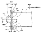
図1のIII-III線における断面図である。
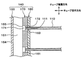
図3のIV-IV線における断面図である。
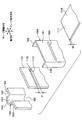
第1実施形態におけるチューブおよびヘッダタンクを示す分解斜視図である。
第1実施形態におけるタンク本体部をチューブ積層方向から見た断面図である。
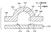
第2実施形態におけるタンク本体部および中間プレート部をチューブ積層方向から見た分解断面図である。
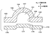
第3実施形態におけるタンク本体部および中間プレート部をチューブ積層方向から見た分解断面図である。
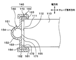
第4実施形態におけるヘッダタンクの断面図である。
第5実施形態におけるタンク本体部および中間プレート部をチューブ積層方向から見た分解断面図である。
他の実施形態(1)におけるチューブおよびヘッダタンクをチューブ積層方向からみた断面図である。
以下、本開示の実施形態について図に基づいて説明する。なお、以下の各実施形態相互において、互いに同一もしくは均等である部分には、図中、同一符号を付して重複する説明を省略する場合がある。各実施形態において構成の一部のみを説明している場合は、構成の他の部分については先行して説明した実施形態と同様とする。各実施形態で具体的に説明している部分の組合せばかりではなく、特に組合せに支障が生じなければ、実施形態同士を部分的に組み合せることも可能である。
(第1実施形態)
第1実施形態について図1~図6に基づいて説明する。本実施形態では、本開示のタンクを、冷媒として二酸化炭素(CO2)を採用した超臨界冷凍サイクルの冷媒放熱器のヘッダタンクに適用している。超臨界冷凍サイクルとは、上記二酸化炭素の他にエチレン、エタン、酸化窒素等を冷媒とする冷凍サイクルであって、高圧側圧力が冷媒の臨界圧力以上になるものを言う。
第1実施形態について図1~図6に基づいて説明する。本実施形態では、本開示のタンクを、冷媒として二酸化炭素(CO2)を採用した超臨界冷凍サイクルの冷媒放熱器のヘッダタンクに適用している。超臨界冷凍サイクルとは、上記二酸化炭素の他にエチレン、エタン、酸化窒素等を冷媒とする冷凍サイクルであって、高圧側圧力が冷媒の臨界圧力以上になるものを言う。
図1に示すように、冷媒放熱器100は、チューブ110の内部を流通する冷媒とチューブ110の外部を流通する空気との間で熱交換を行う熱交換器である。なお、本実施形態では、冷媒が流体に相当し、空気が他の流体に相当している。
冷媒放熱器100は、コア部101および一対のヘッダタンク140備えている。コア部101およびヘッダタンク140を構成する各部材は、アルミニウムあるいはアルミニウム合金により構成されている。また、コア部101およびヘッダタンク140を構成する各部材は、嵌合、治具固定等により組み付けられ、各部材表面の必要部位に予め設けられたろう材により一体でろう付けされている。
コア部101は、内部を冷媒が流通する断面扁平状の複数のチューブ110、および波状に形成された複数のフィン120を有している。複数のチューブ110、および複数のフィン120は、交互に積層配置されている。
以下、チューブ110の長手方向を、チューブ長手方向という。また、チューブ110およびフィン120の積層方向を、チューブ積層方向という。また、チューブ長手方向およびチューブ積層方向の双方に直交する方向を、幅方向という。
チューブ110は、その内部に扁平状の長辺方向に並んだ複数の流通路110aを有している。より具体的には、本実施形態のチューブ110は、図2の断面図に示すように、9つの断面円形状の流通路110aを有している。従って、1本のチューブ110の流路断面積Aは、それぞれの流通路110aの通路断面積の合計値となる。1つの流通路が形成されたチューブを採用する場合、1つの流通路の通路断面積が、1本のチューブの流路断面積Aとなる。チューブ110は、押出成形により形成されている。
コア部101おけるチューブ積層方向の両端部には、図1に示すように、コア部101を補強するサイドプレート130が設けられている。サイドプレート130は、チューブ長手方向と平行に延びてその両端部がヘッダタンク140に接続されている。
ヘッダタンク140は、チューブ長手方向の両端部にてチューブ長手方向と直交する方向(すなわち、チューブ積層方向)に延びて複数のチューブ110と連通するものである。本実施形態では、ヘッダタンク140は、チューブ110の左右端に配置されており、鉛直方向に延びて複数のチューブ110と連通している。
より詳細には、ヘッダタンク140とチューブ110とは、ヘッダタンク140の内部に設けられた流通部151とチューブ110の内部とが互いに連通するようにろう付けされている。そして、ヘッダタンク140の長手方向端部(チューブ積層方向の端部)には、エンドキャップ180がろう付けされている。このエンドキャップ180により、ヘッダタンク140の流通部151によって形成される開口部が閉塞されている。
一対のヘッダタンク140のうち、一方(図1の紙面左側)のヘッダタンク140内には、内部の流通部151を仕切るセパレータ141がろう付けにより接合されている。また、一方のヘッダタンク140のセパレータ141よりも上側には、流通部151に冷媒を流入させる流入口を形成する入口ジョイント191がろう付けにより接合されている。一方のヘッダタンク140のセパレータ141よりも下側には、流通部151から冷媒を流出させる流出口を形成する出口ジョイント192がろう付けにより接合されている。
続いて、本実施形態のヘッダタンク140について詳細に説明する。図3、図4および図5に示すように、ヘッダタンク140は、冷媒が流通する流通部151が形成されるタンク本体部150、チューブ110が接合されるプレート部160、および、タンク本体部150とプレート部160との間に配置される中間プレート部170の3部品を有している。
タンク本体部150は、流通部151を形成する空間形成部152と、中間プレート部170およびプレート部160に接合されるタンク接合部153とを有している。
図3および図4に示すように、空間形成部152は、チューブ積層方向から見た断面形状が略円弧形状となるように形成されている。すなわち、空間形成部152は、その内壁面(流通部151側の面)の少なくとも一部が略円弧形状となるように形成されている。このため、チューブ積層方向から見た流通部151の断面形状は、少なくともチューブ110から遠い側の天井部154側が円形状に形成されている。
空間形成部152のチューブ110側(中間プレート部170側)には、開口部155が形成されている。この開口部155を介して、チューブ110の長手方向の端部(以下、チューブ端部111という)と流通部151とが連通している。
タンク接合部153は、板状に形成されるとともに、空間形成部152における幅方向の両端部側に接続されている。換言すれば、タンク接合部153は、空間形成部152の幅方向の一端部および他端部のそれぞれに接続されている。従って、開口部155は、チューブ積層方向から見たときに、2つのタンク接合部153同士の間に形成されている。タンク接合部153は、空間形成部152と一体に形成されている。
このように構成された空間形成部152およびタンク接合部153を有するタンク本体部150は、表面に予めろう材がクラッド(被覆)された平板部材にプレス加工を施すことにより形成されている。ろう材は、当該平板部材におけるチューブ110側の面にクラッドされている。なお、ろう材は、当該平板部材の両面にクラッドされていてもよい。
プレート部160は、チューブ積層方向から見た断面が、互いに同方向に折り曲げられた2つの折り曲げ部を有する形状(いわゆる、略U字形状)に形成されている。より詳細には、プレート部160は、長方形の平板状に形成された平板部161と、平板部161における幅方向の両端部に接続されたリブ162とを有している。平板部161とリブ162とは、一体に形成されている。
プレート部160の平板部161には、チューブ端部111が挿入接合されるチューブ挿入孔163が形成されている。また、プレート部160は、表面及び裏面の双方に予めろう材がクラッドされた平板部材にプレス加工を施すことにより形成されている。
中間プレート部170は、長方形の平板状に形成されている。中間プレート部170におけるチューブ端部111に対応する部位には、中間プレート部170の表裏を貫通するプレート孔171が形成されている。図5に示すように、プレート孔171の長手方向端部には、板厚の途中でチューブ端部111の位置を規制する位置規制部としての段部172が設けられている。
さらに、プレート孔171の厚み寸法(チューブ積層方向の長さ)t1は、チューブ110の厚さ寸法t2よりも大きい。厚さ寸法t2は、換言すれば、チューブ110の扁平断面の短辺方向の寸法、あるいはチューブ積層方向におけるチューブ110の長さである。本実施形態では、寸法t1は寸法t2の約2倍に設定されている。また、中間プレート部170は、タンク本体部150およびプレート部160とは異なり、表面にろう材がクラッドされていないベア材により形成されている。
上述のように構成されたタンク本体部150、中間プレート部170、プレート部160およびチューブ110は、図3および図4に示すように組み付けられる。このとき、チューブ端部111の先端位置112は、中間プレート部170のプレート孔171の段部172によって、流通部151の外側の領域に規制される。さらに、チューブ端部111は、プレート孔171の空間内に配置されることになる。
そして、タンク本体部150の開口部155と中間プレート部170のプレート孔171とによって、流通部151とチューブ端部111とを連通させる連通部が形成される。また、タンク本体部150およびプレート部160に設けられたろう材によって、各部材150、170、160、110は一体にろう付けされる。
続いて、本実施形態のタンク本体部150について、図6を用いて詳細に説明する。以下、チューブ積層方向から見たタンク本体部150における、空間形成部152とタンク接合部153との接続部の流通部151側の面を、接続端面156という。
接続端面156は、チューブ長手方向におけるチューブ110に対して遠い側から近い側(図6の紙面上側から下側)に向かって、幅方向の外側から内側(図6の紙面外側から内側)に傾斜している。本実施形態では、接続端面156は、幅方向の外側に向けて凹んだ円弧状に形成されている。より詳細には、接続端面156は、空間形成部152の略円弧状の内壁面と同一円弧上に位置している。このため、接続端面156と空間形成部152の内壁面(円弧面)は、滑らかに接続されている。
ここで、タンク本体部150の空間形成部152の内壁面のうち、チューブ端部111から最も遠い部位を頂部157という。また、チューブ積層方向から見たタンク本体部150における、空間形成部152とタンク接合部153との接続部のうち、チューブ端部111に最も近い部位を接続端部158という。本実施形態では、接続端面156が円弧状を有しているため、接続端部158は接続端面156の幅方向の一方側と他方側のそれぞれに形成される。
また、チューブ積層方向から見たタンク本体部150の空間形成部152における頂部157を通る内接円(図6における破線参照)の直径をD1とする。換言すると、D1は、チューブ積層方向から見た流通部151の断面における最大の内接円の直径である。
また、チューブ積層方向から見たタンク本体部150における、幅方向に隣り合う接続端部158同士の幅方向の距離をD2とする。つまり、D2は、幅方向の一方側の接続端部158と他方側の接続端部158との間の距離である。換言すると、D2は、開口部155の幅である。
また、流通部151におけるチューブ積層方向の長さをLとする。より詳細には、ヘッダタンク140のうち、入口ジョイント191から流入した冷媒をチューブ110に分配する部位を、入口側タンク部140aとする。本実施形態では、一方のヘッダタンク140のセパレータ141よりも上側の部位が入口側タンク部140aとなる。そして、図1に示すように、入口側タンク部140aの流通部151におけるチューブ積層方向の長さをLとする。
また、複数のチューブ110の流路断面積の総和をA1とする。より詳細には、流路断面積の総和A1は、複数のチューブ110のうちの1本あたりの流路断面積Aに、入口側タンク部140aに接続されたチューブ110の本数nを乗算した値、すなわち、A×nである。このとき、本実施形態のタンク本体部150は、D1>D2、かつ、D2×L≧A1(すなわち、D2×L≧A×n)の関係を満たすように構成されている。
以上説明したように、本実施形態では、タンク本体部150を、D1>D2の関係を満たすように構成されている。
このため、空間形成部152とタンク接合部153との接続部、すなわちタンク本体部150における中間プレート部170との接合部の角部に、ダレ部が形成されてしまうことを抑制することができる。従って、ヘッダタンク140の内圧が上昇しても、ダレ部に応力が集中してしまうことを抑制することができる。
また、タンク本体部150をプレス加工で形成する際に、空間形成部152とタンク接合部153との接続部を直角状に近づけるために、複数回のプレス工程を必要としない。それゆえ、生産性が悪化してしまうことを抑制することができる。したがって、本実施形態のヘッダタンク140によれば、生産性を向上させつつ、耐圧性を確保することができる。
さらに、タンク本体部150を、上記D1>D2の関係を満たすように構成することにより、内圧によって接続端部158に中間プレート部170を押さえつける向きの応力が加わる。接続端部158に中間プレート部170を押さえつける向きとは、換言すれば、流通部151の破線で示す内接円の径方向に広がる向きである。これにより、タンク本体部150と中間プレート部170とのろう付けが完全にされなかった場合でも、タンク本体部150と中間プレート部170とが分断されることを抑制できる。したがって、耐圧性をより確実に確保することが可能となる。
ところで、チューブ積層方向から見たタンク本体部150における幅方向に隣り合う接続端部158同士の幅方向の距離(D2)を小さくしすぎると、タンク本体部150の開口部155の面積が小さくなる。これにより、流通部151に対して流入または流出する流体の圧力損失が増大するおそれがある。
これに対し、本実施形態では、タンク本体部150を、D2×L≧A1の関係を満たすように構成している。このため、タンク本体部150における流通部151への出入口部分である開口部155の流路面積(D2×L)を、複数のチューブ110の流路断面積の総和(A1)以上とすることができる。これにより、流通部151に対して流入または流出する流体の圧力損失が増大することを抑制できる。
(第2実施形態)
次に、第2実施形態について図7に基づいて説明する。本第2実施形態は、上記第1実施形態と比較して、タンク本体部150および中間プレート部170の構成が異なる。
次に、第2実施形態について図7に基づいて説明する。本第2実施形態は、上記第1実施形態と比較して、タンク本体部150および中間プレート部170の構成が異なる。
図7に示すように、タンク本体部150の空間形成部152は、チューブ積層方向から見た断面形状が略U字状となるように形成されている。また、タンク本体部150の接続端面156は、流通部151側に向かって突出する円弧状に形成されている。
中間プレート部170における接続端面156と対応する部位には、タンク本体部150側(図7の紙面上側)に向かって突出する凸部173が設けられている。凸部173は、チューブ積層方向から見た断面形状が略三角形状となるように形成されている。凸部173は、タンク本体部150の接続端面156に接合される受面174と、幅方向に対して垂直な垂直面175とを有している。
受面174は、接続端面156の円弧状に対応する円弧状に形成されている。すなわち、受面174は、円弧状の接続端面156と同一円弧状に形成されている。
垂直面175は、受面174におけるタンク本体部150側の端部に接続されている。垂直面175は、空間形成部152の内壁面に滑らかに接続されている。すなわち、垂直面175と空間形成部152の内壁面とが、連続した同一平面を構成している。換言すると、垂直面175と空間形成部152の内壁面とが、いわゆる面一の状態となっている。
以上説明したように、本実施形態では、中間プレート部170の凸部173に、タンク本体部150の接続端面156の円弧状に対応する円弧状に形成された受面174を設けている。これによれば、タンク本体部150の内壁面と中間プレート部170の内壁面とを滑らかに接続することができる。
このため、空間形成部152とタンク接合部153との接続部、すなわちタンク本体部150における中間プレート部170との接合部の角部に、接合不良部が形成されてしまうことを抑制することができる。従って、ヘッダタンク140の内圧が上昇した際に、タンク本体部150における中間プレート部170との接合部の角部に応力が集中してしまうことを抑制することができる。
さらに、空間形成部152とタンク接合部153との接続部を直角状に近づけるためにプレス加工を施す必要がないので、製造工数を低減できる。したがって、本実施形態のヘッダタンク140によれば、生産性を向上させつつ、耐圧性を確保することができる。
(第3実施形態)
次に、第3実施形態について図8に基づいて説明する。本第3実施形態は、上記第2実施形態と比較して、中間プレート部170の構成が異なるものである。
次に、第3実施形態について図8に基づいて説明する。本第3実施形態は、上記第2実施形態と比較して、中間プレート部170の構成が異なるものである。
図8に示すように、本実施形態の中間プレート部170は、タンク本体部150のタンク接合部153に接合される中間接合部176と、中間接合部176よりもタンク本体部150の天井部154に近い側に配置される突出部177とを有している。中間接合部176および突出部177は、ともに、チューブ長手方向に直交する方向に延びる板状に形成されている。また、中間接合部176は、突出部177と一体に形成されている。
突出部177には、プレート孔171が形成されている。すなわち、突出部177には、流通部151とチューブ端部111とを連通させる連通部が形成されている。
中間接合部176は、突出部177における幅方向の両端部に接続されている。中間接合部176と突出部177との接続部におけるタンク本体部150側の面は、タンク本体部150の接続端面156に接合されている。したがって、本実施形態における中間接合部176と突出部177との接続部におけるタンク本体部150側の面は、タンク本体部150の接続端面156に接合される受面174を構成している。
以上説明したように、本実施形態では、中間プレート部170における中間接合部176と突出部177との接続部に、タンク本体部150の接続端面156の円弧状に対応する円弧状に形成された受面174を設けている。これによれば、タンク本体部150の内壁面と中間プレート部170の内壁面とを滑らかに接続することができるので、上記第2実施形態と同様の効果を得ることが可能となる。
(第4実施形態)
本実施形態では、第1実施形態のヘッダタンク140に対して、さらに、図9に示すタンク本体部150の接続端部158同士の幅方向の距離D2、プレート孔171の厚み寸法t1、および1本のチューブ110の流路断面積Aの関係を規定している。なお、図9は、第1実施形態で説明した図3のIX-IX線における断面図に対応している。
本実施形態では、第1実施形態のヘッダタンク140に対して、さらに、図9に示すタンク本体部150の接続端部158同士の幅方向の距離D2、プレート孔171の厚み寸法t1、および1本のチューブ110の流路断面積Aの関係を規定している。なお、図9は、第1実施形態で説明した図3のIX-IX線における断面図に対応している。
より詳細には、本実施形態のヘッダタンク140は、D2×t1≧Aの関係を満たすように構成されている。つまり、本実施形態のヘッダタンク140は、D1>D2、かつ、D2×L≧A×n、かつ、D2×t1≧Aの関係を満たすように構成されている。その他の冷媒放熱器100の構成は、第1実施形態と同様である。
従って、本実施形態のヘッダタンク140、および冷媒放熱器100においても、第1実施形態と同様の効果を得ることができる。
さらに、本実施形態では、連通部155、171のうち1本のチューブ110が接続される部位の開口面積(すなわち、D2×t1)を、1本のチューブ110の流路断面積Aよりも大きくすることができる。これにより、冷媒がチューブ110から流通部151へ流入する際に生じる圧力損失、あるいは、冷媒が流通部151からチューブ110へ流入する際に生じる圧力損失の増大をより一層抑制することができる。
(第5実施形態)
本実施形態では、第3実施形態のヘッダタンク140に対して、中間プレート部170の構成を変更した例を説明する。
本実施形態では、第3実施形態のヘッダタンク140に対して、中間プレート部170の構成を変更した例を説明する。
より詳細には、本実施形態の中間プレート部170の突出部177は、図10に示すように、チューブ積層方向から見たときに、受面174の流通部151側の端部から、さらに流通部151側へ突出している。そして、突出部177の幅方向における両側面には、空間形成部152の内壁面に、ろう付け接合される平坦面174aが形成されている。なお、図10は、第3実施形態で説明した図8に対応する断面図である。
平坦面174aは、チューブ積層方向およびチューブ長手方向に平行に広がっている。さらに、空間形成部152の内壁面には、平坦面174aが接合される平坦面156aが形成されている。その他の冷媒放熱器100の構成は、第1実施形態と同様である。
従って、本実施形態のヘッダタンク140、および冷媒放熱器100においても、第3実施形態と同様の効果を得ることができる。
さらに、本実施形態では、タンク本体部150のタンク接合部153と中間プレート部170の中間接合部176が接合されるだけでなく、突出部177の平坦面174aと空間形成部152の内壁面が接合される。そして、これらの接合部によって、プレス加工によるダレ部が形成されやすい接続端面156を覆うことができる。その結果、ヘッダタンク140の内圧が上昇した際に、タンク本体部150における中間プレート部170との接合部の角部に応力が集中してしまうことを、より一層効果的に抑制することができる。
(他の実施形態)
本開示は上述の実施形態に限定されることなく、本開示の趣旨を逸脱しない範囲内で、例えば以下のように種々変形可能である。上記実施形態の構造は、あくまで例示であって、本開示の範囲はこれらの記載の範囲に限定されるものではない。本開示の範囲は、本開示における記載と均等の意味及び範囲内での全ての変更を含むものである。
本開示は上述の実施形態に限定されることなく、本開示の趣旨を逸脱しない範囲内で、例えば以下のように種々変形可能である。上記実施形態の構造は、あくまで例示であって、本開示の範囲はこれらの記載の範囲に限定されるものではない。本開示の範囲は、本開示における記載と均等の意味及び範囲内での全ての変更を含むものである。
(1)上記実施形態では、ヘッダタンク140を構成する3部品(タンク本体部150、プレート部160および中間プレート部170)を、嵌合、治具固定等により組み付けた(仮固定した)後、当該3部品150、160、170をろう付けにより接合した例について説明した。しかしながら、3部品150、160、170の接合方法はこれに限定されない。
例えば、図11に示すように、プレート部160のリブ162にカシメ部としての爪部164を設けるとともに、この爪部164によって当該3部品150、160、170をカシメにより仮固定した後、3部品150、160、170をろう付けにより接合してもよい。
(2)上記第1実施形態では、タンク本体部150をプレス加工により形成した例について説明した。しかしながら、タンク本体部150を押出加工により形成してもよい。
(3)上記実施形態では、ヘッダタンク140の流通部151を、ヘッダタンク140の幅方向に1列設けた例について説明した。しかしながら、流通部151をチューブ110とともに複数列設けてもよい。
(4)上記実施形態では、本開示のタンクを、超臨界冷凍サイクルの冷媒放熱器100に適用した例について説明した。しかしながら、本開示のタンクを、冷媒を蒸発させる蒸発器に適用してもよい。さらに、二酸化炭素を冷媒とする超臨界冷凍サイクルに限らず通常の冷凍サイクルや、その他車両エンジン等に用いられる熱交換器に、本開示のタンクを適用してもよい。また、熱交換器以外の製品に、本開示のタンクを適用してもよい。
(5)上記実施形態では、同一のヘッダタンク140に、入口ジョイント191および出口ジョイント192の双方を接合した例を説明した。しかしながら、一方のヘッダタンク140に入口ジョイント191を接合し、他方のヘッダタンク140に出口ジョイント192を接合してもよい。すなわち、入口ジョイント191および出口ジョイント192を異なるヘッダタンク140に接合してもよい。
Claims (11)
- 流体が流通する流通部(151)を備え、
前記流体が流通するとともに積層方向に積層された複数のチューブ(110)の内部と、前記流通部(151)とが、互いに連通しているタンクであって、
前記流通部(151)が形成されるタンク本体部(150)と、
前記複数のチューブ(110)が接合されるプレート部(160)と、
前記タンク本体部(150)と前記プレート部(160)との間に配置される板状の中間プレート部(170)とを備え、
前記流通部(151)と前記複数のチューブ(110)の長手方向の端部(111)との間には、前記流通部(151)と前記複数のチューブ(110)の長手方向の端部(111)とを連通させる連通部(155、171)が設けられており、
前記積層方向から見た前記流通部(151)の断面形状は、少なくとも前記複数のチューブ(110)から遠い側の天井部(154)側が円形状に形成されており、
前記タンク本体部(150)は、
前記流通部(151)を形成する空間形成部(152)と、
板状に形成されるとともに前記中間プレート部(170)に接合されるタンク接合部(153)と、を有しており、
前記チューブ(110)の長手方向および前記積層方向の双方に直交する方向を幅方向としたとき、
前記タンク接合部(153)は、前記空間形成部(152)における前記幅方向の両端部に接続されており、
前記空間形成部(152)における前記流通部(151)側の面である内壁面うち、前記複数のチューブ(110)から最も遠い部位を頂部(157)とし、
前記積層方向から見た前記タンク本体部(150)における、前記空間形成部(152)と前記タンク接合部(153)との接続部のうち、前記複数のチューブ(110)に最も近い部位を接続端部(158)とし、
前記積層方向から見た前記タンク本体部(150)の前記空間形成部(152)における前記頂部(157)を通る内接円の直径をD1とし、
前記積層方向から見た前記タンク本体部(150)における、前記幅方向に隣り合う前記接続端部(158)同士の距離をD2とし、
前記流通部(151)における前記積層方向の長さをLとし、
前記複数のチューブ(110)の流路断面積の総和をA1としたとき、
前記タンク本体部(150)は、D1>D2、かつ、D2×L≧A1の関係を満たすように構成されているタンク。 - 流体が流通する流通部(151)を備え、
前記流体が流通するとともに積層方向に積層された複数のチューブ(110)の内部と、前記流通部(151)とが、互いに連通しているタンクであって、
前記流通部(151)が形成されるタンク本体部(150)と、
前記複数のチューブ(110)が接合されるプレート部(160)と、
前記タンク本体部(150)と前記プレート部(160)との間に配置される板状の中間プレート部(170)と、を備え、
前記流通部(151)と前記複数のチューブ(110)の長手方向の端部(111)との間には、前記流通部(151)と前記複数のチューブ(110)の長手方向の端部(111)とを連通させる連通部(155、171)が設けられており、
前記積層方向から見た前記流通部(151)の断面形状は、少なくとも前記複数のチューブ(110)から遠い側の天井部(154)側が円形状に形成されており、
前記タンク本体部(150)は、
前記流通部(151)を形成する空間形成部(152)と、
板状に形成されるとともに前記中間プレート部(170)に接合されるタンク接合部(153)と、を有しており、
前記複数のチューブ(110)の長手方向および前記積層方向の双方に直交する方向を幅方向としたとき、
前記タンク接合部(153)は、前記空間形成部(152)における前記幅方向の両端部に接続されており、
前記積層方向から見た前記タンク本体部(150)における、前記空間形成部(152)と前記タンク接合部(153)との接続部の前記流通部(151)側の面である接続端面(156)は、前記流通部(151)側に向かって突出する円弧状に形成されており、
前記中間プレート部(170)における前記接続端面(156)と対応する部位には、前記接続端面(156)に接合されるとともに、前記接続端面(156)の円弧状に対応する円弧状に形成された受面(174)が設けられているタンク。 - 前記中間プレート部(170)における前記接続端面(156)と対応する部位には、前記タンク本体部(150)側に向かって突出する凸部(173)が設けられており、
前記受面(174)は、前記凸部(173)に形成されている請求項2に記載のタンク。 - 前記中間プレート部(170)は、
板状に形成されるとともに、前記タンク本体部(150)の前記タンク接合部(153)に接合される中間接合部(176)と、
板状に形成されるとともに、前記中間接合部(176)よりも前記天井部(154)に近い側に配置される突出部(177)と、を有しており、
前記突出部(177)には、前記連通部(171)が形成されており、
前記受面(174)は、前記中間接合部(176)と前記突出部(177)との接続部に形成されている請求項2に記載のタンク。 - 前記複数のチューブ(110)の内部を流通する前記流体と前記チューブ(110)の外部を流通する他の流体との間で熱交換を行う熱交換器に適用した請求項1ないし4のいずれか1つに記載のタンク。
- 前記タンク本体部(150)、前記プレート部(160)および前記中間プレート部(170)を仮固定するカシメ部(164)をさらに備え、
前記タンク本体部(150)、前記プレート部(160)および前記中間プレート部(170)は、ろう付けにより接合されている請求項1ないし5のいずれか1つに記載のタンク。 - 内部に流体が流通する流路が形成され、積層方向に積層して配置された複数のチューブ(110)と、
前記積層方向に延び、前記複数のチューブ(110)が接続される一対のタンク(140)と、
前記一対のタンク(140)のうち少なくとも一方のタンクに前記流体を流入させる流入口(191)と、
前記一対のタンク(140)のうち少なくとも一方のタンクから前記流体を流出させる流出口(192)と、を有する熱交換器であって、
前記一対のタンク(140)はそれぞれ、
前記複数のチューブ(110)の一端が接続されるプレート部(160)と、
前記プレート部(160)に接合されるとともに、前記積層方向に延びる流通部(151)を有するタンク本体部(150)と、
前記タンク本体部(150)と前記プレート部(160)との間に配置される板状の中間プレート部(170)と、を備え、
前記タンク本体部(150)は、
前記積層方向から見た断面形状の少なくとも一部が円弧形状を有するように流通路が形成された空間形成部(152)と、
前記積層方向から見たときに、前記チューブ(110)の長手方向および前記積層方向の双方に直交する方向である幅方向に延びるとともに、前記空間形成部(152)の前記幅方向における両端部側に形成されて、前記中間プレート部(170)に接合されるタンク接合部(153)と、
前記幅方向において前記タンク接合部(153)の間に形成され、前記複数のチューブ(110)の内部と前記流通路とを連通させる開口部(155)と、を有し、
前記積層方向から見た前記流通部(151)の断面における最大の内接円の直径をD1とし、
前記幅方向における前記開口部(155)の幅をD2とし、
前記少なくとも一方のタンクのうち、前記流入口(191)から流入した流体を前記複数のチューブ(110)に分配する部位を入口側タンク部(140a)とし、前記入口側タンク部(140a)の前記流通部(151)における前記積層方向の長さをLとし、
前記入口側タンク部に接続された前記複数のチューブ(110)のうちのチューブ1本あたりの流路断面積をAとし、
前記入口側タンク部に接続された前記複数のチューブ(110)の本数をnとしたときに、
D1>D2、かつ、D2×L≧A×nの関係を満たす熱交換器。 - 前記中間プレート部(170)には、前記複数のチューブ(110)と前記流通部(151)とを連通させるプレート孔(171)が形成されており、
前記プレート孔(171)の前記積層方向の厚み寸法をt1としたときに、
さらに、D2×t1≧Aの関係を満たす請求項7に記載の熱交換器。 - 内部に流体が流通する流路が形成され、積層方向に積層して配置された複数のチューブ(110)と、
前記積層方向に延び、前記複数のチューブ(110)が接続される一対のタンク(140)と、を有する熱交換器であって、
前記一対のタンク(140)はそれぞれ、
前記チューブ(110)の一端が接続されるプレート部(160)と、
前記プレート部(160)に接合されるとともに、前記積層方向に延びる流通部(151)を有するタンク本体部(150)と、
前記タンク本体部(150)と前記プレート部(160)との間に配置される板状の中間プレート部(170)と、を備え、
前記タンク本体部(150)は、
前記積層方向から見た断面形状の少なくとも一部が円弧形状を有するように流通路が形成された空間形成部(152)と、
前記積層方向から見たときに、前記複数のチューブ(110)の長手方向および前記積層方向の双方に直交する方向である幅方向に延びるとともに、前記空間形成部(152)の前記幅方向における両端部側に形成されて、前記中間プレート部(170)に接合されるタンク接合部(153)と、
前記幅方向において前記タンク接合部(153)の間に形成され、前記チューブの内部と前記流通路とを連通させる開口部(155)と、を有し、
前記中間プレート部(170)には、前記複数のチューブ(110)と前記流通部(151)とを連通させるプレート孔(171)が形成されており、
前記積層方向から見た前記流通部(151)の断面における最大の内接円の直径をD1とし、
前記幅方向における前記開口部(155)の幅をD2とし、
前記プレート孔(171)の前記積層方向の厚み寸法をt1とし、
前記一対のタンク(140)の少なくとも一方のうち、流入口(191)から流入した流体を前記複数のチューブ(110)に分配する部位を入口側タンク部(140a)とし、
前記入口側タンク部(140a)に接続された前記複数のチューブ(110)のうちのチューブ1本あたりの流路断面積をAとしたときに、
D1>D2、かつ、D2×t1≧Aの関係を満たす熱交換器。 - 内部に流体が流通する流路が形成され、積層方向に積層して配置された複数のチューブ(110)と、
前記積層方向に延び、前記複数のチューブ(110)が接続される一対のタンク(140)と、を有する熱交換器であって、
前記タンク(140)は、
前記複数のチューブ(110)の一端が接続されるプレート部(160)と、
前記プレート部(160)に接合されるとともに、前記積層方向に延びる流通部(151)を有するタンク本体部(150)と、
前記タンク本体部(150)と前記プレート部(160)との間に配置される板状の中間プレート部(170)と、を備え、
前記タンク本体部(150)は、
前記積層方向から見た断面形状の少なくとも一部が円弧形状を有するように流通路が形成された空間形成部(152)と、
前記積層方向から見たときに、前記チューブ(110)の長手方向および前記積層方向の双方に直交する方向である幅方向に延びるとともに、前記空間形成部(152)の前記幅方向における両端部側に形成されて、前記中間プレート部(170)に接合されるタンク接合部(153)と、を有し、
前記積層方向から見た前記タンク本体部(150)における、前記空間形成部(152)と前記タンク接合部(153)との接続部の前記流通部(151)側の面である接続端面(156)は、前記流通部(151)側に向かって突出する円弧状に形成されており、
前記中間プレート部(170)における前記接続端面(156)と対応する部位には、前記接続端面(156)に接合されるとともに、前記接続端面(156)の円弧状に対応する円弧状に形成された受面(174)が設けられている熱交換器。 - 前記中間プレート部(170)は、
板状に形成されるとともに、前記タンク本体部(150)の前記タンク接合部(153)に接合される中間接合部(176)と、
板状に形成されるとともに、前記中間接合部(176)よりも前記流通部(151)側に突出する突出部(177)と、を有しており、
前記受面(174)は、前記中間接合部(176)と前記突出部(177)との接続部に形成されており、
前記突出部(177)の前記幅方向における両側面には、前記空間形成部(152)の内壁面に接合される平坦面(174a)が形成されている請求項10に記載の熱交換器。
Priority Applications (2)
| Application Number | Priority Date | Filing Date | Title |
|---|---|---|---|
| US15/550,946 US10317147B2 (en) | 2015-03-20 | 2016-03-18 | Tank and heat exchanger |
| DE112016001307.8T DE112016001307T5 (de) | 2015-03-20 | 2016-03-18 | Behälter und Wärmetauscher |
Applications Claiming Priority (4)
| Application Number | Priority Date | Filing Date | Title |
|---|---|---|---|
| JP2015-057470 | 2015-03-20 | ||
| JP2015057470 | 2015-03-20 | ||
| JP2016-051175 | 2016-03-15 | ||
| JP2016051175A JP6583071B2 (ja) | 2015-03-20 | 2016-03-15 | タンク、および熱交換器 |
Publications (1)
| Publication Number | Publication Date |
|---|---|
| WO2016152127A1 true WO2016152127A1 (ja) | 2016-09-29 |
Family
ID=56978874
Family Applications (1)
| Application Number | Title | Priority Date | Filing Date |
|---|---|---|---|
| PCT/JP2016/001579 Ceased WO2016152127A1 (ja) | 2015-03-20 | 2016-03-18 | タンク、および熱交換器 |
Country Status (1)
| Country | Link |
|---|---|
| WO (1) | WO2016152127A1 (ja) |
Cited By (1)
| Publication number | Priority date | Publication date | Assignee | Title |
|---|---|---|---|---|
| WO2024147225A1 (ja) | 2023-01-06 | 2024-07-11 | ダイキン工業株式会社 | 熱交換器 |
Citations (8)
| Publication number | Priority date | Publication date | Assignee | Title |
|---|---|---|---|---|
| JP2003314987A (ja) * | 2002-02-19 | 2003-11-06 | Denso Corp | 熱交換器 |
| JP2007147172A (ja) * | 2005-11-29 | 2007-06-14 | Showa Denko Kk | 熱交換器 |
| JP2007163040A (ja) * | 2005-12-14 | 2007-06-28 | Showa Denko Kk | 熱交換器用ヘッダタンクおよびこれに用いる外側プレートの製造方法 |
| WO2008025617A1 (fr) * | 2006-08-31 | 2008-03-06 | Valeo Systemes Thermiques | Boitier de distribution d'un fluide caloporteur pour un echangeur de chaleur et echangeur de chaleur comportant un tel boitier |
| JP2009250518A (ja) * | 2008-04-07 | 2009-10-29 | Showa Denko Kk | 熱交換器 |
| JP2009275956A (ja) * | 2008-05-13 | 2009-11-26 | Denso Corp | 熱交換器 |
| JP2009293815A (ja) * | 2008-06-02 | 2009-12-17 | Denso Corp | 熱交換器 |
| JP2010139088A (ja) * | 2008-12-09 | 2010-06-24 | Showa Denko Kk | 熱交換器 |
-
2016
- 2016-03-18 WO PCT/JP2016/001579 patent/WO2016152127A1/ja not_active Ceased
Patent Citations (8)
| Publication number | Priority date | Publication date | Assignee | Title |
|---|---|---|---|---|
| JP2003314987A (ja) * | 2002-02-19 | 2003-11-06 | Denso Corp | 熱交換器 |
| JP2007147172A (ja) * | 2005-11-29 | 2007-06-14 | Showa Denko Kk | 熱交換器 |
| JP2007163040A (ja) * | 2005-12-14 | 2007-06-28 | Showa Denko Kk | 熱交換器用ヘッダタンクおよびこれに用いる外側プレートの製造方法 |
| WO2008025617A1 (fr) * | 2006-08-31 | 2008-03-06 | Valeo Systemes Thermiques | Boitier de distribution d'un fluide caloporteur pour un echangeur de chaleur et echangeur de chaleur comportant un tel boitier |
| JP2009250518A (ja) * | 2008-04-07 | 2009-10-29 | Showa Denko Kk | 熱交換器 |
| JP2009275956A (ja) * | 2008-05-13 | 2009-11-26 | Denso Corp | 熱交換器 |
| JP2009293815A (ja) * | 2008-06-02 | 2009-12-17 | Denso Corp | 熱交換器 |
| JP2010139088A (ja) * | 2008-12-09 | 2010-06-24 | Showa Denko Kk | 熱交換器 |
Cited By (1)
| Publication number | Priority date | Publication date | Assignee | Title |
|---|---|---|---|---|
| WO2024147225A1 (ja) | 2023-01-06 | 2024-07-11 | ダイキン工業株式会社 | 熱交換器 |
Similar Documents
| Publication | Publication Date | Title |
|---|---|---|
| JP4724594B2 (ja) | 熱交換器 | |
| US7044208B2 (en) | Heat exchanger | |
| CN108027225B (zh) | 热交换器、热交换器的制造方法 | |
| JP4724433B2 (ja) | 熱交換器 | |
| JP6583071B2 (ja) | タンク、および熱交換器 | |
| CN110530190B (zh) | 集管箱及换热器 | |
| JP4972488B2 (ja) | 熱交換器 | |
| JP2016200312A (ja) | 熱交換器、および熱交換器の製造方法 | |
| JP4774238B2 (ja) | 冷凍サイクルの冷媒流通部接続構造 | |
| CN115885150A (zh) | 热交换器 | |
| JP2005221151A (ja) | 熱交換器およびヘッダタンク | |
| JP2012159211A (ja) | 熱交換器 | |
| JP2008249241A (ja) | 熱交換器 | |
| JP4533040B2 (ja) | 熱交換器のヘッダタンクと冷媒流通配管との接続構造 | |
| JP6080746B2 (ja) | プレート積層体 | |
| JP2009008347A (ja) | 熱交換器 | |
| JP5154837B2 (ja) | 熱交換器 | |
| JP2005233454A (ja) | 熱交換器 | |
| JP7755497B2 (ja) | 熱交換器 | |
| JP2008281270A (ja) | 熱交換器 | |
| JP2010121794A (ja) | 熱交換器 | |
| JP2007278557A (ja) | 熱交換器 | |
| JP5525805B2 (ja) | 熱交換器 | |
| CN112880437B (zh) | 换热器及换热器的装配方法 | |
| JP2005283020A (ja) | 熱交換器 |
Legal Events
| Date | Code | Title | Description |
|---|---|---|---|
| 121 | Ep: the epo has been informed by wipo that ep was designated in this application |
Ref document number: 16768034 Country of ref document: EP Kind code of ref document: A1 |
|
| WWE | Wipo information: entry into national phase |
Ref document number: 15550946 Country of ref document: US |
|
| WWE | Wipo information: entry into national phase |
Ref document number: 112016001307 Country of ref document: DE |
|
| 122 | Ep: pct application non-entry in european phase |
Ref document number: 16768034 Country of ref document: EP Kind code of ref document: A1 |