WO2016151997A1 - 三極管型電離真空計 - Google Patents
三極管型電離真空計 Download PDFInfo
- Publication number
- WO2016151997A1 WO2016151997A1 PCT/JP2016/000699 JP2016000699W WO2016151997A1 WO 2016151997 A1 WO2016151997 A1 WO 2016151997A1 JP 2016000699 W JP2016000699 W JP 2016000699W WO 2016151997 A1 WO2016151997 A1 WO 2016151997A1
- Authority
- WO
- WIPO (PCT)
- Prior art keywords
- filament
- grid
- ion collector
- vacuum gauge
- pressure
- Prior art date
- Legal status (The legal status is an assumption and is not a legal conclusion. Google has not performed a legal analysis and makes no representation as to the accuracy of the status listed.)
- Ceased
Links
Images



Classifications
-
- G—PHYSICS
- G01—MEASURING; TESTING
- G01L—MEASURING FORCE, STRESS, TORQUE, WORK, MECHANICAL POWER, MECHANICAL EFFICIENCY, OR FLUID PRESSURE
- G01L21/00—Vacuum gauges
- G01L21/30—Vacuum gauges by making use of ionisation effects
- G01L21/32—Vacuum gauges by making use of ionisation effects using electric discharge tubes with thermionic cathodes
-
- H—ELECTRICITY
- H01—ELECTRIC ELEMENTS
- H01H—ELECTRIC SWITCHES; RELAYS; SELECTORS; EMERGENCY PROTECTIVE DEVICES
- H01H41/00—Switches providing a selected number of consecutive operations of the contacts by a single manual actuation of the operating part
- H01H41/04—Switches without means for setting or mechanically storing a multidigit number
-
- H—ELECTRICITY
- H10—SEMICONDUCTOR DEVICES; ELECTRIC SOLID-STATE DEVICES NOT OTHERWISE PROVIDED FOR
- H10N—ELECTRIC SOLID-STATE DEVICES NOT OTHERWISE PROVIDED FOR
- H10N30/00—Piezoelectric or electrostrictive devices
- H10N30/80—Constructional details
Definitions
- the present invention relates to a triode ionization vacuum gauge that is mounted on a measurement object such as a vacuum vessel and detects the internal pressure.
- a triode ionization vacuum gauge is known as one that accurately measures a wide pressure range of 1 Pa to 10 ⁇ 6 Pa among the pressures in the vacuum chamber during the vacuum process (see, for example, Patent Document 1 and Non-Patent Document 1). ).
- This type of triode ionization vacuum gauge includes a filament in a glass vacuum partition (housing) attached to a measurement object, a grid having a cylindrical outline disposed around the filament, And a cylindrical ion collector disposed around. Then, a direct current is applied to the filament by the filament lighting power source to cause the filament to red-hot to emit thermoelectrons, and the grid power source applies a potential higher than the filament to the grid, and another power source supplies the filament potential. Is higher than the potential of the ion collector, and positive ions of gas atoms and molecules generated by colliding with thermionic electrons around this grid are collected by the ion collector, and the pressure in the specimen is measured from the ion current at this time. Is done.
- the length in the busbar direction is usually equal to or greater than the length in the grid busbar direction, and the grid and the ion collector are concentric. Placed in.
- the triode ionization vacuum gauge disclosed in Non-Patent Document 1 when trying to obtain an emission current of about 2 mA, it was necessary to set the power supplied to the filament to about 9 W (at this time, The surface temperature of the ion collector was thought to exceed 400 ° C).
- this type of ionization vacuum gauge is also required to be reduced in size. Accordingly, the vacuum partition itself is reduced in size, and the filament, grid, and ion collector to be assembled therein. The size has also been reduced.
- the power supplied to the filament should be less than half of the conventional example (for example, 4 W) so that the vacuum partition is not heated above a predetermined temperature (for example, 50 ° C.).
- a predetermined temperature for example, 50 ° C.
- a vacuum pump is connected to the vacuum partition and evacuation is performed at a constant exhaust speed from atmospheric pressure to a high vacuum region (pressure of about 10 ⁇ 5 Pa), for example, 4 W or less so that the emission current is controlled to 1 mA.
- the pressure indication value is continuously about 10 ⁇ 5 Pa, which is the pressure near the measurement limit (lower limit) value. After descending, it was found to rise again to about 10 ⁇ 4 Pa and reach equilibrium.
- a measurement error occurs (that is, a pressure higher than the pressure of the actual measurement object is indicated).
- the inventors of the present invention have made extensive studies and the above problem arises when the supply power of the filament is relatively high (for example, 9 W) and the surface temperature of the ion collector exceeds 400 ° C. Although the power supply to the filament was lowered, both ends of the ion collector in the direction of the bus line had a relatively low collision probability of positive ions, and particles (gas molecules) could be stored. It came to know that it originates in becoming the discharge
- gas atoms and molecules (components in the atmosphere) such as moisture adhering to the grid and ion collector are gradually released and exhausted (that is, the amount of adsorption along the so-called adsorption isotherm).
- the pressure indication value decreases to its measurement limit value (for example, 10 ⁇ 5 Pa).
- the composition of atoms and molecules attached to the ion collector (mainly the inner surface) is considered to be a composition ratio that is linked to the atmosphere.
- the emitted gas or gas molecules that have become positive ions collide with the ion collector again, and are chemically or physically adsorbed as oxides on the surface of the ion collector (mainly the inner surface).
- positive ions having releasable energy continuously collide with each other as particles such as neutral molecules, neutral fragment molecules, neutral atoms or ions thereof. While being released as much as possible (that is, it is difficult to deposit as a molecular layer), in the region where the collision probability of positive ions is low, positive ions do not collide continuously.
- the thickness of the molecular layer is easily maintained.
- the gas in the vacuum partition changes to a composition corresponding to the exhaust capacity.
- the composition of the atomic and molecular layers attached to the ion collector surface also changes.
- the composition changes to an increased composition of water molecules that are difficult to exhaust. Due to this change in composition and the like, in the region where the collision probability of positive ions is low, the adsorption is dominant over the separation, and the deposition proceeds as, for example, a weakly coupled molecular layer (such as an oxide layer). Then, after the pressure has dropped to the pressure near the measurement limit, the amount of particles released gradually increases as positive ions collide with the deposited molecular layer (including adsorbed water molecules, etc.).
- the pressure indication value rises and then the balance between the release of the particles and the re-adsorption or exhaust of the released particles is maintained, it is considered that the pressure indication value is balanced at a predetermined pressure (for example, 10 ⁇ 4 Pa). . Since the amount of chemical adsorption or physical adsorption on this molecular layer and the amount of particles emitted from this molecular layer depend on the collision probability of positive ions, etc., the ion collision probability is relatively low in the direction of the bus of the ion collector. It can be said that both end portions serve as particle emission sources, leading to an increase in pressure indication value.
- the present invention has been made based on the above knowledge, and a triode ionization vacuum gauge capable of measuring the pressure of an object to be measured without measurement error by reducing the influence of particles emitted from the surface of an ion collector.
- the issue is to provide.
- a triode ionization vacuum gauge of the present invention which is mounted on a measurement object and detects the pressure inside the object, includes a filament, and a grid having a cylindrical contour disposed around the filament.
- a cylindrical ion collector arranged concentrically around the grid, a filament lighting power source that causes the filament to red heat by passing a direct current through the filament, and a grid that gives the grid a higher potential than the filament
- a power supply for making the filament potential higher than that of the ion collector, the power supplied to the filament is 4 W or less, and the emission current between the filament and the grid is in the range of 2 mA to 10 mA. It is characterized by having comprised so that it may control.
- the amount of positive ions generated is relatively low by increasing the emission current to 2 mA or more in a state where the power supplied to the filament is 4 W or less in order to prevent heating of the vacuum partition.
- the emission current With the emission current, positive ions collide continuously even at both ends of the ion collector where the positive ion collision probability is low, and deposition as a weakly coupled molecular layer (such as an oxide layer) is suppressed.
- the emission current is set to a value exceeding 10 mA, the power supplied to the filament exceeds 4 W, and the temperature of the vacuum partition also exceeds 50 ° C.
- the filament, the grid, and the ion collector are housed in a metal vacuum partition. According to this, the charge-up of the thermoelectrons to the vacuum partition is prevented, and the potential distribution in the space surrounded by the vacuum partition is always kept constant. As a result, the pressure can be measured with a constant sensitivity over a long period of time.
- triode ionization vacuum gauge of the present invention will be described with reference to the drawings.
- the mounting direction of a sensor unit to be described later with respect to a measurement target (not shown) will be described as upward.
- the triode ionization vacuum gauge IG includes a sensor unit S and a control unit C.
- the sensor unit S includes a bottomed cylindrical metal housing 1 as a vacuum partition, and is detachable from a measurement object such as a vacuum chamber (not shown) via a flange 11 (and a vacuum seal) provided on the upper part. Attached to.
- the housing 1 is made of stainless steel, nickel, an alloy of nickel and iron, aluminum alloy, copper, copper alloy, titanium, titanium alloy, tungsten, molybdenum, tantalum, or at least two kinds of alloys selected from these. . In this case, the metal housing 1 is preferably grounded.
- the housing 1 is disposed concentrically so as to surround the filament 2, a grid 3 having a cylindrical outline disposed concentrically around the filament 2, and the grid 3. And a cylindrical ion collector 4.
- the filament 2 is made of a metal such as iridium covered with yttria or tungsten, and is formed by forming a wire having a diameter of 0.1 to 0.2 mm into a hairpin shape. Both free ends of the filament 2 are positioned and supported at predetermined positions in the housing 1 by support pins 21a and 21b projecting into the housing 1 through the bottom of the housing 1 through an insulator (not shown). . In this case, the support pins 21a and 21b also serve as connection terminals (electrodes).
- the filament 2 is inserted into one end (the lower end in FIG. 1) of the grid 3 from the top portion 22a side that is folded back into a hairpin shape at the front end of the filament 2 in the insertion direction.
- the top portion 22a is arranged so as to be positioned in the vicinity of the midpoint Mp of the length of the grid 3 in the generatrix direction.
- the grid 3 includes tungsten, molybdenum, molybdenum coated with platinum, tantalum, platinum, iridium, an alloy of platinum and iridium, an alloy of nickel, nickel and iron, stainless steel, or at least two alloys selected from these The product made from is used.
- a wire rod having a diameter of 0.1 to 0.5 mm is wound in a coil shape so as to have a cylindrical outline. In this case, the top portion 22 a of the filament 2 is positioned on the hole axis Ha of the grid 3.
- the form of the grid 3 is not limited to this, The thing which assembled
- seat cylindrically may be sufficient.
- the grid 3 is also positioned and supported at a predetermined position in the housing 1 by support pins 31a and 31b projecting into the housing 1 through the bottom of the housing 1 via an insulator (not shown). In this case, the support pins 31a and 31b also serve as connection terminals.
- the ion collector 4 is made of stainless steel, molybdenum, molybdenum coated with platinum, tantalum, platinum, iridium, an alloy of platinum and iridium, an alloy of nickel, nickel and iron, or at least two alloys selected from these. Is used.
- a rectangular plate material having a thickness of 50 to 300 ⁇ m is formed into a cylindrical shape. In this case, in order to collect positive ions as much as possible, the length of the ion collector 4 in the bus bar direction is made equal to the length of the grid 3 in the bus bar direction.
- the ion collector 4 is also positioned and supported at a predetermined position in the housing 1 by support pins 41a and 41b protruding through the housing 1 through an insulator (not shown).
- the support pins 41a and 41b also serve as connection terminals.
- the form of the ion collector 4 is not limited to this, and the ion collector 4 may be formed by assembling a strip-like wire rod into a lattice shape and forming it into a cylindrical shape, or punching metal or a photo-etching sheet as a cylindrical shape. Good.
- control unit C includes a housing F (indicated by a one-dot chain line in FIG. 1), and a control unit Cu including a computer, a memory, a sequencer, and the like is built in the housing F.
- Control unit Cu is carried out by generally controls each of the like for displaying the pressure in the display processing to for example not shown a measured ion current value by the current meter A 1 of the working or below of each power supply to be described later.
- a filament lighting power source E1 for supplying a direct current to the filament 2 to red heat (light) the filament 2 and a higher potential than the filament 2 are applied to the grid 3 with respect to the grid 3.
- a power supply E2 for the grid, the potential of the filament 2 and the power source E3 to higher than the potential of the ion collector 4, and a current meter a 1 for measuring the ionic current through the ion collector 4 is incorporated.
- the housing F is provided with output terminals that are electrically connected to the power sources E1 to E3, and the sensor unit S and the control unit C are connected by a cable with a connector.
- the sensor unit S and the control unit C can be incorporated in the same housing.
- an iridium wire having a diameter of ⁇ 0.127 mm and a length of 20 mm is used as the hairpin.
- the filament 2, the grid 3 and the ion collector 4 are in accordance with the above embodiment, and a cylindrical metal housing having an inner diameter of 25 mm 1 was prepared.
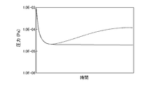
- FIG. 3 is a graph showing changes in pressure in the test body over time. According to this, as indicated by a dotted line in FIG. 3, the pressure indication value of the housing 1 continuously decreases to about 10 ⁇ 5 Pa and then increases again to about 10 ⁇ 4 Pa to reach equilibrium. confirmed. In this state, when only the grid voltage was changed from 150 V to 800 V, although a slightly lower pressure was indicated, it immediately increased to the original pressure. From this, it is considered that the cause of the pressure increase is not due to the grid 3.
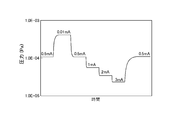
- the filament current and voltage from the power source E1 are appropriately controlled to change the emission current to 0.01 mA, 1 mA, 2 mA, 3 mA and 0.5 mA, respectively, every predetermined time, and the pressure in the test body over time is changed.
- Each measurement was performed, and the results are shown in FIG. According to this, it can be seen that the commanded pressure decreases as the emission current is increased.
- the pressure indication value of the housing 1 is around 10 ⁇ 5 Pa as shown by the solid line in FIG. It was confirmed that the water descended continuously until it reached equilibrium.
- the surface temperature of the ion collector 4 was measured when the emission current was changed by appropriately controlling the filament current and voltage from the power source E1, and the results are shown in FIG. According to this, even when the emission current was set to 10 mA, the temperature of the ion collector 4 was 250 ° C. or less, and the temperature of the housing 1 at that time was about 40 ° C. When the emission current was set to 10 mA, the supply power of the filament was 3.2W.
- the filament 2 is further heated by the increase of the emission current, the grid 3 and the ion collector 4 are heated and the temperature rises, and there is a possibility that the influence of the particles emitted from the surfaces thereof is reduced.
- the temperature of the ion collector 4 rising at this time is at most about plus 100 ° C.
- the temperature of the housing 1 is at most about plus 20 ° C., and there is no pressure fluctuation immediately after changing the emission current.
- the emission current is set to 2 mA or more, the amount of positive ions generated increases, and positive ions collide continuously even at both ends of the ion collector 4 where the collision probability of positive ions is low at a relatively low emission current.
- deposition as a weakly bonded molecular layer such as an oxide layer
- the triode ionization vacuum gauge IG (that is, the filament 2 and the grid 3) is configured so that a specified emission current can be obtained even when the supply power of the filament 2 is 4 W or less.
- other ammeter a 2 for measuring the emission current flowing between the filament 2 and the grid 3 to the negative output side of the power source E2 is provided, while measuring the pressure, power supply of the filaments 2 by the control unit Cu
- the power source E1 is controlled so that the emission current measured by the ammeter A2 is 4 W or less and is in the range of 2 mA to 10 mA.
- the amount of positive ions generated increases, and positive ions collide continuously at both ends of the ion collector 4 where the collision probability of positive ions is low at a relatively low emission current.
- Deposition as a weakly bound molecular layer (such as an oxide layer) is suppressed.
- the influence of particles emitted from the surface of the ion collector 4 in the high vacuum region is suppressed as much as possible when the pressure is measured by attaching to the measurement object, and the pressure of the measurement object is accurately measured. Can do. If the emission current is set to a value exceeding 10 mA, the power supplied to the filament exceeds 4 W, and the temperature of the vacuum partition also exceeds 50 ° C.
- the filament 2, the grid 3, and the ion collector 4 are housed in the metal housing 1, the charge-up of the thermoelectrons to the housing 1 is prevented, and the potential distribution in the space surrounded by the housing 1 is reduced. Always kept constant. As a result, the pressure can be measured with a constant sensitivity over a long period of time.
- the filament 22 has the apex 22a and the midpoint of the length of the ion collector 4 in the direction of the generatrix in the vicinity of the midpoint Mp of the grid 3 in the length of the generatrix.
- the present invention is not limited to this, and the position of the filament 2 with respect to the grid 3 is appropriately set upward or downward as long as the electron emission efficiency when energizing the filament 2 to emit thermal electrons does not decrease beyond a predetermined value. Can be shifted.
- the filament 2 for example, a straight shape or a coiled shape can be used. In this case, the region where the electron emission efficiency is high is the midpoint Mp of the length of the grid 3 in the generatrix direction. It arrange
- IG triode ionization vacuum gauge
- S sensor section
- C control unit
- 1 metal housing (vacuum partition wall)
- 2 filament
- 3 ... grid
- 4 ... ion collector
Landscapes
- Physics & Mathematics (AREA)
- General Physics & Mathematics (AREA)
- Measuring Fluid Pressure (AREA)
Abstract
Description
Claims (2)
- 測定対象物に装着されてその内部の圧力を検出する三極管型電離真空計であって、
フィラメントと、フィラメントの周囲に配置される筒状の輪郭を有するグリッドと、グリッドの周囲に同心に配置される筒状のイオンコレクタと、フィラメントに直流電流を通電してフィラメントを赤熱させるフィラメント点灯用の電源と、グリッドに対してフィラメントより高い電位をこのグリッドに与えるグリッド用の電源と、フィラメントの電位をイオンコレクタの電位よりも高くする電源とを備え、フィラメントへの供給電力を4W以下としたものにおいて、
フィラメントとグリッドとの間のエミッション電流を2mA~10mAの範囲となるように制御するように構成したことを特徴とする三極管型電離真空計。 - 前記フィラメントと、前記グリッドと、前記イオンコレクタとを金属製の真空隔壁内に収納したことを特徴とする請求項1記載の三極管型電離真空計。
Priority Applications (3)
| Application Number | Priority Date | Filing Date | Title |
|---|---|---|---|
| KR1020177030432A KR101982606B1 (ko) | 2015-03-23 | 2016-02-10 | 삼극관형 전리 진공계 |
| JP2017507357A JP6227836B2 (ja) | 2015-03-23 | 2016-02-10 | 三極管型電離真空計 |
| CN201680017058.4A CN107407612B (zh) | 2015-03-23 | 2016-02-10 | 三极管型电离真空计 |
Applications Claiming Priority (2)
| Application Number | Priority Date | Filing Date | Title |
|---|---|---|---|
| JP2015-059501 | 2015-03-23 | ||
| JP2015059501 | 2015-03-23 |
Publications (1)
| Publication Number | Publication Date |
|---|---|
| WO2016151997A1 true WO2016151997A1 (ja) | 2016-09-29 |
Family
ID=56978858
Family Applications (1)
| Application Number | Title | Priority Date | Filing Date |
|---|---|---|---|
| PCT/JP2016/000699 Ceased WO2016151997A1 (ja) | 2015-03-23 | 2016-02-10 | 三極管型電離真空計 |
Country Status (5)
| Country | Link |
|---|---|
| JP (1) | JP6227836B2 (ja) |
| KR (1) | KR101982606B1 (ja) |
| CN (1) | CN107407612B (ja) |
| TW (1) | TWI626435B (ja) |
| WO (1) | WO2016151997A1 (ja) |
Cited By (2)
| Publication number | Priority date | Publication date | Assignee | Title |
|---|---|---|---|---|
| KR20190006434A (ko) | 2017-07-10 | 2019-01-18 | 가부시키가이샤 아루박 | 삼극관형 전리 진공계 및 압력 측정 방법 |
| JP2021523361A (ja) * | 2018-05-09 | 2021-09-02 | エム ケー エス インストルメンツ インコーポレーテッドMks Instruments,Incorporated | 分圧検出装置及び方法 |
Families Citing this family (1)
| Publication number | Priority date | Publication date | Assignee | Title |
|---|---|---|---|---|
| JP3097706B2 (ja) | 1991-08-28 | 2000-10-10 | ブラザー工業株式会社 | 刺繍装置付きミシン |
Citations (1)
| Publication number | Priority date | Publication date | Assignee | Title |
|---|---|---|---|---|
| JP2013072694A (ja) * | 2011-09-27 | 2013-04-22 | Ulvac Japan Ltd | 熱陰極電離真空計 |
Family Cites Families (7)
| Publication number | Priority date | Publication date | Assignee | Title |
|---|---|---|---|---|
| JP3069975B2 (ja) * | 1991-09-06 | 2000-07-24 | アネルバ株式会社 | 電離真空計 |
| KR20010036738A (ko) * | 1999-10-11 | 2001-05-07 | 윤종용 | 진공 게이지 |
| KR20060131979A (ko) * | 2004-03-12 | 2006-12-20 | 브룩스 오토메이션, 인크. | 이온화 게이지 |
| CN100427912C (zh) * | 2006-03-31 | 2008-10-22 | 核工业西南物理研究院 | 具有高抗干扰能力的快响应电离真空计 |
| WO2009105506A1 (en) | 2008-02-21 | 2009-08-27 | Brooks Automation, Inc. | Ionization gauge with operational parameters and geometry designed for high pressure operation |
| EP2326931B1 (en) * | 2008-09-19 | 2019-04-24 | MKS Instruments, Inc. | Ionization gauge with emission current and bias potential control |
| US9593996B2 (en) * | 2012-02-08 | 2017-03-14 | Mks Instruments, Inc. | Ionization gauge for high pressure operation |
-
2016
- 2016-02-10 CN CN201680017058.4A patent/CN107407612B/zh active Active
- 2016-02-10 WO PCT/JP2016/000699 patent/WO2016151997A1/ja not_active Ceased
- 2016-02-10 JP JP2017507357A patent/JP6227836B2/ja active Active
- 2016-02-10 KR KR1020177030432A patent/KR101982606B1/ko active Active
- 2016-03-01 TW TW105106152A patent/TWI626435B/zh active
Patent Citations (1)
| Publication number | Priority date | Publication date | Assignee | Title |
|---|---|---|---|---|
| JP2013072694A (ja) * | 2011-09-27 | 2013-04-22 | Ulvac Japan Ltd | 熱陰極電離真空計 |
Cited By (9)
| Publication number | Priority date | Publication date | Assignee | Title |
|---|---|---|---|---|
| KR20190006434A (ko) | 2017-07-10 | 2019-01-18 | 가부시키가이샤 아루박 | 삼극관형 전리 진공계 및 압력 측정 방법 |
| CN109238559A (zh) * | 2017-07-10 | 2019-01-18 | 株式会社爱发科 | 三极管式电离真空计和压力测定方法 |
| JP2019015666A (ja) * | 2017-07-10 | 2019-01-31 | 株式会社アルバック | 三極管型電離真空計及び圧力測定方法 |
| TWI786129B (zh) * | 2017-07-10 | 2022-12-11 | 日商愛發科股份有限公司 | 三極管型電離真空計以及壓力測量方法 |
| KR102550943B1 (ko) * | 2017-07-10 | 2023-07-04 | 가부시키가이샤 아루박 | 삼극관형 전리 진공계 및 압력 측정 방법 |
| CN109238559B (zh) * | 2017-07-10 | 2025-01-14 | 株式会社爱发科 | 三极管式电离真空计和压力测定方法 |
| JP2021523361A (ja) * | 2018-05-09 | 2021-09-02 | エム ケー エス インストルメンツ インコーポレーテッドMks Instruments,Incorporated | 分圧検出装置及び方法 |
| JP2024051099A (ja) * | 2018-05-09 | 2024-04-10 | エム ケー エス インストルメンツ インコーポレーテッド | 分圧検出装置及び方法 |
| JP7628637B2 (ja) | 2018-05-09 | 2025-02-10 | エム ケー エス インストルメンツ インコーポレーテッド | 分圧検出装置及び方法 |
Also Published As
| Publication number | Publication date |
|---|---|
| KR20170129919A (ko) | 2017-11-27 |
| JPWO2016151997A1 (ja) | 2017-10-26 |
| KR101982606B1 (ko) | 2019-05-27 |
| TW201643397A (zh) | 2016-12-16 |
| CN107407612A (zh) | 2017-11-28 |
| JP6227836B2 (ja) | 2017-11-08 |
| TWI626435B (zh) | 2018-06-11 |
| CN107407612B (zh) | 2020-11-03 |
Similar Documents
| Publication | Publication Date | Title |
|---|---|---|
| JP5127042B2 (ja) | 電離真空計 | |
| US8169223B2 (en) | Ionization vacuum gauge | |
| US7332714B2 (en) | Quadrupole mass spectrometer and vacuum device using the same | |
| JP6227836B2 (ja) | 三極管型電離真空計 | |
| JP5669324B2 (ja) | 四重極型質量分析計 | |
| KR102550943B1 (ko) | 삼극관형 전리 진공계 및 압력 측정 방법 | |
| JP6803496B1 (ja) | 圧力測定方法及び熱陰極電離真空計 | |
| JP5827532B2 (ja) | 熱陰極電離真空計 | |
| CN104303033B (zh) | 用于高压操作的电离计 | |
| JP6227834B2 (ja) | 三極管型電離真空計 | |
| JP5783866B2 (ja) | 熱陰極電離真空計 | |
| JP2000039375A (ja) | イオン源 | |
| JP6200840B2 (ja) | 熱陰極電離真空計 | |
| JP4196367B2 (ja) | 電離真空計 | |
| JP2020118555A (ja) | 熱陰極電離真空計、熱陰極電離真空計を備える圧力測定システム並びに熱陰極電離真空計を用いた圧力測定方法 | |
| JP2010054518A (ja) | 複合型真空計 | |
| JP2002508836A (ja) | X−線効果を中和したバヤード−アルパート(bayard−alpert)型真空ゲージ | |
| JP2008128994A (ja) | 電離真空計及びこれを用いた質量分析計 | |
| JP2012234776A (ja) | 質量分析計用のイオン源及びこれを備えた質量分析計 |
Legal Events
| Date | Code | Title | Description |
|---|---|---|---|
| 121 | Ep: the epo has been informed by wipo that ep was designated in this application |
Ref document number: 16767910 Country of ref document: EP Kind code of ref document: A1 |
|
| ENP | Entry into the national phase |
Ref document number: 2017507357 Country of ref document: JP Kind code of ref document: A |
|
| NENP | Non-entry into the national phase |
Ref country code: DE |
|
| ENP | Entry into the national phase |
Ref document number: 20177030432 Country of ref document: KR Kind code of ref document: A |
|
| 122 | Ep: pct application non-entry in european phase |
Ref document number: 16767910 Country of ref document: EP Kind code of ref document: A1 |