WO2016148270A1 - 可搬型通信装置 - Google Patents
可搬型通信装置 Download PDFInfo
- Publication number
- WO2016148270A1 WO2016148270A1 PCT/JP2016/058646 JP2016058646W WO2016148270A1 WO 2016148270 A1 WO2016148270 A1 WO 2016148270A1 JP 2016058646 W JP2016058646 W JP 2016058646W WO 2016148270 A1 WO2016148270 A1 WO 2016148270A1
- Authority
- WO
- WIPO (PCT)
- Prior art keywords
- antenna
- communication device
- portable communication
- mechanical key
- circuit
- Prior art date
- Legal status (The legal status is an assumption and is not a legal conclusion. Google has not performed a legal analysis and makes no representation as to the accuracy of the status listed.)
- Ceased
Links
Images


Classifications
-
- H—ELECTRICITY
- H04—ELECTRIC COMMUNICATION TECHNIQUE
- H04B—TRANSMISSION
- H04B1/00—Details of transmission systems, not covered by a single one of groups H04B3/00 - H04B13/00; Details of transmission systems not characterised by the medium used for transmission
- H04B1/38—Transceivers, i.e. devices in which transmitter and receiver form a structural unit and in which at least one part is used for functions of transmitting and receiving
- H04B1/3822—Transceivers, i.e. devices in which transmitter and receiver form a structural unit and in which at least one part is used for functions of transmitting and receiving specially adapted for use in vehicles
-
- B—PERFORMING OPERATIONS; TRANSPORTING
- B60—VEHICLES IN GENERAL
- B60R—VEHICLES, VEHICLE FITTINGS, OR VEHICLE PARTS, NOT OTHERWISE PROVIDED FOR
- B60R25/00—Fittings or systems for preventing or indicating unauthorised use or theft of vehicles
- B60R25/01—Fittings or systems for preventing or indicating unauthorised use or theft of vehicles operating on vehicle systems or fittings, e.g. on doors, seats or windscreens
-
- B—PERFORMING OPERATIONS; TRANSPORTING
- B60—VEHICLES IN GENERAL
- B60R—VEHICLES, VEHICLE FITTINGS, OR VEHICLE PARTS, NOT OTHERWISE PROVIDED FOR
- B60R25/00—Fittings or systems for preventing or indicating unauthorised use or theft of vehicles
- B60R25/20—Means to switch the anti-theft system on or off
- B60R25/24—Means to switch the anti-theft system on or off using electronic identifiers containing a code not memorised by the user
- B60R25/241—Means to switch the anti-theft system on or off using electronic identifiers containing a code not memorised by the user whereby access privileges are related to the identifiers
-
- B—PERFORMING OPERATIONS; TRANSPORTING
- B60—VEHICLES IN GENERAL
- B60R—VEHICLES, VEHICLE FITTINGS, OR VEHICLE PARTS, NOT OTHERWISE PROVIDED FOR
- B60R25/00—Fittings or systems for preventing or indicating unauthorised use or theft of vehicles
- B60R25/20—Means to switch the anti-theft system on or off
- B60R25/24—Means to switch the anti-theft system on or off using electronic identifiers containing a code not memorised by the user
- B60R25/243—Means to switch the anti-theft system on or off using electronic identifiers containing a code not memorised by the user with more than one way to gain access
-
- E—FIXED CONSTRUCTIONS
- E05—LOCKS; KEYS; WINDOW OR DOOR FITTINGS; SAFES
- E05B—LOCKS; ACCESSORIES THEREFOR; HANDCUFFS
- E05B19/00—Keys; Accessories therefor
- E05B19/0082—Keys or shanks being removably stored in a larger object, e.g. a remote control or a key fob
-
- E—FIXED CONSTRUCTIONS
- E05—LOCKS; KEYS; WINDOW OR DOOR FITTINGS; SAFES
- E05B—LOCKS; ACCESSORIES THEREFOR; HANDCUFFS
- E05B49/00—Electric permutation locks; Circuits therefor ; Mechanical aspects of electronic locks; Mechanical keys therefor
- E05B49/002—Keys with mechanical characteristics, e.g. notches, perforations, opaque marks
-
- E—FIXED CONSTRUCTIONS
- E05—LOCKS; KEYS; WINDOW OR DOOR FITTINGS; SAFES
- E05B—LOCKS; ACCESSORIES THEREFOR; HANDCUFFS
- E05B81/00—Power-actuated vehicle locks
- E05B81/54—Electrical circuits
- E05B81/90—Manual override in case of power failure
-
- H—ELECTRICITY
- H04—ELECTRIC COMMUNICATION TECHNIQUE
- H04B—TRANSMISSION
- H04B1/00—Details of transmission systems, not covered by a single one of groups H04B3/00 - H04B13/00; Details of transmission systems not characterised by the medium used for transmission
- H04B1/02—Transmitters
- H04B1/04—Circuits
- H04B1/0458—Arrangements for matching and coupling between power amplifier and antenna or between amplifying stages
-
- H—ELECTRICITY
- H04—ELECTRIC COMMUNICATION TECHNIQUE
- H04B—TRANSMISSION
- H04B7/00—Radio transmission systems, i.e. using radiation field
- H04B7/02—Diversity systems; Multi-antenna system, i.e. transmission or reception using multiple antennas
- H04B7/04—Diversity systems; Multi-antenna system, i.e. transmission or reception using multiple antennas using two or more spaced independent antennas
- H04B7/06—Diversity systems; Multi-antenna system, i.e. transmission or reception using multiple antennas using two or more spaced independent antennas at the transmitting station
- H04B7/0602—Diversity systems; Multi-antenna system, i.e. transmission or reception using multiple antennas using two or more spaced independent antennas at the transmitting station using antenna switching
- H04B7/0608—Antenna selection according to transmission parameters
-
- H—ELECTRICITY
- H04—ELECTRIC COMMUNICATION TECHNIQUE
- H04B—TRANSMISSION
- H04B7/00—Radio transmission systems, i.e. using radiation field
- H04B7/02—Diversity systems; Multi-antenna system, i.e. transmission or reception using multiple antennas
- H04B7/10—Polarisation diversity; Directional diversity
-
- B—PERFORMING OPERATIONS; TRANSPORTING
- B60—VEHICLES IN GENERAL
- B60R—VEHICLES, VEHICLE FITTINGS, OR VEHICLE PARTS, NOT OTHERWISE PROVIDED FOR
- B60R25/00—Fittings or systems for preventing or indicating unauthorised use or theft of vehicles
- B60R25/20—Means to switch the anti-theft system on or off
- B60R25/24—Means to switch the anti-theft system on or off using electronic identifiers containing a code not memorised by the user
Definitions
- the present invention relates to a portable communication device that locks or unlocks a door of a vehicle by performing wireless communication with a communication device mounted on the vehicle.
- This system is a system that can be called by a name such as a so-called keyless entry system or smart entry system.
- Some portable communication devices possessed by a user in such a system include a mechanical key for locking or unlocking a door of a vehicle when, for example, a failure or a battery runs out.
- Patent Document 1 describes a portable device that has a transmission / reception circuit that transmits and receives a radio signal via an antenna, and that stores an emergency mechanical key in a storage portion in a removable manner.
- the portable device described in Patent Document 1 corrects the directivity of a radio signal by controlling a push switch that detects whether or not a mechanical key is stored in the storage unit and an antenna switch according to whether or not the mechanical key is stored.
- Patent Document 2 discloses an impedance matching circuit that adjusts the impedance between an antenna and a transmission / reception circuit and a control device that controls the impedance matching circuit according to whether or not the mechanical key is stored in a portable device having the same configuration. The configuration provided is described.
- the present invention has been made in view of such circumstances, and an object of the present invention is to provide a portable communication device capable of suppressing deterioration in communication efficiency due to downsizing of the device.
- a portable communication device is a portable communication device that performs wireless communication with a vehicle and locks or unlocks a door of the vehicle, and an antenna that transmits or receives a wireless signal;
- a key made of a conductor that mechanically locks or unlocks the door, and a connection portion that electrically connects the antenna and the key are provided.
- the portable communication device includes a housing in which the antenna is built in, and a storage portion that is provided in the housing and stores the key, and the connection portion is provided in the storage portion. When the key is stored, the antenna and the key are electrically connected.
- the portable communication device includes a communication circuit that transmits or receives a radio signal via the antenna, a detection unit that detects a storage state of the key in the storage unit, and a And a correction unit that corrects the impedance of the communication circuit according to a detection result.
- the portable communication device includes a detection unit that detects a storage state of the key in the storage unit, and a correction unit that corrects the directivity of the antenna according to a detection result of the detection unit. It is characterized by providing.
- the portable communication device is characterized in that the antenna is a loop antenna for radio signal transmission.
- the portable communication device includes a key for mechanically locking or unlocking the door of the vehicle, and the key is made of a conductor such as metal.
- the portable communication device includes an antenna for transmitting or receiving a radio signal, for example, a loop antenna for transmitting a radio signal.
- the portable communication device is configured to be able to electrically connect this antenna and a conductor key.
- the housing portion is provided in the housing with the built-in antenna, and the conductor key can be housed in the housing portion.
- the user mechanically locks or unlocks the door, the user takes out the conductor key stored in the storage unit and inserts it into the keyhole provided in the door of the vehicle to perform the operation of locking or unlocking. It can be carried out.
- the non-retracted key may be configured to be removable from the casing, for example, and is provided so as not to be removable from the casing, for example, when the user performs an operation such as turning or sliding.
- the structure which can make a key protrude from an accommodating part may be sufficient, and structures other than these may be sufficient.
- the portable communication device is configured to electrically connect the antenna and the key in a state where the key is stored in the storage unit.
- the antenna and the key are not electrically connected. For this reason, the substantial size of the antenna changes depending on whether or not the key is stored in the storage unit, and the communication characteristics related to wireless communication change. Therefore, by detecting the storage state of the key in the storage unit and performing the correction of the impedance of the communication circuit or the correction of the directivity of the antenna, etc. according to the detection result, the wireless suitable for the substantial antenna size is obtained. Communication can be performed.
- the portable communication device since the antenna can be substantially enlarged by electrically connecting the antenna for wireless communication and the key made of a conductor, the portable communication device is small. Can also prevent the communication efficiency from deteriorating.
- FIG. 1 It is a schematic diagram for demonstrating the structure of the portable communication apparatus which concerns on this Embodiment. It is a schematic diagram for demonstrating the structure of the portable communication apparatus which concerns on this Embodiment. It is a block diagram which shows the structure of the communication circuit of a portable communication apparatus. It is a circuit diagram which shows one structural example of an impedance matching circuit. It is a flowchart which shows the procedure of the process which a portable communication apparatus performs. It is a block diagram which shows the structure of the communication circuit 113 of the portable communication apparatus which concerns on the modification 1. FIG. It is a schematic diagram for demonstrating the structure of the portable communication apparatus which concerns on the modification 2. FIG. It is a schematic diagram for demonstrating the structure of the portable communication apparatus which concerns on the modification 2. FIG.
- a portable communication device 10 according to the present embodiment performs wireless communication with an in-vehicle communication device 2 provided in a vehicle 1.
- the portable communication device 10 can lock or unlock the door of the vehicle 1 by wireless communication with the in-vehicle communication device 2. That is, the portable communication device 10 according to the present embodiment is used in a so-called keyless entry system or smart entry system, and can be called by a name such as a wireless key or a remote control key.
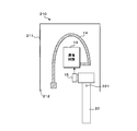
- the portable communication device 10 includes, for example, a substantially rectangular parallelepiped casing 11, and a communication circuit 13 and an antenna 14 are accommodated in the casing 11.
- the housing 11 is provided with a storage portion 12 for removably storing the mechanical key 20.
- the accommodating part 12 can be made into the recessed part which can insert the mechanical key 20 from the opening provided in the side surface of the housing
- the push switch 15 is disposed at the innermost part of the storage unit 12.
- the tip of the mechanical key 20 pushes (presses) the push switch 15.
- a signal indicating the state of the push switch 15 is input to the communication circuit 13.
- the communication circuit 13 is a circuit that performs processing such as modulation and demodulation for wireless communication.
- the communication circuit 13 is configured by arranging a plurality of circuit elements on a circuit board.
- the communication circuit 13 is connected to a transmission antenna 14 for transmitting a radio signal.
- the transmitting antenna 14 is a loop antenna in which a conductor such as metal is arranged in an arc shape or an annular shape.
- One end of the transmitting antenna 14 is connected to the communication circuit 13.
- the other end of the transmitting antenna 14 is disposed on, for example, the inner peripheral surface of the storage portion 12, and serves as a connection portion 14 a for electrical connection with the mechanical key 20.
- the mechanical key 20 is in contact with the connecting portion 14a of the transmitting antenna 14 in the state of being stored in the storing portion 12, and the transmitting antenna 14 and the mechanical key 20 are electrically connected. In this state, the mechanical key 20 serves as a transmitting antenna.
- the storage unit 36 is configured using a non-volatile memory element such as an EEPROM (Electrically Erasable Programmable Read Only Memory).
- the storage unit 36 stores information such as identification information or authentication information attached in advance to the portable communication device 10.
- the control part 31 reads the information memorize
- the in-vehicle communication device 2 can determine whether the portable communication device 10 that is the transmission source of the wireless signal is valid by determining whether the information included in the received wireless signal is correct.
- the operation unit 37 is configured using, for example, a push-type button, and a user performs a push operation or the like.
- the operation unit 37 may be configured to include two buttons, a push button for locking the door of the vehicle 1 and a push button for unlocking. Further, for example, the operation unit 37 may alternately lock and unlock the door of the vehicle 1 by repeatedly operating one push button.
- the operation unit 37 may be other than a push button, for example, a slide switch or a touch panel.
- the impedance matching circuit 35 corrects the impedance between the transmission circuit 34 and the transmission antenna 14 in accordance with the control of the control unit 31, and transmits and receives radio signals between the portable communication device 10 and the in-vehicle communication device 2. It is a circuit to optimize.
- the impedance matching circuit 35 can be configured as an LC circuit using a coil and a capacitor, for example.
- the control unit 31 outputs a control signal to the impedance matching circuit 35 according to the state of the push switch 15, that is, whether or not the mechanical key 20 is stored in the storage unit 12.
- FIG. 4 is a circuit diagram showing a configuration example of the impedance matching circuit 35.
- the impedance matching circuit 35 includes a first circuit 35a configured using the coil L1 and the capacitor C1, a second circuit 35b configured using the coil L2 and the capacitor C2, a transmission circuit 34, and a transmission circuit. Switches SW1 and SW2 are provided for switching whether the first circuit 35a or the second circuit 35b is interposed between the trusted antennas 14.
- the coil L1 is disposed in the signal transmission path between the transmission circuit 34 and the transmission antenna 14, and one end of the capacitor C1 is connected to the end of the coil L1 on the transmission antenna 14 side. The other end is connected to the ground potential.
- the second circuit 35b has a circuit configuration similar to that of the first circuit 35a, but the inductance of the coil L2 and the capacitance of the capacitor C2 are different from those of the coil L1 and the capacitor C2 of the first circuit 35a.
- the inductance of the coil L1 and the capacitance of the capacitor C1 of the first circuit 35a are set to values that can optimize wireless communication in a state where the transmitting antenna 14 and the mechanical key 20 are electrically connected.
- the inductance of the coil L2 and the capacitance of the capacitor C2 of the second circuit 35b are set to values that can optimize wireless communication in a state where the mechanical key 20 is not connected to the transmitting antenna 14.
- the control unit 31 switches the switches SW1 and SW2 to the first circuit 35a side when the mechanical key 20 is stored in the storage unit 12 according to the state of the push switch 15. As a result, the first circuit 35 a is selected in the impedance matching circuit 35, and the first circuit 35 a is interposed between the transmission circuit 34 and the transmission antenna 14. Further, when the mechanical key 20 is not stored in the storage unit 12, the control unit 31 switches the switches SW1 and SW2 to the second circuit 35b side. As a result, the second circuit 35 b is selected in the impedance matching circuit 35, and the second circuit 35 b is interposed between the transmission circuit 34 and the transmission antenna 14.
- FIG. 5 is a flowchart showing a procedure of processing performed by the portable communication device 10.
- the control unit 31 of the portable communication device 10 determines whether or not an operation has been performed on the operation unit 37 (step S1). When the operation is not performed (S1: NO), the control unit 31 waits until the operation is performed. When an operation is performed (S1: YES), the control unit 31 determines whether the mechanical key 20 is stored in the storage unit 12 based on a signal input from the push switch 15 (step S2). When the mechanical key 20 is housed (S2: YES), the control unit 31 selects the first circuit 35a by performing switching control of the switches SW1 and SW2 of the impedance matching circuit 35 (step S3).
- the portable communication device 10 includes a mechanical key 20 for mechanically locking or unlocking the door of the vehicle 1.
- the mechanical key 20 is made of a conductor such as metal.
- the portable communication device 10 includes a transmission antenna 14 for transmitting a radio signal.
- the transmitting antenna 14 can be a loop antenna, for example.
- the portable communication device 10 has a configuration capable of electrically connecting the transmitting antenna 14 and the mechanical key 20. Thereby, since the mechanical key 20 can be used as an additional antenna, the transmission antenna 14 can be substantially enlarged, and communication efficiency can be improved.
- the portable communication device 10 is configured such that the storage unit 12 is provided in the housing 11 in which the transmission antenna 14 is built, and the mechanical key 20 can be stored in the storage unit.
- the user mechanically locks or unlocks the door of the vehicle 1
- the user takes out the mechanical key 20 stored in the storage unit 12 and inserts it into the keyhole provided in the door of the vehicle 1 to lock or unlock the vehicle 1. Can be operated.
- the transmission antenna 14 and the mechanical key 20 are electrically connected.
- the portable communication device 10 detects the storage state of the mechanical key 20 in the storage unit 12 by the push switch 15 and performs the impedance correction of the communication circuit 13 according to the detection result by the impedance matching circuit 35. Thereby, with respect to a change in communication characteristics due to a substantial change in the size of the transmitting antenna 14 due to the presence or absence of the mechanical key 20, it is possible to perform appropriate wireless communication by correcting the influence of this change.
- the portable communication device 10 is configured to transmit and receive wireless signals to and from the in-vehicle communication device 2, but the present invention is not limited to this, and either wireless signal transmission or reception is possible. It may be configured to perform only one.
- the mechanical key 20 is electrically connected to the transmitting antenna 14, the present invention is not limited to this, and the mechanical key 20 may be electrically connected to the receiving antenna 33.
- the transmitting and receiving antennas may be a single antenna.
- the portable communication apparatus 10 is configured to transmit a wireless signal in response to an operation on the operation unit 37, the present invention is not limited to this. For example, when the portable communication device 10 receives a wireless signal from the in-vehicle communication device 2, the portable communication device 10 may be configured to transmit a wireless signal as a response.
- the push switch 15 detects whether or not the mechanical key 20 is stored in the storage unit 12, the present invention is not limited to this, and the detection may be performed by other methods.
- the configuration of the impedance matching circuit 35 shown in FIG. 4 is an example, and the present invention is not limited to this.
- FIG. 6 is a block diagram illustrating a configuration of the communication circuit 113 of the portable communication device 110 according to the first modification.
- the portable communication device 110 according to the first modification is configured to correct the directivity of the transmitting antenna 14 depending on whether or not the mechanical key 20 is housed.
- a portable communication device 110 according to Modification 1 includes a directivity correction unit 135 instead of the impedance matching circuit 35 of the portable communication device 10 illustrated in FIG. 3, and includes a first antenna 114 a and a first antenna as a transmission antenna. Two antennas 114b are provided.
- the directivity correction unit 135 corrects the directivity of the transmission antenna by connecting either the first antenna 114 a or the second antenna 114 b to the transmission circuit 34 under the control of the control unit 31.
- the first antenna 114 a is an antenna that is electrically connected to the mechanical key 20 housed in the housing portion 12 and designed to obtain optimum directivity in this state.
- the second antenna 114 b is an antenna that is designed so that optimum directivity is obtained in a state where the mechanical key 20 is not housed in the housing portion 12 without being electrically connected to the mechanical key 20.
- the control unit 31 determines whether or not the mechanical key 20 is stored in the storage unit 12 by the push switch 15. When the mechanical key 20 is stored, the control unit 31 performs control so that the directivity correction unit 135 selects the first antenna 114a. When the mechanical key 20 is not stored, the control unit 31 performs control so that the directivity correction unit 135 selects the second antenna 114b.
- the portable communication device 110 detects the storage state of the mechanical key 20 in the storage unit 12 by the push switch 15, and corrects the directivity of the transmitting antenna according to the detection result. Is performed by the directivity correction unit 135. Thereby, with respect to a change in directivity due to a substantial change in the size of the transmitting antenna 14 due to the presence or absence of the mechanical key 20, it is possible to correct the influence of this change and perform appropriate wireless communication.
- the portable communication device may be configured to include both the impedance matching circuit 35 illustrated in FIG. 3 and the directivity correction 135 illustrated in FIG. 6.
- the first antenna 114a is connected to the first circuit 35a
- the second antenna 114b is connected to the second circuit 35b
- the control unit 31 switches the switch SW1. be able to.
- the portable communication device 210 according to the modified example 2 has a configuration in which an opening is provided on one side surface of a substantially rectangular parallelepiped casing 211 and the mechanical key 20 enters and exits the casing 211 through the opening. That is, the vicinity of the side surface at the position in the housing 211 is the storage portion 212 of the mechanical key 20.
- the mechanical key 20 is fixed to the housing 211 by a rotation shaft 221 so as to be rotatable.
- the user rotates the mechanical key 20 about 90 degrees around the rotation shaft 221 to expose the mechanical key 20 stored in the housing 211 to the outside, thereby mechanically locking the door of the vehicle 1 or
- the unlocking operation can be performed with the mechanical key 20.
- 7 shows a state in which the mechanical key 20 is stored in the storage unit 212
- FIG. 8 shows a state in which the mechanical key 20 is exposed.
- the communication circuit 13, the transmission antenna 14, the push switch 15, and the like are accommodated.
- One end of the transmitting antenna 14 is connected to the communication circuit 13.
- the other end of the transmitting antenna 14 is disposed on the inner surface of the housing portion 212 of the housing 211, and serves as a connection portion 14a for electrical connection with the mechanical key 20.
- the mechanical key 20 is in contact with the connecting portion 14a of the transmitting antenna 14 while being stored in the storing portion 212, and the transmitting antenna 14 and the mechanical key 20 are electrically connected. In this state, the mechanical key 20 serves as a transmitting antenna.
- the push switch 15 is not pushed when the mechanical key 20 is housed in the housing portion 212, and when the mechanical key 20 is rotated approximately 90 degrees from the housed state and exposed to the outside of the housing 211, the push switch 15 It is arranged at a position to be pushed by the end side surface or the like. A signal indicating the state of the push switch 15 is input to the communication circuit 13.
- the processing performed by the communication circuit 13 is substantially the same as the processing performed by the communication circuit 13 of the portable communication device 10 according to the above-described embodiment.
- the communication circuit 13 performs a process of controlling the impedance matching circuit 35 according to the state of the push switch 15, that is, whether or not the mechanical key 20 is housed. Further, for example, the communication circuit 13 performs a transmission process of a radio signal to the in-vehicle communication device 2 and a reception process of a radio signal from the in-vehicle communication device 2.
- the storage of the mechanical key 20 of the portable communication device can be realized with various structures, other than the structures shown in FIGS. It may be adopted.
- the transmitting antenna 14 and the mechanical key 20 may be always connected.
- the impedance and directivity need not necessarily be corrected, but may be corrected when the impedance and directivity change due to a change in the position of the mechanical key 20.
Landscapes
- Engineering & Computer Science (AREA)
- Computer Networks & Wireless Communication (AREA)
- Signal Processing (AREA)
- Mechanical Engineering (AREA)
- Lock And Its Accessories (AREA)
- Transceivers (AREA)
- Transmitters (AREA)
- Radio Transmission System (AREA)
Priority Applications (1)
| Application Number | Priority Date | Filing Date | Title |
|---|---|---|---|
| US15/557,175 US9973227B2 (en) | 2015-03-19 | 2016-03-18 | Portable communication device |
Applications Claiming Priority (2)
| Application Number | Priority Date | Filing Date | Title |
|---|---|---|---|
| JP2015056477A JP2016178444A (ja) | 2015-03-19 | 2015-03-19 | 可搬型通信装置 |
| JP2015-056477 | 2015-03-19 |
Publications (1)
| Publication Number | Publication Date |
|---|---|
| WO2016148270A1 true WO2016148270A1 (ja) | 2016-09-22 |
Family
ID=56918824
Family Applications (1)
| Application Number | Title | Priority Date | Filing Date |
|---|---|---|---|
| PCT/JP2016/058646 Ceased WO2016148270A1 (ja) | 2015-03-19 | 2016-03-18 | 可搬型通信装置 |
Country Status (3)
| Country | Link |
|---|---|
| US (1) | US9973227B2 (https=) |
| JP (1) | JP2016178444A (https=) |
| WO (1) | WO2016148270A1 (https=) |
Families Citing this family (1)
| Publication number | Priority date | Publication date | Assignee | Title |
|---|---|---|---|---|
| JP6693448B2 (ja) | 2017-03-13 | 2020-05-13 | トヨタ自動車株式会社 | 車両制御システム、車両制御システムにおける車両制御方法、携帯機、携帯機の制御方法、車両側制御部、及び、車両側制御部の制御方法 |
Citations (3)
| Publication number | Priority date | Publication date | Assignee | Title |
|---|---|---|---|---|
| JP2008045272A (ja) * | 2006-08-10 | 2008-02-28 | Tokai Rika Co Ltd | キーレスエントリー送信機 |
| JP2009177642A (ja) * | 2008-01-25 | 2009-08-06 | Tokai Rika Co Ltd | 携帯機及びインピーダンス補正方法 |
| JP2009177644A (ja) * | 2008-01-25 | 2009-08-06 | Tokai Rika Co Ltd | 携帯機及び指向性補正方法 |
Family Cites Families (2)
| Publication number | Priority date | Publication date | Assignee | Title |
|---|---|---|---|---|
| JP2017203314A (ja) * | 2016-05-12 | 2017-11-16 | トヨタ自動車株式会社 | 無線通信システム |
| DE102016217318A1 (de) * | 2016-07-26 | 2018-02-01 | Volkswagen Aktiengesellschaft | Verfahren, Computerprogramm und Vorrichtung zum Überprüfen einer Berechtigung eines mobilen Kommunikationsgeräts |
-
2015
- 2015-03-19 JP JP2015056477A patent/JP2016178444A/ja active Pending
-
2016
- 2016-03-18 WO PCT/JP2016/058646 patent/WO2016148270A1/ja not_active Ceased
- 2016-03-18 US US15/557,175 patent/US9973227B2/en active Active
Patent Citations (3)
| Publication number | Priority date | Publication date | Assignee | Title |
|---|---|---|---|---|
| JP2008045272A (ja) * | 2006-08-10 | 2008-02-28 | Tokai Rika Co Ltd | キーレスエントリー送信機 |
| JP2009177642A (ja) * | 2008-01-25 | 2009-08-06 | Tokai Rika Co Ltd | 携帯機及びインピーダンス補正方法 |
| JP2009177644A (ja) * | 2008-01-25 | 2009-08-06 | Tokai Rika Co Ltd | 携帯機及び指向性補正方法 |
Also Published As
| Publication number | Publication date |
|---|---|
| JP2016178444A (ja) | 2016-10-06 |
| US20180076838A1 (en) | 2018-03-15 |
| US9973227B2 (en) | 2018-05-15 |
Similar Documents
| Publication | Publication Date | Title |
|---|---|---|
| JP6681477B2 (ja) | 近距離無線通信タグ | |
| US11913254B2 (en) | Electro-mechanical lock core | |
| JP5175782B2 (ja) | 遠隔制御システム、および携帯機 | |
| US20180138966A1 (en) | Vehicle-mounted communication apparatus | |
| JP2015030381A (ja) | 車両制御システム、携帯機、及び車載機 | |
| WO2016148270A1 (ja) | 可搬型通信装置 | |
| WO2021131713A9 (ja) | 車両のスマートキー収納ケース | |
| JP4999973B2 (ja) | 無線通信システム | |
| US10773686B2 (en) | Card-type vehicle smart key and control method therefor | |
| JP2009177644A (ja) | 携帯機及び指向性補正方法 | |
| JP2009177642A (ja) | 携帯機及びインピーダンス補正方法 | |
| JP2009177643A (ja) | 携帯機及び通信効率補正方法 | |
| US20070139157A1 (en) | On-vehicle radio device | |
| JP6569862B2 (ja) | アンテナ出力調整装置 | |
| JP2008174960A (ja) | 車両のキーレスシステム | |
| JP2006083514A (ja) | 車両ドアのキーレス制御システム | |
| US20170161974A1 (en) | Method of preventing hacking of wireless signals | |
| EP3038071B1 (en) | Identification device for a remote control arrangement of a vehicle and remote control arrangement for a vehicle | |
| US20170103596A1 (en) | Wireless access control system including lock assembly operating in automatic calibration mode and related methods | |
| JP5526871B2 (ja) | 受信装置 | |
| JP5169759B2 (ja) | 触手検出装置および車両制御システム | |
| JP5689865B2 (ja) | 制御装置 | |
| JP2010081506A (ja) | 受信装置及びこれを用いた通信システム | |
| JP2007284955A (ja) | 遠隔制御用携帯機ホルダ | |
| JP2007262793A (ja) | 建物用施解錠システムにおける通信中継装置 |
Legal Events
| Date | Code | Title | Description |
|---|---|---|---|
| 121 | Ep: the epo has been informed by wipo that ep was designated in this application |
Ref document number: 16765099 Country of ref document: EP Kind code of ref document: A1 |
|
| NENP | Non-entry into the national phase |
Ref country code: DE |
|
| WWE | Wipo information: entry into national phase |
Ref document number: 15557175 Country of ref document: US |
|
| 122 | Ep: pct application non-entry in european phase |
Ref document number: 16765099 Country of ref document: EP Kind code of ref document: A1 |