WO2016147983A1 - 摩擦撹拌接合装置 - Google Patents
摩擦撹拌接合装置 Download PDFInfo
- Publication number
- WO2016147983A1 WO2016147983A1 PCT/JP2016/057403 JP2016057403W WO2016147983A1 WO 2016147983 A1 WO2016147983 A1 WO 2016147983A1 JP 2016057403 W JP2016057403 W JP 2016057403W WO 2016147983 A1 WO2016147983 A1 WO 2016147983A1
- Authority
- WO
- WIPO (PCT)
- Prior art keywords
- friction stir
- stir welding
- workpiece
- work
- axis direction
- Prior art date
- Legal status (The legal status is an assumption and is not a legal conclusion. Google has not performed a legal analysis and makes no representation as to the accuracy of the status listed.)
- Ceased
Links
Images




Classifications
-
- B—PERFORMING OPERATIONS; TRANSPORTING
- B23—MACHINE TOOLS; METAL-WORKING NOT OTHERWISE PROVIDED FOR
- B23K—SOLDERING OR UNSOLDERING; WELDING; CLADDING OR PLATING BY SOLDERING OR WELDING; CUTTING BY APPLYING HEAT LOCALLY, e.g. FLAME CUTTING; WORKING BY LASER BEAM
- B23K20/00—Non-electric welding by applying impact or other pressure, with or without the application of heat, e.g. cladding or plating
- B23K20/12—Non-electric welding by applying impact or other pressure, with or without the application of heat, e.g. cladding or plating the heat being generated by friction; Friction welding
Definitions
- the present disclosure relates to a friction stir welding apparatus used for friction stir welding at a joint between workpieces.
- This application claims priority based on Japanese Patent Application No. 2015-054606 for which it applied to Japan on March 18, 2015, and uses the content here.
- the friction stir welding tool (friction stir welding tool) used in the friction stir welding apparatus includes a type having a rotary shoulder that rotates integrally with the probe, and a rotating probe and a non-rotating fixed shoulder.
- the format is known.
- the fixed shoulder abuts against the surfaces of both workpieces forming the corner corners in order to friction stir weld the corners (inner corners) of the workpieces to be joined.
- a shape with a surface is known.
- This friction stir welding apparatus has a gate-shaped frame (gate pillar) arranged so as to straddle the workpiece.
- the second work is erected on the first work by pressing the second work to be erected from above and pressing it against the horizontal first work by the pressing mechanism provided on the frame. Maintain the bonding posture.
- the pair of friction stir welding tools are pressed against the corners between the workpieces by another pressing mechanism provided on the frame, and the corners are friction stir welded.
- AdStir is designed to form a curved surface (fillet fillet) in the corner corner after joining when performing friction stir welding at the corner corner by a friction stir welding tool equipped with a fixed shoulder.
- a technique called “Non-Patent Document 1” has also been proposed in the past.
- the accuracy of the joining posture of the standing second workpiece held by the posture holding pressing mechanism is affected by the reaction force of the pressing load of the friction stir welding tool.
- Non-Patent Document 1 does not particularly show a means for maintaining the joining posture of the workpiece formed with the corner corners to be joined at the time of friction stir welding.
- the present disclosure provides a friction stirrer capable of friction stir welding a joint between workpieces while maintaining the joining posture of the workpieces to be joined in a state not affected by the reaction force of the pressing load of the friction stir welding tool.
- An object is to provide a joining device.
- a friction stir welding apparatus is formed separately from a joining apparatus body including a friction stir welding tool that friction stir welds joints between a plurality of workpieces that are in contact with each other, and the joining apparatus body.
- a work clamp unit having a rolling element configured to hold the work when performing friction stir welding of the joint.
- the joint between the workpieces is friction stir while maintaining the joining posture of the workpieces to be joined in a state not affected by the reaction force of the pressing load of the friction stir welding tool. Can be joined.
- FIG. 2 is an AA arrow view of FIG. It is a top view which expands and shows the part of the friction stir welding tool of the friction stir welding apparatus of 1st Embodiment. It is a BB direction arrow line view of FIG. 4A. It is the enlarged view which looked at the joining apparatus main body of the friction stir welding apparatus of 1st Embodiment along the direction to which a workpiece
- FIG. 7 is a view in the direction of arrows CC in FIG. 6. It is a top view which expands and shows the work table of the work holding part of the friction stir welding apparatus of 1st Embodiment. It is a side view which expands and shows the work table of the workpiece
- FIG. 6 is a partial cutaway view showing an axis-orthogonal direction moving unit in a tool pressing portion of the joining apparatus main body of FIG. 5. It is a DD direction arrow line view of FIG. FIG.
- FIG. 6 is a partial cutaway view showing an axial movement unit in a tool pressing portion of the joining apparatus main body of FIG. 5.
- FIG. 13 is a view taken in the direction of arrows EE in FIG. 12. It is a figure which shows the work clamp unit of the friction stir welding apparatus of 2nd Embodiment.
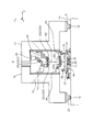
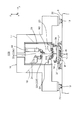
- FIG. 1 is a schematic side view showing the friction stir welding apparatus according to the first embodiment.
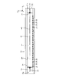
- 2 is a schematic plan view of FIG. 1
- FIG. 3 is a view taken in the direction of arrows AA in FIG. 4A is an enlarged plan view showing a portion of the friction stir welding tool
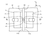
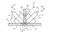
- FIG. 4B is a BB direction view of FIG. 4A.
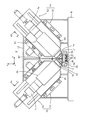
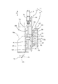
- FIG. 5 is an enlarged view of the joining apparatus main body according to the first embodiment viewed along the direction in which the workpiece moves during friction stir welding.
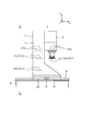
- FIG. 6 is an enlarged side view showing the work clamp unit in the first embodiment.
- FIG. 7 is a view in the direction of arrows CC in FIG.
- FIG. 8A is an enlarged plan view showing the work table in the first embodiment, and FIG.
- FIG. 8B is an enlarged side view showing the work table.
- FIG. 9 is a schematic plan view showing a table moving path in the first embodiment.
- FIG. 10 is a partial cutaway view showing the axis-orthogonal direction moving unit in the tool pressing portion of the joining apparatus main body.
- FIG. 11 is a view in the DD direction of FIG.
- FIG. 12 is a partial cutaway view showing the axial movement unit in the tool pressing portion of the joining apparatus main body.
- 13 is a view taken in the direction of arrows EE in FIG.
- the friction stir welding apparatus has a second end whose end edge is abutted in a posture that intersects the first workpiece W1 and the surface P1 of the first workpiece W1 at a predetermined angle.
- Two corners (inner corners) c1 and c2 formed by the workpiece W2 are subject to friction stir welding.
- the surface P1 of the first workpiece W1 is horizontally disposed, and the second workpiece W2 is abutted from above with the surface P1 of the first workpiece W1 in a vertical posture. Will be described.
- the direction in which the corner portions c1 and c2 extend is the x-axis direction
- the direction parallel to the surface P1 of the first workpiece W1 in the plane perpendicular to the x-axis direction is the y-axis direction
- the x-axis direction is the x-axis direction
- a three-dimensional orthogonal coordinate system is set in which the direction orthogonal to both the y-axis directions is the z-axis direction.
- the xy plane along the plane P1 of the first workpiece W1 is a horizontal plane
- the z-axis direction is the vertical direction
- the second workpiece W2 is arranged along the xz plane, which is a vertical plane.
- the xy plane indicates a plane along the x-axis direction and the y-axis direction
- the xz plane indicates a plane along the x-axis direction and the z-axis direction
- the yz plane indicates the y-axis direction and the z-axis direction.
- the plane along is shown.
- the xy plane, the xz plane, and the yz plane do not mean a plane whose position is specified.
- the friction stir welding apparatus joins the joining apparatus main body 5 placed on the surface of the gantry 8, the first work W1, and the second work W2 as described above.
- a work table 10 arranged in a posture, a table moving path 11 (see FIG. 7) for guiding movement of the work table 10 in the x-axis direction on the surface of the gantry 8, and a moving mechanism 12 of the work table 10 are provided.
- the friction stir welding apparatus according to the present embodiment includes a work clamp unit 9 formed separately from the bonding apparatus main body 5.
- the friction stir welding apparatus As shown in FIGS. 1 to 3, the friction stir welding apparatus according to the present embodiment is provided with a joining apparatus main body 5 including friction stir welding tools 1 a and 1 b on a base 8, and a workpiece W ⁇ b> 1 with respect to the joining apparatus main body 5.
- W2 are moved in one direction along the x-axis direction as indicated by an arrow w in FIGS.
- the friction stir welding tools 1a and 1b move relative to the corners c1 and c2 as the workpieces W1 and W2 move to perform friction stir welding.
- the work clamp unit 9 is disposed on the front side (the left side in FIGS. 1 and 2) in the tool relative movement direction t with respect to the joining apparatus body 5.
- the tool relative movement direction t is a direction in which the friction stir welding tools 1a and 1b and the welding apparatus main body 5 relatively move with respect to the corners c1 and c2 when performing friction stir welding.
- the tool relative movement direction t is opposite to the actual movement direction of the workpieces W1 and W2 (the direction indicated by the arrow w).
- the joining apparatus main body 5 of the present embodiment is used to join the corner portion c1 on the side surface P2a side of the second workpiece W2 out of the two corner portions c1 and c2.
- the first friction stir welding tool 1a to be used and the second friction stir welding tool 1b to be used for joining the corner portion c2 on the other side surface P2b side are provided.
- the first friction stir welding tool 1a includes a probe 2a that can be driven to rotate, and a fixed shoulder 3a disposed on the outer periphery of the proximal end side of the probe 2a.
- the probe 2a is preferably arranged so that the axial center direction of the probe 2a is parallel to the bisector of the angle of the corner portion c1 in the yz plane.
- the corner c1 is a right angle
- the axial center direction of the probe 2a is 45 degrees from the z-axis direction (vertical direction) along the second workpiece W2 in the yz plane to the side surface P2a side. It is arranged so as to form an inclined obliquely downward angle.
- the fixed shoulder 3a has two end portions arranged near the tip of the probe 2a, which are in contact with the surface P1 of the first workpiece W1 and the side surface P2a of the second workpiece W2 forming the corner portion c1, respectively. It is a mountain shape (V shape) provided with the workpiece contact surface 4a.
- the first friction stir welding tool 1 a is attached to the distal end side of the first main spindle unit 6 a provided with a rotation drive unit 7 a that rotationally drives the probe 2 a in the bonding apparatus body 5. Used in state.
- the second friction stir welding tool 1b includes a probe 2b that can be driven to rotate, and a fixed shoulder 3b that is disposed on the outer periphery of the proximal end side of the probe 2b.
- the probe 2b is preferably disposed so that the axial center direction of the probe 2b is parallel to the bisector of the angle of the corner portion c2 in the yz plane.
- the corner c2 is a right angle
- the axial center direction of the probe 2b is 45 degrees from the z-axis direction (vertical direction) along the second workpiece W2 to the other side surface P2b side in the yz plane.
- the fixed shoulder 3b has two end portions arranged near the tip of the probe 2b, which are in contact with the surface P1 of the first workpiece W1 and the side surface P2b of the second workpiece W2 that form the corner portion c2. It is a mountain shape (V shape) provided with the workpiece contact surface 4b.
- the second friction stir welding tool 1 b is attached to the distal end side of the second main spindle unit 6 b provided with a rotation drive unit 7 b that rotationally drives the probe 2 b in the bonding apparatus body 5. Used in state.
- the spindle units 6a and 6b to which the friction stir welding tools 1a and 1b are attached are arranged in a V shape along one yz plane as shown in FIG.
- the friction stir welding of the corner corner portion c1 and the corner corner portion c2 is performed on both sides of the second workpiece W2.
- the friction stir welding of the corner corner portion c1 and the corner corner portion c2 is performed on both sides of the second workpiece W2.
- the amount of protrusion from the fixed shoulders 3a and 3b of 2a and 2b is set.
- the first friction stir welding tool 1a is subjected to a pressing load toward the corners c1 and the second friction stir welding tool 1b.
- the position where the pressing load directed to the corner portion c2 is applied coincides in the x-axis direction. That is, a position where a pressing load directed toward the corner c1 is applied to the first friction stir welding tool 1a, and a position where a pressing load directed toward the corner c2 is applied to the second friction stir welding tool 1b.
- they are located in the same yz plane with the second workpiece W2 interposed therebetween. For this reason, it is possible to prevent a rotational moment from being generated in the xy plane on the workpieces W1 and W2 and the workpiece table 10 described later due to the pressing load.
- the joining apparatus main body 5 includes a gate-shaped frame 13 arranged so as to straddle the table moving path 11 (see FIG. 9) along the y-axis direction.
- a first spindle unit 6 a is attached to one end side of the frame 13 in the y-axis direction via a first tool pressing portion 14.
- a second main spindle unit 6 b is attached to the other end side of the frame 13 in the y-axis direction via a second tool pressing portion 15.
- the tool pressing portions 14 and 15 adjust the positions of the friction stir welding tools 1a and 1b in the yz plane and press the friction stir welding tools 1a and 1b toward the corners c1 and c2, respectively. Apply load.
- a specific configuration of the tool pressing portions 14 and 15 will be described later.
- FIGS. 6 and 7 show the work clamp unit 9.
- the work clamp unit 9 is provided on the surface of the gantry 8 on the front side (left side in FIGS. 1 and 2) in the tool relative movement direction t with respect to the bonding apparatus main body 5.
- the work clamp unit 9 includes a frame 16 that is a separate body from the joining apparatus body 5.
- the frame 16 includes a gate-shaped portion 17 disposed so as to straddle the table movement path 11 (see FIG. 9) along the y-axis direction, and a joining device main body of the gate-shaped portion 17. 5 and a projecting portion 18 provided on the side facing the surface 5.
- the protrusion 18 has a shape that can be arranged in a space formed between the first main spindle unit 6a and the second main spindle unit 6b.
- a pair of guide rails 19 extending along the x-axis direction are provided at both ends of the gantry 8 in the y-axis direction. Both ends in the y-axis direction of the gate-shaped portion 17 of the frame 16 are supported by a pair of guide rails 19 via a guide block 20 so as to be slidable.
- the frame 16 has the protruding portion 18 disposed in the space between the first spindle unit 6a and the second spindle unit 6b as shown by the solid line in FIG.
- frame fixing portions 21 for fixing the frame 16 so that the frame 16 can be released on the guide rail 19 are provided on both ends of the portal portion 17 in the y-axis direction.
- the frame 16 can be fixed at an arbitrary position such as a proximity position indicated by a solid line in FIG.
- the frame fixing part 21 may fix the frame 16 by clamping the guide rail 19.
- frame fixing means for fixing the frame 16 by other known methods may be employed.
- a pair of side clamp rollers 22 a and 22 b and a pair of side clamp rollers 22 c and 22 d are provided at two locations inside the portal portion 17 in the z-axis direction.
- the pair of side clamp rollers 22a and 22b and the pair of side clamp rollers 22c and 22d are a pair of rolling elements arranged to face each other along the y-axis direction, and both side surfaces P2a and P2b of the second workpiece W2. (See FIGS. 4A and 4B).
- the side clamp rollers 22a and 22b and the pair of side clamp rollers 22c and 22d are portal-shaped. It is attached to the part 17 with its position fixed via a bracket 23.
- the side clamp rollers 22b and 22d arranged on the other side in the y-axis direction are connected to the gate-shaped portion 17 via a hydraulic cylinder 24 as pressing means arranged along the y-axis direction. Is attached.
- the position at which the second workpiece W2 is held is based on the fixed side clamp rollers 22a and 22c. As the same position in the y-axis direction.
- the bracket 23 supporting the fixed side clamp rollers 22a and 22c may be provided with a mechanism for adjusting the position of the side clamp rollers 22a and 22c in the y-axis direction.
- the bracket 23 may be provided with a scale for detecting the adjustment amount of the position of the side clamp rollers 22a and 22c in the y-axis direction. In this way, for example, even when the second workpiece W2 having a different thickness is to be joined, it is possible to align the thickness centers of the second workpiece W2.
- a top clamp roller 25a is provided on the end side away from the gantry 8 inside the portal portion 17.
- the top clamp roller 25a is a rolling element that is pressed against the end of the second workpiece W2 opposite to the first workpiece W1 side.
- the top clamp roller 25a is attached to the gate portion 17 via a hydraulic cylinder 26 as a pressing means arranged in the direction along the surface of the second workpiece W2 in the yz plane, that is, in the z-axis direction in this embodiment. It has been.
- the protrusion 18 is provided with a pair of side clamp rollers 22e and 22f and a top clamp roller 25b as rolling elements.
- the pair of side clamp rollers 22e and 22f has the same configuration as the pair of side clamp rollers 22a and 22b provided in the portal portion 17.
- the side clamp roller 22 f is supported by the protruding portion 18 via the hydraulic cylinder 24.
- the top clamp roller 25 b has the same configuration as the top clamp roller 25 a provided in the portal portion 17, and is supported by the protruding portion 18 via the hydraulic cylinder 26.
- the pair of side clamp rollers 22e and 22f and the top clamp roller 25b are The friction stir welding tools 1a and 1b (see FIG. 3) and the friction stir welding tools 1a and 1b may be disposed at the same position in the z-axis direction or at a position closer to the front in the tool relative movement direction t than the friction stir welding tools 1a and 1b. preferable.
- the side clamp rollers 22a to 22f and the top clamp rollers 25a and 25b have a configuration including two roller bodies arranged side by side in the x-axis direction. With such a configuration, the shift of the second workpiece W2 from the posture along the x-axis direction in the y-axis direction and the z-axis direction is more reliably prevented.
- a roller frame that holds the two roller bodies of the side clamp rollers 22a, 22c, and 22e (Not shown) is preferably attached to the bracket 23 so as to be swingable in the x-axis direction.
- a roller frame (not shown) holding the two roller bodies of the side clamp rollers 22b, 22d, 22f and the top clamp rollers 25a, 25b swings in the x-axis direction on the hydraulic cylinders 24, 26. It is preferable that it is attached to be possible.
- the roller bodies of the side clamp rollers 22a to 22f and the top clamp rollers 25a and 25b are preferably crowned on the outer peripheral surface.
- the side clamp rollers 22a to 22f and the top clamp rollers 25a and 25b of the work clamp unit 9 swing in the x-axis direction, and are placed on the outer peripheral surfaces of the roller bodies of the side clamp rollers 22a to 22f and the top clamp rollers 25a and 25b.
- the frame 16 When performing friction stir welding of the corners c1 and c2 of the workpieces W1 and W2 using the workpiece clamp unit 9 having the above configuration, first, the frame 16 is disposed at the position indicated by the solid line in FIG. The position is fixed to the gantry 8 by the fixing portion 21.
- the pair of side clamp rollers 22a and 22b, the pair of side clamp rollers 22c and 22d, and the pair of side clamp rollers 22e and 22f of the workpiece clamp unit 9 are positioned in the y-axis direction of the second workpiece W2.
- the top clamp rollers 25a and 25b hold the positions of the first workpiece W1 and the second workpiece W2 in the z-axis direction.
- the pair of side clamp rollers 22a and 22b, the pair of side clamp rollers 22c and 22d, and the pair of side clamp rollers 22e and 22f are not necessarily provided as long as they can hold the position of the second workpiece W2 in the y-axis direction. It may not be in contact with the workpiece W2. Further, the top clamp rollers 25a and 25b do not necessarily have to be in contact with the second workpiece W2 as long as the positions of the first workpiece W1 and the second workpiece W2 in the z-axis direction can be maintained.
- the first workpiece W1 and the second workpiece W2 are in the vicinity of the portion where the friction stir welding is performed, and at a position ahead of the tool relative movement direction t with respect to the friction stir welding tools 1a and 1b. A portion immediately before a certain friction stir welding is performed is held in a bonding posture by the work clamp unit 9.
- the frame 13 on which the spindle units 6a and 6b are supported receives a reaction force of a pressing load that acts on the friction stir welding tools 1a and 1b.
- the work clamp unit 9 includes a separate frame 16 independent of the frame 13. Therefore, even if the workpieces W1 and W2 are held in the joining posture by the workpiece clamp unit 9, the workpiece clamp unit 9 is not affected by the reaction force of the pressing load that acts on the friction stir welding tools 1a and 1b.
- the work clamp unit 9 When the friction stir welding is not performed, the work clamp unit 9 is released from being fixed to the gantry 8 by the frame fixing portion 21, and the work clamp unit 9 is connected to the joining apparatus main body 5 as shown by a two-dot chain line in FIG. 2. Place it in a retracted position away from In this state, since the protrusion 18 is exposed, the operator can easily approach the side clamp rollers 22e and 22f and the top clamp roller 25b to perform inspection and maintenance work.
- the work clamp unit 9 In the state in which the work clamp unit 9 is retracted, the work clamp is made up of the first spindle unit 6a and the first friction stir welding tool 1a, and the second spindle unit 6b and the second friction stir welding tool 1b. Unit 9 is separated. For this reason, when the friction stir welding of the corner portions c1 and c2 is started, the friction stir welding tools 1a and 1b are applied to the corner portions c1 and c2 between the workpieces W1 and W2 actually arranged on the work table 10. It is possible to perform the work of performing the positioning while visually observing. Further, in this state, the operator can easily approach the spindle units 6a and 6b and the friction stir welding tools 1a and 1b to perform inspection and maintenance work.
- the direction in which the work clamp unit 9 is moved between the proximity position when the friction stir welding shown by the solid line in FIG. 2 is performed and the retracted position shown by the two-dot chain line in FIG. 2 is the x-axis direction.
- the movement directions of the works W1 and W2 arranged on the work table 10 on the table movement path 11 are the same.
- the dimensions of the work table 10 in the x-axis direction are longer than the dimensions of the first work W1 and the second work W2 in the x-axis direction, as shown in FIGS. 8A and 8B.
- one end surface of the first workpiece W1 in the y-axis direction is abutted against one side in the y-axis direction of the region 27 on the surface of the work table 10 where the first workpiece W1 is disposed.
- a stepped portion 28 for positioning is provided.
- y-axis direction clamps 29 and z-axis direction clamps 30 are alternately arranged at predetermined intervals along the x-axis direction.
- the y-axis direction clamp 29 sandwiches and fixes the first workpiece W1 between the step portion 28 along the y-axis direction.
- the z-axis direction clamp 30 fixes the other end edge in the y-axis direction of the first workpiece W1 between the surface of the work table 10 along the z-axis direction.
- End pressing members 31a that abut both end surfaces of the first workpiece W1 and the second workpiece W2 in the x-axis direction against the surfaces on both ends in the x-axis direction of the work table 10 to prevent displacement in the x-axis direction.
- 31b are provided.
- the end pressing members 31a and 31b do not necessarily have to abut against the end surfaces of both the first workpiece W1 and the second workpiece W2, and cannot be directly held by the clamps 29 and 30 on the work table 10. What is necessary is just to be comprised so that the 2nd workpiece
- the end pressing members 31a and 31b include, for example, a vertical plate portion 33 having a thickness dimension similar to that of the second workpiece W2 on a horizontal plate portion 32 having a thickness dimension similar to that of the first workpiece W1.
- the first workpiece W1 is abutted and integrated at an angle similar to the abutting angle of the second workpiece W2.
- the end pressing members 31a and 31b have an inverted T-shaped structure in which the vertical plate portion 33 is abutted and integrated with the horizontal plate portion 32 in a vertical arrangement.
- Both the horizontal plate portion 32 and the vertical plate portion 33 of the end pressing members 31 a and 31 b extend along the x-axis direction, and the horizontal plate portion 32 is attached to the surface of the work table 10.
- the vertical plate portion 33 is provided with a holder 34 that holds an end edge in the x-axis direction of the second workpiece W2 from both sides in the y-axis direction.
- both end portions of the first workpiece W1 and the second workpiece W2 can be disposed so as to abut against the end pressing members 31a and 31b. Therefore, even when the first workpiece W1 and the second workpiece W2 having different dimensions in the x-axis direction are subjected to friction stir welding, the common work table 10 can be used.
- the end pressing member 31a easily holds the first workpiece W1 and the second workpiece W2 to the workpiece clamp unit 9 in a state where the joining posture of the first workpiece W1 and the second workpiece W2 is maintained.
- the two racks 35 extending in the x-axis direction are provided over the entire length at both ends in the y-axis direction on the back surface of the work table 10.
- the work table 10 (see FIGS. 2, 8A, and 8B) is moved in the x-axis direction at the center of the gantry 8 in the y-axis direction.
- Table movement route 11 is set.
- the table moving path 11 includes a bottom guide roller 36, a side guide roller 37, and a top guide roller 38 arranged along the table moving path 11 as guide means for guiding the movement of the work table 10 in the x-axis direction. Prepare.
- the bottom guide roller 36 supports the back surface of the work table 10 that moves in the x-axis direction along the table moving path 11 (see FIG. 9) at a position that does not interfere with the rack 35. .
- a large number of bottom guide rollers 36 are provided on the surface of the gantry 8 inside the table moving path 11 in the x-axis direction and the y-axis direction, for example, in a staggered manner.
- the bottom guide roller 36 is arranged more densely than the other parts in the part where the friction stir welding tools 1a and 1b of the joining apparatus body 5 are arranged (see FIGS. 1 and 2) in the x-axis direction.
- the side guide roller 37 supports both side surfaces of the work table 10 in the y-axis direction as shown in FIGS. As shown in FIG. 9, the side guide rollers 37 are provided on the surface of the gantry 8 at both positions in the y-axis direction of the table moving path 11 and arranged at predetermined intervals in the x-axis direction.
- the top guide roller 38 abuts against both edge portions of the surface of the work table 10 in the y-axis direction as shown in FIGS.
- the top guide rollers 38 are provided on both surfaces of the table moving path 11 in the y-axis direction on the surface of the gantry 8.
- Two top guide rollers 38 are spaced apart from each other at a predetermined interval on both sides of a portion (see FIG. 2) where the friction stir welding tools 1a and 1b of the welding apparatus main body 5 are arranged in the x-axis direction. It is provided as a set.
- the reason why the top guide rollers 38 are provided in groups of two is to prevent the work table 10 from tilting in the z-axis direction more reliably.
- the top guide roller 38 may be provided in an arrangement other than two pairs.
- the bottom guide roller 36, the side guide roller 37, and the top guide roller 38 keep the displacement of the work table 10 in the z-axis direction and the y-axis direction being restricted.
- the movement of the table 10 in the x-axis direction is guided.
- the positions of the side guide roller 37 and the top guide roller 38 provided on one side of the table moving path 11 in the y axis direction are fixed, while the positions of the table moving path 11 on the other side of the table moving path 11 in the y axis direction are fixed. It is preferable that the positions of the side guide roller 37 and the top guide roller 38 in the y-axis direction can be adjusted. This is because the side guide roller 37 and the top guide roller 38 are arranged in accordance with the dimensions of the work table 10 that is actually used.
- the moving mechanism 12 is provided below the table moving path 11 (see FIG. 9) in the gantry 8, and a pair of pinion gears that can mesh with the rack 35 of the work table 10. 39 is provided.
- the pinion gear 39 is preferably disposed in the x-axis direction in the vicinity of the portion directly below the portion where the friction stir welding tools 1 a and 1 b of the bonding apparatus main body 5 are disposed. This is because the driving force in the x-axis direction can be applied to the work table 10 in the vicinity of the place where the friction stir welding is performed.
- the pair of pinion gears 39 are connected to each other by a rotation shaft 41 in the y-axis direction supported by the bearing 40 (see FIG. 9).
- One end of the rotating shaft 41 is connected to the output side of a speed reducer 42 provided inside the gantry 8, and a drive motor 43 such as a servo motor is connected to the speed reducer 42.
- the moving mechanism 12 having the above configuration, when the pinion gear 39 is rotated together with the rotary shaft 41 by the drive motor 43 via the speed reducer 42, the work table 10 is integrated with the rack 35 meshed with the pinion gear 39. It moves in the x-axis direction along the table moving path 11.
- the moving mechanism 12 can reciprocate the work table 10 along the table moving path 11 by switching the rotation direction of the drive motor 43.
- the friction stir welding apparatus supports the portions of the workpieces W1 and W2 that protrude from the mount 8 of the workpiece table 10 as shown in FIGS. 1 and 2 in order to hold the workpieces W1 and W2 in an auxiliary manner.
- a table support 44 is provided.
- the table support base 44 is disposed on the extended line of the table moving path 11 (see FIG. 9) outside the gantry 8.
- a bottom guide roller 45 that supports the back surface of the work table 10 at a position that does not interfere with the rack 35, and side guide rollers 46 that support both side surfaces of the work table 10 in the y-axis direction. It is done.
- the table support base 44 includes a traveling wheel 47 and a liftable support leg 48 at the bottom for easy installation or removal depending on the usage situation.
- the support leg 48 is configured to be disposed in a state where it is lowered so as to protrude downward from the lower end of the traveling wheel 47 and in a state where it is elevated above the lower end of the traveling wheel 47.
- a support column 49 with a screw formed on the support leg 48 is provided, a nut member 50 is provided on the table support base 44, and the support column 49 is rotated with respect to the nut member 50.
- the support leg 48 may be moved up and down relative to the table support base 44.
- the table support base 44 assists the works W1 and W2 when the works W1 and W2 do not protrude from the gantry 8 or when it is not necessary to support the portion where the works W1 and W2 protrude from the gantry 8. If it is not necessary to hold the table support table 44, the table support table 44 may be omitted.
- the first tool pressing unit 14 includes a first axis-orthogonal direction moving unit 51 and a first axis-direction moving unit 52. As shown in FIGS. 2, 3, and 5, the first axis-orthogonal direction moving unit 51 is arranged in order from the frame 13 side between one end side in the y-axis direction of the frame 13 and the first main spindle unit 6 a. And the first axial movement unit 52 is interposed.
- the second tool pressing unit 15 includes a second axis orthogonal direction moving unit 53 and a second axis direction moving unit 54. Between the other end side of the frame 13 in the y-axis direction and the second main spindle unit 6b, a second axis orthogonal direction moving unit 53 and a second axis direction moving unit 54 are arranged in this order from the frame 13 side. Be dressed.
- the first axis orthogonal direction moving unit 51 moves the first main shaft unit 6 a along the axial center direction of the probe 2 a (see FIG. 4) in the yz plane. It is configured to move in a direction (hereinafter referred to as q-axis direction) orthogonal to (hereinafter referred to as p-axis direction).
- the first axis-orthogonal direction moving unit 51 includes a base plate 55 attached to the frame 13 and a guide provided on the base plate 55 so as to extend in the q-axis direction.
- a screw mechanism 59 is a screw mechanism in the q-axis direction that moves the moving table 58 along the longitudinal direction of the guide rail 56.
- the ball screw mechanism 59 includes a servo motor 60, a screw shaft 61 connected to the output side of the servo motor 60, and a nut member 62 attached to the screw shaft 61.
- the ball screw mechanism 59 is installed on the surface of the base plate 55 so that the screw shaft 61 extends in parallel with the guide rail 56.
- a nut member 62 of the ball screw mechanism 59 is attached to the moving table 58 via a load cell 63 and an attachment member 64.
- the first axis orthogonal direction moving unit 51 having the above configuration rotates the screw shaft 61 by the driving force of the servo motor 60, thereby moving the moving table 58 along the guide rail 56 together with the nut member 62. And move in the q-axis direction.
- the moving table 58 can move without control along the guide rail 56 in a state where the driving force by the servomotor 60 is stopped.
- the first axis orthogonal direction moving unit 51 includes a mechanical gravity compensation mechanism (self-weight compensation mechanism, weight compensation) that supports the weight of the moving table 58 and the component of the weight acting on the moving table 58 in the direction along the guide rail 56.
- a gas spring 65 arranged along the q-axis direction is provided.
- One end side of the gas spring 65 is attached to a fixed portion of the base plate 55, and the other end side of the gas spring 65 is attached to the moving table 58.
- the weight acting on the moving table 58 is the weight of the nut member 62, the load cell 63, the mounting member 64, the first axial movement unit 52, and the first spindle unit 6a.
- the first axial movement unit 52 is configured to move the first main spindle unit 6a in the p-axis direction, as shown in FIGS.
- the first axial movement unit 52 includes a base plate 66 attached to the movement table 58 of the first axial orthogonal movement unit 51 and a guide provided on the base plate 66 so as to extend in the p-axis direction.
- a screw mechanism 70 is a screw mechanism in the p-axis direction that moves the moving table 69 along the longitudinal direction of the guide rail 67.
- the ball screw mechanism 70 includes a servo motor 71, a speed reducer 72 connected to the output side of the servo motor 71, a screw shaft 73 connected to the output side of the speed reducer 72, and a nut member attached to the screw shaft 73. 74.
- the ball screw mechanism 70 is installed on the surface of the base plate 66 so that the screw shaft 73 extends in parallel with the guide rail 67.
- a nut member 74 of the ball screw mechanism 70 is attached to the moving table 69 via a load cell 75 and an attachment member 76.
- the first axial movement unit 52 having the above configuration rotates the screw shaft 73 via the speed reducer 72 by the driving force of the servo motor 71, thereby moving the moving table 69 together with the nut member 74. Move along the guide rail 67 in the p-axis direction.
- the first spindle unit 6a is attached to the moving table 69 as shown in FIG.
- the second axis-orthogonal direction moving unit 53 moves the second main shaft unit 6 b in the direction along the axial direction of the probe 2 b (see FIG. 4) in the yz plane (hereinafter, It is configured to move in a direction orthogonal to the r-axis direction (hereinafter referred to as the s-axis direction).
- the second axis orthogonal direction moving unit 53 includes a base plate 77 attached to the frame 13, a guide rail 78 provided on the base plate 77 so as to extend in the s-axis direction, and a guide block on the guide rail 78. 79, and a ball screw mechanism 81, which is a linear motion mechanism in the s-axis direction, that moves the movement table 80 along the longitudinal direction of the guide rail 78.
- the ball screw mechanism 81 includes a servo motor 82, a screw shaft 83 connected to the output side of the servo motor 82, and a nut member 84 attached to the screw shaft 83.
- the ball screw mechanism 81 is installed on the surface of the base plate 77 so that the screw shaft 83 extends in parallel with the guide rail 78.
- a nut member 84 of the ball screw mechanism 81 is attached to the moving table 80 via a load cell 85 and an attachment member 86.
- the second axis orthogonal direction moving unit 53 having the above configuration rotates the screw shaft 83 by the driving force of the servo motor 82, thereby moving the moving table 80 along the guide rail 78 together with the nut member 84. And move in the s-axis direction.
- the moving table 80 can move without control along the guide rail 78 in a state where the driving force by the servo motor 82 is stopped.
- the second axis orthogonal direction moving unit 53 includes, for example, a s-axis direction as a mechanical gravity compensation mechanism that supports the weight of the moving table 80 and the weight component acting on the moving table 80 in the direction along the guide rail 78.
- a gas spring 87 arranged along the line is provided.
- One end side of the gas spring 87 is attached to a fixed portion of the base plate 77, and the other end side of the gas spring 87 is attached to the moving table 80.
- the weight acting on the moving table 80 is the weight of the nut member 84, the load cell 85, the mounting member 86, the second axial movement unit 54, and the second spindle unit 6b.
- the second axial movement unit 54 is configured to move the second main spindle unit 6b in the r-axis direction, as shown in FIGS.
- the second axial movement unit 54 includes a base plate 88 attached to the movement table 80 of the second axial orthogonal movement unit 53 and a guide provided on the base plate 88 so as to extend in the r-axis direction.
- a screw mechanism 92 is a screw mechanism in the r-axis direction that moves the moving table 91 along the longitudinal direction of the guide rail 89.
- the ball screw mechanism 92 includes a servo motor 93, a speed reducer 94 connected to the output side of the servo motor 93, a screw shaft 95 coupled to the output side of the speed reducer 94, and a nut member attached to the screw shaft 95. 96.
- the ball screw mechanism 92 is installed on the surface of the base plate 88 so that the screw shaft 95 extends in parallel with the guide rail 89.
- a nut member 96 of the ball screw mechanism 92 is attached to the moving table 91 via a load cell 97 and an attachment member 98.
- the second axial movement unit 54 having the above configuration rotates the screw shaft 95 via the speed reducer 94 by the driving force of the servo motor 93, thereby moving the moving table 91 together with the nut member 96. It is moved along the guide rail 89 in the r-axis direction.
- the second spindle unit 6b is attached to the moving table 91.
- the adjustment of the position in the q-axis direction and the control of the force of the first friction stir welding tool 1a attached to the first spindle unit 6a are performed in the first axis orthogonal direction. Performed by unit 51. Adjustment of the position of the first friction stir welding tool 1a in the p-axis direction and control of the force are performed by the first axial movement unit 52.
- the second axial movement unit 54 adjusts the position of the second friction stir welding tool 1b in the direction along the r-axis and controls the force.
- the pressing load on the corner portion c1 of the first friction stir welding tool 1a acts in the p-axis direction. Therefore, the control of the pressing load on the corner c1 of the first friction stir welding tool 1a can be carried out by controlling only the output of the first axial movement unit 52 based on the detection result of the load cell 75. .
- the adjustment of the position of the first friction stir welding tool 1a in the q-axis direction can be performed by the first axis-orthogonal direction moving unit 51 without being involved in the control of the pressing load.
- the pressing load on the corner portion c2 of the second friction stir welding tool 1b acts in the r-axis direction. Therefore, the control of the pressing load on the corner portion c2 of the second friction stir welding tool 1b can be carried out by controlling only the output of the second axial movement unit 54 based on the detection result of the load cell 97. . Adjustment of the position of the second friction stir welding tool 1b in the s-axis direction can be performed by the second axis-orthogonal direction moving unit 53 without being involved in the control of the pressing load.
- the pressing load of the friction stir welding tools 1a and 1b when performing the friction stir welding of the corner portions c1 and c2 can be controlled more reliably.
- the worker holds the first work W1 and the second work W2 on the work table 10. This work may be performed in a state where the work table 10 is moved in the x-axis direction to a position where it does not interfere with the joining apparatus main body 5 and the work clamp unit 9. At this time, the table support 44 may be used as appropriate.
- the workpiece table 10 is moved along the table moving path 11 by the moving mechanism 12 to start the friction stir welding at the corners c1 and c2 of the workpieces W1 and W2.
- the side is arranged in the same yz plane as the friction stir welding tools 1a and 1b.
- the bonding apparatus main body 5 is friction stir welded by the axial orthogonal direction moving units 51 and 53 and the axial direction moving units 52 and 54.
- the positions of the spindle units 6a and 6b are adjusted so that the probes 2a and 2b of the tools 1a and 1b are arranged close to the corners c1 and c2.
- the work clamp unit 9 is disposed at a close position close to the joining apparatus body 5, and the position of the work clamp unit 9 is fixed by the frame fixing portion 21.
- the workpieces W1 and W2 held on the workpiece table 10 are held in the bonding posture by the side clamp rollers 22a to 22f and the top clamp rollers 25a and 25b. Thereby, the displacement of the second workpiece W2 in the y-axis direction and the z-axis direction and the displacement of the first workpiece W1 in the z-axis direction are prevented.
- the joining apparatus main body 5 starts the rotational driving units 7a and 7b of the spindle units 6a and 6b to start rotational driving of the probes 2a and 2b. Thereafter, the joining apparatus main body 5 moves the spindle units 6a and 6b in the axial direction (p-axis direction and r-axis direction) of the probes 2a and 2b by the axial movement units 52 and 54, thereby rotating the probe in a rotationally driven state. 2a and 2b are immersed in the corners c1 and c2.
- the workpiece contact surface 4a of the fixed shoulder 3a is brought into contact with the surface P1 of the first workpiece W1 and one side surface P2a of the second workpiece W2, and the workpiece contact surface 4b of the fixed shoulder 3b is brought into contact with the first workpiece W1.
- the surface P1 of the workpiece W1 is brought into contact with the other side surface P2b of the second workpiece W2.
- the stirring areas s1 and s2 by the immersed probes 2a and 2b are formed in the corners c1 and c2 at symmetrical positions with the second workpiece W2 interposed therebetween without interfering with each other.
- the moving mechanism 12 starts moving the work table 10.
- the friction stir welding tools 1a and 1b of the fixed joining apparatus main body 5 move relative to the corners c1 and c2 that move along with the movement of the work table 10.
- friction stir welding along the corners c1 and c2 is started simultaneously at the corners c1 and c2.
- the joining apparatus main body 5 interrupts the control and power of the servo motors 60 and 82 for the axis orthogonal direction moving units 51 and 53.
- the position of the first main spindle unit 6a held on the moving table 58 via the first axis direction moving unit 52 depends on the external force acting in the q axis direction. Change freely.
- the position of the second spindle unit 6b held on the moving table 80 via the second axis direction moving unit 54 depends on the external force acting in the s-axis direction. It will change freely.
- the friction stir welding along the corners c1 and c2 can be performed in a state where the positions of the friction stir welding tools 1a and 1b are made to follow the corners c1 and c2.
- the friction stir welding tools 1a and 1b are attached to the corner portion c1 and c2 by the axial movement units 52 and 54 in the joining apparatus body 5.
- the reaction force of the pressing load that is pressing is input.
- the influence of the reaction force does not reach the work clamp unit 9 which is a separate body from the joining apparatus main body 5. Therefore, while the friction stir welding of the corner portions c1 and c2 is performed, the workpiece clamping unit 9 can keep the bonding posture of the workpieces W1 and W2 accurately.
- the moving mechanism 12 stops the movement of the work table 10. .
- the axis orthogonal direction moving units 51 and 53 resume control by the servo motors 60 and 82, and the axis orthogonal direction moving units 51 and 53 and the axis direction moving units 52 and 54 cause the friction stir welding tool 1a, 1b is moved in a direction away from the corners c1 and c2. Thereby, the probes 2a and 2b are extracted from the corner portions c1 and c2. Thereafter, the rotational driving of the probes 2a and 2b by the spindle units 6a and 6b is stopped.
- the work table 10 is moved to a position where it does not interfere with the joining apparatus body 5 and the work clamp unit 9 by the moving mechanism 12, and in this state, the joined body of the works W1 and W2 is taken out.
- the work clamp unit 9 is formed separately from the welding apparatus main body 5. Therefore, the workpiece clamping unit 9 holds the workpieces W1 and W2 between the workpieces W1 and W2 while maintaining the bonding posture between the workpieces W1 and W2 without being affected by the reaction force of the pressing load of the friction stir welding tools 1a and 1b.
- the corner portions c1 and c2 can be friction stir welded.
- the quality of the joined body of the workpieces W1 and W2 to be manufactured can be improved.
- the fixed shoulders 3a and 3b of the friction stir welding tools 1a and 1b are directly arranged at the corners c1 and c2.
- a triangular cross-section member is placed at the corner or one corner is placed on one workpiece. Pre-processing such as providing a portion protruding in a triangular cross section in the section is necessary. However, in the friction stir welding apparatus of this embodiment, these pretreatments are not necessary.
- the protruding amounts of the probes 2a and 2b from the fixed shoulders 3a and 3b of the friction stir welding tools 1a and 1b are set so that partial stirring can be performed.
- the friction stir welding apparatus of the present embodiment in the case of performing all stir welding where the stirring regions by the probes arranged at the corners interfere with each other, as in the conventional friction stir welding at the corners.
- the amount of insertion of the probes 2a and 2b into the corners c1 and c2 can be reduced as compared with the amount of insertion of the probes into the corners.
- the friction stir welding apparatus of the present embodiment when the probes 2a and 2b are moved in a state where they are immersed in the corners c1 and c2, the reaction force received by the probes 2a and 2b is subjected to the total stir welding. In this case, it can be made smaller than the reaction force received by the probe. Therefore, in the friction stir welding apparatus of the present embodiment, the construction speed of the friction stir welding can be improved as compared with the case where all the stir welding is performed, and the life of the friction stir welding tools 1a and 1b is improved. be able to.
- the amount of heat that is locally input to the vicinity of the portion where the probes 2a and 2b are immersed in the workpieces W1 and W2 by the frictional heat generated by the individual probes 2a and 2b is the total stirring. Compared to the case of joining. Therefore, generation
- work W1, W2 can be suppressed.
- the friction stir welding is simultaneously performed from both sides of the second workpiece W2 with respect to the corner portions c1 and c2. Therefore, the same position in the x-axis direction of the workpieces W1 and W2 is heated by the frictional heat generated by the probes 2a and 2b. Therefore, in the friction stir welding apparatus of the present embodiment, the workpieces W1, W1 and C2 are compared with the case where the corners c1 and c2 are heated by frictional heat generated by probes arranged at different positions in the x-axis direction. W2 can be heated more efficiently. Therefore, in the friction stir welding apparatus of the present embodiment, the friction stir welding between the corner portion c1 and the corner portion c2 can be stably performed by using a high amount of heat.
- the stirring regions s1 and s2 stirred by the probes 2a and 2b are easily softened. Also by this, the friction stir welding apparatus of this embodiment can improve the construction speed of friction stir welding. In addition, since the resistance when the probes 2a and 2b are rotationally driven is reduced, the life of the friction stir welding tools 1a and 1b can be improved.
- FIG. 14 shows a work clamp unit of the friction stir welding apparatus according to the second embodiment.
- FIG. 14 the same components as those in FIG. 7 are denoted by the same reference numerals, and the description thereof is omitted.
- FIG. 14 shows a state in which the side clamp rollers 22 a and 22 e are removed from the frame 16.
- the hydraulic cylinder 26 for the top clamp rollers 25 a and 25 b can also be attached to and detached from the frame 16.
- the work clamp unit 109 includes a support member 99, and the hydraulic cylinder 26 is attached to the frame 16 via the support member 99.
- a state in which the hydraulic cylinder 26 is directly attached to the frame 16 as in the first embodiment (FIG. 7), and a state in which the hydraulic cylinder 26 is attached to the frame 16 via a support member 99 as shown in FIG. Can be changed.
- the column member 99 has a small dimension in the z-axis direction of the second workpiece W2, and the distance from the surface of the gantry 8 to the upper end of the second workpiece W2 is such that the pair of side clamp rollers 22a, 22b and It is used when the distance is smaller than the distance to the upper ends of the pair of side clamp rollers 22e and 22f (see FIG. 7).
- the configuration of the friction stir welding apparatus of the present embodiment is the same as that of the first embodiment except for the work clamp unit 109.
- the upper end (dimension in the z-axis direction) of the second work W2 arranged in the joining posture on the work table 10 is a pair of side surfaces.
- the configuration shown in FIG. 14 is used. That is, the hydraulic cylinders 26 for the top clamp rollers 25 a and 25 b are attached to the frame 16 through the support members 99.
- the side clamp rollers 22a and 22e that may interfere with the top clamp rollers 25a and 25b are removed from the frame 16 together with the bracket 23 in advance.
- the side clamp rollers 22b and 22f paired with the side clamp rollers 22a and 22e are retracted in advance to a position where they do not interfere with the top clamp rollers 25a and 25b by the hydraulic cylinder 24.
- the work clamp unit 109 is configured so that the bonding posture of the first work W1 and the second work W2 indicated by the two-dot chain line in FIG. , 22d and the top clamp rollers 25a, 25b.
- the friction stir welding process of the corner portions c1 and c2 of the first workpiece W1 and the second workpiece W2 can be performed as in the first embodiment.
- the same effect as that of the first embodiment can be obtained.
- the present disclosure is not limited to the above-described embodiment.
- the work clamp unit 9 is formed separately from the joining apparatus main body 5, and the first work is mounted on a frame 16 different from the frame 13.
- a configuration other than that shown in the drawings may be used as long as it includes a roller that holds a portion for performing friction stir welding between W1 and the second workpiece W2 in a bonding posture.
- the number of the side clamp rollers 22a to 22f is shown as three pairs, it may be appropriately increased or decreased according to the size and weight of the workpieces W1 and W2.
- the arrangement of the side clamp rollers in the x-axis direction and the z-axis direction may be changed as appropriate.
- the number and arrangement of the top clamp rollers 25a and 25b may be changed as appropriate.
- the diameters of the side clamp rollers 22a to 22f and the top clamp rollers 25a and 25b and the width dimension (dimension in the axial direction) of the outer peripheral surface may be appropriately changed without being limited to those illustrated.
- the side clamp rollers 22a to 22f are used as rolling elements for holding the second work W2 provided on the work clamp unit 9 from both sides, and the tops are used as rolling elements for holding the second work W2 from the side opposite to the first work W1.
- the clamp rollers 25a and 25b are shown, if the rolling element is a member that can roll following the movement of the second workpiece W2, a spherical body that is rotatably held by a holder (holder) Other members may be used.
- a plurality of work clamp units 9 may be arranged on the front side (left side in FIGS. 1 and 2) of the tool relative movement direction t with respect to the joining apparatus main body 5.
- the work clamp units 9 other than the work clamp unit 9 disposed closest to the joining apparatus main body 5 may be configured to include only the gate-shaped portion 17 by omitting the protruding portion 18 of the frame 16.
- a pressing means for the side clamp rollers 22b, 22d, and 22f as long as the side clamp rollers 22b, 22d, and 22f can be pressed against the second workpiece W2 from the side, a pneumatic cylinder, a feed screw mechanism, or the like other than the hydraulic cylinder 24 can be used. Any configuration may be adopted.
- the side clamp rollers 22a, 22c, and 22e that are paired with the side clamp rollers 22b, 22d, and 22f of the work clamp unit 9 may include pressing means.
- a hydraulic cylinder, a feed screw mechanism, or the like can be used as the pressing means for the top clamp rollers 25a and 25b. Any configuration other than the cylinder 26 may be adopted.
- the hydraulic cylinder 26 may be configured to have a stroke longer than the length of the support member 99.
- the friction stir welding apparatus in the present disclosure is formed by a first work W1 and a second work W2 whose end edges are abutted with each other in an attitude other than 90 degrees with respect to the surface P1 of the first work W1.
- the two corners (inner corners) c1 and c2 that are to be used may be subject to friction stir welding.
- the fixed shoulder 3a of the tool 1a is formed to have an angled end corresponding to the angle between the surface P1 of the first workpiece W1 and the side surface P2a of the second workpiece W2.
- the second friction stir welding tool used for the friction stir welding of the corner portion c2 is formed to have an angled end corresponding to the angle between the surface P1 of the first workpiece W1 and the side surface P2b of the second workpiece W2.
- the probes 2a and 2b of the friction stir welding tools 1a and 1b are arranged along the angle bisector of the angle of the angle at the end of the fixed shoulders 3a and 3b.
- the side clamp rollers 22a to 22f are arranged at positions symmetrical with respect to the second work W2, and the top clamp rollers 25a and 25b are placed along the surface of the second work W2. And tilt.
- the joining apparatus main body 5 is fixed to the corners c1 and c2 formed by the first work W1 and the second work W2 arranged on the work table 10 as shown in FIGS. 4A and 4B.
- a pair of friction stir welding tools 1a and 1b including the type shoulders 3a and 3b can be arranged and the friction stir welding of the corner portions c1 and c2 can be performed, a configuration other than that illustrated may be provided.
- the arrangement (order) in the x-axis direction may be interchanged.
- the second tool pressing portion 15 includes an x between the second axis-orthogonal direction moving unit 53 and the second axis-direction moving unit 54 interposed between the frame 13 and the second spindle unit 6b.
- the arrangement (order) in the axial direction may be changed.
- the axis orthogonal direction moving units 51 and 53 may use a linear motion mechanism other than the ball screw mechanisms 59 and 81, such as a rack and pinion system or an actuator, as the linear motion mechanism. Also, the arrangement of the linear motion mechanism, the number and arrangement of the guide rails 56 and 78, the number and arrangement of the guide blocks 57 and 79, the shape of the base plates 55 and 77 and the moving tables 58 and 80, the arrangement of the gas springs 65 and 87, etc. May be arbitrarily changed. As the gravity compensation mechanism of the axis-orthogonal direction moving units 51 and 53, any type other than the gas springs 65 and 87, such as a constant load spring, other springs, a cylinder, a counterweight, etc. may be adopted.
- the axial movement units 52 and 54 may use a linear motion mechanism other than the ball screw mechanisms 70 and 92, such as a rack and pinion system or an actuator, as the linear motion mechanism. Further, the arrangement of the linear motion mechanism, the number and arrangement of the guide rails 67 and 89, the number and arrangement of the guide blocks 68 and 90, the shapes of the base plates 66 and 88 and the moving tables 69 and 91, etc. may be arbitrarily changed. Good.
- first tool pressing portion 14 and the second tool pressing portion 15 can control the positions of the friction stir welding tools 1a and 1b and control the pressing load applied to the friction stir welding tools 1a and 1b. If possible, any format other than that illustrated may be adopted. For example, the table movement amount and output of a moving unit including a table moving in the y-axis direction and a moving unit including a table moving in the z-axis direction may be combined and controlled.
- the pair of friction stir welding tools 1a and 1b arranged at the corners c1 and c2 may be arranged with their positions in the x-axis direction shifted from each other.
- the moving mechanism 12 may have a configuration other than that shown in the drawing as long as it can move the work table 10 along the x-axis direction.
- a ball screw mechanism or an actuator may be used as the moving mechanism 12.
- the moving mechanism 12 is good also as a structure provided with the rack provided in the mount frame 8 side, and the pinion gear which can be rotationally driven provided in the worktable 10 side.
- work W1 may be inclined instead of a horizontal surface.
- the angle of the above-described three-dimensional orthogonal coordinate system used for the description of the device configuration may be changed based on the xy plane.
- Non-Patent Document 1 When performing friction stir welding, a method called AdStir shown in Non-Patent Document 1 may be applied.
- a filler is inserted into the front side in the tool relative movement direction t at the top of the chevron formed by the workpiece contact surfaces 4a and 4b of the fixed shoulders 3a and 3b of the friction stir welding tools 1a and 1b.
- a notch is provided, and a notch having a shape corresponding to the fillet formed at the corners c1 and c2 after joining is provided on the rear side in the tool relative movement direction t.
- the main body of the joining apparatus is not limited to a friction stir welding tool of a type having a fixed shoulder, but may have a configuration having a friction stir welding tool of a type having a rotary shoulder.
- the friction stir welding apparatus of the present disclosure may be used for joining arbitrary joints other than the two corner portions c1 and c2 as long as the joints are between the workpieces to be joined.
- the present invention can also be applied to a case where friction stir welding is performed on a joint portion in which the edge portions of plate-like workpieces are arranged to face each other.
- the work clamp unit is formed separately from the main body of the joining device, in the vicinity of the place where the friction stir welding tool of the main body of the joining device is arranged, in particular, at a position on the front side in the tool relative movement direction t.
- a roller is provided for pressing the work surface to maintain the joining posture.
- the workpiece clamp unit can clamp the workpiece and maintain the joining posture between the roller pressed against the surface of the workpiece and a member such as a table or a base on which the workpiece is arranged.
- the direction in which the work clamp unit 9 is moved away from the joining apparatus main body 5 other than the x-axis direction from the proximity position where the work clamp unit 9 is brought close to the joining apparatus main body 5 during the friction stir welding may not be the x-axis direction.
- a guide portion extending in the retracting direction may be provided instead of the guide rail 19 in the x-axis direction.
- the work clamp unit 9 can be moved from the proximity position close to the joining apparatus body 5 during friction stir welding to the retracted position away from the joining apparatus body 5, the work clamp unit 9 is close to the joining apparatus body 5. It may be removably fixed at the position.
- the friction stir welding apparatus performs friction stir welding by fixing a work to be joined and moving a joining apparatus body having a friction stir welding tool along a joint between the fixed works.
- You may apply to an apparatus.
- the work clamp unit when the work clamp unit is disposed at a position close to the side preceding the moving direction of the bonding apparatus main body and moves the bonding apparatus main body in the direction in which the bonding portion extends in order to perform friction stir welding, the work clamp is The unit may be pushed by the joining apparatus main body and moved together. Further, the work clamp unit may include a moving mechanism for moving in synchronization with the joining apparatus main body.
- a friction stir welding apparatus can be provided.
Landscapes
- Engineering & Computer Science (AREA)
- Mechanical Engineering (AREA)
- Pressure Welding/Diffusion-Bonding (AREA)
Abstract
本開示の摩擦撹拌接合装置は、互いに接する複数のワーク(W1,W2)の間の接合部を摩擦撹拌接合する摩擦撹拌接合ツール(1a,1b)を備える接合装置本体(5)と、接合装置本体(5)とは別体に形成され、接合部の摩擦撹拌接合を行うときにワーク(1a,1b)を保持するよう構成される転動体(22a~22f,25a,25b)を有するワーククランプユニット(9)とを備える。
Description
本開示は、ワーク間の接合部の摩擦撹拌接合に用いられる摩擦撹拌接合装置に関する。
本願は、2015年3月18日に日本に出願された特願2015-054606号に基づき優先権を主張し、その内容をここに援用する。
本願は、2015年3月18日に日本に出願された特願2015-054606号に基づき優先権を主張し、その内容をここに援用する。
摩擦撹拌接合装置に用いられる摩擦撹拌接合ツール(摩擦撹拌接合用工具)としては、プローブと一体に回転する回転式ショルダを備えた形式と、回転するプローブと非回転の固定式ショルダとを備えた形式が知られている。
固定式ショルダを備える摩擦撹拌接合ツールとしては、接合すべきワーク同士の角隅部(内隅部)を摩擦撹拌接合するために、固定式ショルダは角隅部を形成する両ワーク表面に当接する面を備える形状が知られている。
前記のような角隅部接合用の摩擦撹拌接合ツールを用いる摩擦撹拌接合装置としては、水平な第1のワーク(水平部材)と、その上に立設される第2のワーク(立設部材)との突き合わせによって形成された2つの角隅部を、一対の摩擦撹拌接合ツールを用いて、立設される第2のワークの両側から摩擦撹拌接合する装置が、従来提案されている(たとえば、特許文献1参照)。
この摩擦撹拌接合装置は、ワークを跨ぐように配置された門形のフレーム(門柱)を備える。フレームに設けられた押圧機構により、立設される第2のワークを上方から押圧して水平な第1のワークに対して押し付けることで、第2のワークが第1のワーク上に立設する接合姿勢を保持する。この状態で、フレームに設けられた別の押圧機構により、一対の摩擦撹拌接合ツールをワーク間の角隅部にそれぞれ押圧して、角隅部の摩擦撹拌接合を行う。
固定式ショルダを備えた摩擦撹拌接合ツールによる角隅部の摩擦撹拌接合を行う際に、フィラーを加えて、接合後の角隅部に湾曲面(肉盛りによるフィレット)を形成させるようにしたAdStirと云われる手法も、従来提案されている(たとえば、非特許文献1参照)。
福田哲夫,角張隆男、「TWIの最新FSWプロセス開発状況とパテント情報」、溶接技術、産報出版株式会社、2011年6月、59巻、6号、p.57-60
特許文献1に示された摩擦撹拌接合装置では、摩擦撹拌接合を行う際、摩擦撹拌接合ツールを角隅部に押圧すると、その押圧荷重の反力がフレームに入力される。
この際、姿勢保持用の押圧機構によって保持されている立設される第2のワークの接合姿勢の精度が、摩擦撹拌接合ツールの押圧荷重の反力の影響を受ける。
非特許文献1には、摩擦撹拌接合時に接合対象となる角隅部を形成したワークの接合姿勢を保持する手段は、特に示されていない。
本開示は、接合すべきワーク同士の接合姿勢を、摩擦撹拌接合ツールの押圧荷重の反力の影響を受けない状態で保持しながら、ワーク間の接合部を摩擦撹拌接合することができる摩擦撹拌接合装置を提供することを目的とする。
本開示の一態様の摩擦撹拌接合装置は、互いに接する複数のワークの間の接合部を摩擦撹拌接合する摩擦撹拌接合ツールを備える接合装置本体と、前記接合装置本体とは別体に形成され、前記接合部の摩擦撹拌接合を行うときに前記ワークを保持するよう構成される転動体を有するワーククランプユニットとを備える。
本開示の摩擦撹拌接合装置によれば、接合すべきワーク同士の接合姿勢を、摩擦撹拌接合ツールの押圧荷重の反力の影響を受けない状態で保持しながら、ワーク間の接合部を摩擦撹拌接合することができる。
本開示の摩擦撹拌接合装置について、図面を参照して説明する。
[第1実施形態]
図1は、第1実施形態の摩擦撹拌接合装置を示す概略側面図である。図2は図1の概略平面図、図3は図1のA-A方向矢視図である。図4Aは、摩擦撹拌接合ツールの部分を拡大して示す平面図であり、図4Bは図4AのB-B方向矢視図である。図5は第1実施形態における接合装置本体を摩擦撹拌接合時にワークが移動する方向に沿って見た拡大図である。図6は第1実施形態におけるワーククランプユニットを拡大して示す側面図である。図7は図6のC-C方向矢視図である。図8Aは、第1実施形態におけるワークテーブルを拡大して示す平面図であり、図8Bは、ワークテーブルを拡大して示す側面図である。図9は第1実施形態におけるテーブル移動経路を示す概略平面図である。図10は接合装置本体のツール押圧部における軸直交方向移動ユニットを示す一部切断図である。図11は図10のD-D方向矢視図である。図12は接合装置本体のツール押圧部における軸方向移動ユニットを示す一部切断図である。図13は図12のE-E方向矢視図である。
図1は、第1実施形態の摩擦撹拌接合装置を示す概略側面図である。図2は図1の概略平面図、図3は図1のA-A方向矢視図である。図4Aは、摩擦撹拌接合ツールの部分を拡大して示す平面図であり、図4Bは図4AのB-B方向矢視図である。図5は第1実施形態における接合装置本体を摩擦撹拌接合時にワークが移動する方向に沿って見た拡大図である。図6は第1実施形態におけるワーククランプユニットを拡大して示す側面図である。図7は図6のC-C方向矢視図である。図8Aは、第1実施形態におけるワークテーブルを拡大して示す平面図であり、図8Bは、ワークテーブルを拡大して示す側面図である。図9は第1実施形態におけるテーブル移動経路を示す概略平面図である。図10は接合装置本体のツール押圧部における軸直交方向移動ユニットを示す一部切断図である。図11は図10のD-D方向矢視図である。図12は接合装置本体のツール押圧部における軸方向移動ユニットを示す一部切断図である。図13は図12のE-E方向矢視図である。
本実施形態の摩擦撹拌接合装置は、図4Bに示すように、第1のワークW1と、第1のワークW1の面P1に対し所定の角度で交差する姿勢で端縁が突き合わされた第2のワークW2とにより形成される2つの角隅部(内隅部)c1,c2を、摩擦撹拌接合の対象とする。本実施形態では、一例として、第1のワークW1の面P1が水平に配置され、第2のワークW2が鉛直な姿勢で第1のワークW1の面P1に対して上方から突き合わされている場合について説明する。
なお、説明の便宜上、角隅部c1,c2の延びる方向をx軸方向、x軸方向に垂直な平面内で第1のワークW1の面P1に平行な方向をy軸方向、x軸方向及びy軸方向の双方に直交する方向をz軸方向とする3次元直交座標系を設定する。本実施形態では、第1のワークW1の面P1に沿うxy平面が水平面となるので、z軸方向が鉛直方向となり、第2のワークW2は鉛直面であるxz平面に沿って配置されている。
本開示では、xy平面は、x軸方向とy軸方向に沿う平面を示し、xz平面は、x軸方向とz軸方向に沿う平面を示し、yz平面は、y軸方向とz軸方向に沿う平面を示す。xy平面、xz平面、およびyz平面は、位置が特定された平面を意味しない。
本実施形態の摩擦撹拌接合装置は、図1から図3に示すように、架台8の表面に定置された接合装置本体5と、第1のワークW1と第2のワークW2とを前述した接合姿勢で配置するワークテーブル10と、架台8の表面でのワークテーブル10のx軸方向の移動をガイドするテーブル移動経路11(図7参照)と、ワークテーブル10の移動機構12とを備える。更に、本実施形態の摩擦撹拌接合装置は、接合装置本体5とは別体に形成されるワーククランプユニット9を備える。
本実施形態の摩擦撹拌接合装置は、図1から図3に示すように、摩擦撹拌接合ツール1a,1bを備えた接合装置本体5が架台8に設置され、接合装置本体5に対し、ワークW1,W2を図1、図2に矢印wで示すようにx軸方向に沿う一方向に移動させる。摩擦撹拌接合ツール1a,1bは、ワークW1,W2の移動に伴って、角隅部c1,c2に対して相対的に移動して摩擦撹拌接合を行う。ワーククランプユニット9は、接合装置本体5よりもツール相対移動方向tの前側(図1、図2では左側)に配置されている。ツール相対移動方向tとは、摩擦撹拌接合を行う際に、角隅部c1,c2を基準として、摩擦撹拌接合ツール1a,1b及び接合装置本体5が相対的に移動する方向である。本実施形態では、図1、図2に示すように、ツール相対移動方向tは、ワークW1,W2の実際の移動方向(矢印wで示す方向)とは逆向きとなる。
本実施形態の接合装置本体5は、図4Aおよび図4Bに示すように、2つの角隅部c1,c2のうち、第2のワークW2の一方の側面P2a側の角隅部c1の接合に用いる第1の摩擦撹拌接合ツール1aと、他方の側面P2b側の角隅部c2の接合に用いる第2の摩擦撹拌接合ツール1bとを有している。
第1の摩擦撹拌接合ツール1aは、回転駆動可能なプローブ2aと、プローブ2aの基端側の外周に配置された固定式ショルダ3aとを備える。プローブ2aは、プローブ2aの軸心方向がyz平面内で角隅部c1の角度の二等分線に平行となるように配置されることが好ましい。本実施形態では、角隅部c1が直角であるため、プローブ2aの軸心方向は、yz平面内で第2のワークW2に沿うz軸方向(鉛直方向)から一方の側面P2a側へ45度傾斜させた斜め下向きの角度をなすように配置されている。固定式ショルダ3aは、プローブ2aの先端寄りに配置される端部が、角隅部c1を形成させる第1のワークW1の面P1と第2のワークW2の側面P2aとにそれぞれ接触する2つのワーク接触面4aを備える山形(V字形状)である。
第1の摩擦撹拌接合ツール1aは、図5に示すように、接合装置本体5にて、プローブ2aを回転駆動する回転駆動部7aを備えた第1の主軸ユニット6aの先端側に取り付けられた状態で使用される。
第2の摩擦撹拌接合ツール1bは、図4Aおよび図4Bに示すように、回転駆動可能なプローブ2bと、プローブ2bの基端側の外周に配置された固定式ショルダ3bとを備える。プローブ2bは、プローブ2bの軸心方向がyz平面内で角隅部c2の角度の二等分線に平行となるように配置されることが好ましい。本実施形態では、角隅部c2が直角であるため、プローブ2bの軸心方向は、yz平面内で第2のワークW2に沿うz軸方向(鉛直方向)から他方の側面P2b側へ45度傾斜させた斜め下向きの角度をなすように配置されている。固定式ショルダ3bは、プローブ2bの先端寄りに配置される端部が、角隅部c2を形成させる第1のワークW1の面P1と第2のワークW2の側面P2bとにそれぞれ接触する2つのワーク接触面4bを備える山形(V字形状)である。
第2の摩擦撹拌接合ツール1bは、図5に示すように、接合装置本体5にて、プローブ2bを回転駆動する回転駆動部7bを備えた第2の主軸ユニット6bの先端側に取り付けられた状態で使用される。
本実施形態では、図4Aに示したように、第1の摩擦撹拌接合ツール1aと第2の摩擦撹拌接合ツール1bにおいては、固定式ショルダ3a,3b同士、及び、プローブ2a,2b同士が第2のワークW2を挟んでx軸方向の同位置に配置される。このため、摩擦撹拌接合ツール1a,1bを装着した主軸ユニット6a,6bは、図5に示すように、一つのyz平面に沿ってV字状に配置される。
第1の摩擦撹拌接合ツール1aと第2の摩擦撹拌接合ツール1bにおいては、図4Bに示すように、第2のワークW2の両面側で角隅部c1と角隅部c2の摩擦撹拌接合を同時に行うときに、角隅部c1,c2に没入させるプローブ2a,2b同士、更には、プローブ2a,2bによる角隅部c1,c2の撹拌領域s1,s2同士に干渉が生じないように、プローブ2a,2bの固定式ショルダ3a,3bからの突出量が設定されている。
これにより、摩擦撹拌接合ツール1a,1bによる第1のワークW1と第2のワークW2とで形成される角隅部c1,c2の摩擦撹拌接合が、プローブ2aによる撹拌領域s1と、プローブ2bによる撹拌領域s2とが互いに干渉しない部分撹拌接合として行われる。このため、接合後の第1のワークW1と第2のワークW2において、撹拌領域s1での撹拌によって接合された部分と、撹拌領域s2での撹拌によって接合された部分との間に、第1のワークW1と第2のワークW2とが当接する当接面が一部残っている。
摩擦撹拌接合ツール1a,1bを上述のように配置することにより、第1の摩擦撹拌接合ツール1aに対し角隅部c1に向けた押圧荷重を作用させる位置と、第2の摩擦撹拌接合ツール1bに対し角隅部c2に向けた押圧荷重を作用させる位置が、x軸方向において一致する。すなわち、第1の摩擦撹拌接合ツール1aに対し角隅部c1に向けた押圧荷重を作用させる位置と、第2の摩擦撹拌接合ツール1bに対し角隅部c2に向けた押圧荷重を作用させる位置が、第2のワークW2を間に挟んで同一のyz平面内に位置している。このため、押圧荷重に起因して、ワークW1,W2や、後述するワークテーブル10にxy平面内で回転モーメントが生じることが防止される。
接合装置本体5は、図5に示すように、テーブル移動経路11(図9参照)をy軸方向に沿って跨ぐように配置された門形のフレーム13を備えている。
フレーム13のy軸方向の一端側には、第1の主軸ユニット6aが、第1のツール押圧部14を介して取り付けられている。フレーム13のy軸方向の他端側には、第2の主軸ユニット6bが第2のツール押圧部15を介して取り付けられている。ツール押圧部14,15は、それぞれ、摩擦撹拌接合ツール1a,1bのyz平面内での位置の調整と、摩擦撹拌接合ツール1a,1bを角隅部c1,c2に向けて押圧するための押圧荷重の付与を行う。ツール押圧部14,15の具体的な構成については後述する。
図6、図7に、ワーククランプユニット9が示される。ワーククランプユニット9は、図1、図2に示したように、架台8の表面において、接合装置本体5よりもツール相対移動方向tの前側(図1、図2では左側)に設けられる。ワーククランプユニット9は、接合装置本体5とは別体であるフレーム16を備える。
フレーム16は、図6、図7に示すように、テーブル移動経路11(図9参照)をy軸方向に沿って跨ぐように配置された門形部17と、門形部17の接合装置本体5に臨む面側に設けられる突出部18とを備える。突出部18は、図2に示すように、第1の主軸ユニット6aと第2の主軸ユニット6bとの間に形成された空間内に配置可能な形状を有している。
架台8のy軸方向の両端部には、x軸方向に沿って延びる一対のガイドレール19が設けられる。フレーム16の門形部17のy軸方向の両端側は、それぞれ、一対のガイドレール19にガイドブロック20を介してスライド可能に支持されている。これにより、フレーム16は、図2に実線で示したように突出部18が第1の主軸ユニット6aと第2の主軸ユニット6bとの間の空間内に配置されて摩擦撹拌接合ツール1a,1bに近接した状態となる近接位置と、図2に二点鎖線で示すように突出部18が第1の主軸ユニット6a及び第2の主軸ユニット6bから離れた状態になる退避位置との間で、ガイドレール19に沿って移動可能となっている。なお、フレーム16が近接位置に配置される場合、図2に実線で示すように、突出部18は摩擦撹拌接合ツール1a,1bの上方に配置される。
図6に示すように、門形部17のy軸方向の両端側には、フレーム16をガイドレール19上で解除可能に位置固定するためのフレーム固定部21が設けられる。これにより、フレーム16を、図2に実線で示した近接位置など任意の位置で固定することができる。なお、少なくとも図2に実線で示した近接位置でフレーム16を固定することができれば、その他の個所では固定されなくてもよい。フレーム固定部21は、ガイドレール19をクランプすることで、フレーム16を固定してもよい。又、フレーム固定部21として、その他の公知の方法でフレーム16を固定するフレーム固定手段を採用してもよい。
門形部17の内側のz軸方向の二個所には、図6、図7に示すように、一対のサイドクランプローラ22a,22bと、一対のサイドクランプローラ22c,22dが設けられる。一対のサイドクランプローラ22a,22b、および一対のサイドクランプローラ22c,22dは、それぞれ、y軸方向に沿って対向配置された一対の転動体であり、第2のワークW2の両側面P2a,P2b(図4Aおよび図4B参照)に接触する。
一対のサイドクランプローラ22a,22bと、一対のサイドクランプローラ22c,22dのうち、たとえば、y軸方向の一側(図7では右側)に配置されているサイドクランプローラ22a,22cが、門形部17にブラケット23を介して位置が固定された状態で取り付けられている。一方、y軸方向の他側(図7では左側)に配置されているサイドクランプローラ22b,22dは、y軸方向に沿って配置された押圧手段としての油圧シリンダ24を介して門形部17に取り付けられている。サイドクランプローラ22a,22cと、サイドクランプローラ22b,22dとの間に、第2のワークW2が配置された状態で油圧シリンダ24を伸長作動させることで、第2のワークW2の両側面P2a,P2bに、サイドクランプローラ22a,22cと、サイドクランプローラ22b,22dとが両側から押し付けられた状態となる。このため、第2のワークW2のy軸方向の位置が保持される。
このように、y軸方向の一側のサイドクランプローラ22a,22cの位置を固定した構成とすることにより、第2のワークW2を保持する位置を、固定されたサイドクランプローラ22a,22cを基準としてy軸方向の同じ位置に決めることができる。
なお、固定されたサイドクランプローラ22a,22cを支持しているブラケット23は、サイドクランプローラ22a,22cのy軸方向の位置の調整機構を備えてもよい。ブラケット23に、サイドクランプローラ22a,22cのy軸方向の位置の調整量を検出するためのスケールを設けてもよい。このようにすれば、たとえば、厚みの異なる第2のワークW2を接合対象とする場合であっても、第2のワークW2の厚みの中心を揃えることが可能になる。
門形部17の内側の架台8から離反する端部側に、トップクランプローラ25aが設けられる。トップクランプローラ25aは、第2のワークW2の第1のワークW1側とは反対側の端部に押し当てられる転動体である。トップクランプローラ25aは、yz平面内で第2のワークW2の面に沿う方向、すなわち、本実施形態ではz軸方向に配置された押圧手段としての油圧シリンダ26を介して門形部17に取り付けられている。
トップクランプローラ25aが第2のワークW2の端部に接するように配置された状態で油圧シリンダ26を伸長作動させると、第2のワークW2が第1のワークW1に対して押し付けられる。第1のワークW1は、第2のワークW2から受ける押し付け力により、ワークテーブル10に押し付けられる。このため、第1のワークW1と第2のワークW2とのz軸方向の位置が保持される。
突出部18には、転動体としての一対のサイドクランプローラ22e,22f及びトップクランプローラ25bが設けられている。一対のサイドクランプローラ22e,22fは、門形部17に設けられる一対のサイドクランプローラ22a,22bと同様の構成である。サイドクランプローラ22fは、油圧シリンダ24を介して突出部18に支持されている。トップクランプローラ25bは、門形部17に設けられるトップクランプローラ25aと同様の構成であり、油圧シリンダ26を介して突出部18に支持されている。突出部18が図2に示すように第1の主軸ユニット6aと第2の主軸ユニット6bとの間の空間内に配置されるときに、一対のサイドクランプローラ22e,22f及びトップクランプローラ25bは、摩擦撹拌接合ツール1a,1b(図3参照)と、z軸方向に関して同じ位置か、又は、摩擦撹拌接合ツール1a,1bよりもツール相対移動方向tの前寄りの位置に配置されることが好ましい。
サイドクランプローラ22a~22fとトップクランプローラ25a,25bは、x軸方向に並べて配置された2連のローラ本体を備えた構成であることが好ましい。このような構成により、第2のワークW2のx軸方向に沿う姿勢からのy軸方向やz軸方向へのずれが、より確実に防止される。
サイドクランプローラ22a~22f、およびトップクランプローラ25a,25bが前記のように2連のローラ本体を備える場合は、サイドクランプローラ22a,22c,22eの2連のローラ本体を保持させたローラフレーム(図示せず)が、ブラケット23に、x軸方向に揺動可能に取り付けられていることが好ましい。同様に、サイドクランプローラ22b,22d,22fとトップクランプローラ25a,25bの2連のローラ本体を保持させたローラフレーム(図示せず)が、油圧シリンダ24,26に、x軸方向に揺動可能に取り付けられていることが好ましい。更に、サイドクランプローラ22a~22f、およびトップクランプローラ25a,25bのローラ本体は、外周面にクラウニングが施されていることが好ましい。
一般に、長尺の部材は、全長に亘って振れや変形が全くない状態で製造することは難しい。ワーククランプユニット9のサイドクランプローラ22a~22f、及び、トップクランプローラ25a,25bがx軸方向に揺動し、サイドクランプローラ22a~22f、およびトップクランプローラ25a,25bのローラ本体の外周面にクラウニングが施される構成とすることで、第2のワークW2が長手方向(x軸方向)に振れや変形を有している場合であっても、ローラ本体がその振れや変形に倣うようにすることができる。
以上の構成を有するワーククランプユニット9を用いてワークW1,W2の角隅部c1,c2の摩擦撹拌接合を行うときには、先ず、フレーム16を、図2に実線で示した位置に配置させ、フレーム固定部21により架台8に位置固定する。
この状態で、ワーククランプユニット9の一対のサイドクランプローラ22a,22b、一対のサイドクランプローラ22c,22d、及び、一対のサイドクランプローラ22e,22fは、第2のワークW2のy軸方向の位置を保持し、トップクランプローラ25a,25bは、第1のワークW1と第2のワークW2のz軸方向の位置を保持する。
なお、一対のサイドクランプローラ22a,22b、一対のサイドクランプローラ22c,22d、及び、一対のサイドクランプローラ22e,22fは、第2のワークW2のy軸方向の位置を保持できれば、必ずしも第2のワークW2に接していなくてもよい。又、トップクランプローラ25a,25bは、第1のワークW1と第2のワークW2のz軸方向の位置を保持することができれば、必ずしも第2のワークW2に接していなくてもよい。
これにより、第1のワークW1と第2のワークW2の、摩擦撹拌接合が行われている個所の付近であって、摩擦撹拌接合ツール1a,1bよりもツール相対移動方向tの前側の位置にある摩擦撹拌接合が行われる直前の部分が、ワーククランプユニット9によって接合姿勢に保持される。
摩擦撹拌接合が行われている際、主軸ユニット6a,6bが支持されているフレーム13は、摩擦撹拌接合ツール1a,1bに作用させる押圧荷重の反力を受けている。これに対し、ワーククランプユニット9は、フレーム13とは独立した別体のフレーム16を備えている。したがって、ワーククランプユニット9によりワークW1,W2を接合姿勢で保持していても、ワーククランプユニット9が摩擦撹拌接合ツール1a,1bに作用させる押圧荷重の反力の影響を受けることはない。
摩擦撹拌接合を実施していないときには、フレーム固定部21による架台8に対するワーククランプユニット9の固定を解除して、ワーククランプユニット9を、図2に二点鎖線で示したように接合装置本体5から離れた退避位置に配置する。この状態では、突出部18が露出されるため、サイドクランプローラ22e,22fやトップクランプローラ25bに対して作業者が容易に近づいて点検や保守作業を行うことができる。
又、ワーククランプユニット9を退避させた状態では、第1の主軸ユニット6aと第1の摩擦撹拌接合ツール1a、及び、第2の主軸ユニット6bと第2の摩擦撹拌接合ツール1bから、ワーククランプユニット9が離れている。このため、角隅部c1,c2の摩擦撹拌接合を開始するときに、ワークテーブル10に実際に配置されたワークW1,W2間の角隅部c1,c2に対して摩擦撹拌接合ツール1a,1bの位置合わせを行う作業を、目視しながら行うことができる。更に、この状態で、主軸ユニット6a,6bや摩擦撹拌接合ツール1a,1bに作業者が容易に近づいて点検や保守作業を行うことも可能になる。
ワーククランプユニット9を、図2に実線で示した摩擦撹拌接合を行うときの近接位置と、図2に二点鎖線で示した退避位置との間で移動させる方向が、x軸方向であって、ワークテーブル10に配置したワークW1,W2のテーブル移動経路11での移動方向に一致している。
このため、ワーククランプユニット9を移動させても、テーブル移動経路11を移動するワークテーブル10に配置されたワークW1,W2に対するサイドクランプローラ22a~22fのy軸方向の相対的な配置と、ワークテーブル10に配置されたワークW1,W2に対するトップクランプローラ25a,25bのz軸方向の相対的な配置は、変化しない。しかも、サイドクランプローラ22a~22fとトップクランプローラ25a,25bの一部または全部が第2のワークW2に接している状態であっても、ワーククランプユニット9の移動に支障が生じることはない。
したがって、ワーククランプユニット9を、近接位置と退避位置との間で往復動させても、ワークW1,W2の接合姿勢を保持することが可能である。
ワークテーブル10のx軸方向の寸法は、図8Aおよび図8Bに示すように、第1のワークW1及び第2のワークW2のx軸方向の寸法よりも長い。
図5および図8Aに示すように、ワークテーブル10の表面における第1のワークW1を配置する領域27のy軸方向の一側に、第1のワークW1のy軸方向の一端面を突き当てて位置決めする段差部28が設けられている。領域27のy軸方向の他側には、y軸方向クランプ29とz軸方向クランプ30が、x軸方向に沿って所定の間隔で交互に配列して設けられている。
y軸方向クランプ29は、第1のワークW1を、y軸方向に沿って段差部28との間に挟んで固定する。z軸方向クランプ30は、第1のワークW1のy軸方向の他端縁部を、z軸方向に沿ってワークテーブル10の表面との間に挟んで固定する。
ワークテーブル10のx軸方向の両端側の表面には、第1のワークW1と第2のワークW2のx軸方向の両端面を突き当ててx軸方向の変位を防止する端部押さえ部材31a,31bが設けられている。なお、端部押さえ部材31a,31bは、必ずしも第1のワークW1と第2のワークW2の両ワークの端面に突き当てる必要はなく、ワークテーブル10にクランプ29,30によって直接保持することができない第2のワークW2を、ワークテーブル10と一緒に確実に移動させることができるよう構成されていればよい。この観点からは、端部押さえ部材31a,31bを、少なくとも第2のワークW2のx軸方向の端面のみに突き当てるようにすればよい。
端部押さえ部材31a,31bは、たとえば、第1のワークW1と同様の厚み寸法を備えた横板部32に、第2のワークW2と同様の厚み寸法を備えた縦板部33が、第1のワークW1に対する第2のワークW2の突き合わせ角度と同様の角度で突き合わされて一体化されて形成される。本実施形態では、端部押さえ部材31a,31bは、横板部32に縦板部33が垂直な配置で突き合わされて一体化された逆T字形の構造を有する。
端部押さえ部材31a,31bの横板部32及び縦板部33は共にx軸方向に沿って延び、横板部32が、ワークテーブル10の表面に取り付けられている。
縦板部33には、第2のワークW2のx軸方向の端縁をy軸方向の両側から挟んで保持する保持具34が設けられている。
なお、摩擦撹拌接合の実施時にワークテーブル10を進行させる方向の前端側、すなわち、角隅部c1,c2における摩擦撹拌接合の始端側(図11では右側)に配置されている一方の端部押さえ部材31aは、ワークテーブル10に対する取り付け位置をx軸方向に変更可能に設けられることが好ましい。この場合、摩擦撹拌接合の対象となる第1のワークW1及び第2のワークW2のx軸方向の寸法が変化したとしても、一方の端部押さえ部材31aのワークテーブル10に対する取り付け位置を変更することにより、第1のワークW1と第2のワークW2の両端部を、端部押さえ部材31a,31bに突き当てて配置させることができる。そのため、x軸方向の寸法が異なる第1のワークW1及び第2のワークW2の摩擦撹拌接合を行う場合であっても、共通のワークテーブル10を使用することができる。なお、端部押さえ部材31aは、第1のワークW1と第2のワークW2の接合姿勢を保持させた状態で、第1のワークW1と第2のワークW2とをワーククランプユニット9に容易に導入させるためにワークテーブル10に設けられることが好ましいが、設けられなくてもよい。
ワークテーブル10の裏面におけるy軸方向の両端側には、x軸方向に延びる2条のラック35が全長に亘り設けられている。
架台8には、図9に二点鎖線で示すように、架台8のy軸方向の中央部に、ワークテーブル10(図2、図8A、および図8B参照)をx軸方向に移動させるためのテーブル移動経路11が設定されている。
テーブル移動経路11は、ワークテーブル10のx軸方向の移動をガイドするガイド手段として、テーブル移動経路11に沿って配置されたボトムガイドローラ36と、サイドガイドローラ37と、トップガイドローラ38とを備える。
ボトムガイドローラ36は、図3、図5に示すように、テーブル移動経路11(図9参照)に沿ってx軸方向に移動するワークテーブル10の裏面を、ラック35と干渉しない位置で支持する。ボトムガイドローラ36は、図9に示すように、架台8の表面において、テーブル移動経路11の内側に、x軸方向及びy軸方向に、たとえば千鳥状に多数設けられている。ボトムガイドローラ36は、接合装置本体5の摩擦撹拌接合ツール1a,1bが配置されている部分(図1、図2参照)とx軸方向において一致する部分では、その他の部分よりも密に配置されていることが好ましい。これは、ワークテーブル10に保持された第1のワークW1と第2のワークW2の角隅部c1,c2の摩擦撹拌接合を行う際に、角隅部c1,c2に摩擦撹拌接合ツール1a,1b(図4Aおよび図4B参照)が押圧されることにより生じる荷重のz軸方向の成分を、より多くのボトムガイドローラ36で受けるためである。
サイドガイドローラ37は、図2、図3に示すように、ワークテーブル10のy軸方向の両側面を支持する。サイドガイドローラ37は、図9に示すように、架台8の表面において、テーブル移動経路11のy軸方向の両側位置に、x軸方向に所定の間隔で配列して設けられている。
トップガイドローラ38は、図2、図3に示すように、ワークテーブル10の表面のy軸方向の両端縁部に当接する。トップガイドローラ38は、図9に示すように、架台8の表面において、テーブル移動経路11のy軸方向の両側位置に設けられる。トップガイドローラ38は、x軸方向において、接合装置本体5の摩擦撹拌接合ツール1a,1bが配置されている部分(図2参照)を挟んだ両側位置に、所定の間隔を隔てて2つずつの組として設けられる。このようにトップガイドローラ38を2つずつの組で設けるのは、ワークテーブル10のz軸方向への傾きをより確実に防止するためである。なお、トップガイドローラ38は、2つずつの組以外の配置で設けてもよい。
これにより、テーブル移動経路11では、ボトムガイドローラ36、サイドガイドローラ37、およびトップガイドローラ38により、ワークテーブル10のz軸方向、及び、y軸方向への変位が拘束された状態で、ワークテーブル10のx軸方向への移動がガイドされる。
テーブル移動経路11のy軸方向の一側に設けられたサイドガイドローラ37とトップガイドローラ38のy軸方向の位置は固定され、一方、テーブル移動経路11のy軸方向の他側に設けられたサイドガイドローラ37とトップガイドローラ38のy軸方向の位置は調整できることが好ましい。これは、サイドガイドローラ37とトップガイドローラ38とを、実際に使用するワークテーブル10の寸法に合わせて配置するためである。
移動機構12は、図1、図3、図9に示すように、架台8におけるテーブル移動経路11(図9参照)の下方に設けられ、ワークテーブル10のラック35と噛合可能な一対のピニオンギア39を備えている。ピニオンギア39は、図1に示すように、x軸方向にて、接合装置本体5の摩擦撹拌接合ツール1a,1bが配置されている個所の真下の近傍に配置されていることが好ましい。これは、ワークテーブル10に対し、摩擦撹拌接合が行われる個所の近傍で、x軸方向の駆動力を付与できるようにするためである。
一対のピニオンギア39は、軸受40に支持されたy軸方向の回転軸41により互いに連結されている(図9参照)。回転軸41の一端は、架台8の内部に設けられた減速機42の出力側に連結され、減速機42には、サーボモータ等の駆動モータ43が接続されている。
以上の構成を有する移動機構12では、駆動モータ43により減速機42を介して回転軸41と共にピニオンギア39を回転駆動させると、ワークテーブル10は、ピニオンギア39に噛合したラック35と一体に、テーブル移動経路11に沿ってx軸方向に移動する。移動機構12は、駆動モータ43の回転方向を切り替えることにより、ワークテーブル10を、テーブル移動経路11で往復動させることができる。
本実施形態の摩擦撹拌接合装置は、ワークW1,W2を補助的に保持するために、図1、図2に示すように、ワークW1,W2の、ワークテーブル10の架台8からはみ出す部分を支持するテーブル支持台44を備えている。
テーブル支持台44は、架台8の外側において、テーブル移動経路11(図9参照)の延長線上に配置される。テーブル支持台44の上面には、ワークテーブル10の裏面をラック35と干渉しない位置で支持するボトムガイドローラ45と、ワークテーブル10のy軸方向の両側面を支持するサイドガイドローラ46とが設けられる。
テーブル支持台44は、使用状況に応じて容易に設置、あるいは撤去するために、底部に走行輪47と昇降式の支持脚48とを備える。
支持脚48は、走行輪47の下端よりも下方に突出するように下降させた状態と、走行輪47の下端よりも上方に上昇させた状態に配置できるよう構成される。
支持脚48の昇降手段として、たとえば、支持脚48にねじが形成された支柱49を設け、テーブル支持台44にはナット部材50を設けて、ナット部材50に対して支柱49を回転させることで、支持脚48をテーブル支持台44に対して相対的に昇降させてもよい。
なお、テーブル支持台44は、架台8からワークW1,W2がはみ出すことがない場合や、架台8からワークW1,W2がはみ出した部分を支持する必要がない場合など、ワークW1,W2を補助的に保持する必要がなければ、テーブル支持台44を省略してもよい。
次に、接合装置本体5の第1のツール押圧部14と第2のツール押圧部15について説明する。
第1のツール押圧部14は、第1の軸直交方向移動ユニット51と、第1の軸方向移動ユニット52とを備える。図2、図3、図5に示すように、フレーム13のy軸方向の一端側と、第1の主軸ユニット6aとの間に、フレーム13側から順に、第1の軸直交方向移動ユニット51と第1の軸方向移動ユニット52が介装される。
第2のツール押圧部15は、第2の軸直交方向移動ユニット53と、第2の軸方向移動ユニット54とを備える。フレーム13のy軸方向の他端側と、第2の主軸ユニット6bとの間に、フレーム13側から順に、第2の軸直交方向移動ユニット53と、第2の軸方向移動ユニット54が介装される。
第1の軸直交方向移動ユニット51は、図5、図10、図11に示すように、第1の主軸ユニット6aを、yz平面内でプローブ2a(図4参照)の軸心方向に沿う方向(以下、p軸方向と云う)に対して直交する方向(以下、q軸方向と云う)に移動させるよう構成される。
具体的には、第1の軸直交方向移動ユニット51は、図10、図11に示すように、フレーム13に取り付けられたベースプレート55と、q軸方向に延びるようにベースプレート55に設けられたガイドレール56と、ガイドレール56にガイドブロック57を介してスライド自在に取り付けられた移動テーブル58と、移動テーブル58をガイドレール56の長手方向に沿って移動させるq軸方向の直動機構であるボールねじ機構59とを備える。
ボールねじ機構59は、サーボモータ60と、サーボモータ60の出力側に連結されたねじ軸61と、ねじ軸61に取り付けられたナット部材62とを備える。
ボールねじ機構59は、ベースプレート55の表面に、ねじ軸61がガイドレール56と平行に延びる姿勢で設置される。ボールねじ機構59のナット部材62が、ロードセル63と取付部材64を介して移動テーブル58に取り付けられている。
以上の構成を有する第1の軸直交方向移動ユニット51は、サーボモータ60の駆動力によってねじ軸61を回転駆動することにより、移動テーブル58を、ナット部材62と一緒に、ガイドレール56に沿わせてq軸方向に移動させる。
第1の軸直交方向移動ユニット51においては、サーボモータ60による駆動力を停止した状態では、移動テーブル58がガイドレール56に沿って無制御で移動できる。
第1の軸直交方向移動ユニット51には、移動テーブル58の自重及び移動テーブル58に作用する重量のガイドレール56に沿う方向の成分を支持する機械的な重力補償機構(自重補償機構、重量補償機構とも称する)として、たとえば、q軸方向に沿って配置されたガススプリング65が備えられている。
ガススプリング65の一端側はベースプレート55の固定個所に取り付けられ、ガススプリング65の他端側は移動テーブル58に取り付けられている。移動テーブル58に作用する重量とは、ナット部材62、ロードセル63、取付部材64、第1の軸方向移動ユニット52及び第1の主軸ユニット6aの重量である。
第1の軸方向移動ユニット52は、図5、図12、図13に示すように、第1の主軸ユニット6aを、p軸方向に移動させるよう構成される。
具体的には、第1の軸方向移動ユニット52は、第1の軸直交方向移動ユニット51の移動テーブル58に取り付けられたベースプレート66と、p軸方向に延びるようにベースプレート66に設けられたガイドレール67と、ガイドレール67にガイドブロック68を介してスライド自在に取り付けられた移動テーブル69と、移動テーブル69をガイドレール67の長手方向に沿って移動させるp軸方向の直動機構であるボールねじ機構70とを備える。
ボールねじ機構70は、サーボモータ71と、サーボモータ71の出力側に接続された減速機72と、減速機72の出力側に連結されたねじ軸73と、ねじ軸73に取り付けられたナット部材74とを備える。
ボールねじ機構70は、ベースプレート66の表面に、ねじ軸73がガイドレール67と平行に延びる姿勢で設置される。ボールねじ機構70のナット部材74が、ロードセル75と取付部材76を介して移動テーブル69に取り付けられている。
以上の構成を有する第1の軸方向移動ユニット52は、サーボモータ71の駆動力により減速機72を介してねじ軸73を回転駆動することにより、移動テーブル69を、ナット部材74と一緒に、ガイドレール67に沿わせてp軸方向に移動させる。
移動テーブル69には、図5に示すように、第1の主軸ユニット6aが取り付けられている。
第2の軸直交方向移動ユニット53は、図5、図10に示すように、第2の主軸ユニット6bを、yz平面内でプローブ2b(図4参照)の軸心方向に沿う方向(以下、r軸方向と云う)に対して直交する方向(以下、s軸方向と云う)に移動させるよう構成される。
具体的には、第2の軸直交方向移動ユニット53は、フレーム13に取り付けられたベースプレート77と、s軸方向に延びるようにベースプレート77に設けられたガイドレール78と、ガイドレール78にガイドブロック79を介してスライド自在に取り付けられた移動テーブル80と、移動テーブル80をガイドレール78の長手方向に沿って移動させるs軸方向の直動機構であるボールねじ機構81とを備える。
ボールねじ機構81は、サーボモータ82と、サーボモータ82の出力側に連結されたねじ軸83と、ねじ軸83に取り付けられたナット部材84とを備える。
ボールねじ機構81は、ベースプレート77の表面に、ねじ軸83がガイドレール78と平行に延びる姿勢で設置される。ボールねじ機構81のナット部材84が、ロードセル85と取付部材86を介して移動テーブル80に取り付けられている。
以上の構成を有する第2の軸直交方向移動ユニット53は、サーボモータ82の駆動力によりねじ軸83を回転駆動することにより、移動テーブル80を、ナット部材84と一緒に、ガイドレール78に沿わせてs軸方向に移動させる。
第2の軸直交方向移動ユニット53においては、サーボモータ82による駆動力を停止した状態では、移動テーブル80がガイドレール78に沿って無制御で移動できる。
第2の軸直交方向移動ユニット53には、移動テーブル80の自重及び移動テーブル80に作用する重量のガイドレール78に沿う方向の成分を支持する機械的な重力補償機構として、たとえば、s軸方向に沿って配置されたガススプリング87が備えられている。
ガススプリング87の一端側はベースプレート77の固定個所に取り付けられ、ガススプリング87の他端側は移動テーブル80に取り付けられている。移動テーブル80に作用する重量とは、ナット部材84、ロードセル85、取付部材86、第2の軸方向移動ユニット54及び第2の主軸ユニット6bの重量である。
第2の軸方向移動ユニット54は、図5、図12に示すように、第2の主軸ユニット6bを、r軸方向に移動させるよう構成される。
具体的には、第2の軸方向移動ユニット54は、第2の軸直交方向移動ユニット53の移動テーブル80に取り付けられたベースプレート88と、r軸方向に延びるようにベースプレート88に設けられたガイドレール89と、ガイドレール89にガイドブロック90を介してスライド自在に取り付けられた移動テーブル91と、移動テーブル91をガイドレール89の長手方向に沿って移動させるr軸方向の直動機構であるボールねじ機構92とを備える。
ボールねじ機構92は、サーボモータ93と、サーボモータ93の出力側に接続された減速機94と、減速機94の出力側に連結されたねじ軸95と、ねじ軸95に取り付けられたナット部材96とを備える。
ボールねじ機構92は、ベースプレート88の表面に、ねじ軸95がガイドレール89と平行に延びる姿勢で設置される。ボールねじ機構92のナット部材96が、ロードセル97と取付部材98を介して移動テーブル91に取り付けられている。
以上の構成を有する第2の軸方向移動ユニット54は、サーボモータ93の駆動力により減速機94を介してねじ軸95を回転駆動することにより、移動テーブル91を、ナット部材96と一緒に、ガイドレール89に沿わせてr軸方向に移動させる。
移動テーブル91には、図5に示すように、第2の主軸ユニット6bが取り付けられている。
したがって、接合装置本体5によれば、第1の主軸ユニット6aに取り付けられている第1の摩擦撹拌接合ツール1aのq軸方向の位置の調整と力の制御が、第1の軸直交方向移動ユニット51によって行われる。第1の摩擦撹拌接合ツール1aのp軸方向の位置の調整と力の制御が第1の軸方向移動ユニット52によって行われる。
同様に、第2の主軸ユニット6bに取り付けられている第2の摩擦撹拌接合ツール1bのs軸方向の位置の調整と力の制御が第2の軸直交方向移動ユニット53によって行われる。第2の摩擦撹拌接合ツール1bのr軸方向に沿う方向の位置の調整と力の制御が第2の軸方向移動ユニット54によって行われる。
接合装置本体5では、第1の摩擦撹拌接合ツール1aの角隅部c1に対する押圧荷重はp軸方向に作用する。したがって、第1の摩擦撹拌接合ツール1aの角隅部c1に対する押圧荷重の制御を、ロードセル75の検出結果を基に、第1の軸方向移動ユニット52の出力のみの制御で実施することができる。第1の摩擦撹拌接合ツール1aのq軸方向の位置の調整は、押圧荷重の制御に関与することなく第1の軸直交方向移動ユニット51により実施することができる。
同様に、接合装置本体5では、第2の摩擦撹拌接合ツール1bの角隅部c2に対する押圧荷重はr軸方向に作用する。したがって、第2の摩擦撹拌接合ツール1bの角隅部c2に対する押圧荷重の制御を、ロードセル97の検出結果を基に、第2の軸方向移動ユニット54の出力のみの制御で実施することができる。第2の摩擦撹拌接合ツール1bのs軸方向の位置の調整は、押圧荷重の制御に関与することなく第2の軸直交方向移動ユニット53により実施することができる。
このため、接合装置本体5によると、角隅部c1,c2の摩擦撹拌接合を行う際の、摩擦撹拌接合ツール1a,1bの押圧荷重をより確実に制御することができる。
次に、本実施形態の摩擦撹拌接合装置を用いて行う摩擦撹拌接合について説明する。
摩擦撹拌接合の開始前に、作業者が、ワークテーブル10に、第1のワークW1と第2のワークW2を保持させる。この作業は、ワークテーブル10を、接合装置本体5及びワーククランプユニット9と干渉しない位置にx軸方向に移動させた状態で行うようにすればよい。この際、テーブル支持台44を適宜使用してもよい。
ワークW1,W2をワークテーブル10に保持させた後、ワークテーブル10を移動機構12によりテーブル移動経路11に沿って移動させて、ワークW1,W2の角隅部c1,c2の摩擦撹拌接合の始端側を、摩擦撹拌接合ツール1a,1bと同じyz平面内に配置する。
その後、ワーククランプユニット9を接合装置本体5から離反した退避位置に配置させた状態で、接合装置本体5は、軸直交方向移動ユニット51,53と軸方向移動ユニット52,54により、摩擦撹拌接合ツール1a,1bのプローブ2a,2bが角隅部c1,c2に近接して配置されるように主軸ユニット6a,6bの位置調整を行う。
次に、ワーククランプユニット9を、図1、図2に示すように、接合装置本体5に近接した近接位置に配置し、フレーム固定部21によりワーククランプユニット9の位置を固定する。次いで、ワーククランプユニット9では、サイドクランプローラ22a~22f及びトップクランプローラ25a,25bにより、ワークテーブル10に保持されたワークW1,W2を接合姿勢で保持する。これにより、第2のワークW2のy軸方向及びz軸方向への変位、および第1のワークW1のz軸方向への変位は防止される。
この状態で、接合装置本体5は、主軸ユニット6a,6bの回転駆動部7a,7bを起動してプローブ2a,2bの回転駆動を開始する。その後、接合装置本体5は、軸方向移動ユニット52,54により、主軸ユニット6a,6bをプローブ2a,2bの軸心方向(p軸方向、r軸方向)に移動させて、回転駆動状態のプローブ2a,2bを、角隅部c1,c2に没入させる。更に、固定式ショルダ3aのワーク接触面4aを、第1のワークW1の面P1と第2のワークW2の一方の側面P2aに接触させ、固定式ショルダ3bのワーク接触面4bを、第1のワークW1の面P1と第2のワークW2の他方の側面P2bに接触させる。
これにより、第2のワークW2を挟んで対称な位置にある角隅部c1,c2には、没入されたプローブ2a,2bによる撹拌領域s1,s2が、互いに干渉しない状態で形成される。
次に、移動機構12は、ワークテーブル10の移動を開始する。ワークテーブル10が移動すると、ワークテーブル10の移動に伴われて移動する角隅部c1,c2に対し、定置された接合装置本体5の摩擦撹拌接合ツール1a,1bが相対的に移動する。これにより、角隅部c1,c2に沿った摩擦撹拌接合が角隅部c1と角隅部c2とで同時に開始される。
このようにして摩擦撹拌接合が開始されると、接合装置本体5では、軸方向移動ユニット52,54により摩擦撹拌接合ツール1a,1bを角隅部c1,c2に対して押圧する荷重が予め設定された目標値に一致するように、軸方向移動ユニット52,54に対する制御を開始する。
同時に、接合装置本体5は、軸直交方向移動ユニット51,53について、サーボモータ60,82の制御と動力とを遮断する。これにより、第1の軸直交方向移動ユニット51では、移動テーブル58に第1の軸方向移動ユニット52を介して保持した第1の主軸ユニット6aの位置が、q軸方向に作用する外力に応じて自在に変化するようになる。又、第2の軸直交方向移動ユニット53では、移動テーブル80に第2の軸方向移動ユニット54を介して保持した第2の主軸ユニット6bの位置が、s軸方向に作用する外力に応じて自在に変化するようになる。
その結果、角隅部c1,c2に位置ずれが生じたとしても、摩擦撹拌接合ツール1a,1bの固定式ショルダ3a,3bが第1のワークW1の面P1に沿って滑ることで、摩擦撹拌接合ツール1a,1bの位置は、角隅部c1,c2の位置ずれに追従できる。なお、この場合であっても、摩擦撹拌接合ツール1a,1bの角隅部c1,c2に対する押圧荷重は、軸方向移動ユニット52,54によって一定に保持されている。
このため、摩擦撹拌接合ツール1a,1bの位置を、角隅部c1,c2に倣わせた状態で角隅部c1,c2に沿う摩擦撹拌接合を行うことができる。
前記のように角隅部c1,c2の摩擦撹拌接合が行われている間、接合装置本体5には、軸方向移動ユニット52,54によって摩擦撹拌接合ツール1a,1bを角隅部c1,c2に対し押圧している押圧荷重の反力が入力される。しかしながら、この反力の影響が接合装置本体5とは別体であるワーククランプユニット9に及ぶことはない。したがって、角隅部c1,c2の摩擦撹拌接合を行っている間、ワーククランプユニット9により、ワークW1,W2同士の接合姿勢を正確に保持し続けることができる。
以上のようにして、摩擦撹拌接合ツール1a,1bによる摩擦撹拌接合が角隅部c1,c2の終端側の予め設定されている個所まで進行すると、移動機構12はワークテーブル10の移動を停止させる。
次いで、軸直交方向移動ユニット51,53は、それぞれのサーボモータ60,82による制御を再開し、軸直交方向移動ユニット51,53と軸方向移動ユニット52,54とにより、摩擦撹拌接合ツール1a,1bを角隅部c1,c2より離反する方向に移動させる。これにより、プローブ2a,2bは、角隅部c1,c2より抜き出される。その後、主軸ユニット6a,6bによるプローブ2a,2bの回転駆動を停止する。
その後、ワーククランプユニット9によるワークW1,W2の保持を解除し、ワーククランプユニット9を退避位置まで移動させる。
その後、ワークテーブル10を、移動機構12により接合装置本体5及びワーククランプユニット9と干渉しない位置まで移動させ、その状態で、ワークW1,W2の接合体を取り出す。
本実施形態の摩擦撹拌接合装置によれば、固定式ショルダ3a,3bを備えた一対の摩擦撹拌接合ツール1a,1bを用いて、ワークW1,W2間の角隅部c1,c2の摩擦撹拌接合を行うことができる。
又、本実施形態の摩擦撹拌接合装置においては、ワーククランプユニット9が接合装置本体5とは別体に形成されている。したがって、ワーククランプユニット9によって、接合すべきワークW1,W2同士の接合姿勢を、摩擦撹拌接合ツール1a,1bの押圧荷重の反力の影響を受けない状態で保持しながら、ワークW1,W2間の角隅部c1,c2を摩擦撹拌接合することができる。
このため、本実施形態の摩擦撹拌接合装置では、製造されるワークW1,W2の接合体の品質を向上させることができる。
本実施形態の摩擦撹拌接合装置では、摩擦撹拌接合ツール1a,1bの固定式ショルダ3a,3bを角隅部c1,c2に直接配置する。
従来の回転式ショルダを備えた形式の摩擦撹拌接合ツールを用いて角隅部の摩擦撹拌接合を行うときには、角隅部に三角断面の部材を配置するか、あるいは、一方のワークに、角隅部に三角断面で張り出す部分を設けるというような事前処理が必要である。しかしながら、本実施形態の摩擦撹拌接合装置では、これらの事前処理は不要である。
更に、摩擦撹拌接合ツール1a,1bの固定式ショルダ3a,3bからのプローブ2a,2bの突出量が、部分撹拌接合を行うことが可能であるように設定されている。
このため、本実施形態の摩擦撹拌接合装置では、従来の角隅部の摩擦撹拌接合のように、角隅部に配置されるプローブによる撹拌領域同士が相互に干渉する全撹拌接合を行う場合のプローブの角隅部への挿入量に比して、プローブ2a,2bの角隅部c1,c2への挿入量を低減させることができる。
これにより、本実施形態の摩擦撹拌接合装置では、プローブ2a,2bを角隅部c1,c2に没入させた状態で移動させるときに、プローブ2a,2bが受ける反力を、全撹拌接合を行う場合にプローブが受ける反力に比して小さくすることができる。そのため、本実施形態の摩擦撹拌接合装置では、全撹拌接合を行う場合に比して、摩擦撹拌接合の施工速度を向上させることができ、また、摩擦撹拌接合ツール1a,1bの寿命を向上させることができる。
更に、本実施形態の摩擦撹拌接合装置では、個々のプローブ2a,2bで発生させる摩擦熱によってワークW1,W2におけるプローブ2a,2bの没入個所の周辺に局所的に入熱される熱量は、全撹拌接合を行う場合に比して少なくなる。そのため、ワークW1,W2の熱によるひずみや変形の発生を抑制することができる。
又、本実施形態の摩擦撹拌接合装置では、角隅部c1,c2について、第2のワークW2の両面側から摩擦撹拌接合を同時に行う。したがって、プローブ2a,2bにより発生する摩擦熱により、ワークW1,W2のx軸方向における同一の位置が加熱される。そのため、本実施形態の摩擦撹拌接合装置では、角隅部c1と角隅部c2をx軸方向の異なる位置に配置されたプローブで発生する摩擦熱により加熱する場合に比して、ワークW1,W2の加熱をより効率よく行うことができる。したがって、本実施形態の摩擦撹拌接合装置では、高い熱量を用いることにより、角隅部c1と角隅部c2との摩擦撹拌接合を安定して行うことができる。
前記のようにワークW1,W2の加熱の効率が向上すると、プローブ2a,2bにより撹拌される撹拌領域s1,s2は軟化しやすくなる。このことによっても、本実施形態の摩擦撹拌接合装置は、摩擦撹拌接合の施工速度を向上させることができる。又、プローブ2a,2bを回転駆動させる際の抵抗が軽減されるので、摩擦撹拌接合ツール1a,1bの寿命を向上させることができる。
更に、角隅部c1と角隅部c2をx軸方向の異なる位置に配置されたプローブで発生する摩擦熱により加熱する場合は、角隅部c1と角隅部c2のいずれか一方が先行して加熱され、他方が後から加熱されることになるため、入熱の条件が均等にならない可能性がある。しかしながら、本実施形態の摩擦撹拌接合装置では、角隅部c1,c2に対する入熱を均等にすることができる。
[第2実施形態]
図14は、第2実施形態の摩擦撹拌接合装置のワーククランプユニットを示す。
図14は、第2実施形態の摩擦撹拌接合装置のワーククランプユニットを示す。
なお、図14において、図7と同一の構成には同一の符号を付してその説明を省略する。
本実施形態におけるワーククランプユニット109においては、サイドクランプローラのうち、z軸方向の架台8から離れた位置に配置されてブラケット23を介してフレーム16に支持されたサイドクランプローラ22a,22e(図7参照)を、ブラケット23ごとフレーム16に対し着脱できる。図14は、サイドクランプローラ22a,22eをフレーム16から取り外した状態を示す。
又、本実施形態におけるワーククランプユニット109においては、トップクランプローラ25a,25b用の油圧シリンダ26も、フレーム16に対し着脱できる。更に、本実施形態では、ワーククランプユニット109は、支柱部材99を備え、支柱部材99を介して油圧シリンダ26がフレーム16に取り付けられる。
本実施形態においては、油圧シリンダ26を、第一実施形態(図7)と同様にフレーム16に直接取り付ける状態と、図14に示すようにフレーム16に対して支柱部材99を介して取り付ける状態とに変更できる。支柱部材99は、第2のワークW2のz軸方向の寸法が小さく、架台8の表面から第2のワークW2の上端までの距離が、架台8の表面から一対のサイドクランプローラ22a,22b及び一対のサイドクランプローラ22e,22f(図7参照)の上端部までの距離よりも小さいときに使用される。
本実施形態の摩擦撹拌接合装置の構成は、ワーククランプユニット109以外は、第1実施形態と同様である。
本実施形態におけるワーククランプユニット109は、図14に二点鎖線で示すように、ワークテーブル10に接合姿勢で配置された第2のワークW2の上端(z軸方向の寸法)が、一対のサイドクランプローラ22a,22b及び一対のサイドクランプローラ22e,22f(図7参照)の位置まで達しない場合に、図14に示した構成で使用される。すなわち、トップクランプローラ25a,25b用の油圧シリンダ26は、支柱部材99を介してフレーム16に取り付けられている。この際、トップクランプローラ25a,25bと干渉する可能性のあるサイドクランプローラ22a,22eは、予めブラケット23ごとフレーム16から取り外しておく。又、サイドクランプローラ22a,22eと対になっているサイドクランプローラ22b,22fは、油圧シリンダ24により、トップクランプローラ25a,25bと干渉しない位置に予め退避させておく。
これにより、本実施形態におけるワーククランプユニット109は、ワークテーブル10に配置された図14に二点鎖線で示す第1のワークW1と第2のワークW2の接合姿勢を、一対のサイドクランプローラ22c,22dと、トップクランプローラ25a,25bにより保持することができる。
したがって、本実施形態の摩擦撹拌接合装置によっても、第1実施形態と同様に第1のワークW1と第2のワークW2の角隅部c1,c2の摩擦撹拌接合処理を行うことができ、第1実施形態と同様の効果を得ることができる。
なお、本開示は、前記実施形態にのみ限定されるものではなく、ワーククランプユニット9は、接合装置本体5とは別体に形成され、フレーム13とは別のフレーム16に、第1のワークW1と第2のワークW2の摩擦撹拌接合を行う部分を接合姿勢に保持するローラを備えていれば、図示した以外の構成であってもよい。
たとえば、サイドクランプローラ22a~22fの数は、3対として示したが、ワークW1,W2のサイズや重量等に応じて適宜増減してもよい。サイドクランプローラのx軸方向及びz軸方向の配置は、適宜変更してもよい。同様に、トップクランプローラ25a,25bは、数や配置を適宜変更してもよい。
サイドクランプローラ22a~22fと、トップクランプローラ25a,25bの径や、外周面の幅寸法(軸心方向の寸法)は、図示したものに限定されることなく適宜変更してもよい。
ワーククランプユニット9に備えられる第2のワークW2を両側から保持する転動体としてサイドクランプローラ22a~22fを、第2のワークW2を第1のワークW1とは反対側から保持する転動体としてトップクランプローラ25a,25bを示したが、転動体は、第2のワークW2の移動に追従して転動することが可能な部材であれば、保持具(ホルダ)に回転自在に保持された球体等、その他の部材を用いてもよい。
更に、複数のワーククランプユニット9を、接合装置本体5よりもツール相対移動方向tの前側(図1、図2では左側)に、配列してもよい。この場合、接合装置本体5の最も近くに配置されたワーククランプユニット9以外のワーククランプユニット9は、フレーム16の突出部18を省略して、門形部17のみを備える構成とすればよい。
サイドクランプローラ22b,22d,22fの押圧手段としては、サイドクランプローラ22b,22d,22fを第2のワークW2に側方から押し付けることができれば、空気圧シリンダや送りねじ機構等、油圧シリンダ24以外の任意の構成を採用してもよい。
ワーククランプユニット9のサイドクランプローラ22b,22d,22fと対となっているサイドクランプローラ22a,22c,22eにも押圧手段を備えてもよい。
トップクランプローラ25a,25bの押圧手段としては、トップクランプローラ25a,25bを第2のワークW2における第1のワークと反対側の端縁に押し付けることができれば、空気圧シリンダや送りねじ機構等、油圧シリンダ26以外の任意の構成を採用してもよい。
第2実施形態では、トップクランプローラ25a,25bの位置を調整するために、油圧シリンダ26とフレーム16との間に支柱部材99を取り付ける構成を示した。しかしながら、支柱部材99を設ける代わりに、油圧シリンダ26を、支柱部材99の長さ以上のストロークを有するよう構成してもよい。
本開示における摩擦撹拌接合装置は、第1のワークW1と、第1のワークW1の面P1に対して90度以外の角度をなす姿勢で端縁が突き合わされた第2のワークW2とにより形成される2つの角隅部(内隅部)c1,c2を、摩擦撹拌接合の対象としてもよい。この場合は、第1のワークW1の面P1と第2のワークW2の側面P2aとの間の角度が90度以外となるため、角隅部c1の摩擦撹拌接合に用いる第1の摩擦撹拌接合ツール1aの固定式ショルダ3aが、第1のワークW1の面P1と第2のワークW2の側面P2aとの間の角度に応じた山形の端部を有するよう形成される。同様に、第1のワークW1の面P1と第2のワークW2の側面P2bとの間の角度が90度以外となるため、角隅部c2の摩擦撹拌接合に用いる第2の摩擦撹拌接合ツール1bの固定式ショルダ3bが、第1のワークW1の面P1と第2のワークW2の側面P2bとの間の角度に応じた山形の端部を有するよう形成される。
又、摩擦撹拌接合ツール1a,1bのプローブ2a,2bが、固定式ショルダ3a,3bの端部の山形の角度の二等分線の方向に沿って配置される。
この場合、ワーククランプユニット9において、サイドクランプローラ22a~22fを、第2のワークW2を挟んで対称となる位置に配置し、トップクランプローラ25a,25bを第2のワークW2の面に沿わせて傾斜配置する。
更に、接合装置本体5は、ワークテーブル10に配置された第1のワークW1と第2のワークW2とによって形成される角隅部c1,c2に、図4Aおよび図4Bに示したような固定式ショルダ3a,3bを備えた一対の摩擦撹拌接合ツール1a,1bを配置して、角隅部c1,c2の摩擦撹拌接合を行うことができれば、図示した以外の構成を備えていてもよい。たとえば、接合装置本体5において、フレーム13と第1の主軸ユニット6aとの間に介装する第1のツール押圧部14の第1の軸直交方向移動ユニット51と第1の軸方向移動ユニット52とのx軸方向の配置(順序)を入れ替えてもよい。又、第2のツール押圧部15も同様に、フレーム13と第2の主軸ユニット6bとの間に介装した第2の軸直交方向移動ユニット53と第2の軸方向移動ユニット54とのx軸方向の配置(順序)を入れ替えてもよい。
軸直交方向移動ユニット51,53は、直動機構として、ラックアンドピニオン方式や、アクチュエータ等、ボールねじ機構59,81以外の直動機構を使用してもよい。又、直動機構の配置、ガイドレール56,78の数や配置、ガイドブロック57,79の数や配置、ベースプレート55,77や移動テーブル58,80の形状、ガススプリング65,87の配置等については、任意に変更してもよい。軸直交方向移動ユニット51,53の重力補償機構として、定荷重ばねやその他のばね、シリンダ、カウンターウェイト等、ガススプリング65,87以外の任意の形式を採用してもよい。
軸方向移動ユニット52,54は、直動機構として、ラックアンドピニオン方式や、アクチュエータ等、ボールねじ機構70,92以外の直動機構を使用してもよい。又、直動機構の配置、ガイドレール67,89の数や配置、ガイドブロック68,90の数や配置、ベースプレート66,88や移動テーブル69,91の形状等については、任意に変更してもよい。
更に、第1のツール押圧部14と第2のツール押圧部15は、摩擦撹拌接合ツール1a,1bの位置の制御と、摩擦撹拌接合ツール1a,1bに付与する押圧荷重の制御を行うことができれば、図示した以外の任意の形式を採用してもよい。たとえば、y軸方向に移動するテーブルを備えた移動ユニットと、z軸方向に移動するテーブルを備えた移動ユニットとのテーブル移動量及び出力を組み合わせて制御してもよい。
角隅部c1,c2に配置する一対の摩擦撹拌接合ツール1a,1bは、x軸方向の位置を互いにずらした配置としてもよい。
移動機構12は、ワークテーブル10をx軸方向に沿って移動させることができる構成としてあれば、図示した以外の構成でもよい。たとえば、移動機構12として、ボールねじ機構やアクチュエータを用いてもよい。あるいは、移動機構12は、架台8側に設けられるラックと、ワークテーブル10側に設けられる回転駆動可能なピニオンギアとを備えた構成としてもよい。
第1のワークW1の面P1を配置するxy平面は水平面でなく、傾斜していてもよい。この場合は、装置構成の説明に用いた前述した3次元直交座標系を、xy平面を基準に角度を変更すればよい。
摩擦撹拌接合を行うときに、非特許文献1に示されたAdStirと云われる手法を適用してもよい。
この場合は、摩擦撹拌接合ツール1a,1bの固定式ショルダ3a,3bのワーク接触面4a,4bにより形成されている山形の頂部における、ツール相対移動方向tの前側にはフィラーを挿入するための切欠部を設け、ツール相対移動方向tの後側には接合後の角隅部c1,c2に形成されるフィレットに応じた形状の切欠部を設ける。
接合装置本体は、固定式ショルダを備えた形式の摩擦撹拌接合ツールに限らず、回転式ショルダを備えた形式の摩擦撹拌接合ツールを有する構成であってもよい。
更に、本開示の摩擦撹拌接合装置は、接合すべきワーク同士の間の接合部であれば、2つの角隅部c1,c2以外の任意の接合部の接合に用いてもよい。
たとえば、板状のワークの端縁部同士を突き合わせて配置した接合部について摩擦撹拌接合を行う場合にも適用できる。この場合、ワーククランプユニットは、接合装置本体とは別体に形成され、接合装置本体の摩擦撹拌接合ツールが配置されている個所の付近、特に、ツール相対移動方向tの前側となる位置に、ワークの表面に押し付けて接合姿勢を保持するためのローラ(転動体)を備える。これにより、ワーククランプユニットは、ワークの表面に押し付けたローラと、ワークが配置されているテーブルや架台等の部材との間で、ワークをクランプして接合姿勢を保持することができる。
ワーククランプユニット9を、摩擦撹拌接合時に接合装置本体5に近接させた近接位置から、x軸方向以外に接合装置本体5から離反させて退避させる方向は、x軸方向でなくてもよい。その場合は、x軸方向のガイドレール19に代えて、退避させる方向に延びるガイド部を備えればよい。
ワーククランプユニット9を、摩擦撹拌接合時に接合装置本体5に近接させた近接位置から、接合装置本体5から離反した退避位置に移動できるとしたが、ワーククランプユニット9が、接合装置本体5に近接した位置に取外し可能に固定されていてもよい。
更に、本開示の摩擦撹拌接合装置は、接合すべきワークを固定し、固定されたワーク間の接合部に沿って摩擦撹拌接合ツールを有する接合装置本体を移動させるようにして摩擦撹拌接合を行う装置に適用してもよい。この場合は、ワーククランプユニットが接合装置本体の移動方向に先行する側の近接した位置に配置され、摩擦撹拌接合を行うために接合装置本体を接合部の延びる方向に移動させるときに、ワーククランプユニットが接合装置本体に押されて一緒に移動するようにすればよい。又、ワーククランプユニットが、接合装置本体と同期して移動するための移動機構を備えてもよい。
以上、本開示の好ましい実施例を説明したが、本開示はこれら実施例に限定されることはない。本開示の趣旨を逸脱しない範囲で、構成の付加、省略、置換、およびその他の変更が可能である。本開示は前述した説明によって限定されることはなく、添付のクレームの範囲によってのみ限定される。
本開示によれば、接合すべきワーク同士の接合姿勢を、摩擦撹拌接合ツールの押圧荷重の反力の影響を受けない状態で保持しながら、ワーク間の接合部を摩擦撹拌接合することができる摩擦撹拌接合装置を提供することができる。
1a 第1の摩擦撹拌接合ツール(摩擦撹拌接合ツール)
1b 第2の摩擦撹拌接合ツール(摩擦撹拌接合ツール)
5 接合装置本体
9 ワーククランプユニット
13 フレーム(第1フレーム)
16 フレーム(第2フレーム)
22a~22f サイドクランプローラ(第1転動体)
25a,25b トップクランプローラ(第2転動体)
W1 第1のワーク(ワーク)
W2 第2のワーク(ワーク)
c1,c2 角隅部(接合部)
1b 第2の摩擦撹拌接合ツール(摩擦撹拌接合ツール)
5 接合装置本体
9 ワーククランプユニット
13 フレーム(第1フレーム)
16 フレーム(第2フレーム)
22a~22f サイドクランプローラ(第1転動体)
25a,25b トップクランプローラ(第2転動体)
W1 第1のワーク(ワーク)
W2 第2のワーク(ワーク)
c1,c2 角隅部(接合部)
Claims (9)
- 互いに接する複数のワークの間の接合部を摩擦撹拌接合する摩擦撹拌接合ツールを備える接合装置本体と、
前記接合装置本体とは別体に形成され、前記接合部の摩擦撹拌接合を行うときに前記ワークを保持するよう構成される転動体を有するワーククランプユニットと、を備える
摩擦撹拌接合装置。 - 前記ワーククランプユニットは、前記接合装置本体に近接した近接位置と、前記接合装置本体から離反した退避位置とに移動可能であるよう構成される
請求項1記載の摩擦撹拌接合装置。 - 前記ワーククランプユニットは、前記接合部の延びる方向に沿って移動可能であるよう構成される
請求項2記載の摩擦撹拌接合装置。 - 前記接合装置本体は、前記摩擦撹拌接合ツールの押圧荷重の反力を受ける第1フレームを備え、
前記ワーククランプユニットは、前記接合装置本体の前記第1フレームとは別の第2フレームを備える
請求項1から請求項3のいずれか一項に記載の摩擦撹拌接合装置。 - 前記接合装置本体は、前記摩擦撹拌接合ツールのプローブを回転駆動するよう構成される主軸ユニットと、前記摩擦撹拌接合ツールを前記接合部に向けて押圧するための押圧荷重を付与するよう構成されるツール押圧部とを備え、
前記第1フレームに、前記主軸ユニットが、前記ツール押圧部を介して取り付けられる
請求項4記載の摩擦撹拌接合装置。 - 前記第2フレームは、前記摩擦撹拌接合ツールに近接して配置され、
前記第2フレームに前記転動体が取り付けられている
請求項4記載の摩擦撹拌接合装置。 - 前記第2フレームは、門形部と、前記門形部の前記接合装置本体を望む面から前記接合装置本体へ向けて突出する突出部とを備え、
前記突出部は、前記第2フレームが前記摩擦撹拌接合ツールに近接して配置されるときに、前記摩擦撹拌接合ツールの上方に配置される、
請求項6記載の摩擦撹拌接合装置。 - 前記複数のワークは、第1のワークと、前記第1のワークの面に対して所定の角度で交わる姿勢で端縁を接して配置される第2のワークとを有し、
前記接合部は、前記第1のワークと前記第2のワークとにより形成される前記第2のワークの両側の角隅部であり、
前記ワーククランプユニットの前記転動体は、前記第2のワークを両側から挟んで保持する一対の第1転動体と、前記第2のワークを前記第1のワークが設けられる側とは反対側の端部において保持する第2転動体とを備える
請求項1から請求項7のいずれか一項に記載の摩擦撹拌接合装置。 - 前記転動体は、前記接合部の摩擦撹拌接合を行う時に前記接合部を基準として前記摩擦撹拌接合ツールを相対的に移動させる方向であるツール相対移動方向において、摩擦撹拌接合を行う個所よりも前側となる位置、及び、前記ツール相対移動方向において、摩擦撹拌接合を行う個所と同じ位置に備えられる
請求項8記載の摩擦撹拌接合装置。
Priority Applications (1)
| Application Number | Priority Date | Filing Date | Title |
|---|---|---|---|
| JP2017506480A JP6540794B2 (ja) | 2015-03-18 | 2016-03-09 | 摩擦撹拌接合装置 |
Applications Claiming Priority (2)
| Application Number | Priority Date | Filing Date | Title |
|---|---|---|---|
| JP2015-054606 | 2015-03-18 | ||
| JP2015054606 | 2015-03-18 |
Publications (1)
| Publication Number | Publication Date |
|---|---|
| WO2016147983A1 true WO2016147983A1 (ja) | 2016-09-22 |
Family
ID=56918888
Family Applications (1)
| Application Number | Title | Priority Date | Filing Date |
|---|---|---|---|
| PCT/JP2016/057403 Ceased WO2016147983A1 (ja) | 2015-03-18 | 2016-03-09 | 摩擦撹拌接合装置 |
Country Status (2)
| Country | Link |
|---|---|
| JP (1) | JP6540794B2 (ja) |
| WO (1) | WO2016147983A1 (ja) |
Cited By (1)
| Publication number | Priority date | Publication date | Assignee | Title |
|---|---|---|---|---|
| CN110001259B (zh) * | 2019-04-23 | 2020-07-24 | 北京天图天美创意文化有限公司 | 平板工件雕刻机夹具 |
Citations (4)
| Publication number | Priority date | Publication date | Assignee | Title |
|---|---|---|---|---|
| JP2000343251A (ja) * | 1999-05-31 | 2000-12-12 | Hitachi Ltd | 摩擦攪拌接合設備および構造体の製作方法 |
| JP2001138072A (ja) * | 2000-09-14 | 2001-05-22 | Hitachi Ltd | 摩擦溶接装置 |
| JP2009208116A (ja) * | 2008-03-04 | 2009-09-17 | Nikkeikin Aluminium Core Technology Co Ltd | 摩擦攪拌接合装置 |
| JP2013166159A (ja) * | 2012-02-14 | 2013-08-29 | Mitsubishi Heavy Ind Ltd | 摩擦撹拌接合装置 |
-
2016
- 2016-03-09 JP JP2017506480A patent/JP6540794B2/ja active Active
- 2016-03-09 WO PCT/JP2016/057403 patent/WO2016147983A1/ja not_active Ceased
Patent Citations (4)
| Publication number | Priority date | Publication date | Assignee | Title |
|---|---|---|---|---|
| JP2000343251A (ja) * | 1999-05-31 | 2000-12-12 | Hitachi Ltd | 摩擦攪拌接合設備および構造体の製作方法 |
| JP2001138072A (ja) * | 2000-09-14 | 2001-05-22 | Hitachi Ltd | 摩擦溶接装置 |
| JP2009208116A (ja) * | 2008-03-04 | 2009-09-17 | Nikkeikin Aluminium Core Technology Co Ltd | 摩擦攪拌接合装置 |
| JP2013166159A (ja) * | 2012-02-14 | 2013-08-29 | Mitsubishi Heavy Ind Ltd | 摩擦撹拌接合装置 |
Cited By (1)
| Publication number | Priority date | Publication date | Assignee | Title |
|---|---|---|---|---|
| CN110001259B (zh) * | 2019-04-23 | 2020-07-24 | 北京天图天美创意文化有限公司 | 平板工件雕刻机夹具 |
Also Published As
| Publication number | Publication date |
|---|---|
| JPWO2016147983A1 (ja) | 2017-10-12 |
| JP6540794B2 (ja) | 2019-07-10 |
Similar Documents
| Publication | Publication Date | Title |
|---|---|---|
| CN107107257B (zh) | 摩擦搅拌接合装置 | |
| KR101331423B1 (ko) | 레이저 용접용 지그 장치 | |
| JP5987397B2 (ja) | 摩擦撹拌接合装置 | |
| JP5849678B2 (ja) | 摩擦撹拌接合装置 | |
| CN118417808B (zh) | 一种高协调数控加工焊接机床 | |
| JP6676648B2 (ja) | 保持装置、加工装置及び方法 | |
| CN115243809A (zh) | 折弯机 | |
| CN104439801A (zh) | 焊接装置及具有该焊接装置的自动焊接机 | |
| JP5987396B2 (ja) | 摩擦撹拌接合装置 | |
| WO2015152370A1 (ja) | 摩擦撹拌接合装置用ワーク固定装置 | |
| JP3661923B2 (ja) | マッシュ・シーム溶接装置 | |
| JP4159297B2 (ja) | スポット接合システム | |
| WO2016147999A1 (ja) | 摩擦撹拌接合装置 | |
| JP6540794B2 (ja) | 摩擦撹拌接合装置 | |
| JP2008093758A (ja) | コラム材における内面ビード部の切削装置 | |
| CN111250830A (zh) | 一种氩弧焊机 | |
| CN117226399B (zh) | 轨道车辆头部牵枕缓抗变形焊接工装 | |
| TWI601592B (zh) | Multi-axis welding equipment | |
| CN121912031A (zh) | 一种挖机斗杆侧板激光电弧复合焊装夹工装 | |
| JPH08206936A (ja) | 立型ターニングセンタのクロスレール支持装置 | |
| CN218254145U (zh) | 一种多轴加工装置 | |
| CN116652261A (zh) | 一种磁吸式板材边缘加工设备 | |
| JP2012115845A (ja) | 摩擦攪拌接合装置及びそれを用いた摩擦攪拌接合方法 | |
| CN118875770A (zh) | 一种边框焊接打磨夹具 | |
| KR20260038442A (ko) | 특수구조물 트러니언부 가공장치 |
Legal Events
| Date | Code | Title | Description |
|---|---|---|---|
| 121 | Ep: the epo has been informed by wipo that ep was designated in this application |
Ref document number: 16764813 Country of ref document: EP Kind code of ref document: A1 |
|
| ENP | Entry into the national phase |
Ref document number: 2017506480 Country of ref document: JP Kind code of ref document: A |
|
| NENP | Non-entry into the national phase |
Ref country code: DE |
|
| 122 | Ep: pct application non-entry in european phase |
Ref document number: 16764813 Country of ref document: EP Kind code of ref document: A1 |