WO2016147880A1 - 転がり軸受 - Google Patents
転がり軸受 Download PDFInfo
- Publication number
- WO2016147880A1 WO2016147880A1 PCT/JP2016/056590 JP2016056590W WO2016147880A1 WO 2016147880 A1 WO2016147880 A1 WO 2016147880A1 JP 2016056590 W JP2016056590 W JP 2016056590W WO 2016147880 A1 WO2016147880 A1 WO 2016147880A1
- Authority
- WO
- WIPO (PCT)
- Prior art keywords
- convex portion
- ball
- rolling bearing
- guide surface
- cage
- Prior art date
- Legal status (The legal status is an assumption and is not a legal conclusion. Google has not performed a legal analysis and makes no representation as to the accuracy of the status listed.)
- Ceased
Links
Images




Classifications
-
- F—MECHANICAL ENGINEERING; LIGHTING; HEATING; WEAPONS; BLASTING
- F16—ENGINEERING ELEMENTS AND UNITS; GENERAL MEASURES FOR PRODUCING AND MAINTAINING EFFECTIVE FUNCTIONING OF MACHINES OR INSTALLATIONS; THERMAL INSULATION IN GENERAL
- F16C—SHAFTS; FLEXIBLE SHAFTS; ELEMENTS OR CRANKSHAFT MECHANISMS; ROTARY BODIES OTHER THAN GEARING ELEMENTS; BEARINGS
- F16C19/00—Bearings with rolling contact, for exclusively rotary movement
- F16C19/02—Bearings with rolling contact, for exclusively rotary movement with bearing balls essentially of the same size in one or more circular rows
- F16C19/04—Bearings with rolling contact, for exclusively rotary movement with bearing balls essentially of the same size in one or more circular rows for radial load mainly
- F16C19/06—Bearings with rolling contact, for exclusively rotary movement with bearing balls essentially of the same size in one or more circular rows for radial load mainly with a single row or balls
-
- F—MECHANICAL ENGINEERING; LIGHTING; HEATING; WEAPONS; BLASTING
- F16—ENGINEERING ELEMENTS AND UNITS; GENERAL MEASURES FOR PRODUCING AND MAINTAINING EFFECTIVE FUNCTIONING OF MACHINES OR INSTALLATIONS; THERMAL INSULATION IN GENERAL
- F16C—SHAFTS; FLEXIBLE SHAFTS; ELEMENTS OR CRANKSHAFT MECHANISMS; ROTARY BODIES OTHER THAN GEARING ELEMENTS; BEARINGS
- F16C33/00—Parts of bearings; Special methods for making bearings or parts thereof
- F16C33/30—Parts of ball or roller bearings
- F16C33/38—Ball cages
-
- F—MECHANICAL ENGINEERING; LIGHTING; HEATING; WEAPONS; BLASTING
- F16—ENGINEERING ELEMENTS AND UNITS; GENERAL MEASURES FOR PRODUCING AND MAINTAINING EFFECTIVE FUNCTIONING OF MACHINES OR INSTALLATIONS; THERMAL INSULATION IN GENERAL
- F16C—SHAFTS; FLEXIBLE SHAFTS; ELEMENTS OR CRANKSHAFT MECHANISMS; ROTARY BODIES OTHER THAN GEARING ELEMENTS; BEARINGS
- F16C33/00—Parts of bearings; Special methods for making bearings or parts thereof
- F16C33/30—Parts of ball or roller bearings
- F16C33/38—Ball cages
- F16C33/42—Ball cages made from wire or sheet metal strips
Definitions
- the present invention relates to a rolling bearing, and more particularly to a rolling bearing having a cage.
- Patent Document 1 discloses a thrust roller bearing.
- the cage of the thrust roller bearing is composed of a single annular plate.
- pockets for accommodating the needle rollers are formed on the circumference.
- Roller bearing cages may cause rolling elements to move along the circumferential direction of the cage or may be delayed.
- the rolling element collides with the guide surface forming the pocket of the cage, and if the lubrication state is poor, the guide surface is worn.
- wear powder generated by wear of the guide surface is mixed with grease, the lubrication state is further deteriorated and the lubrication life of the grease is reduced.
- the present invention has been made in view of the above problems, and an object thereof is to provide a rolling bearing capable of suppressing the wear of the guide surface.
- a rolling bearing includes an inner ring, an outer ring, a plurality of balls, and a cage.
- the outer ring is disposed on the outer peripheral side of the inner ring.
- the plurality of balls are arranged between the inner ring and the outer ring.
- the cage is configured to be able to hold each of the plurality of balls, and a plurality of pockets including a guide surface facing the balls are formed along the circumferential direction. At least one of the plurality of pockets has a convex portion on the guide surface.
- At least one of the plurality of pockets is provided with a convex portion on the guide surface.
- the convex portion is provided in all of the plurality of pockets. Thereby, abrasion of a guide surface can be suppressed in all the pockets.
- the convex portion is, as viewed from the center of the ball, a first convex portion provided on one side in the circumferential direction and a second convex portion provided on the other side in the circumferential direction. And a convex portion.
- the angle formed by the straight line passing through the convex portion and the center of the ball and the circumferential tangent line passing through the center of the ball is preferably 10 ° or less.
- the shape of the convex portion may be a long and thin shape extending in the radial direction of the cage when viewed from the center of the ball.
- the convex portion may have a third convex portion and a fourth convex portion arranged so as to be separated from each other in the radial direction of the cage.
- the convex portion that contacts the ball may be a curved surface. Thereby, abrasion of a guide surface can be suppressed effectively.
- the portion of the convex portion that contacts the ball may be a flat surface. Thereby, abrasion of a guide surface can be suppressed effectively.
- the rolling bearing 10 which concerns on embodiment of this invention is demonstrated.
- the rolling bearing 10 mainly includes an inner ring 5, an outer ring 4, a plurality of balls 3, and a cage 7.
- the outer ring 4 is disposed on the outer peripheral side of the inner ring 5.
- the plurality of balls 3 are arranged between the inner ring 5 and the outer ring 4.
- the cage 7 is disposed on the outer peripheral side of the inner ring 5 and on the inner peripheral side of the outer ring 4.
- Each of the outer ring 4 and the inner ring 5 has an annular shape.
- a shaft 6 can be fitted inside the inner ring 5.
- the inner ring 5 can rotate together with the shaft 6.
- the shaft 6 is located at the center O2 of the inner ring 5.
- the cage 7 mainly has an annular body 1 and a rivet 12.
- the annular body 1 includes a first annular body 1a and a second annular body 1b.
- the first annular body 1a includes a first guide surface 1a1, a first contact surface 1a2, and a first outer surface 1a3.
- the second annular body 1b includes a second guide surface 1b1, a second contact surface 1b2, and a second outer surface 1b3.
- the first annular body 1a is disposed so as to face the second annular body 1b.
- the first contact surface 1a2 is in contact with the second contact surface 1b2.
- the first guide surface 1a1 faces the second guide surface 1b1 in a state of being separated from the second guide surface 1b1.
- the first annular body 1a is formed with a first through hole 11a penetrating the first outer surface 1a3 and the first contact surface 1a2.
- the 2nd through-hole 11b which penetrates 2nd outer surface 1b3 and 2nd contact surface 1b2 is formed in the 2nd annular body 1b.
- Rivets 12 are inserted into the first through hole 11a and the second through hole 11b.
- the first annular body 1 a and the second annular body 1 b are fixed using rivets 12.
- the first annular body 1a is disposed on one side in the axial direction A, and the second annular body 1b is disposed on the other side in the axial direction A.
- the holder 7 is configured to hold each of the plurality of balls 3.
- each of the plurality of balls 3 is disposed in each of the plurality of pockets 9. That is, one ball 3 is arranged in one pocket 9.
- the pocket 9 includes a first guide surface 1a1 and a second guide surface 1b1.
- the pocket 9 is constituted by the first guide surface 1a1 and the second guide surface 1b1.
- the first guide surface 1 a 1 and the second guide surface 1 b 1 face the ball 3.
- the ball 3 is surrounded by the first guide surface 1a1 and the second guide surface 1b1.
- lubricating grease is provided between each of the first guide surface 1 a 1 and the second guide surface 1 b 1 and the ball 3. As shown in FIG.
- a plurality of pockets 9 including the first guide surface 1 a 1 and the second guide surface 1 b 1 are formed in the cage 7 along the circumferential direction P.
- eight pockets 9 may be provided along the circumferential direction P of the cage 7 at intervals of 45 °.
- the number of pockets 9 may be a number other than eight.
- the guide surfaces 1a1, 1b1 are provided with convex portions 2.
- the convex portion 2 is provided on the other side in the circumferential direction P and the first convex portion 2a provided on one side in the circumferential direction P of the cage 7 when viewed from the center O1 of the ball 3.
- the 1st convex part 2a is provided in the 1st guide surface 1a1.
- the 1st convex part 2a is formed so that it may protrude toward the center O1 of the ball
- the 2nd convex part 2b is provided in the 2nd guide surface 1b1.
- the 2nd convex part 2b is formed so that it may protrude toward the center O1 of the ball
- the first guide surface 1a1 and the second guide surface 1b1 are concave curved surfaces.
- the first guide surface 1a1 and the second guide surface 1b1 may be parabolic surfaces.
- the center O1 of the ball 3 may be positioned in a straight line connecting the first convex portion 2a and the second convex portion 2b.
- the first convex portion 2a may be provided on one side in the axial direction A of the shaft 6 (see FIG. 1), and the second convex portion 2b may be provided on the other side in the axial direction A.
- an angle ⁇ formed by a straight line L1 passing through the first convex portion 2a and the center O1 of the ball 3 and a tangent line L2 in the circumferential direction P passing through the center O1 of the ball 3 is 10 ° or less. It is.
- the angle ⁇ may be 10 ° or less in at least one pocket 9 of the plurality of pockets 9, and the angle ⁇ may be larger than 10 ° in some pockets 9.
- the angle ⁇ is 10 ° or less in all the pockets 9 of the plurality of pockets 9.
- the first convex portion 2a is provided on one side in the circumferential direction P.
- the other in the circumferential direction P is provided on the first guide surface 1a1 of the pocket 9 adjacent to the pocket 9, the other in the circumferential direction P is provided.
- the 2nd convex part 2b may be provided in the side.
- the second convex portion 2b is provided on the other side in the circumferential direction P, and in the second guide surface 1b1 of the pocket 9 adjacent to the pocket 9, the circumferential direction
- the 1st convex part 2a may be provided in the one side of P.
- the 2nd convex part 2b1 provided in the other side of the circumferential direction P may be provided.
- the first protrusion 2a2 provided on one side in the circumferential direction P of the cage 7 and the other in the circumferential direction P may be provided.
- the first convex portion 2a2 and the second convex portion 2b2 may be arranged at positions symmetrical with respect to the circumferential direction P.
- the convex portion 2 is formed in one pocket 9, but the convex portion 2 may not be formed in the other pocket 9.
- the first guide surface 1a1 of a pocket 9 is provided with a first convex portion 2a2 provided on one side in the circumferential direction P of the cage 7 when viewed from the center O1 of the ball 3, and the second guide surface 1b1 may be provided with a second protrusion 2b2 provided on the other side in the circumferential direction P.
- the convex portion 2 may not be provided in the pocket 9 adjacent to the pocket 9. That is, at least one of the plurality of pockets 9 is provided with the convex portion 2 on the guide surfaces 1a1 and 1b1. In other words, the convex portion 2 may not be provided in some of the plurality of pockets 9. Preferably, the convex portion 2 is provided in all of the plurality of pockets 9.
- the pockets 9 having the convex portions 2 are arranged every 90 °. It may be. For example, when it is determined that a certain pocket 9 is loaded more than the other pockets 9, the convex portion 2 may be provided only in the pocket 9 that is loaded more.
- the pockets 9 in which the convex portions 2 are provided along the circumferential direction P and the pockets 9 in which the convex portions 2 are not provided may be alternately arranged.
- FIG. 6 is a schematic perspective view showing the structure of the first example of the convex portion 2.
- the shape of the convex portion 2 when viewed from the center O ⁇ b> 1 of the ball 3, the shape of the convex portion 2 may be a long and narrow shape extending in the radial direction R of the cage 7.
- the shape of the convex portion 2 when viewed from the axial direction A, the shape of the convex portion 2 may be a long and thin shape extending in the radial direction R of the cage 7.
- the convex part 2 may be curved along the curved surface shape of the guide surface 1b1.
- the convex portion 2 may be line symmetric with respect to the circumferential direction P.
- FIG. 7 is a schematic perspective view showing the structure of the second example of the convex portion 2.
- the convex portion 2 may have a third convex portion 2 c and a fourth convex portion 2 d that are arranged so as to be separated in the radial direction R of the cage 7.
- the third convex portion 2c is provided on one side in the radial direction R
- the fourth convex portion 2d is provided on the other side in the radial direction R.
- the 3rd convex part 2c and the 4th convex part 2d may be curving along the curved surface shape of the guide surface 1b1.
- the third convex portion 2c and the fourth convex portion 2d may be line symmetric with respect to the circumferential direction P.
- FIG. 8 is a schematic cross-sectional view showing the structure of the third example of the convex portion 2.
- the convex portion 2 may be formed integrally with the guide surface 1a1.
- the convex portion 2 may be formed on the guide surface 1a1 by pressing the guide surface 1a1.
- a concave portion 8 may be formed in the first outer surface 1a3 opposite to the convex portion 2.
- the portion of the convex portion 2 that contacts the ball 3 may be a curved surface.
- the height H of the convex part 2 is 0.05 mm or more and 0.25 mm or less, for example. The height H is calculated, for example, as the distance from the guide surface 1a1 to the apex of the convex portion 2 in the direction along the straight line connecting the convex portion 2 and the center O1 of the ball 3.
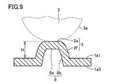
- FIG. 9 is a schematic cross-sectional view showing the structure of the fourth example of the convex portion 2.
- the portion of the convex portion 2 that contacts the ball 3 may be a flat surface.
- the convex part 2 has, for example, a planar top surface 2e and a side surface 2f that connects the top surface 2e and the guide surface 1a1.
- the side surface 2f may be a curved surface or a flat surface.
- a concave portion 8 may be formed on the first outer surface 1a3 on the opposite side of the convex portion 2.
- the recess 8 has a planar bottom surface 8a and a side surface 8b that connects the bottom surface 8a and the first outer surface 1a3.
- the top surface 2e and the bottom surface 8a may be parallel.
- the height H of the convex part 2 is 0.05 mm or more and 0.25 mm or less, for example.
- the height H is calculated as a distance from the guide surface 1a1 to the top surface 2e of the convex portion 2 in a direction along a straight line connecting the convex portion 2 and the center O1 of the ball 3, for example.
- the convex part 2 may be a different body from the guide surface 1a1.
- the convex part 2 demonstrated the case where it forms by giving press work with respect to the guide surface 1a1, the formation direction of the convex part 2 is not limited to press work.
- the convex part 2 may be formed by fixing the convex part 2 on the guide surface 1a1.
- the material constituting the convex portion 2 may be the same as or different from the material constituting the guide surface 1a1.
- the material constituting the convex portion 2 may be, for example, a resin or a metal.
- the rolling bearing 10 According to the rolling bearing 10 according to the embodiment, at least one of the plurality of pockets 9 is provided with the convex portions 2 on the guide surfaces 1a1 and 1b1.
- the sliding wear resistance is reduced as compared with the case where the convex portions 2 are not provided on the guide surfaces 1a1 and 1b1.
- wear of the guide surfaces 1a1 and 1b1 can be suppressed.
- the convex portion 2 is provided in all of the plurality of pockets 9. Thereby, in all the pockets 9, wear of the guide surfaces 1a1, 1b1 can be suppressed.
- the convex part 2 sees from the center O1 of the ball
- the ball 3 can make point contact with the cage 7 both when the ball 3 advances in the circumferential direction P with respect to the cage 7 and when the ball 3 is delayed. Therefore, wear of the guide surfaces 1a1, 1b1 can be further suppressed.
- the angle ⁇ formed by the straight line L1 passing through the convex portion 2 and the center O1 of the ball 3 and the circumferential tangent line L2 passing through the center O1 of the ball 3 is 10 ° or less. It is.
- the shape of the convex portion 2 may be a long and thin shape extending in the radial direction R of the cage 7 when viewed from the center O1 of the ball 3.
- the portion of the convex portion 2 that contacts the ball 3 may be a curved surface. Therefore, abrasion of the guide surfaces 1a1 and 1b1 can be effectively suppressed.
- the portion of the convex portion 2 that contacts the ball 3 may be a flat surface. Therefore, abrasion of the guide surfaces 1a1 and 1b1 can be effectively suppressed.
- 1 annular body 1a first annular body, 1a1, first guide surface (guide surface), 1a2, first contact surface, 1a3, first outer surface, 1b second annular body, 1b1, second guide surface (guide surface), 1b2, second 2 contact surface, 1b3 second outer surface, 2 convex portion, 2a1, 2a2, 2a first convex portion, 2b1, 2b2, 2b second convex portion, 2c third convex portion, 2d fourth convex portion, 2e top surface, 2f side, 3 balls, 4 outer ring, 5 inner ring, 6 shafts, 7 cage, 8 recess, 8a bottom surface, 8b side surface, 9 pocket, 10 rolling bearing, 11a first through hole, 11b second through hole, 12 rivets, A Axial direction, L1 straight line, L2 tangent, O1, O2 center, P circumferential direction, R radial direction.
Landscapes
- Engineering & Computer Science (AREA)
- General Engineering & Computer Science (AREA)
- Mechanical Engineering (AREA)
- Rolling Contact Bearings (AREA)
Abstract
転がり軸受(10)は、内輪(5)と、外輪(4)と、複数の玉(3)と、保持器(7)とを備える。外輪(4)は、内輪(5)の外周側に配置されている。外輪(4)は、内輪(5)の外周側に配置されている。複数の玉(3)は、内輪(5)と外輪(4)との間に配置されている。保持器(7)は、複数の玉(3)の各々を保持可能に構成され、かつ玉(3)に対向する案内面(1a1、1b1)を含む複数のポケット(9)が周方向に沿って形成されている。複数のポケット(9)の少なくとも一つには、案内面(1a1、1b1)に凸部(2)が設けられている。案内面の摩耗を抑制可能な転がり軸受を提供する。
Description
本発明は、転がり軸受に関し、特定的には、保持器を有する転がり軸受に関する。
たとえば、特開2008-175310号公報(特許文献1)には、スラストころ軸受が開示されている。当該スラストころ軸受の保持器は、一枚の環状板からなる。保持器には、針状ころを収容するためのポケットが円周上に形成されている。
転がり軸受用の保持器は、転動体が保持器に対して周方向に沿って進む場合または遅れる場合がある。このような場合、転動体が保持器のポケットを形成する案内面に衝突し、潤滑状態が悪いと案内面に摩耗が生じる。案内面が摩耗して発生した摩耗粉がグリースに混入すると潤滑状態が更に悪化し、グリースの潤滑寿命が低下する。
本発明は、上記課題を鑑みてなされたものであり、その目的は、案内面の摩耗を抑制可能な転がり軸受を提供することである。
本発明の一実施の形態に係る転がり軸受は、内輪と、外輪と、複数の玉と、保持器とを備える。外輪は、内輪の外周側に配置されている。複数の玉は、内輪と外輪との間に配置されている。保持器は、複数の玉の各々を保持可能に構成され、かつ玉に対向する案内面を含む複数のポケットが周方向に沿って形成されている。複数のポケットの少なくとも一つには、案内面に凸部が設けられている。
本発明の一実施の形態に係る転がり軸受によれば、複数のポケットの少なくとも一つには、案内面に凸部が設けられている。これにより、転動体としての玉と保持器とが面接触ではなく点接触となるため、案内面に凸部が設けられていない場合と比較して、滑り摩耗抵抗を低下させることができる。結果として、案内面の摩耗を抑制することができる。
上記一実施の形態に係る転がり軸受において好ましくは、凸部は、複数のポケットの全てに設けられている。これにより、全てのポケットにおいて、案内面の摩耗を抑制することができる。
上記一実施の形態に係る転がり軸受において好ましくは、凸部は、玉の中心から見て、周方向の一方側に設けられた第1凸部と、周方向の他方側に設けられた第2凸部とを有する。これにより、玉が保持器に対して周方向に進んだ場合および遅れた場合の双方において、玉は保持器と点接触することが可能となる。それゆえ、案内面の摩耗をより抑制することができる。
上記一実施の形態に係る転がり軸受において好ましくは、凸部と玉の中心とを通る直線と、玉の中心を通る周方向の接線とが成す角度は10°以下である。これにより、玉が保持器に対して周方向に進んだ場合または遅れた場合において、玉は保持器と点接触しやすくなる。それゆえ、案内面の摩耗をより抑制することができる。
上記一実施の形態に係る転がり軸受において、玉の中心から見て、凸部の形状は、保持器の径方向に伸びる長細い形状であってもよい。これにより、玉が保持器の径方向に対して移動した場合であっても、玉は保持器と点接触することが可能となる。それゆえ、案内面の摩耗をより抑制することができる。
上記一実施の形態に係る転がり軸受において、凸部は、保持器の径方向に離間するように配置された第3凸部および第4凸部を有していてもよい。これにより、玉が保持器の径方向に対して移動した場合であっても、玉は保持器と点接触することが可能となる。それゆえ、案内面の摩耗をより抑制することができる。
上記一実施の形態に係る転がり軸受において、玉に接触する凸部の部分は曲面であってもよい。これにより、案内面の摩耗を効果的に抑制することができる。
上記一実施の形態に係る転がり軸受において、玉に接触する凸部の部分は平面であってもよい。これにより、案内面の摩耗を効果的に抑制することができる。
本発明によれば、案内面の摩耗を抑制可能な転がり軸受を提供することができる。
以下、本発明の実施の形態について図に基づいて説明する。なお、以下の図面において同一または相当する部分には同一の参照番号を付しその説明は繰返さない。
図1を参照して、本発明の実施の形態に係る転がり軸受10の構成について説明する。
実施の形態に係る転がり軸受10は、内輪5と、外輪4と、複数の玉3と、保持器7とを主に有する。外輪4は、内輪5の外周側に配置されている。複数の玉3は、内輪5と外輪4との間に配置されている。保持器7は、内輪5の外周側であって、かつ外輪4の内周側に配置されている。外輪4および内輪5の各々は、円環状の形状を有している。内輪5の内側には、軸6が嵌合可能である。内輪5は、軸6とともに回転可能である。軸6は、内輪5の中心O2に位置する。
実施の形態に係る転がり軸受10は、内輪5と、外輪4と、複数の玉3と、保持器7とを主に有する。外輪4は、内輪5の外周側に配置されている。複数の玉3は、内輪5と外輪4との間に配置されている。保持器7は、内輪5の外周側であって、かつ外輪4の内周側に配置されている。外輪4および内輪5の各々は、円環状の形状を有している。内輪5の内側には、軸6が嵌合可能である。内輪5は、軸6とともに回転可能である。軸6は、内輪5の中心O2に位置する。
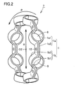
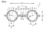
図2および図3を参照して、保持器7は、環状体1と、リベット12とを主に有している。環状体1は、第1環状体1aと第2環状体1bとを含む。第1環状体1aは、第1案内面1a1と、第1接触面1a2と、第1外側面1a3とを含む。同様に、第2環状体1bは、第2案内面1b1と、第2接触面1b2と、第2外側面1b3とを含む。第1環状体1aは、第2環状体1bと対向するように配置されている。具体的には、第1接触面1a2は、第2接触面1b2と接触している。第1案内面1a1は、第2案内面1b1から離間した状態で、第2案内面1b1に対向している。第1環状体1aには、第1外側面1a3と第1接触面1a2とを貫通する第1貫通孔11aが形成されている。同様に、第2環状体1bには、第2外側面1b3と第2接触面1b2とを貫通する第2貫通孔11bが形成されている。第1貫通孔11aおよび第2貫通孔11bにリベット12が挿入されている。第1環状体1aおよび第2環状体1bは、リベット12を用いて固定されている。第1環状体1aは軸線方向Aの一方側に配置されており、かつ第2環状体1bは軸線方向Aの他方側に配置されている。
保持器7は、複数の玉3の各々を保持可能に構成されている。図3に示されるように、複数の玉3の各々は、複数のポケット9の各々に配置されている。つまり、一つのポケット9には、一つの玉3が配置されている。ポケット9は、第1案内面1a1および第2案内面1b1を含む。言い換えれば、ポケット9は、第1案内面1a1および第2案内面1b1により構成されている。第1案内面1a1および第2案内面1b1は、玉3に対向する。玉3は、第1案内面1a1および第2案内面1b1により囲まれている。第1案内面1a1および第2案内面1b1の各々と、玉3との間には、たとえば潤滑用グリースが設けられている。図2に示されるように、保持器7には、第1案内面1a1および第2案内面1b1を含む複数のポケット9が周方向Pに沿って形成されている。ポケット9は、保持器7の周方向Pに沿って、たとえば45°間隔で8個設けられていてよい。なお、ポケット9の数は8個以外の数であってもよい。
図3に示されるように、案内面1a1、1b1には、凸部2が設けられている。具体的には、凸部2は、玉3の中心O1から見て、保持器7の周方向Pの一方側に設けられた第1凸部2aと、周方向Pの他方側に設けられた第2凸部2bとを有していてもよい。第1案内面1a1には、第1凸部2aが設けられている。第1凸部2aは、第1案内面1a1から玉3の中心O1に向かって突出するように形成されている。同様に、第2案内面1b1には、第2凸部2bが設けられている。第2凸部2bは、第2案内面1b1から玉3の中心O1に向かって突出するように形成されている。
第1案内面1a1および第2案内面1b1は、凹状の曲面である。第1案内面1a1および第2案内面1b1は、放物面であってもよい。第1凸部2aと第2凸部2bとを繋ぐ直線状に、玉3の中心O1が位置していてもよい。第1凸部2aは、軸6(図1参照)の軸線方向Aの一方側に設けられており、かつ第2凸部2bは軸線方向Aの他方側に設けられていてもよい。
図3を参照して、好ましくは、第1凸部2aと玉3の中心O1とを通る直線L1と、玉3の中心O1を通る周方向Pの接線L2とが成す角度θは10°以下である。複数のポケット9の少なくとも1つのポケット9において角度θが10°以下であり、いくつかのポケット9において角度θが10°よりも大きくてもよい。好ましくは、複数のポケット9の全てのポケット9において角度θが10°以下である。
あるポケット9の第1案内面1a1において、周方向Pの一方側に第1凸部2aが設けられており、当該ポケット9の隣のポケット9の第1案内面1a1において、周方向Pの他方側に第2凸部2bが設けられていてもよい。同様に、あるポケット9の第2案内面1b1において、周方向Pの他方側に第2凸部2bが設けられており、当該ポケット9の隣のポケット9の第2案内面1b1において、周方向Pの一方側に第1凸部2aが設けられていてもよい。
図4に示されるように、全てのポケット9の第1案内面1a1において、玉3の中心O1から見て、保持器7の周方向Pの一方側に設けられた第1凸部2a1と、周方向Pの他方側に設けられた第2凸部2b1とが設けられていてもよい。同様に、全てのポケット9の第2案内面1b1において、玉3の中心O1から見て、保持器7の周方向Pの一方側に設けられた第1凸部2a2と、周方向Pの他方側に設けられた第2凸部2b2とが設けられていてもよい。第1凸部2a2および第2凸部2b2は、周方向Pに対して線対称の位置に配置されていてもよい。
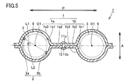
図5に示されるように、あるポケット9には、凸部2が形成されているが、他のポケット9には、凸部2が形成されていなくてもよい。あるポケット9の第1案内面1a1には、玉3の中心O1から見て、保持器7の周方向Pの一方側に設けられた第1凸部2a2が設けられており、第2案内面1b1には、周方向Pの他方側に設けられた第2凸部2b2が設けられていてもよい。当該ポケット9の隣のポケット9には凸部2が設けられていなくてもよい。つまり、複数のポケット9の少なくとも一つには、案内面1a1、1b1に凸部2が設けられている。言い換えれば、複数のポケット9のいくらかのポケット9には、凸部2が設けられていなくてもよい。好ましくは、凸部2は、複数のポケット9の全てに設けられている。
図2に示されるように、ポケット9は、保持器7の周方向Pに沿って、たとえば45°間隔で8個設けられている場合、凸部2を有するポケット9が90°毎に配置されていてもよい。たとえばあるポケット9が他のポケット9よりも負荷がかかることが決まっている場合において、より負荷がかかるポケット9のみに凸部2が設けられていてもよい。周方向Pに沿って凸部2が設けられたポケット9と、凸部2が設けられていないポケット9とが交互に配置されていてもよい。
次に、凸部の構造の具体例について説明する。
図6は、凸部2の第1の例の構造を示す斜視模式図である。図6に示されるように、玉3の中心O1から見て、凸部2の形状は、保持器7の径方向Rに伸びる長細い形状であってもよい。言い換えれば、軸線方向Aから見て、凸部2の形状は、保持器7の径方向Rに伸びる長細い形状であってもよい。凸部2は、案内面1b1の曲面形状に沿って湾曲していてもよい。凸部2は、周方向Pに対して線対称であってもよい。
図6は、凸部2の第1の例の構造を示す斜視模式図である。図6に示されるように、玉3の中心O1から見て、凸部2の形状は、保持器7の径方向Rに伸びる長細い形状であってもよい。言い換えれば、軸線方向Aから見て、凸部2の形状は、保持器7の径方向Rに伸びる長細い形状であってもよい。凸部2は、案内面1b1の曲面形状に沿って湾曲していてもよい。凸部2は、周方向Pに対して線対称であってもよい。
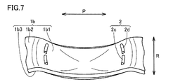
図7は、凸部2の第2の例の構造を示す斜視模式図である。図7に示されるように、凸部2は、保持器7の径方向Rに離間するように配置された第3凸部2cおよび第4凸部2dを有していてもよい。第3凸部2cは、径方向Rの一方側に設けられており、かつ第4凸部2dは、径方向Rの他方側に設けられている。第3凸部2cおよび第4凸部2dは、案内面1b1の曲面形状に沿って湾曲していてもよい。第3凸部2cおよび第4凸部2dは、周方向Pに対して線対称であってもよい。
図8は、凸部2の第3の例の構造を示す断面模式図である。図8に示されるように、凸部2は、案内面1a1と一体で形成されていてもよい。たとえば、案内面1a1に対してプレス加工を施すことにより、案内面1a1に凸部2が形成されてもよい。凸部2と反対側の第1外側面1a3には、凹部8が形成されていてもよい。図8に示されるように、玉3に接触する凸部2の部分は曲面であってもよい。凸部2の高さHは、たとえば0.05mm以上0.25mm以下である。高さHは、たとえば凸部2と玉3の中心O1とを繋ぐ直線に沿った方向における、案内面1a1から凸部2の頂点までの距離として計算される。
図9は、凸部2の第4の例の構造を示す断面模式図である。図9に示されるように、玉3に接触する凸部2の部分は平面であってもよい。凸部2は、たとえば、平面状の頂面2eと、頂面2eと案内面1a1とを繋ぐ側面2fとを有する。側面2fは、曲面であってもよいし、平面であってもよい。凸部2の反対側の第1外側面1a3には、凹部8が形成されていてもよい。凹部8は、平面状の底面8aと、底面8aと第1外側面1a3とを繋ぐ側面8bとを有する。頂面2eと底面8aとは平行であってもよい。凸部2の高さHは、たとえば0.05mm以上0.25mm以下である。高さHは、たとえば凸部2と玉3の中心O1とを繋ぐ直線に沿った方向における、案内面1a1から凸部2の頂面2eまでの距離として計算される。
なお、上記においては、凸部2が案内面と一体である場合について説明したが、凸部2は、案内面1a1と別体であってもよい。また凸部2は、案内面1a1に対してプレス加工を施すことにより形成する場合について説明したが、凸部2の形成方向はプレス加工に限定されない。たとえば案内面1a1上に凸部2を固着することにより、凸部2が形成されてもよい。凸部2を構成する材料は、案内面1a1を構成する材料と同じであってもよいし、異なっていてもよい。凸部2を構成する材料は、たとえば樹脂であってもよいし、金属であってもよい。
次に、本発明の実施の形態に係る転がり軸受の作用効果について説明する。
実施の形態に係る転がり軸受10によれば、複数のポケット9の少なくとも一つには、案内面1a1、1b1に凸部2が設けられている。これにより、転動体としての玉3と保持器7とが面接触ではなく点接触となるため、案内面1a1、1b1に凸部2が設けられていない場合と比較して、滑り摩耗抵抗を低下させることができる。結果として、案内面1a1、1b1の摩耗を抑制することができる。
実施の形態に係る転がり軸受10によれば、複数のポケット9の少なくとも一つには、案内面1a1、1b1に凸部2が設けられている。これにより、転動体としての玉3と保持器7とが面接触ではなく点接触となるため、案内面1a1、1b1に凸部2が設けられていない場合と比較して、滑り摩耗抵抗を低下させることができる。結果として、案内面1a1、1b1の摩耗を抑制することができる。
また実施の形態に係る転がり軸受10によれば、凸部2は、複数のポケット9の全てに設けられている。これにより、全てのポケット9において、案内面1a1、1b1の摩耗を抑制することができる。
さらに実施の形態に係る転がり軸受10によれば、凸部2は、玉3の中心O1から見て、周方向Pの一方側に設けられた第1凸部2aと、周方向Pの他方側に設けられた第2凸部2bとを有する。これにより、玉3が保持器7に対して周方向Pに進んだ場合および遅れた場合の双方において、玉3は保持器7と点接触することが可能となる。それゆえ、案内面1a1、1b1の摩耗をより抑制することができる。
さらに実施の形態に係る転がり軸受10によれば、凸部2と玉3の中心O1とを通る直線L1と、玉3の中心O1を通る周方向の接線L2とが成す角度θは10°以下である。これにより、玉3が保持器7に対して周方向Pに進んだ場合または遅れた場合において、玉3は保持器7と点接触しやすくなる。それゆえ、案内面1a1、1b1の摩耗をより抑制することができる。
さらに実施の形態に係る転がり軸受10によれば、玉3の中心O1から見て、凸部2の形状は、保持器7の径方向Rに伸びる長細い形状であってもよい。これにより、玉3が保持器7の径方向Rに対して移動した場合であっても、玉3は保持器7と点接触することが可能となる。それゆえ、案内面1a1、1b1の摩耗をより抑制することができる。
さらに実施の形態に係る転がり軸受10によれば、凸部2は、保持器7の径方向Rに離間するように配置された第3凸部2cおよび第4凸部2dを有していてもよい。これにより、玉3が保持器7の径方向に対して移動した場合であっても、玉3は保持器7と点接触することが可能となる。それゆえ、案内面1a1、1b1の摩耗をより抑制することができる。
さらに実施の形態に係る転がり軸受10によれば、玉3に接触する凸部2の部分は曲面であってもよい。これにより、案内面1a1、1b1の摩耗を効果的に抑制することができる。
さらに実施の形態に係る転がり軸受10によれば、玉3に接触する凸部2の部分は平面であってもよい。これにより、案内面1a1、1b1の摩耗を効果的に抑制することができる。
今回開示された実施の形態はすべての点で例示であって制限的なものではないと考えられるべきである。本発明の範囲は上記した説明ではなくて請求の範囲によって示され、請求の範囲と均等の意味および範囲内でのすべての変更が含まれることを意図される。
1 環状体、1a 第1環状体、1a1 第1案内面(案内面)、1a2 第1接触面、1a3 第1外側面、1b 第2環状体、1b1 第2案内面(案内面)、1b2 第2接触面、1b3 第2外側面、2 凸部、2a1,2a2,2a 第1凸部、2b1,2b2,2b 第2凸部、2c 第3凸部、2d 第4凸部、2e 頂面、2f 側面、3 玉、4 外輪、5 内輪、6 軸、7 保持器、8 凹部、8a 底面、8b 側面、9 ポケット、10 転がり軸受、11a 第1貫通孔、11b 第2貫通孔、12 リベット、A 軸線方向、L1 直線、L2 接線、O1,O2 中心、P 周方向、R 径方向。
Claims (8)
- 内輪と、
前記内輪の外周側に配置された外輪と、
前記内輪と前記外輪との間に配置された複数の玉と、
前記複数の玉の各々を保持可能に構成され、かつ前記玉に対向する案内面を含む複数のポケットが周方向に沿って形成された保持器とを備え、
前記複数のポケットの少なくとも一つには、前記案内面に凸部が設けられている、転がり軸受。 - 前記凸部は、前記複数のポケットの全てに設けられている、請求項1に記載の転がり軸受。
- 前記凸部は、前記玉の中心から見て、前記周方向の一方側に設けられた第1凸部と、前記周方向の他方側に設けられた第2凸部とを有する、請求項1または請求項2に記載の転がり軸受。
- 前記凸部と前記玉の中心とを通る直線と、前記玉の中心を通る前記周方向の接線とが成す角度は10°以下である、請求項1~請求項3のいずれか1項に記載の転がり軸受。
- 前記玉の中心から見て、前記凸部の形状は、前記保持器の径方向に伸びる長細い形状である、請求項1~請求項4のいずれか1項に記載の転がり軸受。
- 前記凸部は、前記保持器の径方向に離間するように配置された第3凸部および第4凸部を有する、請求項1~請求項4のいずれか1項に記載の転がり軸受。
- 前記玉に接触する前記凸部の部分は曲面である、請求項1~請求項6のいずれか1項に記載の転がり軸受。
- 前記玉に接触する前記凸部の部分は平面である、請求項1~請求項6のいずれか1項に記載の転がり軸受。
Applications Claiming Priority (2)
| Application Number | Priority Date | Filing Date | Title |
|---|---|---|---|
| JP2015053009A JP2016173125A (ja) | 2015-03-17 | 2015-03-17 | 転がり軸受 |
| JP2015-053009 | 2015-03-17 |
Publications (1)
| Publication Number | Publication Date |
|---|---|
| WO2016147880A1 true WO2016147880A1 (ja) | 2016-09-22 |
Family
ID=56920419
Family Applications (1)
| Application Number | Title | Priority Date | Filing Date |
|---|---|---|---|
| PCT/JP2016/056590 Ceased WO2016147880A1 (ja) | 2015-03-17 | 2016-03-03 | 転がり軸受 |
Country Status (2)
| Country | Link |
|---|---|
| JP (1) | JP2016173125A (ja) |
| WO (1) | WO2016147880A1 (ja) |
Families Citing this family (1)
| Publication number | Priority date | Publication date | Assignee | Title |
|---|---|---|---|---|
| DE102017111390A1 (de) | 2017-05-24 | 2018-11-29 | Schaeffler Technologies AG & Co. KG | Wälzlagerkäfig |
Citations (2)
| Publication number | Priority date | Publication date | Assignee | Title |
|---|---|---|---|---|
| JP2010038362A (ja) * | 2008-07-09 | 2010-02-18 | Ntn Corp | 減速装置 |
| US20140307988A1 (en) * | 2013-04-15 | 2014-10-16 | Precision Motion Industries, Inc. | Linear guide assembly |
-
2015
- 2015-03-17 JP JP2015053009A patent/JP2016173125A/ja active Pending
-
2016
- 2016-03-03 WO PCT/JP2016/056590 patent/WO2016147880A1/ja not_active Ceased
Patent Citations (2)
| Publication number | Priority date | Publication date | Assignee | Title |
|---|---|---|---|---|
| JP2010038362A (ja) * | 2008-07-09 | 2010-02-18 | Ntn Corp | 減速装置 |
| US20140307988A1 (en) * | 2013-04-15 | 2014-10-16 | Precision Motion Industries, Inc. | Linear guide assembly |
Also Published As
| Publication number | Publication date |
|---|---|
| JP2016173125A (ja) | 2016-09-29 |
Similar Documents
| Publication | Publication Date | Title |
|---|---|---|
| WO2010066293A1 (en) | Cage for rolling bearing, in particular for rolling bearing used in a wind turbine generator. | |
| CN106838009B (zh) | 滚动轴承 | |
| CN107420420B (zh) | 滚动轴承 | |
| JP2013015200A (ja) | 円すいころ軸受 | |
| US10527096B2 (en) | Rolling bearing | |
| US10514063B2 (en) | Rolling bearing | |
| JP2013068249A (ja) | 玉軸受及び玉軸受用の保持器 | |
| US9587676B2 (en) | Self-aligning roller bearing | |
| US9033586B2 (en) | Two piece cage for a needle bearing | |
| JP6141606B2 (ja) | 自動調心ころ軸受 | |
| JP2015102144A (ja) | 自動調心ころ軸受 | |
| WO2016147880A1 (ja) | 転がり軸受 | |
| JP2019173918A (ja) | 四点接触玉軸受およびそれに用いる玉軸受用保持器 | |
| CN104791380A (zh) | 调心滚子轴承 | |
| CN107013569B (zh) | 滚动轴承 | |
| JP2012149703A (ja) | 自動調心ころ軸受 | |
| CN107975532B (zh) | 滚动轴承 | |
| JPH10318264A (ja) | ころ軸受用合成樹脂製保持器 | |
| WO2016147881A1 (ja) | 保持器および転がり軸受 | |
| JP2012172784A (ja) | 玉軸受 | |
| JP5612946B2 (ja) | 玉軸受用波形保持器 | |
| JP4311977B2 (ja) | スラスト玉軸受 | |
| JP2010025191A (ja) | 自動調心ころ軸受 | |
| JP2014043900A (ja) | 転がり軸受 | |
| JP2011231863A (ja) | 複列軸受用保持器および複列転がり軸受 |
Legal Events
| Date | Code | Title | Description |
|---|---|---|---|
| 121 | Ep: the epo has been informed by wipo that ep was designated in this application |
Ref document number: 16764710 Country of ref document: EP Kind code of ref document: A1 |
|
| NENP | Non-entry into the national phase |
Ref country code: DE |
|
| 122 | Ep: pct application non-entry in european phase |
Ref document number: 16764710 Country of ref document: EP Kind code of ref document: A1 |