WO2016147876A1 - Dispositif et procédé d'insertion de borne pour fabrication de module de câblage - Google Patents
Dispositif et procédé d'insertion de borne pour fabrication de module de câblage Download PDFInfo
- Publication number
- WO2016147876A1 WO2016147876A1 PCT/JP2016/056535 JP2016056535W WO2016147876A1 WO 2016147876 A1 WO2016147876 A1 WO 2016147876A1 JP 2016056535 W JP2016056535 W JP 2016056535W WO 2016147876 A1 WO2016147876 A1 WO 2016147876A1
- Authority
- WO
- WIPO (PCT)
- Prior art keywords
- terminal
- connector
- electric wire
- positioning
- holder
- Prior art date
Links
Images


Classifications
-
- H—ELECTRICITY
- H01—ELECTRIC ELEMENTS
- H01R—ELECTRICALLY-CONDUCTIVE CONNECTIONS; STRUCTURAL ASSOCIATIONS OF A PLURALITY OF MUTUALLY-INSULATED ELECTRICAL CONNECTING ELEMENTS; COUPLING DEVICES; CURRENT COLLECTORS
- H01R43/00—Apparatus or processes specially adapted for manufacturing, assembling, maintaining, or repairing of line connectors or current collectors or for joining electric conductors
- H01R43/20—Apparatus or processes specially adapted for manufacturing, assembling, maintaining, or repairing of line connectors or current collectors or for joining electric conductors for assembling or disassembling contact members with insulating base, case or sleeve
-
- H—ELECTRICITY
- H01—ELECTRIC ELEMENTS
- H01B—CABLES; CONDUCTORS; INSULATORS; SELECTION OF MATERIALS FOR THEIR CONDUCTIVE, INSULATING OR DIELECTRIC PROPERTIES
- H01B13/00—Apparatus or processes specially adapted for manufacturing conductors or cables
- H01B13/012—Apparatus or processes specially adapted for manufacturing conductors or cables for manufacturing wire harnesses
- H01B13/01209—Details
-
- B—PERFORMING OPERATIONS; TRANSPORTING
- B60—VEHICLES IN GENERAL
- B60R—VEHICLES, VEHICLE FITTINGS, OR VEHICLE PARTS, NOT OTHERWISE PROVIDED FOR
- B60R16/00—Electric or fluid circuits specially adapted for vehicles and not otherwise provided for; Arrangement of elements of electric or fluid circuits specially adapted for vehicles and not otherwise provided for
- B60R16/02—Electric or fluid circuits specially adapted for vehicles and not otherwise provided for; Arrangement of elements of electric or fluid circuits specially adapted for vehicles and not otherwise provided for electric constitutive elements
- B60R16/0207—Wire harnesses
-
- Y—GENERAL TAGGING OF NEW TECHNOLOGICAL DEVELOPMENTS; GENERAL TAGGING OF CROSS-SECTIONAL TECHNOLOGIES SPANNING OVER SEVERAL SECTIONS OF THE IPC; TECHNICAL SUBJECTS COVERED BY FORMER USPC CROSS-REFERENCE ART COLLECTIONS [XRACs] AND DIGESTS
- Y10—TECHNICAL SUBJECTS COVERED BY FORMER USPC
- Y10T—TECHNICAL SUBJECTS COVERED BY FORMER US CLASSIFICATION
- Y10T29/00—Metal working
- Y10T29/49—Method of mechanical manufacture
- Y10T29/49002—Electrical device making
- Y10T29/49117—Conductor or circuit manufacturing
- Y10T29/49169—Assembling electrical component directly to terminal or elongated conductor
-
- Y—GENERAL TAGGING OF NEW TECHNOLOGICAL DEVELOPMENTS; GENERAL TAGGING OF CROSS-SECTIONAL TECHNOLOGIES SPANNING OVER SEVERAL SECTIONS OF THE IPC; TECHNICAL SUBJECTS COVERED BY FORMER USPC CROSS-REFERENCE ART COLLECTIONS [XRACs] AND DIGESTS
- Y10—TECHNICAL SUBJECTS COVERED BY FORMER USPC
- Y10T—TECHNICAL SUBJECTS COVERED BY FORMER US CLASSIFICATION
- Y10T29/00—Metal working
- Y10T29/53—Means to assemble or disassemble
- Y10T29/5313—Means to assemble electrical device
- Y10T29/532—Conductor
- Y10T29/53209—Terminal or connector
- Y10T29/53213—Assembled to wire-type conductor
Definitions
- This invention relates to a technique for inserting a terminal at an end of an electric wire into a connector.
- Patent Document 1 discloses a device for inserting a terminal into a connector housing held by a fixture.
- Patent Documents 2 to 5 Other techniques for inserting terminals into the connector housing are disclosed in Patent Documents 2 to 5.
- an object of the present invention is to make it possible to inexpensively manufacture a holder for holding a connector for inserting a terminal.
- a first aspect is a terminal insertion device for inserting a terminal into a cavity formed in a connector, which opens to one side and connects the connector along the insertion direction of the terminal with respect to the cavity.
- a holder having a holding recess that is movably held, a pushing mechanism that pushes the connector held in the holding recess so as to protrude from the opening, and a connector at a position in front of the opening.
- a terminal insertion mechanism for inserting a terminal into the cavity of the connector positioned by the positioning unit.
- a second aspect is a terminal insertion device according to the first aspect, wherein a pushing hole is formed in a portion of the holder opposite to the opening, and the pushing mechanism is formed by the pushing hole. It includes a pushing portion that is inserted into the holding recess through the portion and pushes the connector.
- a 3rd aspect is a terminal insertion apparatus which concerns on the 1st or 2nd aspect, Comprising: The holder conveyance mechanism which conveys along a connector conveyance path in the state which arranged the said some holder further, The said connector conveyance path In the above, the pushing mechanism and the positioning portion are provided at a position where the terminal insertion mechanism inserts a terminal into the cavity of the connector held by the holder.
- a fourth aspect is a terminal insertion device according to any one of the first to third aspects, wherein the positioning part includes a first positioning part that abuts a portion of a connector on a side where a terminal is inserted. And a second positioning portion that contacts both side portions of the connector, and the edge portion on the holder side of the second positioning portion is formed in a guide portion that gradually spreads outward toward the holder side. .
- a 5th aspect is a manufacturing method of a wiring module which inserts the terminal of the edge part of an electric wire with a terminal into the cavity of a connector, and makes the connector held by (a) holder project from the holder A step of moving and pressing against the positioning portion; and (b) inserting a terminal into the cavity of the connector positioned by the positioning portion.
- the terminal can be inserted into the cavity of the connector in a state where the connector is received and positioned by the positioning portion at the front position of the opening of the holder. For this reason, the terminal can be stably inserted in a state where the connector is accurately positioned. At this time, since the portion of the connector protruding from the opening of the holder is positioned by the positioning portion, it is not necessary to manufacture the holder so accurately. For this reason, the holder holding the connector can be manufactured at low cost.
- the pushing portion can be inserted into the holding recess through the pushing hole and the connector can be pushed.
- the positioning unit and the pushing mechanism may be provided at positions corresponding to the terminal insertion mechanism. For this reason, the terminal insertion device can be manufactured at a relatively low cost.
- the connector can be smoothly positioned in contact with the first positioning portion and the second positioning portion. Further, the guide portion can guide the connector so as to contact the second positioning portion.
- the terminal can be inserted into the cavity of the connector in a state where the connector protrudes from the holder and is pressed against the positioning portion to be positioned. For this reason, the terminal can be stably inserted in a state where the connector is accurately positioned. At this time, since the portion of the connector that protrudes from the holder is positioned by the positioning portion, it is not necessary to manufacture the holder so accurately. For this reason, the holder which holds a connector for inserting a terminal can be manufactured at low cost.
- FIG. 19 is a schematic sectional view taken along line XX-XX in FIG. It is the elements on larger scale of FIG. It is explanatory drawing which shows positioning operation
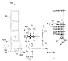
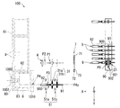
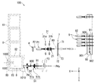
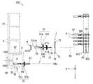
- the terminal insertion device 100 inserts the terminal 92 at the end of the terminal-attached electric wire 9 into the cavity 81 of the connector 8 and includes at least one electric wire with terminal 9 and at least one connector 8 (see FIG. 15). ).
- the terminal insertion device 100 in the present embodiment is a device that manufactures a wiring module 200 including a plurality of electric wires with terminals 9 and a plurality of connectors 8.
- the said wiring module 200 is bundled by the form along the wiring path
- the wiring module 200 is combined with at least one of other wiring modules and electric wires and bundled along a wiring path in a vehicle or the like, and configured as a wiring harness for electric wiring in the vehicle. .
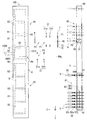
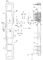
- each component does not necessarily match with respect to details such as shape and size between FIGS. 1 and 2.
- the display of some mechanisms shown in FIG. 1 is omitted.
- the terminal insertion device 100 includes an electric wire arrangement member transfer mechanism 1, terminal insertion mechanisms 2 to 5, a connector arrangement member transfer mechanism 6, an optical sensor 7, and a control unit 10. Further, the terminal insertion mechanisms 2 to 5 include a first clamping unit-related mechanism 2, a second clamping unit-related mechanism 3, a third clamping unit 4, and a fourth clamping unit-related mechanism 5. It is not essential that the terminal insertion device 100 has all of these configurations.
- the terminal insertion device may be configured to include only the holder 82, the pushing mechanism 1000, the positioning unit 1010, and the fourth clamping unit related mechanism among the terminal insertion mechanisms 2 to 5.
- the overall configuration of the terminal insertion device 100 will be described, and then the description will be focused on the configuration for positioning the connector 8 when the terminal 92 is inserted into the connector 8.
- Each of the terminal-attached electric wires 9 has an electric wire 91 and a terminal 92 connected to the end of the electric wire 91.
- the electric wire 91 is an insulated wire having a linear conductor and an insulating coating covering the periphery of the conductor.
- the terminal 92 is a conductive member such as metal.
- the terminal 92 in this embodiment is a crimp terminal, a conductor crimping portion 92a crimped to a conductor exposed at the end of the electric wire 91, a coated crimping portion 92b crimped to an insulating coating portion of the electric wire 91, and a counterpart It has the connection part 92c provided for a connection with a side terminal (refer FIG. 2).
- connection portion 92c has a cylindrical (for example, rectangular) male terminal shape, or a flat or pin-shaped male terminal shape.
- Each of the connectors 8 is a member in which a plurality of cavities 81 for accommodating the terminals 92 of each of the terminal-attached electric wires 9 are formed.
- the main body that forms the outer shape of the connector 8 is a non-conductive member, for example, a synthetic material such as polypropylene (PP), polyethylene (PE), polyvinyl chloride (PVC), polyethylene terephthalate (PET), or polyamide (PA). It is a resin member.
- the connector 8 may include a bus bar (not shown) in contact with the terminal 92 of the terminal-attached electric wire 9 inserted into the cavity 81 in the main body.
- the connector 8 is formed with a cavity 81 into which the terminals 92 can be inserted in a predetermined arrangement form.
- a lance or the like is provided in the cavity 81 as a locking structure capable of retaining and locking the terminal 92.
- the terminal 92 is inserted into the cavity 81, the lance or the like is retained and locked to the terminal 92. As a result, the terminal 92 is held in the cavity 81.
- the axial direction of the terminal 92 is inclined with respect to the axial direction of the cavity 81. For this reason, there is a risk that the terminal 92 is caught in the cavity 81, and the insertion operation of the terminal 92 is not stable. For this reason, it is preferable to hold the connector 8 in a constant posture as much as possible.
- the electric wire arrangement member transfer mechanism 1 is a mechanism that moves the electric wire arrangement member 90 while detachably holding it.
- the electric wire arraying member 90 has a long base 901 and a plurality of electric wire fastening portions 902 formed upright from the base 901.
- Each of the wire fastening portions 902 includes a pair of members that sandwich and fasten a portion of the wire 91 of the terminal-attached wire 9 near the terminal 92 by elastic force.
- the plurality of wire fastening portions 902 are formed in a row at the base portion 901. Moreover, in the electric wire arrangement
- the arrangement direction of the wire fastening portions 902 is a direction orthogonal to the direction in which the tip of the terminal 92 of each of the terminal-attached electric wires 9 faces.
- the pair of members of the wire clamp portion 902 are members that can be elastically deformed, and clamp the electric wire 91 by elastic force generated by elastic deformation.
- the pair of members of the wire fastening portion 902 may be applied with an elastic force in a direction approaching each other by an elastic body such as a spring (not shown).
- each of the terminal-attached electric wires 9 fastened to the electric wire arraying member 90 has terminals 92 connected to both ends thereof.
- sequence member 90 is supporting the part of the electric wire 91 in each of the both ends of the some electric wire 9 with a terminal by the electric wire fastening part 902. Therefore, the electric wire arrangement
- sequence member 90 has pinched the electric wire 91 by the electric wire fastening part 902 in the location twice as many as the number of the electric wires 9 with a terminal.
- the electric wire array member transfer mechanism 1 includes a fixed seat 11 and a linear actuator 12.
- the fixed seat 11 is a part that detachably holds the electric wire arranging member 90.
- the fixed seat 11 is provided with an electric wire arrangement member locking mechanism 111 having a structure for holding the electric wire arrangement member 90 and releasing the holding.
- the electric wire arrangement member locking mechanism 111 for example, a known locking mechanism capable of holding the mating member by an engaging structure and releasing the holding can be adopted.
- the direction in which the tips of the terminals 92 of each of the terminal-attached electric wires 9 supported by the electric wire arranging member 90 in a state where the electric wire arranging member 90 is held by the fixed seat 11 is referred to as a first direction.
- the first direction is the horizontal direction.
- the one direction along the arrangement direction of the wire fastening portions 902 in the situation where the wire arrangement member 90 is held by the fixed seat 11 is referred to as a second direction.
- the second direction is orthogonal to the first direction.
- the second direction is also the horizontal direction.
- the X-axis positive direction is the first direction
- the Y-axis positive direction is the second direction.
- the fixed seat 11 has the terminal 92 of each of the terminal-attached electric wires 9 supported by the electric wire arraying member 90 facing the first direction, and the electric wire retaining portion 902 is arranged in the second direction orthogonal to the first direction. Hold along.
- the linear actuator 12 moves the fixed seat 11 along the second direction, that is, along the Y-axis direction.
- the linear actuator 12 selectively positions each of the wire fastening portions 902 of the wire arranging member 90 at a predetermined starting position P0 by moving the fixed seat 11 along the second direction.
- the linear actuator 12 is, for example, a known ball screw type electric actuator.
- the position of each of the wire fastening portions 902, that is, the position of each of the wires 91 fastened to the wire fastening portion 902 is known.
- the plurality of wire fastening portions 902 are arranged in a line at regular intervals from the reference position of the fixed seat 11. In this case, if a number indicating the number of the target wire retaining portion 902 from the end is designated, a linear for moving the target wire retaining portion 902 and the electric wire 91 secured thereto to the starting position P0.
- the operation amount of the actuator 12 (the transfer direction and transfer distance of the fixed seat 11) is determined.
- the electric wire arrangement member transfer mechanism 1 includes a first retracted position A1 where the entire electric wire arrangement member 90 deviates from the starting position P0 and a first operating position where a part of the electric wire arrangement member 90 is located at the starting position P0.
- sequence member 90 can be moved along a 2nd direction in the range over A2.
- the electric wire arrangement member 90 that supports the ends of the plurality of electric wires 9 with terminals, that is, the module of the electric wire arrangement member 90 is prepared for each wiring module 200, for example.
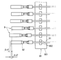
- FIG. 14 is a plan view of the end portion of the terminal-attached electric wire 9 fastened to the electric wire arraying member 90. As shown in FIG. 14, in the module of the electric wire arranging member 90, variations in positions where the electric wire fastening portions 902 sandwich the electric wires 91 of the terminal-attached electric wires 9 may occur. ⁇ x1 and ⁇ x2 in FIG. 14 represent the variation in the length of the portion of the end portion of the terminal-attached electric wire 9 that protrudes from the wire fastening portion 902.
- the cause of the variation in the position where each of the wire holding portions 902 sandwiches the electric wire 91 of the terminal-attached electric wire 9 is, for example, the variation in the process of fastening the end of the electric wire 9 with terminal to the wire holding portion 902 or during the conveyance of the electric wire arraying member 90 And the like due to an external force applied to the terminal-attached electric wire 9.
- the variation in the position where each of the electric wire fastening portions 902 sandwiches the electric wire 91 is the variation in the position of the end portion of the terminal-attached electric wire 9 arranged at the starting position P0 by the electric wire arranging member transfer mechanism 1.
- variation in the position of the electric wire 91 in the depth direction of the electric wire fastening part 902 is also considered.
- the terminal 92 may be slightly inclined with respect to the longitudinal direction of the electric wire 91 due to variations in the connection accuracy of the terminal 92 with respect to the end of the electric wire 91.
- the variation in the inclination can also be a variation in the position of the terminal 92.
- the terminal insertion device 100 has a function of correcting such a variation in the position of the end portion of the terminal-attached electric wire 9 before the terminal 92 of the terminal-attached electric wire 9 reaches the cavity 81 of the connector 8. ing.
- an end region 900 a region extending from the terminal 92 in the terminal-attached electric wire 9 to a portion near the terminal 92 of the electric wire 91 is referred to as an end region 900.
- the connector arrangement member transfer mechanism 6 is a mechanism that moves the connector arrangement member 80 while detachably holding it.
- the connector arraying member 80 has a plurality of holders 82 corresponding to the plurality of connectors 8 to be held.
- the holder 82 is supported in a state of being aligned in a row.
- the holder 82 is a member formed of resin or the like, and is formed in a square tube shape having a bottom.
- the holder 82 is formed with a holding recess 83 that opens to one side of the holder 82.
- the holding recess 83 is formed in a shape corresponding to the outer shape of the connector 8.
- the connector 8 is housed and held in the holding recess 83 with the entrance of the cavity 81 facing the opening side of the holding recess 83. In this state, the connector 8 is held movably along the insertion direction of the terminal 92 with respect to the cavity 81 (also the extending direction of the cavity 81).
- the entire connector 8 may be accommodated in the holding recess 83, or the portion of the connector 8 on the inlet side of the cavity 81 may protrude outward from the opening of the holding recess 83.
- the connectors 8 are accommodated and held in the plurality of holders 82, respectively, so that the plurality of connectors are arranged in a line and the inlets of the cavities 81 are supported in the same direction. More specifically, the connector arraying member 80 is in a state in which the inlets of the cavities 81 of the plurality of connectors 8 face the same direction, and the arraying direction of the connectors 8 is orthogonal to the direction of the inlets of the cavities 81. The plurality of connectors 8 are supported.
- the terminal insertion device 100 includes a pushing mechanism 1000 and a positioning portion 1010 described later as a configuration for accurately positioning the connector 8 without depending on the accuracy of the holder 82.
- the connector arrangement member transfer mechanism 6 includes a fixed seat 61 and a linear actuator 62.
- the fixed seat 61 is a portion that holds the connector arraying member 80 in a detachable manner.
- the fixed seat 61 is provided with a connector arrangement member locking mechanism 611 having a structure for holding the connector arrangement member 80 and releasing the holding.
- a lock mechanism similar to the wire array member lock mechanism 111 is employed as the connector array member lock mechanism 611.
- the fixed seat 61 detachably holds the connector arranging member 80 in a state in which the plurality of connectors 8 supported by the connector arranging member 80 are arranged in parallel to the arrangement direction of the wire fastening portions 902.
- the fixed seat 61 is in a state where the plurality of connectors 8 are arranged along the second direction, and the inlets of the cavities 81 of the plurality of connectors 8 face in the opposite direction of the first direction (X-axis negative direction).
- the connector arrangement member 80 is held.
- the linear actuator 62 moves the fixed seat 61 along the second direction, that is, along the Y-axis direction.
- the linear actuator 62 selectively positions the cavities 81 of the connectors 8 supported by the connector arraying member 80 at the predetermined terminal insertion position P4 by moving the fixed seat 61 along the second direction.
- the linear actuator 62 is, for example, a known ball screw type electric actuator.
- the plurality of holders 82 are conveyed along the connector conveyance path along the second direction. That is, the fixed seat 61 and the linear actuator 62 of the connector arrangement member transfer mechanism 6 are an example of a holder transport mechanism that transports along the connector transport path in a state where a plurality of holders 82 are arranged.
- the terminal insertion position P4 is a position in the second direction.
- the terminal insertion position P4 is a position aligned with a third relay position P3 described later in the second direction. That is, the coordinate P4y in the second direction representing the terminal insertion position P4 matches the coordinate in the second direction of the third relay position P3.
- each cavity 81 of each connector 8 is known.
- the positions of the cavities 81 on the connector arraying member 80 are determined by the positions at which the connectors 8 are held on the fixed seat 61 and the specifications of the shapes of the connectors 8.
- the identification code of each cavity 81 in each connector 8 and the position data on the fixed seat 61 corresponding to each identification code are set in advance.
- the position data in the second direction of the cavity 81 corresponding to the identification code is referred to move the target cavity 81 to the terminal insertion position P4.
- the operation amount of the linear actuator 62 (the transfer direction and transfer distance of the fixed seat 61) is determined.
- the target cavity 81 is an insertion destination of the terminal 92, and is sequentially selected from the plurality of cavities 81 of the plurality of connectors 8 supported by the connector arraying member 80.
- the target cavity 81 is one of the plurality of cavities 81 aligned along the third direction.
- the connector arraying member transfer mechanism 6 includes a second retracted position A3 where the entire connector arraying member 80 is disengaged from the terminal insertion position P4 and a second part where the connector arraying member 80 is partially located at the terminal insertion position P4.
- the connector arraying member 80 can be moved along the second direction within a range extending to the operating position A4.
- the direction of the first retracted position A1 viewed from the first operating position A2 is the same as the direction of the second retracted position A3 viewed from the second operating position A4.
- the second retracted position A3 is located in the first direction (X-axis positive direction) when viewed from the first retracted position A1.
- a connector array member 80 that supports a plurality of connectors 8, that is, a module of the connector array member 80 is prepared for each set of wiring modules 200, for example.
- the plurality of connectors 8 are attached to a connector array member 80 prepared in advance according to the specifications of the shape of each connector 8. Then, the module of the connector arraying member 80 is transported from the place of other processes to the place of the terminal insertion device 100 and mounted on the connector arraying member transfer mechanism 6.
- the optical sensor 7 is a transmissive optical sensor and includes a light emitting unit 71 and a light receiving unit 72.
- the light emitting unit 71 outputs detection light 73 along a plane orthogonal to the straight path R0 passing through the starting position P0 when viewed from the third direction orthogonal to the first direction and the second direction.
- the detection light 73 is light that spreads in a sheet shape along a plane.
- the positive direction of the Z axis is the third direction.
- the third direction is a vertically upward direction.
- the light receiving unit 72 of the optical sensor 7 receives the detection light 73.
- the optical sensor 7 is a sensor that detects an object that blocks the detection light 73 by detecting whether or not the light receiving level of the light receiving unit 72 is lower than a preset level.
- the optical sensor 7 detects the tip portion of the terminal 92 of the terminal-attached electric wire 9 that blocks the detection light 73.
- the terminal insertion mechanisms 2 to 5 are mechanisms for inserting the terminal 92 of the terminal-attached electric wire 9 into the target cavity 81 located at the terminal insertion position P4.
- the terminal insertion mechanisms 2 to 5 remove the end region 900 of the terminal-attached electric wire 9 from the electric wire fastening portion 902 at the starting position P0 by sandwiching and moving a part of the end region 900 of the terminal-attached electric wire 9. Then, the terminal 92 in the end region 900 of the detached wire 9 with terminal is inserted into the target cavity 81 located at the terminal insertion position P4.
- the terminal insertion mechanisms 2 to 5 include a first clamping portion 21 as a moving wire end holding portion to be described later, and a third direction transfer mechanism 22 as the wire end moving mechanism.
- the end portion is used as a mechanism for moving through the first clamping portion 21 and inserting the end portion into the cavity 81 of the connector 8.
- the first clamping portion-related mechanism 2 of the terminal insertion mechanisms 2 to 5 moves the end region 900 from the starting position P0 in advance by sandwiching and moving a part of the end region 900 of the terminal-attached electric wire 9. This is a mechanism for moving to the first relay position P1.
- the first clamping unit-related mechanism 2 includes a first clamping unit 21, a third direction transfer mechanism 22, and a first direction transfer mechanism 23.
- the first sandwiching portion 21 is a mechanism that sandwiches a part of the end region 900 of the terminal-attached electric wire 9 in a state where the tip of the terminal 92 faces the first direction from both sides along the second direction at the starting position P0. is there.
- the first clamping unit 21 includes a pair of first opposing members 211 and a first separation / contact actuator 212 that brings the pair of first opposing members 211 close to and away from each other along the second direction (Y-axis direction). is doing.
- Each of the pair of first opposing members 211 has a bifurcated portion that is bifurcated from the root portion.
- the branch part of a pair of 1st opposing member 211 is two places of the both sides of the part which the electric wire fixing part 902 in the electric wire 91 of the electric wire 9 with a terminal pinches (namely, electric wire fixing part 902 among the edge parts of the electric wire 9 with a terminal). And support with the part (except the part held by) sandwiched.
- the 1st clamping part 21 can pinch and support the part between the part hold
- the one in the positive direction of the X-axis supports the portion in between.
- the first separation actuator 212 causes the pair of first opposing members 211 to approach or separate from each other along the second direction. As a result, the first separating / connecting actuator 212 switches the state of the pair of first opposing members 211 to either a state of holding the electric wire 91 or a state of releasing the holding of the electric wire 91.
- the first separation / connection actuator 212 is, for example, a solenoid actuator or a ball screw type electric actuator.
- the 3rd direction transfer mechanism 22 of the 1st clamping part related mechanism 2 is a mechanism which moves the 1st clamping part 21 along a 3rd direction.
- the first direction transfer mechanism 23 of the first clamping unit-related mechanism 2 is a mechanism that moves the first clamping unit 21 along the first direction.
- the third direction transfer mechanism 22 and the first direction transfer mechanism 23 move the first clamping unit 21 along a plane that passes through the starting position P0 and extends along the first direction and the third direction. Accordingly, the first relay position P1 exists in a plane that passes through the starting position P0 and extends along the first direction and the third direction.
- the third direction transfer mechanism 22 moves along the third direction while directly supporting the first clamping unit 21, and the first direction transfer mechanism 23 supports the third direction transfer mechanism 22 while supporting the first direction 21. Move along one direction.
- the first direction transfer mechanism 23 includes a slide support 231 that supports the third direction transfer mechanism 22 so as to be movable along the first direction, and a linear that moves the third direction transfer mechanism 22 along the first direction. And an actuator 232.
- the third direction transfer mechanism 22 and the linear actuator 232 are, for example, a known ball screw type electric actuator.
- the third direction transfer mechanism 22 and the first direction transfer mechanism 23 move the end region 900 of the terminal-attached electric wire 9 from the starting position P0 to the first relay position P1, the first direction transfer mechanism 23 is connected to the straight path R0.
- region 900 of the electric wire 9 with a terminal is moved along. More specific operations of the third direction transfer mechanism 22 and the first direction transfer mechanism 23 will be described later.
- the 3rd direction transfer mechanism 22 and the 1st direction transfer mechanism 23 of the 1st clamping part related mechanism 2 move the edge part 900 of the electric wire 9 with a terminal by moving the 1st clamping part 21, 1st relay position P1. It is an example of the 1st clamping part transfer mechanism made to move to.
- the third direction transfer mechanism 22 raises the first clamping part 21 from a position where the end of the terminal-attached electric wire 9 held by the electric wire holding part 902 can be held (lowered position) and another position (raised). It is used as an electric wire end moving mechanism that is moved between
- the third direction transfer mechanism 22 has the first clamping part 21 in the first direction (Z-axis direction), that is, the extending direction of the terminal-attached electric wire 9 held by the electric wire fastening part 902 (X-axis direction).
- the first clamping part 21 is moved forward and backward toward the electric wire fastening part 902 along the crossing direction (the Z-axis direction which is the orthogonal direction here).
- the wire end portion moving mechanism may be any mechanism that moves the first clamping portion 21 in a direction crossing the X axis direction, and may be inclined with respect to the Z axis direction.
- the second clamping unit related mechanism 3 of the terminal insertion mechanisms 2 to 5 is a mechanism that inherits the support of the end region 900 of the terminal-attached electric wire 9 from the first clamping unit 21 at the first relay position P1. Furthermore, the second clamping unit-related mechanism 3 temporarily transfers the support of the terminal 92 of the terminal-attached electric wire 9 to and from the third clamping unit 4, and then the terminal-carrying electric wire to the fourth clamping unit-related mechanism 5. Deliver 9
- the second clamping unit related mechanism 3 includes a second clamping unit 31, a first direction transfer mechanism 32, and a second direction transfer mechanism 33.
- the second sandwiching portion 31 is configured so that a part of the terminal 92 and a portion of the wire 91 in the end region 900 of the terminal-attached electric wire 9 that the first sandwiching portion 21 sandwiches at the first relay position P1 in the second direction (Y (Axial direction) from both sides. And the 2nd clamping part 31 inherits the support of the edge part area
- the second clamping unit 31 includes a front second clamping unit 31a and a rear second clamping unit 31b. Each of the front 2nd clamping part 31a and the back 2nd clamping part 31b adjoins and separates a pair of 2nd opposing member 311 and a pair of 2nd opposing member 311 mutually along a 2nd direction (Y-axis direction). And a second separating / connecting actuator 312 to be operated.
- the pair of second opposing members 311 of the front second clamping portion 31a supports the terminal 92 in the end region 900 of the terminal-attached electric wire 9 with a part thereof being sandwiched therebetween.
- the pair of second opposing members 311 of the rear second clamping portion 31b supports a part of the electric wire 91 in the end region 900 of the terminal-attached electric wire 9 while sandwiching a part thereof.
- the operation of holding the nine electric wires 91 and the operation of releasing the holding can be performed individually.
- the second separating / connecting actuator 312 causes the pair of second opposing members 311 to approach or separate from each other along the second direction. As a result, the second separating / connecting actuator 312 changes the state of the pair of second opposing members 311 to either the state of holding the end region 900 of the terminal-attached electric wire 9 or the state of releasing the holding of the end region 900. Switch to.
- the second separating / connecting actuator 312 is, for example, a solenoid actuator or a ball screw type electric actuator.
- the first direction transfer mechanism 32 of the second clamping unit related mechanism 3 is a mechanism for moving the second clamping unit 31 along the first direction.
- the second direction transfer mechanism 33 of the second clamping unit related mechanism 3 is a mechanism for moving the second clamping unit 31 along the second direction.
- the first direction transfer mechanism 32 moves the second clamping unit 31 from the first relay position P1 to the predetermined second relay position P2.
- the second direction transfer mechanism 33 moves the second clamping unit 31 from the second relay position P2 to a predetermined third relay position P3. Further, the first direction transfer mechanism 32 and the second direction transfer mechanism 33 move the second clamping unit 31 from the third relay position P3 to the first relay position P1.
- the first direction transfer mechanism 32 moves the slide support part 321 along the first direction, and the slide support part 321 that supports the second holding part 31 movably along the first direction. And a linear actuator 322.
- the second direction transfer mechanism 33 includes a slide support portion 331 that supports the second holding portion 31 and the first direction transfer mechanism 32 movably along the second direction, and a slide support portion 331. And a linear actuator 332 that moves along the second direction.
- the third clamping part 4 of the terminal insertion mechanisms 2 to 5 is configured to provide part of the terminal 92 in the end region 900 of the terminal-attached electric wire 9 held by the second clamping part 31 at the predetermined second relay position P2. Hold it from both sides along three directions.
- the third clamping unit 4 passes the support of the terminal 92 of the terminal-attached electric wire 9 temporarily from the second clamping unit 31 to the second clamping unit 31.
- the third clamping unit 4 includes a pair of third opposing members 41 and a third separation / contact actuator 42 that brings the pair of third opposing members 41 close to and away from each other along the third direction (Z-axis direction). is doing. In the present embodiment, the third clamping unit 4 is fixed.
- the pair of third opposing members 41 supports the terminal 92 in the end region 900 of the terminal-attached electric wire 9 with a part of the terminal 92 interposed therebetween.
- the third separation actuator 42 causes the pair of third opposing members 41 to approach or separate from each other along the third direction. Thereby, the 3rd separation / connection actuator 42 switches the state of a pair of 3rd opposing member 41 to either the state which clamps the terminal 92 of the electric wire 9 with a terminal, and the state which cancels
- the third separating / connecting actuator 42 is, for example, a solenoid actuator or a ball screw type electric actuator.
- the first direction transfer mechanism 32 of the second clamping unit-related mechanism 3 changes the second and third clamping unit positional relationship that moves at least one of the second clamping unit 31 and the third clamping unit 4 along the first direction. It is an example of a mechanism.
- the first direction transfer mechanism 32 determines the positional relationship between the terminal 92 of the terminal-attached electric wire 9 held by the second clamping unit 31 and the third clamping unit 4 between the first positional relationship and the second positional relationship. Change.
- the first positional relationship is a positional relationship in which the third clamping unit 4 is separated from the terminal 92 in the first direction.
- the second positional relationship is a positional relationship in which the terminal 92 is positioned at the clamping position of the third clamping unit 4.
- the positional relationship between the terminal 92 and the third clamping unit 4 is the first positional relationship.
- the positional relationship of the terminal 92 and the 3rd clamping part 4 becomes a 2nd positional relationship.
- the fourth clamping part-related mechanism 5 of the terminal insertion mechanisms 2 to 5 is a mechanism that inherits support of the end region 900 of the terminal-attached electric wire 9 from the second clamping part 31 at a predetermined third relay position P3. Further, the fourth clamping-related mechanism 5 moves the terminal 92 of the terminal-attached electric wire 9 to the cavity 81 of the connector 8 located at the terminal insertion position P4 by holding and moving the end region 900 of the electric wire 9 with the terminal. insert.
- the fourth clamping unit-related mechanism 5 includes a fourth clamping unit 51, a third direction transfer mechanism 52, and a first direction transfer mechanism 53.
- the fourth clamping part 51 is a part of the terminal 92 and one of the electric wires 91 in the end region 900 of the terminal-attached electric wire 9 that the second clamping part 31 inherits from the third clamping part 4 at the third relay position P3. Hold each part. And the 4th clamping part 51 inherits the support of the edge part area
- the fourth clamping unit 51 includes a front fourth clamping unit 51a and a rear fourth clamping unit 51b.
- Each of the front fourth clamping part 51a and the rear fourth clamping part 51b has a pair of fourth opposing members 511 and a pair of fourth opposing members 511 that are close to and separated from each other along the second direction (Y-axis direction). And a fourth separation actuator 512 to be operated.
- the pair of fourth opposing members 511 of the front fourth clamping part 51a supports the terminal 92 in the end region 900 of the terminal-attached electric wire 9 with a part thereof being sandwiched therebetween.
- the pair of fourth opposing members 511 of the rear fourth clamping part 51b sandwich and support a part of the electric wire 91 in the end region 900 of the terminal-attached electric wire 9.
- the fourth sandwiching portion 51 has the front fourth sandwiching portion 51a and the rear fourth sandwiching portion 51b, the operation of sandwiching the terminal 92 of the terminal-attached electric wire 9, the operation of releasing the sandwiching, and the electric wire with terminal The operation of holding the nine electric wires 91 and the operation of releasing the holding can be performed individually.
- the fourth separation actuator 512 causes the pair of fourth opposing members 511 to approach or separate from each other along the second direction.
- the fourth separation actuator 512 is configured to change the state of the pair of fourth opposing members 511 between a state in which the end region 900 of the terminal-attached electric wire 9 is sandwiched and a state in which the end region 900 is released. Switch to.
- the fourth separation / connection actuator 512 is, for example, a solenoid actuator or a ball screw type electric actuator.
- front fourth clamping portion 51a and rear fourth clamping portion 51b are insertion wire end holding portions that can hold the end of the terminal-attached electric wire 9 when the terminal 92 is inserted into the cavity 81 of the connector 8. is there.
- the third direction transfer mechanism 52 of the fourth clamping unit related mechanism 5 is a mechanism for moving the fourth clamping unit 51 along the third direction.
- the third direction transfer mechanism 52 includes a front third direction transfer mechanism 52a that moves the front fourth clamping portion 51a along the third direction, and a rear third direction that moves the rear fourth clamping portion 51b along the third direction.
- Direction transfer mechanism 52b is a mechanism for moving the fourth clamping unit 51 along the third direction.
- the third direction transfer mechanism 52 of the fourth clamping unit-related mechanism 5 includes the front third direction transfer mechanism 52a and the rear third direction transfer mechanism 52b, the front fourth clamping unit 51a is moved along the third direction. And moving the rear fourth clamping part 51b along the third direction can be performed separately.
- the third direction transfer mechanism 52 is configured to calculate a distance difference in the third direction between the known third relay position P3 and the position of the target cavity 81 existing at the terminal insertion position P4.
- the fourth clamping unit 51 is moved in the third direction (Z-axis positive direction) by the amount. Of course, when the distance difference is zero, the third direction transfer mechanism 52 does not move the fourth clamping unit 51.
- the 1st direction transfer mechanism 53 is the 1st direction between the position of the entrance of the target cavity 81 which exists in the respectively known 3rd relay position P3 and terminal insertion position P4, respectively.
- the fourth clamping unit 51 is moved in the first direction (X-axis positive direction) by a distance corresponding to the sum of the difference in distance and the depth dimension of the target cavity 81.
- the first direction transfer mechanism 53 is an insertion advance / retreat drive unit that moves the front fourth clamping unit 51a and the rear fourth clamping unit 51b, which are insertion wire end holding units, forward and backward toward the cavity 81.
- the terminal 92 of the terminal-attached electric wire 9 moves from the third relay position P3 and exists in the target insertion position P4. 81 is inserted.
- the third direction transfer mechanism 52 moves the slide support part 321 along the first direction, and the slide support part 321 that supports the second holding part 31 movably along the first direction. And a linear actuator 322.
- the third direction transfer mechanism 52 moves along the third direction while directly supporting the fourth clamping unit 51, and the first direction transfer mechanism 53 supports the third direction transfer mechanism 52 while supporting the fourth direction 51. Move along one direction.
- the first direction transfer mechanism 53 includes a slide support portion 531 that supports the third direction transfer mechanism 52 movably along the first direction, and a linear that moves the third direction transfer mechanism 52 along the first direction. And an actuator 532.
- the third direction transfer mechanism 52 and the linear actuator 532 are, for example, a known ball screw type electric actuator.
- the third direction transfer mechanism 52 and the first direction transfer mechanism 53 of the fourth holding part-related mechanism 5 move the fourth holding part 51 to move the terminal 92 of the terminal-attached electric wire 9 to the cavity 81 of each connector 8. It is an example of the 4th clamping part transfer mechanism to insert.
- the second direction transfer mechanism 33 of the second holding unit related mechanism 3 is an example of a second holding unit transfer mechanism that moves the second holding unit 31 along the second direction.
- the second direction transfer mechanism 33 transfers the second holding part 31 to the second relay position P2 that inherits the support of the terminal 92 from the third holding part 4 and the third holding part that passes the support of the electric wire 9 with terminal to the fourth holding part 51. Move between the relay position P3.
- the terminal 92 is inserted into the cavity 81 of the connector 8 by the fourth clamping portion related mechanism 5 at the terminal insertion position P4.
- the terminal insertion position P4 in the connector conveyance path is a position where the terminal insertion mechanisms 2 to 5 are inserted into the cavity 81 of the connector 8 held by the holder 82. And the pushing mechanism 1000 and the positioning part 1010 are provided in this terminal insertion position P4.
- the pushing mechanism 1000 is provided on the opposite side of the terminal insertion mechanisms 2 to 5 with respect to the holder 82 at the terminal insertion position P4.
- the pushing mechanism 1000 is configured to be able to push the connector 8 held in the holding recess 83 of the holder 82 so as to protrude from the opening.
- the positioning portion 1010 is provided on the terminal insertion mechanism 2-5 side with respect to the holder 82 at the terminal insertion position P4.
- the positioning portion 1010 is configured to be able to receive and position the connector 8 at a position in front of the opening of the holding recess 83.
- the portion of the connector 8 on the inlet side of the cavity 81 is the opening of the holding recess 83. And is pressed against the positioning portion 1010. Thereby, the connector 8 is positioned with high accuracy.
- the terminals are inserted into the cavities 81 of the connector 8 positioned by the positioning portion 1010 by the terminal insertion mechanisms 2 to 5.
- the configurations of the pushing mechanism 1000 and the positioning unit 1010 will be described in detail later.
- the control unit 10 is a device that controls each actuator in the electric wire arrangement member transfer mechanism 1, the terminal insertion mechanisms 2 to 5, and the connector arrangement member transfer mechanism 6 while referring to the detection signal of the optical sensor 7. In FIG. 2, the display of the control unit 10 is omitted.
- the control unit 10 includes a calculation unit, a storage unit, and a signal interface.
- the arithmetic unit, the storage unit, and the signal interface are electrically connected.
- the calculation unit is an element or a circuit including a CPU (Central Processing Unit) that executes a process for deriving a control command for each actuator in accordance with a control program recorded in advance in the storage unit.
- a CPU Central Processing Unit
- the storage unit is a non-volatile memory that stores a control program and other data referred to by the arithmetic unit.
- the storage unit stores data such as predetermined path transfer data, terminal-cavity correspondence data, wire position data, and cavity position data.
- the predetermined path transfer data is data representing the operation procedure of the actuator of the first clamping section related mechanism 2 for moving the end region 900 of the terminal-attached electric wire 9 along the predetermined path from the starting position P0 to the linear path R0. Including. Furthermore, the predetermined route transfer data is transferred from the position when the terminal 92 is detected by the optical sensor 7 through the first relay position P1 and the second relay position P2 to the third relay position P3. It also includes data representing the operating procedure of the actuator of the second clamping unit-related mechanism 3 for movement along.
- the terminal-cavity correspondence data is data representing a correspondence relationship between each identification code of the wire retaining portion 902 sandwiching the electric wire 91 in the electric wire arraying member 90 and each identification code of the cavity 81 representing the insertion destination of the terminal 92. Further, the terminal-cavity correspondence data also represents the order of the wire fastening portions 902 that are to be positioned to the starting position P0.
- the electric wire position data includes data necessary for specifying the position of each of the electric wire fastening portions 902 in the electric wire arrangement member 90. That is, the electric wire position data includes data necessary for specifying the operation amount of the linear actuator 12 of the electric wire arrangement member transfer mechanism 1 when each of the electric wire holding portions 902 is moved to the starting position P0.
- the cavity position data specifies the position and depth dimension of each of the cavities 81 of each connector 8 supported by the connector arraying member 80 in the second direction (Y-axis direction) and the third direction (Z-axis direction). Including data necessary for.
- the positions of the inlets of the cavities 81 in the first direction (X-axis direction) are all the same known positions.
- the position data in the second direction of each of the cavities 81 in the cavity position data is obtained when the cavities 81 of the connectors 8 supported by the connector arraying member 80 are moved to the terminal insertion position P4. This data is necessary for specifying the operation amount of the linear actuator 62.
- the third position and depth data of the cavity 81 in the cavity position data are obtained when the terminal 92 of the terminal-attached electric wire 9 is moved from the third relay position P3 into the target cavity 81. This data is necessary for specifying the operation amounts of the third direction transfer mechanism 52 and the first direction transfer mechanism 53 of the related mechanism 5.
- the signal interface transmits the detection signal to the calculation unit. Further, when a control command for each actuator derived by the calculation unit is input, the signal interface converts the control command into a drive signal for each actuator and outputs the drive signal.
- the terminal insertion device 100 connects the terminals 92 of the electric wires with terminals 9 to the connectors 8. A terminal insertion step of inserting into each of the cavities 81 is executed.
- FIGS. 3 to 13 Regard the terminal insertion mechanisms 2 to 5, only the portion sandwiching a part of the end region 900 of the terminal-attached electric wire 9 is schematically displayed, and the display of other mechanisms is omitted. Has been. Further, in FIGS. 4 to 12, the display of the electric wire arrangement member transfer mechanism 1 and the connector arrangement member transfer mechanism 6 is omitted. Further, for convenience, with respect to the first clamping part 21, the second clamping part 31, the third clamping part 4 and the fourth clamping part 51, the state holding the end region 900 of the terminal-attached electric wire 9 is shown in black, The state where the end region 900 of the terminal-attached electric wire 9 is released is shown in white.
- the terminal insertion process includes a starting point / terminal insertion positioning process, a clamping start process, a first transfer primary process, a first transfer secondary process, a first transfer process, a second transfer process, a second transfer process, a third transfer process, It includes three delivery steps, a fourth transfer primary step, and a fourth transfer secondary step.
- the mechanism that operates in each process operates in accordance with the control command of the arithmetic unit that executes the control program stored in the storage unit in the control unit 10.
- the calculation unit of the control unit 10 outputs a control signal to each mechanism through the signal interface while referring to various data stored in the storage unit and the detection result of the optical sensor 7, so The process is executed.
- the module of the electric wire arranging member 90 is fixed to the fixing seat 11 in a state where the electric wire arranging member transfer mechanism 1 places the fixing seat 11 at the first retracted position A1. . Further, the module of the connector array member 80 is fixed to the fixed seat 61 in a state where the connector array member transfer mechanism 6 places the fixed seat 61 at the second retracted position A3.
- the starting point / terminal insertion positioning step includes a starting point positioning step and a terminal insertion positioning step.
- the starting point positioning step is a step in which the electric wire arranging member transfer mechanism 1 selectively positions each of the electric wire fastening portions 902 of the electric wire arranging member 90 at the starting point position P0.
- the control unit 10 sequentially specifies the target wire fastening portion 902 to be moved to the starting position P0 based on the terminal-cavity correspondence data in the storage unit.
- sequence member transfer mechanism 1 moves the electric wire arrangement
- the connector arraying member transfer mechanism 6 moves the connector arraying member 80 along the second direction, so that each cavity 81 of each connector 8 is selectively inserted in the terminal insertion position in the second direction.
- the control unit 10 sequentially specifies the target cavity 81 to be moved to the terminal insertion position P4 based on the terminal-cavity correspondence data in the storage unit.
- the connector arraying member transfer mechanism 6 moves the connector arraying member 80 along the second direction, thereby positioning the target cavity 81 specified by the control unit 10 at the terminal insertion position P4.
- the connector array member transfer mechanism 6 does not move the connector array member 80 in this step.
- the starting point positioning step and the terminal insertion positioning step are performed in parallel. Moreover, those steps may be performed sequentially.
- the starting point / terminal insertion positioning step is executed. And every time the starting point / terminal insertion positioning process is executed, the clamping start process, the first transfer primary process, the first transfer secondary process, the first transfer process, the second transfer process, the second transfer process, which will be described later, A third transfer process, a third delivery process, a fourth transfer primary process, and a fourth transfer secondary process are performed.
- step 3 is a first starting point / terminal insertion positioning step, and this step is also an operation position transition step.
- the electric wire arrangement member transfer mechanism 1 moves the electric wire arrangement member 90 that supports the end regions 900 of the plurality of terminal-attached electric wires 9 from the first retracted position A1 to the first operating position A2.
- the operation position transition process includes a second operation position transition process in which the connector array member transfer mechanism 6 moves the connector array member 80 supporting the plurality of connectors 8 from the second retracted position A3 to the second operation position A4.
- first operation position transition process and the second operation position transition process are performed in parallel. Moreover, those steps may be performed sequentially.
- the first clamping unit 21 is configured to detect the end region 900 in the terminal-attached electric wire 9 in a state where the tip of the terminal 92 faces the first direction at a predetermined starting position P0. It is a process with a part in between.
- the 1st clamping part 21 has 2 places of the electric wire 91 in the edge part area
- the first transfer primary process is performed after the third direction transfer mechanism 22 of the first holding unit related mechanism 2 moves the first holding unit 21 in the third direction by a predetermined distance.
- the first direction transfer mechanism 23 of the first clamping unit-related mechanism 2 moves in the first direction along the straight path R0.
- the first direction transfer mechanism 23 of the first clamping unit-related mechanism 2 moves the first clamping unit 21 at a first speed by a predetermined first distance along a predetermined linear path R0.
- the first distance is set in a range in which the terminal 92 does not reach the detection light 73 regardless of variations in the initial position of the electric wire 9 with terminal.
- the first direction transfer mechanism 23 moves the first clamping unit 21 at a second speed slower than the first speed along the predetermined linear path R0 until the optical sensor 7 detects the tip of the terminal 92. .
- the above operation prevents the positioning error of the terminal 92 from becoming so large that it cannot be ignored due to a delay in the feedback control for controlling the first direction transfer mechanism 23 according to the detection result of the optical sensor 7. Further, the above operation increases the transfer speed of the terminal-attached electric wire 9 while reducing the positioning error of the terminal 92 and shortens the execution time of the process.
- the first direction transfer mechanism 23 of the first holding unit related mechanism 2 moves the first holding unit 21 through the straight path from the time when the optical sensor 7 detects the terminal 92.
- the third direction transfer mechanism 22 of the first clamping unit-related mechanism 2 is opposite to the third direction (Z-axis negative) by a predetermined distance. Direction).
- the end region 900 of the terminal-attached electric wire 9 moves to the first relay position P1.
- the second holding portion 31 is a part of the terminal 92 in the end region 900 of the terminal-attached electric wire 9 held by the first holding portion 21 at the first relay position P1. And part of the electric wire 91 is sandwiched from both sides along the second direction.
- the first clamping unit 21 releases the clamping of the electric wire 91.
- the second clamping unit 31 inherits the support of the terminal-attached electric wire 9 from the first clamping unit 21.
- the second transfer step is a step in which the first direction transfer mechanism 32 of the second holding unit related mechanism 3 moves the second holding unit 31 in the first direction by a predetermined distance.
- the first direction transfer mechanism 32 is configured so that the end region 900 of the terminal-attached electric wire 9 is a second pinching position of the third pinching unit 4 from the first relay position P1 that is far from the third pinching unit 4. Move to relay position P2.
- the third clamping unit 4 is a part of the terminal 92 in the end region 900 of the terminal-attached electric wire 9 that the second clamping unit 31 holds. Is temporarily sandwiched from both sides along the third direction.
- the front second clamping part 31a temporarily releases the terminal 92 when the third clamping part 4 holds the terminal 92, and holds the terminal 92 again. That is, the third clamping unit 4 temporarily transfers the support of the terminal 92 of the terminal-attached electric wire 9 from the second clamping unit 31 and then delivers it to the second clamping unit 31.
- the rear second clamping portion 31b like the front second clamping portion 31a, temporarily releases the electric wire 91 when the third clamping portion 4 holds the terminal 92, and again It is also conceivable to hold the electric wire 91 therebetween.
- the third transfer step is a step in which the second direction transfer mechanism 33 of the second holding unit related mechanism 3 moves the second holding unit 31 in the second direction by a predetermined distance. .
- the 2nd direction transfer mechanism 33 moves the 2nd clamping part 31 from the default 2nd relay position P2 to the default 3rd relay position P3.
- the second relay position P2 is a position at which the second sandwiching portion 31 inherits the support of the terminal 92 from the third sandwiching portion 4, and the second relay position P3 is at the fourth sandwiching position of the second sandwiching portion 31. This is the position where the support of the terminal-attached electric wire 9 is handed over to the part 51.
- the fourth clamping part 51 is connected to the end of the terminal-attached electric wire 9 that the second clamping part 31 inherits from the third clamping part 4. This is a step of sandwiching a part of the terminal 92 and a part of the electric wire 91 in the region 900.
- the second clamping unit 31 releases the clamping of the end region 900 when the fourth clamping unit 51 sandwiches the end region 900 of the terminal-attached electric wire 9.
- the 4th clamping part 51 inherits the support of the electric wire 9 with a terminal from the 2nd clamping part 31.
- the third direction transfer mechanism 52 moves the fourth holding portion 51 in the third direction (the third direction (the distance difference in the third direction between the known third relay position P3 and the position of the target cavity 81). Move in the positive Z-axis direction). Of course, when the distance difference is zero, the third direction transfer mechanism 52 does not move the fourth clamping unit 51.
- the first direction transfer mechanism 53 of the fourth clamping unit related mechanism 5 is located at the entrance position of the target cavity 81 existing at the known third relay position P3 and terminal insertion position P4 (however, the connector The fourth clamping unit 51 is moved in the first direction (X-axis positive direction) by a distance corresponding to the distance difference in the first direction from the position in the state where 8 is moved to the positioning unit 1010 side. As a result, the tip of the terminal 92 is inserted into the target cavity 81.
- the fourth holding part 51 is connected to the second holding part 31 from the second holding part 31 in the third direction transfer mechanism 52 and the first direction transfer mechanism 53 of the fourth holding part related mechanism 5.
- the fourth clamping unit 51 is moved according to a moving procedure determined by comparing the third relay position P3 that has inherited the support of the attached wire 9 and the position of the cavity 81 of each of the connectors 8 set in advance.
- the first fourth transfer mechanism 53 of the fourth clamping unit-related mechanism 5 is in a state where the rear fourth clamping unit 51 b holds the electric wire 91 in the end region 900.
- the rear fourth clamping part 51b is further moved in the first direction by a distance corresponding to the depth dimension of the target cavity 81.
- the front fourth clamping part 51a releases the clamping of the terminal 92, and the front third direction transfer mechanism 52a of the fourth clamping part related mechanism 5 reaches the position where the front fourth clamping part 51a does not interfere with the connector 8. Move in the third direction.
- a positioning step is performed.
- the connector 8 is held by the holder 82 at the terminal insertion position P4. Then, the connector 8 in the holder 82 is pushed by the pushing mechanism 1000. Thereby, the connector 8 is moved to the fourth clamping unit related mechanism 5 side so that the connector 8 protrudes to the opening side of the holder 82. Then, the peripheral edge of the connector 8 on the inlet side of the cavity 81 is pressed against the positioning part 1010. Thereby, the connector 8 is accurately positioned at a fixed position regardless of the processing accuracy of the holding recess 83 of the holder 82. In this manner, the insertion of the terminal 92 is performed in the cavity 81 of the connector 8 positioned by the positioning unit 1010 by the fourth transfer primary process and the fourth transfer secondary process.
- the terminal insertion device 100 executes the steps shown above, one terminal 92 of the terminal-attached electric wire 9 is inserted into the cavity 81 of the connector 8. Then, the terminal insertion device 100 repeats the execution of each process described above until the insertion of the terminal 92 into the cavity 81 of each of the plurality of connectors 8 supported by the connector arraying member 80 is completed.
- the connector arraying member transfer mechanism 6 moves the connector arraying member 80 from the second operating position A4 to the second retracted position A3. Move. Further, the electric wire arranging member transfer mechanism 1 moves the electric wire arranging member 90 from the first operating position A2 to the first retracted position A1.
- the electric wire array member 90 and the connector array member 80 are replaced at the first retracted position A1 and the second retracted position A3.
- the connector arraying member 80 removed from the connector arraying member transfer mechanism 6 at the second retracted position A3 connects the plurality of connectors 8 constituting one set of wire harnesses or one set of subwire harnesses to the terminals 92 of the terminal-attached electric wires 9. Is supported in a lump with the inserted.
- the connector arrangement member 80 removed at the second retracted position A3 is transported to the next process place while supporting the plurality of connectors 8 into which the terminals 92 of the terminal-attached electric wires 9 are inserted.
- a plurality of terminal-attached electric wires 9 and a plurality of connectors 8 are provided, and the terminals 92 of the plurality of electric wires with terminals 9 are integrally inserted in a cavity 81 of the connector 8.
- An integrated wiring module 200 is manufactured.
- the terminal insertion device 100 includes a pushing mechanism 1000 and a positioning portion 1010 as a configuration for positioning the connector 8 with higher accuracy at the terminal insertion position P4.
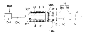
- 16 is a schematic perspective view showing the holder 82, the pushing mechanism 1000, and the positioning portion 1010 located at the terminal insertion position P4, and
- FIG. 17 is a schematic cross-sectional view thereof.
- the holder 82 is formed in a square tube shape having a bottom 82B.
- the holder 82 has a holding recess 83 that opens on the opposite side to the bottom 82B.
- the holding recess 83 is formed in the same shape as the outer periphery surrounding the plurality of cavities 81 in the connector 8. For this reason, the connector 8 can be accommodated in the holding recess 83 in a state in which the extending direction of the cavity 81 matches the depth direction of the holding recess 83.
- the depth dimension of the holding recess 83 is set to be equal to or smaller than the length dimension of the connector 8 in the extending direction of the cavity 81.
- the connector 8 opposite to the entrance of the cavity 81 can be accommodated in the holding recess 83.
- the entire connector 8 is accommodated in the holding recess 83.
- the inner peripheral shape of the holding recess 83 is configured to continue in the same shape from the opening toward the bottom 82B. For this reason, in a state where the connector 8 is housed in the holding recess 83, the connector 8 can move along the extending direction of the cavity 81 (corresponding to the insertion direction of the terminal 92 with respect to the cavity 81).
- the opening of the holding recess 83 faces the fourth clamping portion related mechanism 5 side at the coordinate P4y. For this reason, the entrance of one of the cavities 81 of the connector 8 held in the holding recess 83 also faces the fourth clamping portion related mechanism 5 side at the coordinate P4y.
- a pushing hole 82Bh is formed in a portion of the holder 82 opposite to the opening, that is, in the bottom 82B.
- the pushing hole 82Bh is preferably formed in the center of the bottom 82B, but this is not essential.
- the pushing hole portion 82Bh is formed in a size that allows the pushing portion 1002 of the pushing mechanism 1000 to be inserted.
- the push mechanism 1000 and the positioning portion 1010 are disposed at a position sandwiching the holder 82 located at the terminal insertion position P4.
- the pushing mechanism 1000 is provided on the opposite side of the fourth clamping unit related mechanism 5 with respect to the holder 82 located at the terminal insertion position P4, and the positioning unit 1010 is provided on the fourth clamping unit related mechanism 5 side. It has been.
- the pushing mechanism 1000 is composed of an air cylinder, a hydraulic cylinder, a ball screw type electric actuator, and the like.
- the pushing mechanism 1000 includes a pushing body 1001 and a pushing part 1002 that can move forward and backward from the pushing body 1001.
- the pushing portion 1002 is formed in a rod shape.
- the central axis of the pushing portion 1002 is made to coincide with the central axis of the pushing hole portion 82Bh, and the tip portion of the pushing portion 1002 is oriented toward the pushing hole portion 82Bh of the holder 82 located at the terminal insertion position P4.
- the pushing main body 1001 is supported at a fixed position.
- the push mechanism 1000 drives the push unit 1002 to advance and retreat under the control of the control unit 10.
- the advancement amount of the pushing portion 1002 is set to a size that allows the inlet portion of the cavity 81 of the connector 8 to be pressed against the positioning portion 1010.
- the tip of the pushing portion 1002 protrudes from the bottom portion 82B of the holding recess 83 through the pressing hole 82Bh and is pressed against the connector 8 in the holding recess 83.
- the connector 8 is pushed and moved so as to protrude beyond the opening of the holding recess 83, and the inlet side portion of the cavity 81 is pressed against the positioning portion 1010. Further, when the pushing portion 1002 is retracted from this state, the connector 8 can return to the holding recess 83 until it abuts against the bottom 82B in the holding recess 83.
- the following two modes can be considered as the timing for driving the push-out portion 1002 to advance and the timing for driving to retract.
- the timing for driving the pushing portion 1002 to advance is each timing before the fourth clamping portion-related mechanism 5 inserts a terminal into each cavity 81, and the pushing portion 1002 is driven to retract.
- the timing is when each of the timings after the fourth clamping unit-related mechanism 5 completes the insertion of the terminal into each cavity 81. In other words, every time the terminal 92 is inserted into each cavity 81, the pushing portion 1002 is driven forward and backward.
- the timing for driving the pushing portion 1002 to advance is the timing before the terminal 92 is first inserted into the plurality of cavities 81 of the connector 8 having the fourth clamping portion related mechanism 5,
- the timing at which the pushing portion 1002 is driven to retract is the timing after the fourth clamping unit-related mechanism 5 completes the insertion of the terminal 92 into all of the plurality of cavities 81 of the connector 8 to be inserted. Is the case. That is, this is a mode in which the pushing portion 1002 is driven forward and backward for each connector 8.
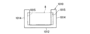
- FIG. 18 is a schematic view of the positioning portion 1010 viewed from the holder 82 side
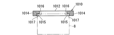
- FIG. 19 is a schematic view of the positioning portion 1010 viewed from the opposite side of the holder 82
- FIG. 20 is a schematic cross-sectional view taken along line XX-XX in FIG.
- FIG. 21 is a partially enlarged view of FIG.
- the positioning portion 1010 is configured to be able to receive and position the connector 8 at a position in front of the opening of the holding recess 83 of the holder 82.
- the positioning portion 1010 is a member formed of metal or the like, and includes a first positioning portion 1016 that abuts a portion of the connector 8 on which the terminal 92 is inserted (a surface on the inlet side of the cavity 81), and the connector 8. And a second positioning portion 1017 in contact with both side portions.
- the positioning portion 1010 is a member formed by cutting a metal plate or the like, and includes a bottom side connecting portion 1012 and a pair of side portions 1014.
- the bottom connecting portion 1012 is formed in a long shape longer than the width dimension of the connector 8.
- the side portion 1014 is formed in a long shape longer than the vertical dimension of the connector 8.
- the pair of side portions 1014 protrudes upward from both side portions of the bottom side connecting portion 1012.
- the upper surface of the bottom side connecting portion 1012 is formed as a flat surface, and the bottom portion of the connector 8 is supported on the upper surface in a mounting shape.
- a positioning recess 1015 is formed in which the side portion of the connector 8 on the side where the terminal 92 is inserted can be fitted.
- the positioning recess 1015 is formed to be recessed when viewed from the holder 82 side.
- the length of the positioning portion 1010 is set to be the same as the height of the connector 8.
- the surface of the positioning recess 1015 that faces the holder 82 is the first positioning portion 1016, and the surface of the positioning recess 1015 that faces the center in the width direction of the positioning portion 1010 is the second positioning portion 1017.
- the first positioning portions 1016 formed on the pair of side portions 1014 are provided at the same position in the moving direction of the connector 8 by the pushing portion 1002. Therefore, when the connector 8 is pushed by the pushing portion 1002, the end surface of the connector 8 on the side where the terminal 92 is inserted comes into contact with and is received by the two first positioning portions 1016 at the same time.
- the distance dimension between the second positioning portions 1017 formed on the pair of side portions 1014 is set to be the same as the distance between the side surfaces of the end portion of the connector 8 on the side where the terminal 92 is inserted. For this reason, when the connector 8 is pushed by the pushing portion 1002 and both side portions of the end portion of the connector 8 on the side where the terminal 92 is inserted are disposed between the second positioning portions 1017, the both side portions face outward. A side surface contacts the pair of second positioning portions 1017. As a result, the end of the connector 8 on the side where the terminal 92 is inserted is positioned at a fixed position in the width direction (second direction).
- the edge part by the side of the holder 82 among the 2nd positioning parts 1017 is formed in the guide part 1017g which spreads outward sequentially toward the holder 82 side.
- the guide portion 1017g is formed by rounding (R processing) the edge portion of the second positioning portion 1017 on the holder 82 side. For this reason, when the connector 8 is disposed between the pair of second positioning portions 1017, the positions of both side portions of the connector 8 and the positions of the second positioning portions 1017 are shifted in the width direction of the connector 8. As shown in FIG. 21, both side portions of the connector 8 come into contact with the guide portion 1017 g and are guided toward an accurate position between the second positioning portions 1017.
- the guide part may be formed by forming the edge part by the side of the holder 82 among the 2nd positioning parts 1017 in a slope.
- the connector array member transfer mechanism 6 causes the holder 82 and The position of the cavity 81 to be inserted is adjusted by moving the connector 8 along the second direction.
- the positioning unit 1010 is supported by the positioning unit moving mechanism 1020 so as to be movable in the second direction.
- a linear actuator such as a ball screw type electric actuator is used.
- the positioning unit 1010 is moved by the positioning unit moving mechanism 1020.
- the positioning portion 1010 can be moved to a position in front of the opening of the holder 82, so that the connector 8 protruding from the holder 82 can be received. .
- the positioning unit 1010 may be fixed at a fixed position.
- the positioning portion 1010 moves with the movement of the holder 82 and the connector 8 in the second direction. It is not necessary to incorporate a dedicated mechanism for moving in the direction. Even in this case, considering that the connector array member 80 is removed from the fixed seat 61 and is used for the recovery operation of the wiring module 200, the setting operation of the new connector 8, and the like, the entire operation of the terminal insertion device 100 is performed. As compared with the total number of holders 82 used in the above, the number of positioning portions 1010 can be reduced.
- the positioning operation by the pushing unit 1002 and the positioning unit 1010 will be described in more detail.
- the pushing portion 1002 is in a position retracted from the holder 82. Moreover, the positioning part 1010 is in the opening front position of the holding recessed part 83 of a holder.
- the pushing unit 1002 is driven to advance as shown in FIG. As a result, the pushing portion 1002 advances into the holding recess 83 through the pushing hole 82Bh and pushes and moves the connector 8 inside. Then, the connector 8 protrudes from the opening of the holding recess 83, and the portion of the connector 8 on the side where the terminal 92 is inserted is received and positioned by the positioning portion 1010. At this time, the end surface of the connector 8 on the side where the terminal 92 is inserted comes into contact with the first positioning portion 1016, so that the connector 8 is accurately positioned in the first direction. Further, since both side surfaces of the end portion of the connector 8 on the side where the terminal 92 is inserted are in contact with each other while being sandwiched between the pair of second positioning portions 1017, the connector 8 is accurately positioned also in the second direction. .
- the fourth clamping unit-related mechanism 5 inserts the terminal 92 into the cavity 81.
- the connector 8 is accurately positioned as described above by the positioning portion 1010 and is held in a state in which rattling is suppressed. For this reason, the terminal 92 can be stably inserted into the cavity 81.
- the terminal 92 When the connector 8 is separated from the positioning portion 1010 and returned into the holding recess 83, the terminal 92 is completely inserted into the cavity 81, and then the pushing portion 1002 is retracted. In this state, the fourth clamping is further performed. It is good to move so that the terminal 92 may be pushed in by the part related mechanism 5. In addition, another push mechanism for pushing the connector 8 into the holder 82 may be provided.
- the connector 8 is received and positioned by the positioning portion 1010 at a position in front of the opening of the holding recess 83 of the holder 82.
- the terminal 92 can be inserted into the eight cavities 81. For this reason, the terminal 92 can be stably inserted in a state where the connector 8 is accurately and suppressed from rattling.
- the portion of the connector 8 that protrudes from the opening of the holder 82 is positioned by the positioning portion 1010, it is not necessary to manufacture the holder 82 with such high accuracy. For this reason, the holder 82 holding the connector 8 can be manufactured at low cost.
- the pushing portion 1002 can be inserted into the holding recess 83 through the pushing hole portion 82Bh to push the connector 8.
- the connector 8 can be smoothly shifted from the state in which the connector 8 is held in the holding recess 83 to the state in which the connector 8 is positioned and held by the positioning portion 1010.
- the pushing mechanism 1000 and the positioning portion 1010 are provided at the terminal insertion position P4. For this reason, the number of arrangement of the pushing mechanism 1000 and the positioning portion 1010 can be reduced, and the terminal insertion device 100 can be manufactured at a relatively low cost.
- the positioning unit 1010 positions the end surface of the connector 8 on the side where the terminal 92 is inserted by the first positioning unit 1016, and sets both sides of the end portion of the connector 8 on the side where the terminal 92 is inserted to a pair of Positioning is performed by the second positioning unit 1017.
- the connector 8 When the connector 8 is disposed between the pair of second positioning portions 1017, the connector 8 can be guided between the pair of second positioning portions 1017 by the guide portion 1017g.
- the description has been made on the assumption that the shape of the connector 8 held by each holder 82 is the same, but when the shape of the connector 8 held by each holder 82 is different, the plurality of shapes are used. It is preferable to prepare a positioning portion corresponding to the connector 8 and to selectively move the positioning portion corresponding to the connector to be inserted into the terminal insertion position P4.
- the movement in this case can be realized, for example, by moving a member that supports a plurality of positioning portions in parallel along the second direction along the second direction.
- Terminal insertion mechanism 2 to 5 Terminal insertion mechanism 6 Connector arrangement member transfer mechanism 8 Connector 9 Electric wire with terminal 51 Fourth clamping part 51a Front fourth clamping part 51b Rear fourth clamping part 80 Connector arrangement member 81 Cavity 82 Holder 82B Bottom part 82Bh Pushing hole part 83 Holding recess 91 Electric wire 92 Terminal 100 Terminal insertion device 200 Wiring module 1000 Pushing mechanism 1001 Pushing body part 1002 Pushing part 1010 Positioning part 1016 First positioning part 1017 Second positioning part 1017g Guide part
Landscapes
- Engineering & Computer Science (AREA)
- Manufacturing & Machinery (AREA)
- Manufacturing Of Electrical Connectors (AREA)
Abstract
La présente invention a pour but de rendre possible de fabriquer à moindre coût un support destiné à retenir un connecteur afin d'insérer une borne. Pour atteindre ce but, l'invention concerne un dispositif d'insertion de borne pour insérer une borne dans une cavité formée dans un connecteur. Le dispositif d'insertion de borne est pourvu d'un support dans lequel est formée une partie de retenue en creux, d'un mécanisme de poussée pour pousser le connecteur retenu dans la partie de retenue en creux afin de faire saillie par une ouverture, d'une partie de positionnement pour recevoir et positionner le connecteur au niveau d'un emplacement situé devant l'ouverture, et d'un mécanisme d'insertion de borne pour insérer la borne dans la cavité dans le connecteur positionné par la partie de positionnement.
Priority Applications (2)
| Application Number | Priority Date | Filing Date | Title |
|---|---|---|---|
| US15/558,374 US10574017B2 (en) | 2015-03-19 | 2016-03-03 | Terminal insertion device and wiring module manufacturing method |
| CN201680014995.4A CN107408787A (zh) | 2015-03-19 | 2016-03-03 | 端子插入装置及配线模块的制造方法 |
Applications Claiming Priority (2)
| Application Number | Priority Date | Filing Date | Title |
|---|---|---|---|
| JP2015-055833 | 2015-03-19 | ||
| JP2015055833A JP2016177928A (ja) | 2015-03-19 | 2015-03-19 | 端子挿入装置及び配線モジュールの製造方法 |
Publications (1)
| Publication Number | Publication Date |
|---|---|
| WO2016147876A1 true WO2016147876A1 (fr) | 2016-09-22 |
Family
ID=56920280
Family Applications (1)
| Application Number | Title | Priority Date | Filing Date |
|---|---|---|---|
| PCT/JP2016/056535 WO2016147876A1 (fr) | 2015-03-19 | 2016-03-03 | Dispositif et procédé d'insertion de borne pour fabrication de module de câblage |
Country Status (4)
| Country | Link |
|---|---|
| US (1) | US10574017B2 (fr) |
| JP (1) | JP2016177928A (fr) |
| CN (1) | CN107408787A (fr) |
| WO (1) | WO2016147876A1 (fr) |
Cited By (1)
| Publication number | Priority date | Publication date | Assignee | Title |
|---|---|---|---|---|
| WO2018061662A1 (fr) * | 2016-09-27 | 2018-04-05 | 住友電装株式会社 | Dispositif d'insertion de borne |
Families Citing this family (3)
| Publication number | Priority date | Publication date | Assignee | Title |
|---|---|---|---|---|
| JP6951581B2 (ja) * | 2018-07-31 | 2021-10-20 | 新明和工業株式会社 | コネクタホルダ、端子挿入装置、およびワイヤハーネスの製造方法 |
| CN109605273A (zh) * | 2019-01-14 | 2019-04-12 | 鹤壁海昌专用设备有限公司 | 一种多线材插入机构 |
| US11245240B2 (en) * | 2020-01-03 | 2022-02-08 | TE Connectivity Services Gmbh | Contact retention plate for power connector assembly |
Citations (2)
| Publication number | Priority date | Publication date | Assignee | Title |
|---|---|---|---|---|
| WO2010137196A1 (fr) * | 2009-05-29 | 2010-12-02 | 住友電装株式会社 | Dispositif d'introduction de borne |
| WO2015029711A1 (fr) * | 2013-08-26 | 2015-03-05 | 住友電装株式会社 | Dispositif de production d'un faisceau de conducteurs et procédé de production associé |
Family Cites Families (16)
| Publication number | Priority date | Publication date | Assignee | Title |
|---|---|---|---|---|
| US4967470A (en) | 1990-04-20 | 1990-11-06 | Amp Incorporated | Alignment apparatus for positioning a connector housing during wire insertion |
| JP2747507B2 (ja) | 1992-07-28 | 1998-05-06 | 矢崎総業株式会社 | 端子挿入方法 |
| JP2946270B2 (ja) | 1993-10-07 | 1999-09-06 | 矢崎総業株式会社 | 払出し機構を備えたコネクタハウジングの保持方法及び装置 |
| JPH07240267A (ja) | 1994-02-28 | 1995-09-12 | Yazaki Corp | 電線付端子のコネクタハウジングへの挿入方法および挿入装置 |
| JP2003229227A (ja) * | 2002-02-01 | 2003-08-15 | Sumitomo Wiring Syst Ltd | 電気接続箱への電線のダイレクト挿入用治具 |
| JP3909053B2 (ja) * | 2003-10-06 | 2007-04-25 | 日本圧着端子製造株式会社 | 手動式コネクタ圧接機 |
| JP4351602B2 (ja) * | 2004-09-22 | 2009-10-28 | 矢崎総業株式会社 | 端子挿入装置 |
| JP4337103B2 (ja) | 2005-08-26 | 2009-09-30 | アサヒ精機株式会社 | 電線装着装置、及び挿入構造 |
| KR101063396B1 (ko) * | 2009-10-30 | 2011-09-07 | 한국단자공업 주식회사 | 차량용 콘덴서 커넥터 |
| JP5471607B2 (ja) * | 2010-03-03 | 2014-04-16 | 住友電装株式会社 | コネクタ組立用治具 |
| JP2013062151A (ja) * | 2011-09-13 | 2013-04-04 | Sumitomo Wiring Syst Ltd | ゴム栓への端子金具挿通方法及び端子金具挿通治具 |
| JP2014002846A (ja) * | 2012-06-15 | 2014-01-09 | Yazaki Corp | ジョイントコネクタ拡張構造およびジョイントコネクタ |
| JP5983563B2 (ja) | 2013-08-26 | 2016-08-31 | 住友電装株式会社 | ワイヤハーネスの製造装置及びその製造方法 |
| JP6044533B2 (ja) | 2013-12-26 | 2016-12-14 | 住友電装株式会社 | 端子挿入装置及び配線モジュールの製造方法 |
| JP2015130282A (ja) | 2014-01-08 | 2015-07-16 | 住友電装株式会社 | 端子挿入装置及び配線モジュールの製造方法 |
| JP2015130304A (ja) | 2014-01-09 | 2015-07-16 | 住友電装株式会社 | 電線処理装置及び配線モジュールの製造方法 |
-
2015
- 2015-03-19 JP JP2015055833A patent/JP2016177928A/ja active Pending
-
2016
- 2016-03-03 WO PCT/JP2016/056535 patent/WO2016147876A1/fr active Application Filing
- 2016-03-03 US US15/558,374 patent/US10574017B2/en active Active
- 2016-03-03 CN CN201680014995.4A patent/CN107408787A/zh active Pending
Patent Citations (2)
| Publication number | Priority date | Publication date | Assignee | Title |
|---|---|---|---|---|
| WO2010137196A1 (fr) * | 2009-05-29 | 2010-12-02 | 住友電装株式会社 | Dispositif d'introduction de borne |
| WO2015029711A1 (fr) * | 2013-08-26 | 2015-03-05 | 住友電装株式会社 | Dispositif de production d'un faisceau de conducteurs et procédé de production associé |
Cited By (1)
| Publication number | Priority date | Publication date | Assignee | Title |
|---|---|---|---|---|
| WO2018061662A1 (fr) * | 2016-09-27 | 2018-04-05 | 住友電装株式会社 | Dispositif d'insertion de borne |
Also Published As
| Publication number | Publication date |
|---|---|
| US10574017B2 (en) | 2020-02-25 |
| CN107408787A (zh) | 2017-11-28 |
| US20180083405A1 (en) | 2018-03-22 |
| JP2016177928A (ja) | 2016-10-06 |
Similar Documents
| Publication | Publication Date | Title |
|---|---|---|
| JP5983563B2 (ja) | ワイヤハーネスの製造装置及びその製造方法 | |
| WO2015105017A1 (fr) | Dispositif de traitement de câble électrique et procédé de production d'un module de câblage | |
| KR101753018B1 (ko) | 와이어 하네스의 제조 장치 및 그 제조 방법 | |
| WO2016147876A1 (fr) | Dispositif et procédé d'insertion de borne pour fabrication de module de câblage | |
| WO2015098524A1 (fr) | Dispositif d'insertion de borne et procédé de fabrication de module de câblage | |
| WO2017122773A1 (fr) | Dispositif d'insertion de borne, procédé d'insertion de borne, et procédé de production de module de câblage | |
| WO2015105016A1 (fr) | Dispositif d'introduction de borne et procédé de fabrication de module de câblage | |
| WO2017122653A1 (fr) | Dispositif d'insertion de borne, procédé d'insertion de borne, et procédé de fabrication de module de câblage | |
| CN112740339B (zh) | 配线构件 | |
| WO2017122708A1 (fr) | Dispositif d'introduction de bornes, procédé d'introduction de bornes et procédé de fabrication de module de câblage |
Legal Events
| Date | Code | Title | Description |
|---|---|---|---|
| 121 | Ep: the epo has been informed by wipo that ep was designated in this application |
Ref document number: 16764706 Country of ref document: EP Kind code of ref document: A1 |
|
| WWE | Wipo information: entry into national phase |
Ref document number: 15558374 Country of ref document: US |
|
| NENP | Non-entry into the national phase |
Ref country code: DE |
|
| 122 | Ep: pct application non-entry in european phase |
Ref document number: 16764706 Country of ref document: EP Kind code of ref document: A1 |