WO2016147834A1 - 工作機械 - Google Patents
工作機械 Download PDFInfo
- Publication number
- WO2016147834A1 WO2016147834A1 PCT/JP2016/055756 JP2016055756W WO2016147834A1 WO 2016147834 A1 WO2016147834 A1 WO 2016147834A1 JP 2016055756 W JP2016055756 W JP 2016055756W WO 2016147834 A1 WO2016147834 A1 WO 2016147834A1
- Authority
- WO
- WIPO (PCT)
- Prior art keywords
- unit
- apparatus main
- main body
- display
- machine tool
- Prior art date
- Legal status (The legal status is an assumption and is not a legal conclusion. Google has not performed a legal analysis and makes no representation as to the accuracy of the status listed.)
- Ceased
Links
Images



Classifications
-
- B—PERFORMING OPERATIONS; TRANSPORTING
- B23—MACHINE TOOLS; METAL-WORKING NOT OTHERWISE PROVIDED FOR
- B23Q—DETAILS, COMPONENTS, OR ACCESSORIES FOR MACHINE TOOLS, e.g. ARRANGEMENTS FOR COPYING OR CONTROLLING; MACHINE TOOLS IN GENERAL CHARACTERISED BY THE CONSTRUCTION OF PARTICULAR DETAILS OR COMPONENTS; COMBINATIONS OR ASSOCIATIONS OF METAL-WORKING MACHINES, NOT DIRECTED TO A PARTICULAR RESULT
- B23Q1/00—Members which are comprised in the general build-up of a form of machine, particularly relatively large fixed members
-
- B—PERFORMING OPERATIONS; TRANSPORTING
- B23—MACHINE TOOLS; METAL-WORKING NOT OTHERWISE PROVIDED FOR
- B23Q—DETAILS, COMPONENTS, OR ACCESSORIES FOR MACHINE TOOLS, e.g. ARRANGEMENTS FOR COPYING OR CONTROLLING; MACHINE TOOLS IN GENERAL CHARACTERISED BY THE CONSTRUCTION OF PARTICULAR DETAILS OR COMPONENTS; COMBINATIONS OR ASSOCIATIONS OF METAL-WORKING MACHINES, NOT DIRECTED TO A PARTICULAR RESULT
- B23Q17/00—Arrangements for observing, indicating or measuring on machine tools
-
- H—ELECTRICITY
- H04—ELECTRIC COMMUNICATION TECHNIQUE
- H04Q—SELECTING
- H04Q9/00—Arrangements in telecontrol or telemetry systems for selectively calling a substation from a main station, in which substation desired apparatus is selected for applying a control signal thereto or for obtaining measured values therefrom
Definitions
- the present invention relates to a machine tool including an operation panel having an imaging unit that is movable with respect to an apparatus main body and images an operation target unit such as a spindle.
- NC device numerically controlled machine tool
- an operation instruction corresponding to the operation of the apparatus body is input from an operation panel provided on the apparatus body.
- This operation panel is often separated from the actual processing room, etc., especially in maintenance work and adjustment work, etc., it was difficult to operate the operation panel while actually viewing the operation target part such as the spindle. .
- Patent Document 1 when the operation screen of the operation target unit is selected on the main operation panel, the operation screen corresponding to the operation target unit is displayed on the display unit of the portable sub operation panel, and according to the operation target unit.
- a technique for assigning the operation buttons to the sub operation panel is disclosed.
- Patent Document 2 the position of the sub operation panel is detected by a position sensor, and an image of the operation target unit and the operation key of the operation target unit are displayed on the display unit based on the detection result. Techniques to do this are disclosed.
- Patent Document 3 does not disclose a configuration in which the operation panel is operated by being removed from the apparatus main body or carried.
- An object of the present invention is to provide a machine tool capable of easily operating an operation target portion using the displayed operation means.
- a machine tool includes an apparatus main body that processes a predetermined workpiece, an operation panel that is provided so as to be movable with respect to the apparatus main body, and an imaging unit that performs imaging on the apparatus main body side.
- a display unit that displays an image captured by the imaging unit on the operation panel, and a display control unit that displays on the display unit an operation unit that operates the apparatus body.
- a predetermined mark is provided on a predetermined operation target portion of the apparatus main body that is operated by the operation of the operation panel.
- the operation panel is provided with reading means for reading the mark by photographing the operation target portion including the mark, and the display control means is provided with the mark by the reading means. Based of the information read, wherein the operation means for performing operation of the operation target unit, that the said operation object portion during shooting and configured to display on the display unit.
- the operator of the apparatus main body can freely select the operation target portion using the operation panel that is movable with respect to the apparatus main body.
- the image of the selected operation target unit and the operation means corresponding to the operation target unit are displayed on the display unit of the operation panel. Therefore, the operator of the apparatus main body uses the operation means displayed on the display unit while visually confirming the operation of the operation target part displayed on the display unit of the operation panel movable relative to the apparatus main body.
- a machine tool that can be easily operated can be provided.
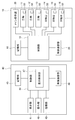
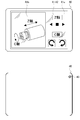
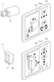
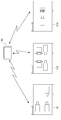
- FIG. 1 It is a perspective view showing the outline of the whole composition of the machine tool concerning one embodiment of the present invention. It is a perspective view which shows the external appearance of the front side of the automatic lathe apparatus shown in FIG. It is a perspective view which shows the external appearance of the back side of the automatic lathe apparatus shown in FIG. It is a block diagram for demonstrating the structure of the apparatus main body of a machine tool, and a sub operation panel, and the process between these. It is a top view which shows the external appearance of the front side of a sub operation panel, and the external appearance of a back side, respectively. It is a figure which shows the condition where the operator image
- the automatic lathe device 100 shown in FIGS. 1 to 3 is an embodiment of a machine tool according to the present invention.
- the automatic lathe apparatus 100 is configured such that an apparatus main body 10 for machining a predetermined workpiece is covered with an exterior cover 22.
- the apparatus body 10 includes a bed 21 as shown in FIG. Three modules M1, M2, and M3 are mounted on the bed 21. Each of the modules M1, M2, and M3 includes spindles 11, 15, 16, and the like that hold spindles 11, 12, 13, and various tools 17 that process the workpiece.
- the door 22a of the exterior cover 22 can be opened to perform operations while visually recognizing these operations.
- a main operation panel 30 is fixedly provided on the front side of the exterior cover 22 of the apparatus main body 10.
- a holder 23 is provided on the back side of the exterior cover 22.
- a sub operation panel 40 is detachably attached to the holder 23.
- the sub operation panel 40 is a terminal device that is detachable from the apparatus main body 10. By removing the sub operation panel 40 from the holder 23, the sub operation panel 40 can be freely carried independently from the apparatus main body 10. When the operator or the like freely carries the sub operation panel 40, the sub operation panel 40 is provided so as to be movable with respect to the apparatus main body 10.
- the sub operation panel 40 is configured by, for example, a tablet personal computer.
- the apparatus body 10 includes a control unit 18, a storage unit 19, and a wireless communication unit 20.
- the storage unit 19, the wireless communication unit 20, the operation targets such as the spindles 11, 12, 13, the tool post 14, 15, 16 and the main operation panel 30 are connected to the control unit 18.
- the main spindles 11, 12, 13 and the tool rests 14, 15, 16 are automatically controlled by the control unit 18.
- the operation of the main operation panel 30 and the sub operation panel 40 is controlled through the control unit 18.
- An operator of the apparatus main body 10 can perform various operations of the apparatus main body 10 by operating the main operation panel 30 and the sub operation panel 40.
- the control unit 18 can be composed of a CPU (Central Processing Unit) or the like.
- the storage unit 19 can be configured from a recording medium such as a RAM (Random Access Memory), a ROM (Read Only Memory), a nonvolatile semiconductor memory such as a flash memory, an SD card, or an external hard disk.
- Processing programs and application software are stored in advance in the ROM of the storage unit 19.
- the control unit 18 can perform operation control of the entire apparatus main body 10 including automatic operation, using the RAM of the storage unit 19 as a work memory, for example.
- the storage unit 19 stores in advance predetermined information used for operation of the apparatus main body 10 and the like.
- Marks 50 are attached to the operating parts (operation target parts) such as the spindles 11, 12, 13 and the tool rests 14, 15, 16 and the like.
- identification information for identifying the operation target part is recorded.
- a QR code (registered trademark) of a two-dimensional code is used as the mark 50.
- the QR code registered trademark
- identification information of the operation target unit for example, the type of the operation target unit, the model information and the name of the apparatus main body 10, and the like can be recorded.
- the main operation panel 30 includes operation means, a display unit, and the like.
- the operation means includes buttons for inputting operation instructions.
- An operation screen or the like is displayed on the display unit.
- An operation instruction corresponding to the operation of the apparatus main body 10 is input from the operation means to the main operation panel 30.
- the control unit 18 allows the operation target units such as the main spindles 11 to perform independent operations based on the input operation instruction.
- the input of operation instructions to the apparatus main body 10 is normally performed by the main operation panel 30.
- the sub operation panel 40 includes a display unit 41, an operation unit 42, an imaging unit (camera) 43, a control unit 44, a storage unit 45, and a wireless communication unit 46.
- the display unit 41, the operation unit 42, the imaging unit 43, the storage unit 45, and the wireless communication unit 46 are connected to the control unit 44 and controlled by the control unit 44.
- the display unit 41 is provided on the surface of the sub operation panel 40.
- the display unit 41 displays information related to operation of the apparatus main body 10 and other information.
- a touch panel display on which a so-called touch panel is mounted is used as the display unit 41.
- the display surface of the display unit 41 also functions as a touch panel type operation unit 42.
- the control unit 44 can be composed of a CPU or the like.
- the storage unit 45 can be configured from a recording medium such as a RAM, a non-volatile semiconductor memory such as a ROM or a flash memory, an SD card, or an external hard disk.
- the control unit 44 can control the operation of the entire sub-operation panel 40 using, for example, the RAM of the storage unit 45 as a work memory in accordance with application software stored in advance in the ROM of the storage unit 45.
- the storage unit 45 stores information on the operation unit 42 for operating the operation target unit on which the mark 50 is arranged, operation guidance information corresponding to the operation target unit, and the like for each mark 50. Stored in advance.
- the information of the operation unit 42 may be image information such as buttons, icons, software keyboards (hereinafter referred to as “buttons”) representing operation instructions corresponding to the operations of the operation target units of the apparatus body 10.
- the operation guide is a so-called operation guide.
- operation guidance information in this embodiment, in addition to the axis image and its name, the apparatus main body 10 and the operation target unit corresponding to the operation by the operation unit 42 including axis information such as the axis image and its name.
- axis information such as the axis image and its name.
- setting information set in advance or virtually set, information necessary for the setup work, and the like can be considered.
- information such as the Z axis representing the axes of the main axes 11, 12, and 13, the X axis perpendicular to the Z axis in the vertical direction, the Y axis perpendicular to the Z axis in the horizontal direction, and the C axis representing the rotation angle center can be given.
- information such as the name of the operation target unit and the operation method can be used as operation guide information.
- the imaging unit 43 includes a lens, an imaging element, and the like. As shown in FIG. 5, the imaging unit 43 can capture a video such as a still image or a moving image of the operation target unit via a lens provided on the back surface of the sub operation panel 40.
- the imaging unit 43 may be built in the sub operation panel 40. It may be provided separately from the sub operation panel 40 or separable, and may transmit the photographing information to the sub operation panel 40 by wire or wireless. Moreover, it is good also as a structure image
- the door 22a of the exterior cover 22 is opened.
- the operator uses the imaging unit 43 to capture an image of the operation target part such as the spindle 11 including the mark 50 arranged on the surface thereof.
- the video imaged by the imaging unit 43 is displayed on the display surface of the display unit 41.
- the mark 50 is located within a predetermined shooting range.
- the imaging unit 43 performs focusing on the mark 50 and captures an image of the mark 50.
- the video of the mark 50 is transmitted to the control unit 44 as a video signal.
- the control unit 44 converts and analyzes the video signal of the mark 50 and reads information recorded on the mark 50.
- the imaging unit 43 and the control unit 44 function as a reading unit that reads the mark 50 of the operation target unit.
- general-purpose QR code (registered trademark) reading software or the like can be used for photographing the mark 50 and analyzing the video.
- the display control unit 47 provided in the control unit 44 identifies the operation target unit.
- Information on the operation unit 42 corresponding to the identified operation target unit and operation guide information are acquired from the storage unit 45.
- the display control unit 47 generates a display image of the operation unit 42 such as a button based on the acquired information. This display image is displayed in the operation unit display area 41a on the display surface of the display unit 41 in a state where it can be operated.
- a display image of the operation guidance is generated based on the acquired information in correspondence with the shooting conditions such as the shooting angle of the operation target unit during shooting.
- the display image of the operation guidance and the video of the operation target part being photographed are combined and displayed in the operation target part display area 41 b on the display surface of the display unit 41.
- Conventionally known appropriate graphic software can be used for synthesizing the operation guide and the image of the operation target portion.
- the spindle 11 is specified as the operation target unit.
- the image of the main shaft 11 being photographed in which the operation guide images such as the Z-axis and C-axis are combined, and the operation unit 42 according to the operation of the main shaft 11 (for example, the Z-axis direction) are displayed on the display unit 41.
- a movement instruction button, a rotation instruction button in the C-axis direction, their names, and the like are displayed.
- the direction and name of each axis is information that is preset or virtually set for the apparatus main body 10 and the operation target unit as information necessary for the setup work or information corresponding to the operation by the operation unit 42.
- the operator can easily recognize the setting status for the operation target portion actually captured.
- the operator visually recognizes the actual operation of the operation target part such as the spindle 11 displayed in the operation target part display area 41b, and presses the button or the like of the operation part 42 displayed in the operation part display area 41a with a finger or a pen. Touch with.
- the operator can input an operation instruction for the operation target unit. Therefore, the operator can easily perform operations such as maintenance without comparing the operation target unit such as the spindle 11 and the operation unit 42 or checking the main operation panel 30.
- an imaging unit such as a camera is arranged in advance in the apparatus main body 10 so that the portion where the workpiece and the tool 17 abut can be enlarged and photographed.
- the corresponding part such as the spindle 11 is imaged once by the imaging unit 43 provided in the sub operation panel 40 once.
- an image captured by the camera disposed in the apparatus main body 10 is displayed in the operation target unit display area 41b. With this captured image, minute alignment between the workpiece and the cutting edge of the tool 17 can be performed.
- the operation unit 42 When the operator inputs an operation instruction from the operation unit 42, the operation unit 42 outputs an operation instruction signal corresponding to the input operation instruction to the control unit 44.
- the control unit 44 transmits an operation instruction signal to the apparatus main body 10 side by the wireless communication unit 46.
- the control unit 18 receives an operation instruction signal from the sub operation panel 40 by the wireless communication unit 20.
- the wireless communication unit 46 and the wireless communication unit 20 communicate with each other via a wireless LAN.
- the wireless communication unit 46 and the wireless communication unit 20 are configured by a wireless LAN board provided with a wireless LAN interface.
- An example of a wireless LAN communication method is WiFi (registered trademark).
- a short-range wireless communication method such as Bluetooth (registered trademark) or ZigBee (registered trademark) can also be used.
- the control unit 18 operates the operation target unit according to the operation instruction signal received by the wireless communication unit 20.
- the operator operates the main spindles 11, 12, 13, each tool post 14, 15, 16, and other operation target units via the control unit 18 by operating the sub operation panel 40. Etc.
- the sub operation panel 40 can be used in place of the main operation panel 30 when the movement of the operation target portion cannot be sufficiently confirmed while inputting the operation instruction to the main operation panel 30.
- the operation target part such as the spindle 11 is operated from the back side of the apparatus main body 10 or the processing chamber side.
- the operator can directly select the operation target unit by simply capturing an image of the operation target unit including the mark 50 with the imaging unit 43 of the sub operation panel 40 provided movably with respect to the apparatus main body 10. Only the operation unit 42 corresponding to the operation target unit is displayed on the display unit 41 of the sub operation panel 40 together with the real-time video of the operation target unit. The operator operates the operation unit 42 according to the operation guidance while visually recognizing the operation target unit displayed on the display unit 41. By this operation, the operator can operate a desired operation target unit. The operability and workability of the apparatus main body 10 are improved.
- the display control unit 47 displays the operation guide such as the Z-axis and the C-axis in a three-dimensional manner according to the change. The operator can smoothly operate the spindle 11 in an arbitrary direction and shooting conditions while visually recognizing the display unit 41.
- the operator may change the subject to be photographed from the spindle 11 to the tool rest 14.
- the imaging unit 43 detects the mark 50 disposed on the tool post 14 and shoots the video.
- the display unit 41 Based on the read information of the mark 50, the display unit 41 has an operation unit 42 corresponding to the operation of the tool post 14 and operation guidance such as Z-axis, X-axis, Y-axis, tool identification numbers T 1 and T 2.
- An image of the tool post 14 combined with is displayed. There is no need for the operator himself to switch the operation target part.
- the image of the operation unit 42 and the operation target unit of the display unit 41 is automatically switched to an image corresponding to the tool post 14 simply by photographing the operation target unit including the mark 50 by the imaging unit 43. The operator can smoothly operate the tool post 14.
- FIG. 8 shows a modification of the present embodiment.
- the modification there are a plurality of (three in the example of FIG. 8) apparatus main bodies 10, 110, and 210 having the same configuration as or different from the apparatus main body 10 of the present embodiment.
- the sub operation panel 40 can be configured to be used for operation of a desired operation target portion of the three apparatus main bodies 10, 110, and 210.
- a unique mark is placed on each operation target part of each device body 10, 110, 210.
- the reading means of the sub operation panel 40 By reading this mark with the reading means of the sub operation panel 40, it is possible to recognize which device main body 10, 110, 210 is the operation target portion.
- the display unit 41 Based on the read information, the display unit 41 displays an operation unit 42 corresponding to a desired operation target unit selected by the operator, and an image of the operation target unit being photographed with a predetermined operation guide.
- the operator can operate a desired operation target portion of each of the apparatus main bodies 10, 110, and 210 using one sub operation panel 40. The convenience of the machine tool can be improved.
- the manufacturing cost of the apparatus main bodies 10, 110, 210 can be reduced. For example, it is effective when the sub-operation panel 40 is used at the time of maintenance of the apparatus main bodies 10, 110, and 210, and the usage frequency is relatively low.
- the device main bodies 10, 110, and 210 may be connected to the same LAN. You may be connected in separate LAN. It is sufficient if communication with the sub operation panel 40 is possible.
- each of the apparatus main bodies 10, 110, and 210 may be connected to a predetermined LAN to which the apparatus main body belongs by a wireless LAN. It may be connected by wire via a network cable or the like.
- sub operation panel 40 and the apparatus main bodies 10, 110, and 210 may directly communicate with each other as in an ad hoc mode or the like. Communication may be performed via a wireless LAN host such as an access point as in the infrastructure mode.
- the sub operation panel 40 can be connected to a LAN to which the device main bodies 10, 110, 210 belong by wire.
- the sub operation panel 40 to which a wired connection is applied may be provided with an interface for connecting to the LAN with a wired connection. Examples of the interface include a wired LAN board.
- sub operation panel 40 of the present embodiment can be applied as a main operation panel.
- the tablet-type personal computer is applied to the sub operation panel 40 of the present embodiment, it is not limited to the configuration of the present embodiment.
- a portable information terminal device a general-purpose personal computer (particularly a laptop computer), or the like can be applied.
- the sub operation panel 40 is detachably attached to the apparatus main body 10, but is not limited to the configuration of the present embodiment.
- the sub operation panel 40 may be movable with respect to the holder 23 of the apparatus main body 10. For example, it can also be set as the structure attached or detached by means other than the holder 23.
- FIG. Furthermore, a part of the apparatus main body 10 provided with the sub operation panel 40 may be separated from the apparatus main body 10 and moved to a position where the operation target portion can be photographed.
- the control unit 44 includes a display unit 41, an operation unit 42, an imaging unit 43, a wireless communication unit 46, and the like according to application software processing procedures stored in advance in the ROM of the storage unit 45. Is to control. Therefore, by replacing or editing the stored application software, it is possible to apply not only the automatic lathe device 100 but also as an operation panel of various machine tools. Furthermore, it can be applied as an operation panel for inputting operation instructions to the apparatus main body of various apparatuses other than the machine tool.
- the image information of operation guidance corresponding to the operation target unit is stored in the storage unit 45 of the sub operation panel 40, but the present invention is not limited to this.
- image information of operation guidance and the like are stored in the storage unit 19 on the apparatus main body 10 side.
- image information of operation guidance is transmitted from the apparatus main body 10 side to the sub operation panel 40 side.
- the transmitted operation guidance image may be combined with the image of the operation target unit and displayed on the display unit 41 of the sub operation panel 40.
- the sub operation panel 40 identifies the operation target unit by reading the QR code (registered trademark), which is the mark 50 arranged in the operation target unit, by the reading unit.
- the mark 50 is not limited to the QR code (registered trademark). Other two-dimensional codes and one-dimensional codes such as bar codes can be used as long as the operation target parts can be individually identified.
- a configuration may also be adopted in which the captured image of the operation target portion is directly recognized as a mark.
- the mark 50 can be composed of numbers, characters, symbols, characters, and the like. Based on the mark 50 such as a number read by the reading unit, information on the operation target part stored in advance in the storage unit 45 may be acquired to identify the operation target part.
- the automatic lathe device 100 of this embodiment is an example of a machine tool.
- the machine tool according to the present invention is not limited to an automatic lathe device, and may be a machine tool other than a lathe device (particularly, numerically controlled).
Landscapes
- Engineering & Computer Science (AREA)
- Mechanical Engineering (AREA)
- Computer Networks & Wireless Communication (AREA)
- Numerical Control (AREA)
- Machine Tool Units (AREA)
- Machine Tool Sensing Apparatuses (AREA)
Abstract
装置本体に対して移動自在な操作盤の表示部に表示される操作対象部の動作等を視認しながら、表示部の操作手段を用いて操作対象部を容易に操作することが可能な工作機械を提供する。 自動旋盤装置(100)を、装置本体(10)に、メイン操作盤(30)とサブ操作盤(40)とを設けて構成する。装置本体(10)を、主軸(11,12,13)、刃物台(14,15,16)、制御部(18)、記憶部(19)、無線通信部(20)を備えて構成する。サブ操作盤(40)を、表示部(41)、操作部(42)、撮像部(43)、制御部(44)、記憶部(45)を備えて構成する。撮像部(43)で主軸(11)等の操作対象部に配されたマーク(50)を含めて操作対象部を撮影してマーク(50)を読み取り、この読み取り情報に基づいて、制御部(44)の表示制御部(47)が操作対象部の操作を行う操作部(42)と、操作案内が合成された状態の撮影中の操作対象部とを表示部(41)に表示する。
Description
本発明は、装置本体に対して移動自在で主軸等の操作対象部を撮影する撮像部を有する操作盤を備えた工作機械に関する。
数値制御式の工作機械(NC装置)などでは、装置本体の動作に対応した操作指示を装置本体に設けられた操作盤から入力するようになっている。この操作盤と実際の加工室等とは離れている場合が多く、特にメンテナンス作業や調整作業等では、主軸等の操作対象部を実際に視認しながら操作盤を操作するのは困難であった。
そこで、装置本体に設けられた操作盤に加えて、着脱式で持ち運びができる小型のサブ操作盤を用いたものが提案されている(例えば、特許文献1、2参照)。
特許文献1には、メインの操作盤で操作対象部の操作画面を選択すると、その操作対象部に応じた操作画面を可搬式のサブ操作盤の表示部に表示し、その操作対象部に応じた操作ボタンをサブ操作盤に割り当てる技術が開示されている。
特許文献2には、位置センサによってサブ操作盤の位置を検知し、検出結果に基づいて、作業者の視認風景に合わせた操作対象部の画像と、操作対象部の操作キーを表示部に表示する技術が開示されている。
また、操作対象部をカメラで撮影し、その撮影画像を表示部に表示し、この表示部上でタッチパネル操作により作業者が操作対象部を選択すると、該操作対象部に応じた制御スイッチが表示部に表示され、操作対象部の監視と制御とを行うことを可能とした監視制御装置も提案されている(特許文献3)。
上記特許文献1、2に記載の発明では、サブ操作盤を装置本体から取り外すことで、メイン操作盤から離れた加工室等でも、操作対象部を視認しながら操作対象部に応じた操作ボタン等を操作することができる。
しかしながら、サブ操作盤の表示部に表示される画像は、操作対象部を模式的に表したアイコン画像や予め撮影した画像であるため、操作対象部の実際の動作を表示部上でリアルタイムに確認することができず、操作者は表示部と操作対象部とを頻繁に見比べながら操作する必要がある。また、特許文献3には、操作盤を装置本体から取り外したり持ち運んだりして操作する構成は開示されていない。
したがって、従来技術では、装置本体に対して移動自在な操作盤を用いて、装置本体を容易に操作できるように考慮された工作機械は開示がない。
本発明は上記事情に鑑みなされたものであり、装置本体の操作者が装置本体に対して移動自在な操作盤の表示部に表示される操作対象部の動作等を視認しながら、表示部に表示された操作手段を用いて操作対象部を容易に操作することが可能な工作機械を提供することを目的とするものである。
本発明に係る工作機械は、所定のワークの加工を行う装置本体と、該装置本体に対して移動自在に設けられ該装置本体を操作する操作盤と、前記装置本体側の撮影を行う撮像部とを備え、前記操作盤に、前記撮像部によって撮影された映像が表示される表示部と、前記装置本体の操作を行う操作手段を操作可能な状態で前記表示部に表示する表示制御手段とを設け、前記操作手段による前記操作盤の操作に応じて前記装置本体が所定の作動を行う工作機械において、前記操作盤による操作で作動する前記装置本体の所定の操作対象部に、所定のマークが配され、前記操作盤に、前記操作対象部を、前記マークを含めて撮影することによって前記マークを読み取る読み取り手段を設け、前記表示制御手段を、前記読み取り手段による前記マークの読み取り情報に基づいて、前記操作対象部の操作を行う操作手段と、撮影中の前記操作対象部とを前記表示部に表示するように構成したことを特徴とする。
本発明に係る工作機械によれば、装置本体の操作者が装置本体に対して移動自在な操作盤を用いて、操作対象部を自由に選択することができる。選択した操作対象部の映像と操作対象部に応じた操作手段とが操作盤の表示部に表示される。したがって、装置本体の操作者が装置本体に対して移動自在な操作盤の表示部に表示される操作対象部の動作等を視認しながら、表示部に表示された操作手段を用いて操作対象部を容易に操作することが可能な工作機械を提供することができる。
以下、本発明に係る工作機械の実施形態について、図面を参照して説明する。図1~図3に示した自動旋盤装置100は、本発明に係る工作機械の一実施形態である。自動旋盤装置100は、所定のワークを機械加工する装置本体10が、外装カバー22に覆われて構成されている。
装置本体10は、図1に示すようにベッド21を備えている。ベッド21上に3台のモジュールM1,M2,M3を搭載している。各モジュールM1,M2,M3は、主軸11,12,13、ワークを加工する各種工具17が保持された刃物台14,15,16等を備えている。
主軸11,12,13や刃物台14,15,16のメンテナンスや調整を行う場合には、外装カバー22の扉22aを開放することで、これらの動作等を視認しながら作業を行うことができる。
図2に示すように、装置本体10の外装カバー22の正面側に、メイン操作盤30が固定されて設けられている。
図3に示すように、外装カバー22の背面側にホルダ23が設けられている。ホルダ23にサブ操作盤40が着脱自在に装着されている。サブ操作盤40は、装置本体10に対して着脱自在の端末装置である。サブ操作盤40は、ホルダ23から取り外すことで、装置本体10から独立して自在に持ち運び可能な状態となる。操作者等が、サブ操作盤40を自在に持ち運ぶことによって、サブ操作盤40は、装置本体10に対して移動自在に設けられている。サブ操作盤40は、例えば、タブレット型パーソナルコンピュータによって構成されている。
装置本体10は、図4に示すように、制御部18と、記憶部19と、無線通信部20とを備えている。記憶部19及び無線通信部20並びに主軸11,12,13、刃物台14,15,16等の操作対象部及びメイン操作盤30は、制御部18に接続されている。各主軸11、12、13や刃物台14,15,16は、制御部18によって自動制御される。その他にも、メイン操作盤30やサブ操作盤40の操作によって制御部18を介して動作制御される。装置本体10の操作者は、メイン操作盤30やサブ操作盤40の操作によって、装置本体10の各種操作等を行うことができる。
制御部18は、CPU(Central Processing Unit)等から構成することができる。記憶部19は、RAM(Random Access Memory)や、ROM(Read Only Memory)、フラッシュメモリ等の不揮発性の半導体メモリ、SDカード、又は外付けハードディスク等の記録媒体から構成することができる。
記憶部19のROMには、加工プログラムやアプリケーションソフト(プログラム)が予め記憶されている。このプログラムにしたがって、制御部18は、例えば記憶部19のRAMをワークメモリとして用いて、自動運転を含む装置本体10全体の作動制御を行うことができる。記憶部19には、プログラムの他にも、装置本体10の作動等に用いられる所定の情報が予め記憶されている。
主軸11,12,13、刃物台14,15,16等の作動部(操作対象部)には、マーク50が付されている。マーク50には、操作対象部を識別するための識別情報が記録されている。本実施形態では、マーク50として二次元コードのQRコード(登録商標)を用いている。QRコード(登録商標)には、操作対象部の識別情報として、例えば操作対象部の型式、装置本体10の機種情報や名称等を、数値化した番号を記録することができる。
メイン操作盤30は、操作手段、表示部等を備えている。操作手段は、操作指示を入力するボタン等からなる。表示部には、操作画面等が表示される。メイン操作盤30に、装置本体10の動作に対応した操作指示を操作手段から入力する。操作指示の入力によって、制御部18により、各主軸11等の操作対象部は入力された操作指示に基づいて互いに独立した動作を行うことができる。装置本体10に対する操作指示の入力は、通常はこのメイン操作盤30によって行われる。
サブ操作盤40は、図4、図5に示すように、表示部41と、操作部42と、撮像部(カメラ)43と、制御部44と、記憶部45と、無線通信部46とを備えている。表示部41、操作部42、撮像部43、記憶部45及び無線通信部46は、制御部44に接続され、該制御部44によって制御される。
表示部41は、サブ操作盤40の表面に設けられている。表示部41には、装置本体10の操作等に関する情報やその他の情報が表示される。本実施形態では、表示部41として、いわゆるタッチパネルが搭載されたタッチパネルディスプレイを用いている。表示部41の表示面は、タッチパネル式の操作部42としての機能を兼ねている。
制御部44は、CPU等から構成することができる。記憶部45は、RAMや、ROM、フラッシュメモリ等の不揮発性の半導体メモリ、SDカード、又は外付けハードディスク等の記録媒体から構成することができる。制御部44は、記憶部45のROMに予め記憶されているアプリケーションソフトにしたがって、例えば記憶部45のRAMをワークメモリとして用いて、サブ操作盤40全体の作動制御を行うことができる。
記憶部45には、上記プログラム等の他に、マーク50が配された操作対象部を操作するための操作部42の情報、操作対象部に対応する操作案内の情報等が、マーク50ごとに予め記憶されている。
操作部42の情報としては、装置本体10の各操作対象部の動作に対応した操作指示を表すボタンやアイコン、ソフトウェアキーボード等(以下、ボタン等という。)の画像情報等が考えられる。
操作案内とは、いわゆる操作ガイドである。操作案内の情報として、本実施例では、軸の画像及びその名称等の他、軸の画像及びその名称等の軸情報を含む、操作部42による操作に対応して装置本体10や操作対象部に対して予め設定、又は仮想的に設定されている設定情報や、段取り作業に必要な情報等が考えられる。例えば、主軸11,12,13の軸線を表すZ軸、Z軸と垂直方向において直交するX軸、Z軸と水平方向において直交するY軸、回転角中心を表すC軸等の情報が挙げられる。これらの他にも、例えば、操作対象部の名称や操作方法等の情報を操作案内の情報とすることができる。
撮像部43は、レンズや撮像素子等を備えている。撮像部43は、図5に示すようにサブ操作盤40の背面に設けられたレンズを介して、操作対象部の静止画、動画等の映像を撮影することができる。撮像部43は、サブ操作盤40に内蔵されたものでもよい。サブ操作盤40と別個に又は分離可能に設けられ、有線又は無線により撮影情報をサブ操作盤40に送信するものでもよい。また、背面以外に設けたレンズを介して撮影する構成としてもよい。操作者が表示部41を視認しながら操作対象部を撮影できればいずれの構成でもよい。
操作対象部のメンテナンス作業を行う場合、例えば、図6に示すように、外装カバー22の扉22aを開放する。扉22aが開放された加工室内において、操作者は撮像部43によって、主軸11等の操作対象部の映像を、その表面に配されたマーク50を含めて撮影する。撮像部43で撮影された映像は、表示部41の表示面に表示される。
この操作対象部の撮影中に、所定の撮影範囲内にマーク50が位置する。撮像部43は、マーク50への焦点合わせを行って、マーク50の映像を撮影する。このマーク50の映像は、映像信号となって制御部44に送信される。制御部44は、マーク50の映像信号を変換、解析してマーク50に記録された情報を読み取る。このように、撮像部43と制御部44とは、操作対象部のマーク50を読取る読み取り手段として機能する。マーク50の撮影や映像の解析には、汎用的なQRコード(登録商標)の読み取りソフト等を使用することができる。
マーク50の読み取り情報、すなわち操作対象部の識別情報に基づいて、制御部44に設けられた表示制御部47が操作対象部を特定する。特定した操作対象部に応じた操作部42の情報と、操作案内の情報とが記憶部45から取得される。
表示制御部47は、取得した情報に基づいてボタン等の操作部42の表示画像を生成する。この表示画像を操作可能な状態で表示部41の表示面の操作部表示領域41aに表示する。また、撮影中の操作対象部の撮影アングル等の撮影条件に対応させて、取得した情報に基づいて操作案内の表示画像を生成する。この操作案内の表示画像と撮影中の操作対象部の映像とを合成して表示部41の表示面の操作対象部表示領域41bに表示する。操作案内と操作対象部の映像との合成には、従来公知の適宜のグラフィックソフトを用いることができる。
図6の例では、操作対象部として主軸11が特定される。図7の紙面上図に示すようにZ軸、C軸等の操作案内の画像が合成された撮影中の主軸11の映像と、主軸11の操作に応じた操作部42(例えば、Z軸方向への移動指示ボタン、C軸方向への回転指示ボタンやそれらの名称等)とが、表示部41に表示される。特に各軸の方向や名称は、段取り作業に必要な情報、あるいは操作部42による操作に対応する情報として、装置本体10や操作対象部に対して予め設定、又は仮想的に設定されている情報であり、実際に撮影された状態の操作対象部に対する設定状況の認識を操作者は容易に行うことが可能となる。
操作者は、操作対象部表示領域41bに表示された主軸11等の操作対象部の実際の動作を視認しながら、操作部表示領域41aに表示された操作部42のボタン等を指やペンなどで触れる。操作者は操作対象部に対する操作指示を入力することができる。そのため、操作者は主軸11等の操作対象部と操作部42とを見比べたり、メイン操作盤30を確認したりすることなく、メンテナンス等の作業を容易に行うことができる。
また例えば、ワークと工具17とが当接する部分を拡大して撮影できるように、予め装置本体10内に個別にカメラ等の撮像部を配置する。いったんサブ操作盤40に設けられた撮像部43によって、主軸11等の対応部分の撮像を行う。操作対象部に対する操作指示を入力できる状態とした後、操作対象部表示領域41bに、装置本体10内に配置された前記カメラによる撮像映像を表示させる。この撮像映像によって、ワークと工具17の刃先との微小な位置合わせを行うこともできる。
操作者が操作部42から操作指示を入力すると、操作部42は、入力された操作指示に対応した操作指示信号を制御部44に出力する。制御部44は、無線通信部46によって操作指示信号を装置本体10側に送信する。装置本体10では、制御部18が、無線通信部20によってサブ操作盤40からの操作指示信号を受信する。
無線通信部46及び無線通信部20は、無線LANによって互いに通信を行う。無線通信部46及び無線通信部20は、無線LANインターフェースを備えた無線LANボード等によって構成される。無線LANの通信方式としては、例えばWiFi(登録商標)等が挙げられる。また、Bluetooth(登録商標)、ZigBee(登録商標)等の近距離無線の通信方式を用いることもできる。
制御部18は、無線通信部20によって受信した操作指示信号に応じて操作対象部を動作させる。このように、操作者は、サブ操作盤40を操作することによって、制御部18を介して各主軸11,12,13、各刃物台14,15,16、その他の操作対象部を動作させること等ができる。
以上説明したように、メイン操作盤30に操作指示を入力しながらでは、操作対象部の動きを十分に確認できないような場合に、メイン操作盤30に代わってサブ操作盤40を用いることができる。例えば、操作対象部のメンテナンスや調整作業を行う際などに、装置本体10の背面側や加工室側から主軸11等の操作対象部を確認しながら操作する場合等に適している。
さらに、メイン操作盤30やサブ操作盤40のメニュー画面等から操作者が手動で操作対象部を選択する必要がない。装置本体10に対して移動自在に設けられたサブ操作盤40の撮像部43でマーク50を含む操作対象部の映像を撮影するだけで、操作対象部をダイレクトに選択することができる。サブ操作盤40の表示部41には、操作対象部のリアルタイムの映像とともに操作対象部に応じた操作部42のみが表示される。操作者は、表示部41に表示された操作対象部を視認しながら、操作案内にしたがって操作部42を操作する。この操作により、操作者は所望の操作対象部を動作させることができる。装置本体10の操作性や作業性が向上する。
また、操作者が移動したりして撮像部43による主軸11等の撮影アングルや撮影倍率等の撮影条件が変化する場合がある。この場合でも、該変化に応じて表示制御部47が、Z軸、C軸等の操作案内を三次元的に変化させて表示する。操作者は表示部41を視認しながら、任意の方向や撮影条件で主軸11の操作を円滑に行うことができる。
また、図7の紙面下図に示すように、操作者が、撮影対象を主軸11から刃物台14へ変更する場合がある。この場合、撮像部43は刃物台14に配されたマーク50を検知してその映像を撮影する。このマーク50の読み取り情報に基づいて、表示部41には刃物台14の操作に応じた操作部42と、Z軸、X軸、Y軸、工具の識別番号T1、T2等の操作案内が合成された刃物台14の映像が表示される。操作者自身が操作対象部の切替え動作を行う必要がない。撮像部43でマーク50を含む操作対象部を撮影するだけで、表示部41の操作部42及び操作対象部の画像が刃物台14に対応した画像に自動的に切替わる。操作者は、刃物台14の操作を円滑に行うことができる。
本実施形態の変形例を図8に示す。変形例では、本実施形態の装置本体10と同様の構成または異なる構成の複数(図8の例では3つ)の装置本体10,110,210が存在する。この場合、サブ操作盤40を、これら3つの装置本体10,110,210の所望の操作対象部の操作に用いるように構成することができる。
各装置本体10,110,210の各操作対象部にそれぞれ固有のマークを配する。このマークをサブ操作盤40の読み取り手段で読み取ることで、何れの装置本体10,110,210の操作対象部であるかを認識することができる。この読み取り情報に基づいて、操作者が選択した所望の操作対象部に応じた操作部42と、所定の操作案内が合成された撮影中の操作対象部の映像とを表示部41に表示する。これによって、操作者は、1つのサブ操作盤40を用いて、各装置本体10,110,210の所望の操作対象部を動作させることができる。工作機械の利便性を向上させることができる。
また、3つの装置本体10,110,210のそれぞれに個別にサブ操作盤40を設ける必要がない。装置本体10,110,210の製造コストを低減することが可能となる。例えば、サブ操作盤40が装置本体10,110,210のメンテナンスの際等に使われる程度で、使用頻度が比較的低い場合等に有効である。
各装置本体10,110,210は、各装置本体10,110,210が同一のLAN内に接続されていてもよい。別々のLAN内に接続されていてもよい。サブ操作盤40との通信が可能であればよい。また、各装置本体10,110,210は、属する所定のLANに、無線LANによって接続されていてもよい。ネットワークケーブル等を介して有線で接続されていてもよい。
また、サブ操作盤40と装置本体10,110,210とは、アドホックモード等のように互いに直接通信してもよい。インフラストラクチャー・モード等のようにアクセスポイントのような無線LANのホストを介して通信してもよい。
また、サブ操作盤40は、各装置本体10,110,210が属するLANに、有線によって接続することもできる。有線によるものを適用するサブ操作盤40は、LANに有線で接続するためのインターフェースを備えたものとすればよい。インターフェースとしては、例えば有線用のLANボード等が挙げられる。
また、本実施形態のサブ操作盤40をメイン操作盤として適用することもできる。
また、本実施形態のサブ操作盤40は、タブレット型のパーソナルコンピュータを適用しているが、本実施形態の構成に限定されることはない。例えば、携帯情報端末装置や、汎用のパーソナルコンピュータ(特にラップトップ式のもの)などを適用することができる。
また、本実施形態では、サブ操作盤40を装置本体10に着脱自在に装着した構成としているが、本実施形態の構成に限定されることはない。サブ操作盤40が装置本体10のホルダ23に対して移動自在であればよい。例えば、ホルダ23以外の手段で着脱する構成とすることもできる。さらにはサブ操作盤40を設けた装置本体10の一部を、装置本体10から分離等して操作対象部を撮影可能な位置まで移動させる構成とすることもできる。
本実施形態のサブ操作盤40は、記憶部45のROMに予め記憶されているアプリケーションソフトの処理手順にしたがって、制御部44が表示部41、操作部42、撮像部43、無線通信部46等を制御するものである。そのため、記憶させておくアプリケーションソフトを入れ替えたり編集したりすることで、自動旋盤装置100に限らず、種々の工作機械の操作盤として適用することが可能となる。更には、工作機械以外の様々の装置の装置本体への操作指示の入力用の操作盤として適用することも可能となる。
また、本実施形態では、操作対象部に対応する操作案内の画像情報等は、サブ操作盤40の記憶部45に記憶しているが、本発明がこれに限定されることはない。例えば、操作案内の画像情報等を、装置本体10側の記憶部19に記憶させておく。無線通信部20及び無線通信部46を介した装置本体10とサブ操作盤40との通信により、操作案内の画像情報等を装置本体10側からサブ操作盤40側に送信する。送信された操作案内の画像を操作対象部の映像と合成してサブ操作盤40の表示部41へ表示するように構成することもできる。
本実施形態のサブ操作盤40は、操作対象部に配されたマーク50であるQRコード(登録商標)を読み取り手段で読み取ることよって、操作対象部を特定する。このマーク50がQRコード(登録商標)に限定されることはない。操作対象部を個別に識別できるものであれば、他の二次元コードや、バーコード等の一次元コードを用いることもできる。また、AR(拡張現実)技術を用いて、操作対象部にARマーカを配した構成とすることもできる。撮影した操作対象部の画像をそのままマークとして認識する構成とすることもできる。また、マーク50を、数字、文字、記号、キャラクター等で構成することもできる。読み取り手段で読み取った数字等のマーク50に基づいて、記憶部45に予め記憶していた操作対象部の情報を取得して、操作対象部を特定する構成とすることもできる。
本実施形態の自動旋盤装置100は工作機械の一例である。本発明に係る工作機械は、自動旋盤装置に限定されるものではなく、旋盤装置以外の工作機械(特に数値制御のもの)であってもよい。
以上、本発明の実施形態を図面により詳述してきたが、上記実施形態は本発明の例示にしか過ぎないものである。本発明は上記実施形態の構成にのみ限定されるものではない。本発明の要旨を逸脱しない範囲の設計の変更等があっても、本発明に含まれる。
[関連出願への相互参照]
本出願は、2015年3月13日に日本国特許庁に出願された特願2015-050533に基づいて優先権を主張し、その全ての開示は完全に本明細書で参照により組み込まれる。
本出願は、2015年3月13日に日本国特許庁に出願された特願2015-050533に基づいて優先権を主張し、その全ての開示は完全に本明細書で参照により組み込まれる。
Claims (9)
- 所定のワークの加工を行う装置本体と、該装置本体に対して移動自在に設けられ該装置本体を操作する操作盤と、前記装置本体側の撮影を行う撮像部とを備え、
前記操作盤に、前記撮像部によって撮影された映像が表示される表示部と、前記装置本体の操作を行う操作手段を操作可能な状態で前記表示部に表示する表示制御手段とを設け、
前記操作手段による前記操作盤の操作に応じて前記装置本体が所定の作動を行う工作機械において、
前記操作盤による操作で作動する前記装置本体の所定の操作対象部に、所定のマークが配され、
前記操作盤に、前記操作対象部を、前記マークを含めて撮影することによって前記マークを読み取る読み取り手段を設け、
前記表示制御手段を、前記読み取り手段による前記マークの読み取り情報に基づいて、前記操作対象部の操作を行う操作手段と、撮影中の前記操作対象部とを前記表示部に表示するように構成したことを特徴とする工作機械。 - 前記操作盤は、前記装置本体の操作者が持ち運び可能となるよう前記装置本体に対して着脱自在に設けられたことを特徴とする請求項1に記載の工作機械。
- 前記表示制御手段は、所定の操作案内が合成された状態の撮影中の前記操作対象部を前記表示部に表示することを特徴とする請求項1または2に記載の工作機械。
- 前記操作案内が、操作部による操作に対応して前記装置本体又は前記操作対象部に対して予め設定、又は仮想的に設定されている設定情報を含むことを特徴とする請求項3に記載の工作機械。
- 前記操作案内が、段取り作業に必要な情報を含むことを特徴とする請求項3または4に記載の工作機械。
- 前記表示制御手段は、前記撮像部による前記操作対象部の撮影条件が変化したとき、該撮影条件の変化に応じて、前記操作案内の表示を変化させるように構成されたことを特徴とする請求項3から5のいずれか一項に記載の工作機械。
- 前記表示制御手段は、前記読み取り手段で読み取った前記マークが変更されたとき、前記表示部への前記操作手段の表示を、変更された前記マークに応じた前記操作対象部の前記操作手段に切替えて表示するように構成されたことを特徴とする請求項1から6のいずれか一項に記載の工作機械。
- 前記操作盤が、タブレット型パーソナルコンピュータであることを特徴とする請求項1から7のいずれか一項に記載の工作機械。
- 前記表示部は、タッチパネル式操作手段として前記操作手段の機能を兼ねるものであることを特徴とする請求項1から8のいずれか一項に記載の工作機械。
Priority Applications (1)
| Application Number | Priority Date | Filing Date | Title |
|---|---|---|---|
| JP2017506172A JP6709210B2 (ja) | 2015-03-13 | 2016-02-26 | 工作機械 |
Applications Claiming Priority (2)
| Application Number | Priority Date | Filing Date | Title |
|---|---|---|---|
| JP2015050533 | 2015-03-13 | ||
| JP2015-050533 | 2015-03-13 |
Publications (1)
| Publication Number | Publication Date |
|---|---|
| WO2016147834A1 true WO2016147834A1 (ja) | 2016-09-22 |
Family
ID=56918890
Family Applications (1)
| Application Number | Title | Priority Date | Filing Date |
|---|---|---|---|
| PCT/JP2016/055756 Ceased WO2016147834A1 (ja) | 2015-03-13 | 2016-02-26 | 工作機械 |
Country Status (3)
| Country | Link |
|---|---|
| JP (1) | JP6709210B2 (ja) |
| TW (1) | TW201638692A (ja) |
| WO (1) | WO2016147834A1 (ja) |
Cited By (3)
| Publication number | Priority date | Publication date | Assignee | Title |
|---|---|---|---|---|
| WO2023033095A1 (ja) * | 2021-09-06 | 2023-03-09 | Dmg森精機株式会社 | 表示制御装置 |
| JP2023038154A (ja) * | 2021-09-06 | 2023-03-16 | Dmg森精機株式会社 | 表示制御装置 |
| JP7499664B2 (ja) | 2020-09-29 | 2024-06-14 | 株式会社ディスコ | 加工システム |
Families Citing this family (1)
| Publication number | Priority date | Publication date | Assignee | Title |
|---|---|---|---|---|
| CN110431497A (zh) * | 2017-03-30 | 2019-11-08 | 西铁城时计株式会社 | 机床的控制装置 |
Citations (4)
| Publication number | Priority date | Publication date | Assignee | Title |
|---|---|---|---|---|
| JP2009255224A (ja) * | 2008-04-16 | 2009-11-05 | Murata Mach Ltd | 加工機械の操作盤 |
| JP2012090077A (ja) * | 2010-10-20 | 2012-05-10 | Konica Minolta Business Technologies Inc | 携帯端末及び処理装置の操作方法 |
| JP2014215780A (ja) * | 2013-04-24 | 2014-11-17 | 京セラドキュメントソリューションズ株式会社 | 操作入力装置及びプログラム並びに画像形成システム |
| DE102013105226A1 (de) * | 2013-05-22 | 2014-11-27 | Elb-Schliff Werkzeugmaschinen Gmbh | Bedieneinrichtung für Werkzeugmaschine |
-
2016
- 2016-02-26 JP JP2017506172A patent/JP6709210B2/ja active Active
- 2016-02-26 WO PCT/JP2016/055756 patent/WO2016147834A1/ja not_active Ceased
- 2016-03-04 TW TW105106735A patent/TW201638692A/zh unknown
Patent Citations (4)
| Publication number | Priority date | Publication date | Assignee | Title |
|---|---|---|---|---|
| JP2009255224A (ja) * | 2008-04-16 | 2009-11-05 | Murata Mach Ltd | 加工機械の操作盤 |
| JP2012090077A (ja) * | 2010-10-20 | 2012-05-10 | Konica Minolta Business Technologies Inc | 携帯端末及び処理装置の操作方法 |
| JP2014215780A (ja) * | 2013-04-24 | 2014-11-17 | 京セラドキュメントソリューションズ株式会社 | 操作入力装置及びプログラム並びに画像形成システム |
| DE102013105226A1 (de) * | 2013-05-22 | 2014-11-27 | Elb-Schliff Werkzeugmaschinen Gmbh | Bedieneinrichtung für Werkzeugmaschine |
Cited By (4)
| Publication number | Priority date | Publication date | Assignee | Title |
|---|---|---|---|---|
| JP7499664B2 (ja) | 2020-09-29 | 2024-06-14 | 株式会社ディスコ | 加工システム |
| WO2023033095A1 (ja) * | 2021-09-06 | 2023-03-09 | Dmg森精機株式会社 | 表示制御装置 |
| JP2023038154A (ja) * | 2021-09-06 | 2023-03-16 | Dmg森精機株式会社 | 表示制御装置 |
| JP7286839B2 (ja) | 2021-09-06 | 2023-06-05 | Dmg森精機株式会社 | 表示制御装置 |
Also Published As
| Publication number | Publication date |
|---|---|
| JPWO2016147834A1 (ja) | 2017-12-21 |
| JP6709210B2 (ja) | 2020-06-10 |
| TW201638692A (zh) | 2016-11-01 |
Similar Documents
| Publication | Publication Date | Title |
|---|---|---|
| JP5404450B2 (ja) | 加工状況監視装置 | |
| EP2082850B1 (en) | Generating device of processing robot program | |
| KR100762380B1 (ko) | 로봇 위치 교시를 위한 이동 제어 장치, 로봇의 위치 교시장치, 로봇 위치 교시를 위한 이동 제어 방법, 로봇의 위치교시 방법 및 로봇 위치 교시를 위한 이동 제어 프로그램 | |
| JP6553552B2 (ja) | カメラを使って計測動作を自動化する機能を備えた数値制御装置 | |
| KR101860200B1 (ko) | 카메라를 이용한 장치 또는 물체의 선택 | |
| JP2020075354A (ja) | 外部入力装置、ロボットシステム、ロボットシステムの制御方法、制御プログラム、及び記録媒体 | |
| JP6709210B2 (ja) | 工作機械 | |
| CN108687770B (zh) | 自动地生成机器人的动作轨迹的装置、系统以及方法 | |
| JP6570592B2 (ja) | 工作機械の機上測定方法および制御装置 | |
| CN102778858A (zh) | 操作一种用于操作、装配或加工工件的自动化机床的设备 | |
| US10191460B2 (en) | Control device for machine tool | |
| CN110376961A (zh) | 数值控制系统 | |
| JP7120894B2 (ja) | 3次元モデル作成装置、加工シミュレーション装置、工具経路自動生成装置 | |
| CN109420930B (zh) | 机床及轴移动控制方法 | |
| WO2015194010A1 (ja) | 工作機械の制御装置 | |
| JP2022103189A (ja) | 作業現場監視装置、作業現場監視システム、作業現場監視方法およびプログラム | |
| CN114730177A (zh) | 用于将信息与工件数据组关联的方法和平面工具机 | |
| JP2020082274A5 (ja) | ||
| JP6147389B2 (ja) | 工具寸法の測定装置 | |
| JP2022017914A (ja) | 運用保守システム、運用保守方法および運用保守プログラム | |
| JP7260428B2 (ja) | 拡張現実グラス装置及び表示プログラム | |
| KR20180017074A (ko) | 카메라를 이용한 로봇 축각도들의 검출 및 로봇의 선택 | |
| JP2008211009A (ja) | 部品ライブラリデータ作成方法 | |
| JP3803428B2 (ja) | 板材加工機における可動部材の位置設定装置 | |
| JP2012091288A (ja) | 工具寸法の測定方法及び測定装置 |
Legal Events
| Date | Code | Title | Description |
|---|---|---|---|
| 121 | Ep: the epo has been informed by wipo that ep was designated in this application |
Ref document number: 16764664 Country of ref document: EP Kind code of ref document: A1 |
|
| ENP | Entry into the national phase |
Ref document number: 2017506172 Country of ref document: JP Kind code of ref document: A |
|
| NENP | Non-entry into the national phase |
Ref country code: DE |
|
| 122 | Ep: pct application non-entry in european phase |
Ref document number: 16764664 Country of ref document: EP Kind code of ref document: A1 |