WO2016147831A1 - バックドアウィンドウの取付構造 - Google Patents
バックドアウィンドウの取付構造 Download PDFInfo
- Publication number
- WO2016147831A1 WO2016147831A1 PCT/JP2016/055598 JP2016055598W WO2016147831A1 WO 2016147831 A1 WO2016147831 A1 WO 2016147831A1 JP 2016055598 W JP2016055598 W JP 2016055598W WO 2016147831 A1 WO2016147831 A1 WO 2016147831A1
- Authority
- WO
- WIPO (PCT)
- Prior art keywords
- back door
- vehicle
- door window
- joint
- mounting structure
- Prior art date
- Legal status (The legal status is an assumption and is not a legal conclusion. Google has not performed a legal analysis and makes no representation as to the accuracy of the status listed.)
- Ceased
Links
Images

Classifications
-
- B—PERFORMING OPERATIONS; TRANSPORTING
- B60—VEHICLES IN GENERAL
- B60J—WINDOWS, WINDSCREENS, NON-FIXED ROOFS, DOORS, OR SIMILAR DEVICES FOR VEHICLES; REMOVABLE EXTERNAL PROTECTIVE COVERINGS SPECIALLY ADAPTED FOR VEHICLES
- B60J1/00—Windows; Windscreens; Accessories therefor
- B60J1/18—Windows; Windscreens; Accessories therefor arranged at the vehicle rear
Definitions
- the present invention relates to a back door window mounting structure.
- Patent Document 1 As a conventional back door window mounting structure, for example, a technique described in Patent Document 1 is known.
- a joint portion extending inward in the vehicle width direction is provided on the front side of the back door window.
- the back door window is joined to the front end of the back door inner via the joint.
- an object of the present invention is to provide a back door window mounting structure capable of improving the mounting strength of the back door window with respect to the back door inner.
- a back door window mounting structure is a back door window mounting structure configured by mounting a back door window to a back door inner of the back door.
- a first end portion on the front side and a second end portion on the rear side, the back door window includes a first joint portion extending inward of the vehicle, and the back door window is connected to the first end portion. Are joined via the first joint and are joined to the second end.
- the back door window is joined to the first end portion on the front side of the back door inner through the first joint portion that extends inward of the vehicle. Is done.
- the back door window is joined to the second end on the rear side of the back door inner.
- the back door window is supported by both the first end portion on the front side and the second end portion on the rear side of the back door inner.
- the back door window includes a second joint portion that extends inward of the vehicle and is disposed on the rear side in the vehicle front-rear direction with respect to the first joint portion.
- the back door window may be joined to the second end portion via the second joint portion, and the first joint portion may be disposed on the vehicle outer side than the second end portion of the back door inner.
- the back door window is joined to the second end portion on the rear side of the back door inner through the second joint portion, whereby the joint strength can be improved.
- the 1st junction part is arrange
- the vehicle main body and the back door inner are opposed to each other in the vehicle front-rear direction, and the vehicle main body and the back door inner are sealed by a seal portion.
- the joint surface with respect to the back door inner of a 1st junction part may be arrange
- a step is formed between the joint surface and the seal surface, and the seal surface is disposed on the rear side in the vehicle front-rear direction with respect to the joint surface. Good.
- the back door inner is provided on the inner side of the vehicle, and includes a third end portion extending in the vehicle front-rear direction, on the rear side of the third end portion.
- the region may be inclined outward from the vehicle toward the rear side from the front side.
- the mounting strength of the back door window with respect to the back door inner can be improved.
- FIG. 1 is a perspective view showing a vehicle including a back door window mounting structure according to an embodiment of the present invention.
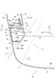
- FIG. 2 is a cross-sectional view taken along the line II-II shown in FIG.
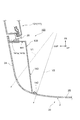
- FIG. 3 is a cross-sectional view showing a back door window mounting structure according to a modification.
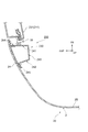
- FIG. 4 is a cross-sectional view showing a back door window mounting structure according to a modification.
- FIG. 1 is a perspective view showing a vehicle provided with a back door window mounting structure according to an embodiment of the present invention.
- FIG. 2 is a cross-sectional view taken along the line II-II shown in FIG. In the figure, the mounting structure 1 for the back door window 2 of this embodiment is applied to the rear portion of a vehicle 10.
- FIGS. 1 and 2 Note that an arrow FR appropriately shown in these drawings indicates the front side in the vehicle front-rear direction. An arrow UP indicates the upper side in the vehicle vertical direction. An arrow OUT indicates the outside in the vehicle width direction.
- a substantially rectangular luggage compartment 12 is provided at the rear end of the vehicle main body 11 of the vehicle 10 in the rear view of the vehicle.
- the vehicle main body 11 includes a roof panel 14 extending along the vehicle front-rear direction and the vehicle width direction on the upper portion of the vehicle, and a side outer panel 16 extending along the vehicle front-rear direction and the vehicle vertical direction on both sides in the vehicle width direction. And are arranged.
- the luggage compartment 12 of the vehicle main body 11 is opened and closed by a back door 20.
- the vehicle main body 11 includes a rear roof header (not shown) that is disposed on the vehicle inner side of the rear end portion of the roof panel 14 and that forms the periphery of the upper end of the luggage compartment 12.
- the back door 20 is supported by a hinge (not shown) attached to the rear roof header.
- the luggage compartment 12 is opened and closed by the back door 20 being rotated up and down around the hinge. That is, it is a flip-up type back door 20.
- the mounting structure 1 of the back door window 2 of this embodiment is applied to the back door 20.
- FIG. 2 is a cross-sectional view taken along the line II-II in FIG. 1 and shows the configuration of the end of the back door 20 in the vehicle width direction.
- the back door 20 is disposed on the door outer panel 24 (see FIG. 1) disposed on the door outer side (vehicle outer side) and the door lower side, and on the door inner side (vehicle inner side).
- a back door inner 30 (see FIG. 2).
- the back door inner 30 is provided with an opening 27, and the back door window 2 is attached so as to cover the opening 27.
- the back door inner 30 and the side wall 31 of the vehicle main body 11 face each other in the vehicle front-rear direction.
- the back door inner 30 is opposed to the rear end portion of the side wall portion 31.
- the side wall portion 31 includes a side outer panel 16 disposed on the outer side in the vehicle width direction (vehicle outer side), and side inner panels 33 and 34 disposed to face the side outer panel 16 on the inner side in the vehicle width direction (vehicle inner side).
- the connecting member 35 that connects the rear end portion of the side outer panel 16 and the rear end portions of the side inner panels 33 and 34, and the trim 36 that covers the side inner panel 34 from the inner side in the vehicle width direction are provided.
- a joint portion 37 is formed by joining the side inner panels 33 and 34 and the connection member 35.
- a seal portion 38 configured by a back door opening seal is provided. In a state where the back door 20 is closed, the space between the rear end portion of the side wall portion 31 of the vehicle main body portion 11 and the back door inner 30 is sealed by the seal portion 38. Details of the arrangement of the seal portion 38 will be described later.
- the back door window 2 is arranged along the vehicle width direction.
- the outer edge 2A in the vehicle width direction is curved and formed so as to go around the vehicle front side with respect to the vehicle width direction central portion 2B.
- the back door window 2 is arranged such that the outer edge 2 ⁇ / b> A in the vehicle width direction wraps around the side surface of the vehicle main body 11 in the vehicle plan view.
- the back door window 2 is configured to have a large degree of curvature of the outer peripheral surface of the edge 2A.
- the back door window 2 is made of resin, and for example, a material such as polypropylene resin is used.
- the attachment structure 1 for the back door window 2 is configured by attaching the back door window 2 to the back door inner 30.
- the back door inner 30 is disposed on the front front end portion (first end portion) 41 in the vehicle front-rear direction, the rear rear end portion (second end portion) 42, and on the inner side in the vehicle width direction. And an inner inner end (third end) 43.
- the front end 41 is disposed on the front side of the back door inner 30 and extends in the vehicle width direction.
- the rear side end portion 42 is disposed on the rear side of the back door inner 30 and extends in the vehicle width direction.
- the inner end portion 43 is disposed on the inner side in the vehicle width direction of the back door inner 30 and extends in the vehicle front-rear direction.
- the region 43a on the rear side of the inner end 43 is inclined outward in the vehicle width direction from the front side toward the rear side.
- the front end 41 is disposed on the front side of the back door inner 30 and extends in the vehicle width direction.
- the front end portion 41 includes a joint surface 41 a that is joined to the back door window 2, and a seal surface 41 b that contacts the seal portion 38.
- the joint surface 41a is disposed at a position shifted in the vehicle width direction with respect to the seal surface 41b.
- the joint surface 41a is disposed outside the seal surface 41b in the vehicle width direction. Further, a step is formed between the joint surface 41a and the seal surface 41b.
- the seal surface 41b is disposed on the rear side in the vehicle front-rear direction with respect to the joint surface 41a.
- the rear end portion 42 includes a joint surface 42 a that is joined to the back door window 2.
- a protruding portion 41d that protrudes forward is formed at a position where a step between the joining surface 41a and the sealing surface 41b is formed.
- the protrusion 41d protrudes forward from the seal surface 41b.
- a gap G1 is formed.
- a protrusion 41d is disposed on the back side of the gap G1. Accordingly, when water enters the gap G1 from the outside, the water is blocked by the protrusion 41d.
- the back door window 2 includes a first joint portion 51 that extends inward in the vehicle width direction, a second joint portion 52 that extends inward in the vehicle width direction, a first joint portion 51, and a second joint portion 52. Extending portion 53 extending along the back door window 2.
- the back door window 2 is joined to the front end 41 of the back door inner 30 via the first joint 51 and joined to the rear end 42 via the second joint 52. .
- the 1st junction part 51, the 2nd junction part 52, and the extension part 53 may be formed by the back door window 2 and 2 color molding.
- Two-color molding means that two different color materials or two different materials are bonded together in a molding process so that two different color materials or two different materials coexist in one molded product. It is a molding method.
- the first joint 51 is disposed near the front end 2a of the edge 2A of the back door window 2.
- a front surface of the first joint portion 51 is configured as a joint surface 51 a that is joined to the front end portion 41 of the back door inner 30.
- the joint surface 51a of the first joint portion 51 contacts the joint surface 41a of the front end portion 41 of the back door inner 30, and is joined by an adhesive.
- the second joint portion 52 is disposed at a position that is separated from the first joint portion 51 toward the rear side in the vehicle front-rear direction.
- the second joint portion 52 extends more inward in the vehicle width direction than the first joint portion 51.
- a front surface of the second joint portion 52 is configured as a joint surface 52 a that is joined to the rear end portion 42 of the back door inner 30.
- the joint surface 52a of the second joint portion 52 contacts the joint surface 42a of the rear side end portion 42 of the back door inner 30, and is joined by an adhesive.
- the extending portion 53 extends in the vehicle front-rear direction along the edge 2 ⁇ / b> A of the back door window 2.
- the extending portion 53 is connected to the outer end portion of the first joint portion 51 in the vehicle width direction and the outer end portion of the second joint portion 52 in the vehicle width direction.
- the first joint portion 51 is disposed outside the rear end portion 42 of the back door inner 30 in the vehicle width direction. That is, the inner end portion 51 b of the first joint portion 51 is disposed outside the outer end portion 42 b of the rear end portion 42 of the back door inner 30.
- a gap G2 is formed between the end 51b of the first joint 51 and the end 42b of the rear end 42 in the vehicle width direction.
- the position where the adhesive is applied to the joint surface 51a of the first joint 51 is more outward in the vehicle width direction than the position where the adhesive is applied to the joint surface 52a of the second joint 52. Be placed.
- the back door window 2 is joined to the front end portion 41 of the back door inner 30 via the first joining portion 51 that extends inward of the vehicle. Is done.
- the back door window 2 is joined to the rear end 42 of the back door inner 30.
- the back door window 2 is supported by both the front end 41 and the rear end 42 of the back door inner 30 to form a closed cross section. As described above, the attachment strength of the back door window 2 to the back door inner 30 can be improved.
- the back door window 2 extends to the inside of the vehicle and is disposed on the rear side in the vehicle front-rear direction with respect to the first joint portion 51. Is provided.
- the back door window 2 is joined to the rear end portion 42 via the second joint portion 52.
- the first joint portion 51 is disposed on the vehicle outer side than the rear end portion 42 of the back door inner 30.
- the back door window 2 can be joined to the rear end portion 42 of the back door inner 30 via the second joint portion 52, thereby improving the joint strength.
- the first joint portion 51 is disposed on the vehicle outer side than the rear end portion 42 of the back door inner 30. Therefore, when attaching the back door window 2 to the back door inner 30, it can prevent that the 1st junction part 51 interferes with the rear side edge part 42.
- the vehicle main body 11 and the back door inner 30 are opposed to each other in the vehicle front-rear direction.
- the space between the vehicle main body 11 and the back door inner 30 is sealed by a seal portion 38.
- the joint surface 51a of the first joint portion 51 with respect to the back door inner 30 is disposed at a position shifted in the vehicle width direction with respect to the seal surface 41b in contact with the seal portion 38.
- a step is formed between the joint surface 41a and the seal surface 41b.
- the seal surface 41b is disposed on the rear side in the vehicle front-rear direction with respect to the joint surface 41a.
- the back door inner 30 includes an inner end 43 that is disposed on the vehicle inner side and extends in the vehicle front-rear direction. A region on the rear side of the inner end 43 is inclined outward from the front toward the rear. With such a configuration, a wide field of view from the inside of the vehicle body can be secured. For example, assuming that the field of view when the length of the back door window 2 extends rearward as shown in FIG. 3 is V2, in this embodiment, the field of view reaches V1, as shown in FIG. Can be spread.
- the second joint portion 52 is provided at the edge portion 2A of the back door window 2, but may be further provided at the rear side.
- the inner end 143 of the back door inner 130 extends to the rear side of the back door window 2, and the rear end 142 is joined at the vehicle width direction central portion 2B. Further, the back door window 2 is directly joined to the rear end 142 of the back door inner 130 without going through the second joint.
- the vehicle width direction central portion 2B which is a joined portion, is attached in the mounting direction of the back door window 2 ( Therefore, the rear end 142 of the back door inner 130 can be joined with sufficient joining strength.
- the field of view V2 from the inside of the vehicle is narrower than the field of view V1 of the mounting structure 1 shown in FIG.
- the joint surface 141a and the seal surface 141b of the front end 141 are provided at substantially the same position. Even in such a case, sealing performance can be ensured.
- the joining surface 141a and the seal surface 141b are arranged at a shifted position, so that the smoothness of the seal surface 141b can be maintained. Compared with this, the sealing performance can be improved.
- the rear end 242 of the back door inner 230 (the bent portion 245 provided at the rear end 242) is joined at the edge 2A. Further, the back door window 2 is directly joined to the rear end 242 of the back door inner 230 without going through the second joint.
- the edge 2A has a small inclination with respect to the mounting direction of the back door window 2 (the direction from the rear side of the vehicle toward the front side), there is a possibility that the bonding may be insufficient. Therefore, the mounting structure 1 and the mounting structure 100 of FIG. This configuration can ensure the bonding strength.
- SYMBOLS 1 Mounting structure (back door window mounting structure), 2 ... Back door window, 10 ... Vehicle, 11 ... Vehicle main-body part, 20 ... Back door, 30, 130, 230 ... Back door inner, 41 ... Front side edge part ( First end part), 42 ... Rear end part (second end part), 43 ... Inner end part (third end part), 51 ... First joint part, 52 ... Second joint part.
Landscapes
- Engineering & Computer Science (AREA)
- Mechanical Engineering (AREA)
- Window Of Vehicle (AREA)
- Seal Device For Vehicle (AREA)
Abstract
バックドアウィンドウ2は、バックドアインナ30の前側端部41に対して、車幅方向における内側へ延びる第1の接合部51を介して接合される。それに加え、バックドアウィンドウ2は、バックドアインナ30の後側端部42に対して接合される。このような構造により、バックドアウィンドウ2が、バックドアインナ30の前側端部41と後側端部42の両方で支持される。以上により、バックドアインナ30に対するバックドアウィンドウ2の取付強度を向上できる。
Description
本発明は、バックドアウィンドウの取付構造に関する。
従来のバックドアウィンドウの取付構造として、例えば特許文献1に記載されている技術が知られている。特許文献1に記載のバックドアウィンドウの取付構造では、バックドアウィンドウの前側に、車幅方向における内側へ延びる接合部が設けられている。バックドアウィンドウは、接合部を介してバックドアインナの前側の端部に対して接合される。
ここで、上述のようなバックドアウィンドウの取付構造においては、バックドアインナに対するバックドアウィンドウの取付強度を向上させることが求められていた。
そこで、本発明は、バックドアインナに対するバックドアウィンドウの取付強度を向上させることができるバックドアウィンドウの取付構造を提供することを目的とする。
本発明の一側面に係るバックドアウィンドウの取付構造は、バックドアウィンドウをバックドアのバックドアインナへ取り付けることによって構成されるバックドアウィンドウの取付構造であって、バックドアインナは、車両前後方向における前側の第1の端部及び、後側の第2の端部を備え、バックドアウィンドウは、車両内側へ延びる第1の接合部を備え、バックドアウィンドウは、第1の端部に対して第1の接合部を介して接合され、第2の端部に対して接合される。
本発明の一側面に係るバックドアウィンドウの取付構造によれば、バックドアウィンドウは、バックドアインナの前側の第1の端部に対して、車両内側へ延びる第1の接合部を介して接合される。それに加え、バックドアウィンドウは、バックドアインナの後側の第2の端部に対して接合される。このような構造により、バックドアウィンドウが、バックドアインナの前側の第1の端部と後側の第2の端部の両方で支持される。以上により、バックドアインナに対するバックドアウィンドウの取付強度を向上できる。
本発明の他の側面に係るバックドアウィンドウの取付構造において、バックドアウィンドウは、車両内側へ延び、第1の接合部よりも車両前後方向における後側に配置される第2の接合部を備え、バックドアウィンドウは、第2の端部に対して第2の接合部を介して接合され、第1の接合部は、バックドアインナの第2の端部よりも車両外側に配置されてよい。このような構成により、バックドアウィンドウは、バックドアインナの後側の第2の端部に対して、第2の接合部を介して接合されることで、接合強度を向上できる。また、第1の接合部は、バックドアインナの第2の端部よりも車両外側に配置されている。従って、バックドアウィンドウをバックドアインナに取り付ける際に、第1の接合部が第2の端部と干渉することを防止できる。
本発明の他の側面に係るバックドアウィンドウの取付構造において、車両本体部とバックドアインナとは、車両前後方向に対向し、車両本体部とバックドアインナとの間は、シール部によって封止され、第1の接合部のバックドアインナに対する接合面は、シール部と接触するシール面に対して車両外側にずれた位置に配置されてよい。このような構造により、シール部によるシール面と接合面とを離れた位置に配置することができるため、シール面でのシール性を向上できる。
本発明の他の側面に係るバックドアウィンドウの取付構造において、接合面と、シール面との間には段差が形成され、シール面は、接合面よりも車両前後方向における後側に配置されてよい。このような構成により、車両本体部と接合面との間の隙間から水が入り込んだ場合に、シール面に直接水がかかることを防止できる。
本発明の他の側面に係るバックドアウィンドウの取付構造において、バックドアインナは、車両内側に配置されて、車両前後方向に延びる第3の端部を備え、第3の端部の後側の領域は、前側から後側へ向かって車両外側へ傾斜してよい。このような構成により、車体内部からの視野を広く確保することができる。
本発明によれば、バックドアインナに対するバックドアウィンドウの取付強度を向上できる。
以下、本発明の実施形態について、図面を参照して詳細に説明する。なお、図面において、同一または同等の要素には同じ符号を付し、重複する説明を省略する。
図1は、本発明の実施形態に係るバックドアウィンドウの取付構造を備えた車両を示す斜視図である。図2は、図1に示すII-II線に沿った断面図である。同図において、本実施形態のバックドアウィンドウ2の取付構造1は、車両10の後部に適用されている。
以下、図1及び図2を用いて、本発明に係るバックドアウィンドウ2の取付構造1の実施形態について説明する。なお、これらの図において適宜示される矢印FRは車両前後方向における前側を示している。矢印UPは車両上下方向における上側を示している。矢印OUTは車幅方向における外側を示している。
図1に示されるように、車両10の車両本体部11の後端部には、車両背面視にて略矩形状の荷室12が設けられている。車両本体部11には、車両上部に車両前後方向及び車幅方向に沿って延在するルーフパネル14と、車幅方向両サイドに車両前後方向及び車両上下方向に沿って延在するサイドアウタパネル16と、が配設されている。
車両本体部11の荷室12は、バックドア20によって開閉される。車両本体部11は、ルーフパネル14の後端部の車両内側に配置されて荷室12の上端周りを構成するリアルーフヘッダ(図示省略)を備えている。バックドア20は、リアルーフヘッダに取り付けられたヒンジ(図示省略)によって支持されている。バックドア20がヒンジを中心にして上下方向に回転されることで、荷室12が開閉される。つまり、跳ね上げ式のバックドア20となっている。このバックドア20に本実施形態のバックドアウィンドウ2の取付構造1が適用されている。
図2には、図1中のII-II線に沿った断面図であって、バックドア20の車幅方向端部の構成が示されている。なお、図2では、バックドア20の車幅方向の一方の端部のみが図示されている。バックドア20の車幅方向端部は左右対称であるので、バックドア20の車幅方向の他方の端部は図示を省略する。図1及び図2に示されるように、バックドア20は、ドア外側(車両外側)及びドア下部側に配置されたドアアウタパネル24(図1参照)と、ドア内側(車両内側)に配置されたバックドアインナ30(図2参照)と、を備えている。バックドアインナ30には開口部27が設けられており、開口部27を覆うようにバックドアウィンドウ2が取り付けられている。
バックドアインナ30と車両本体部11の側壁部31は、車両前後方向に対向する。バックドアインナ30は、側壁部31の後端部と対向している。側壁部31は、車幅方向外側(車両外側)に配置されるサイドアウタパネル16と、当該サイドアウタパネル16と車幅方向内側(車両内側)で対向するように配置されるサイドインナパネル33,34と、サイドアウタパネル16の後端部とサイドインナパネル33,34の後端部とを接続する接続部材35と、サイドインナパネル34を車幅方向内側から覆うトリム36と、を備える。側壁部31の後端部には、サイドインナパネル33,34及び接続部材35を接合させた接合部37が形成される。側壁部31の後端部とバックドアインナ30との間には、バックドアオープンニングシールによって構成されるシール部38が設けられている。バックドア20が閉じた状態では、車両本体部11の側壁部31の後端部とバックドアインナ30との間は、シール部38によって封止される。なお、シール部38の配置の詳細については後述する。
バックドアウィンドウ2は、車幅方向に沿って配置されている。車両平面視にて車幅方向外側の縁部2Aが車幅方向中央部2Bよりも車両前側に廻り込むように湾曲して形成されている。言い換えると、バックドアウィンドウ2は、車両平面視にて車幅方向外側の縁部2Aが車両本体部11の側面側に廻り込むように配置されている。バックドアウィンドウ2は、縁部2Aの外周面の湾曲度合いが大きい構成とされている。バックドアウィンドウ2は、樹脂製であり、例えば、ポリプロピレン樹脂等の材質が用いられる。
次に、本実施形態に係るバックドアウィンドウ2の取付構造1について図2を参照して詳細に説明する。図2に示すように、バックドアウィンドウ2の取付構造1は、バックドアウィンドウ2をバックドアインナ30へ取り付けることによって構成される。
バックドアインナ30は、車両前後方向における前側の前側端部(第1の端部)41と、後側の後側端部(第2の端部)42と、車幅方向における内側に配置される内側の内側端部(第3の端部)43と、を備える。前側端部41は、バックドアインナ30の前側に配置されて車幅方向に延びている。後側端部42は、バックドアインナ30の後側に配置されて車幅方向に延びている。内側端部43は、バックドアインナ30の車幅方向における内側に配置されて車両前後方向に延びている。内側端部43の後側の領域43aは、前側から後側へ向かって車幅方向外側へ傾斜する。
前側端部41は、バックドアインナ30の前側に配置されて車幅方向に延びている。前側端部41は、バックドアウィンドウ2と接合される接合面41aと、シール部38と接触するシール面41bと、を備える。接合面41aは、シール面41bに対して車幅方向にずれた位置に配置される。接合面41aは、シール面41bよりも車幅方向における外側に配置される。また、接合面41aと、シール面41bとの間には段差が形成される。シール面41bは、接合面41aよりも車両前後方向における後側に配置される。後側端部42は、バックドアウィンドウ2と接合される接合面42aを備える。
接合面41aとシール面41bとの間の段差が形成される位置には、前方へ突出する突出部41dが形成されている。突出部41dは、シール面41bよりも前側へ突出している。バックドアインナ30の前側端部41のうち、接合面41aに対応する部分(及び、後述のバックドアウィンドウ2の前端部2a)と、車両本体部11の側壁部31の後端部との間には、隙間G1が形成される。車幅方向における外側から内側へ向って見たときに、隙間G1の奥側には、突出部41dが配置されている。従って、外部から隙間G1内へ水が浸入した場合、当該水は突出部41dによって堰き止められる。
バックドアウィンドウ2は、車幅方向における内側へ延びる第1の接合部51と、車幅方向における内側へ延びる第2の接合部52と、第1の接合部51と第2の接合部52との間でバックドアウィンドウ2に沿って延びる延在部53と、を備える。バックドアウィンドウ2は、バックドアインナ30の前側端部41に対して第1の接合部51を介して接合され、後側端部42に対して第2の接合部52を介して接合される。第1の接合部51、第2の接合部52、及び延在部53は、バックドアウィンドウ2と2色成形によって形成されてよい。2色成形とは、色の異なる2つの同種材料、または材質の異なる2種類の材料を成形工程で接着させることにより、互いに異なる2色の材料または2種類の材料を1つの成形品に共存させる成形法である。
第1の接合部51は、バックドアウィンドウ2の縁部2Aの前端部2a付近に配置されている。第1の接合部51の前側の面は、バックドアインナ30の前側端部41と接合される接合面51aとして構成される。第1の接合部51の接合面51aは、バックドアインナ30の前側端部41の接合面41aと接触し、接着剤によって接合される。第2の接合部52は、第1の接合部51よりも車両前後方向における後側に離間する位置に配置されている。第2の接合部52は、第1の接合部51よりも車幅方向における内側へ延びる。第2の接合部52の前側の面は、バックドアインナ30の後側端部42と接合される接合面52aとして構成される。第2の接合部52の接合面52aは、バックドアインナ30の後側端部42の接合面42aと接触し、接着剤によって接合される。延在部53は、バックドアウィンドウ2の縁部2Aに沿って車両前後方向に延びている。延在部53は、第1の接合部51の車幅方向における外側の端部と、第2の接合部52の車幅方向における外側の端部とに接続される。
第1の接合部51は、バックドアインナ30の後側端部42よりも車幅方向における外側に配置される。すなわち、第1の接合部51の内側の端部51bは、バックドアインナ30の後側端部42の外側の端部42bよりも外側に配置される。第1の接合部51の端部51bと後側端部42の端部42bとの間には、車幅方向において隙間G2が形成される。第1の接合部51の接合面51aに対して接着剤が塗布される位置は、第2の接合部52の接合面52aに対して接着剤が塗布される位置よりも車幅方向における外側に配置される。
次に、本実施形態に係るバックドアウィンドウ2の取付構造1の作用・効果について説明する。
本実施形態に係るバックドアウィンドウ2の取付構造1によれば、バックドアウィンドウ2は、バックドアインナ30の前側端部41に対して、車両内側へ延びる第1の接合部51を介して接合される。それに加え、バックドアウィンドウ2は、バックドアインナ30の後側端部42に対して接合される。このような構造により、バックドアウィンドウ2が、バックドアインナ30の前側端部41と後側端部42の両方で支持され、閉じ断面を形成する。以上により、バックドアインナ30に対するバックドアウィンドウ2の取付強度を向上できる。
本実施形態に係るバックドアウィンドウ2の取付構造1において、バックドアウィンドウ2は、車両内側へ延び、第1の接合部51よりも車両前後方向における後側に配置される第2の接合部52を備える。バックドアウィンドウ2は、後側端部42に対して第2の接合部52を介して接合される。また、第1の接合部51は、バックドアインナ30の後側端部42よりも車両外側に配置されている。このような構成により、バックドアウィンドウ2は、バックドアインナ30の後側端部42に対して、第2の接合部52を介して接合されることで、接合強度を向上できる。また、第1の接合部51は、バックドアインナ30の後側端部42よりも車両外側に配置されている。従って、バックドアウィンドウ2をバックドアインナ30に取り付ける際に、第1の接合部51が後側端部42と干渉することを防止できる。
本実施形態に係るバックドアウィンドウ2の取付構造1において、車両本体部11とバックドアインナ30とは、車両前後方向に対向している。車両本体部11とバックドアインナ30との間は、シール部38によって封止されている。第1の接合部51のバックドアインナ30に対する接合面51aは、シール部38と接触するシール面41bに対して車幅方向にずれた位置に配置されている。このような構造により、シール部38によるシール面41bと接合面41a(接着剤の塗布により面の平滑性に影響が及ぼされる)とを離れた位置に配置することができるため、シール面41bでのシール性を向上できる。なお、このようにシール面41bを接合面51aから離れた位置に配置する場合、シール面41bに作用するモーメントが大きくなる。しかし、バックドアウィンドウ2が、バックドアインナ30の後側端部42に対しても接合されているため、当該モーメントを支えることができるのでシール性を確保することができる。
本実施形態に係るバックドアウィンドウ2の取付構造1において、接合面41aと、シール面41bとの間には段差が形成される。シール面41bは、接合面41aよりも車両前後方向における後側に配置されている。このような構成により、車両本体部11と接合面41aとの間の隙間G1から水が入り込んだ場合に、シール面41bに直接水がかかることを防止できる。
本実施形態に係るバックドアウィンドウ2の取付構造1において、バックドアインナ30は、車両内側に配置されて、車両前後方向に延びる内側端部43を備える。内側端部43の後側の領域は、前側から後側へ向かって車両外側へ傾斜している。このような構成により、車体内部からの視野を広く確保することができる。例えば、図3に示すようにバックドアウィンドウ2の長さが後方へ向かって延びるような形状であった場合の視野をV2とすると、本実施形態では図2に示すように、視野をV1まで広げることができる。
以上、本発明の種々の実施形態について説明したが、本発明は上記実施形態に限定されるものではなく、各請求項に記載した要旨を変更しない範囲で変形し、又は他のものに適用したものであってもよい。
例えば、上述の実施形態では、バックドアウィンドウ2の縁部2Aに第2の接合部52が設けられていたが、更に後側に設けられていてもよい。
例えば、図3に示すバックドアウィンドウ2の取付構造100を採用してもよい。この取付構造100は、バックドアインナ130の内側端部143がバックドアウィンドウ2の後側まで延びており、後側端部142が車幅方向中央部2Bにて接合されている。また、バックドアウィンドウ2は、第2の接合部を介することなく、直接バックドアインナ130の後側端部142に接合されている。
このように、バックドアウィンドウ2がバックドアインナ130の後側端部142に直接接合される場合であっても、接合部分である車幅方向中央部2Bは、バックドアウィンドウ2の取付方向(車両後側から前側へ向かう方向)に対する傾きが小さいため、十分な接合強度で、バックドアインナ130の後側端部142を接合できる。なお、このようなバックドアウィンドウ2の取付構造100では、車両内部からの視野V2が、図2に示す取付構造1の視野V1に比して狭くなる。また、取付構造100では、前側端部141の接合面141aとシール面141bが略同位置に設けられている。このような場合であってもシール性を確保できる。ただし、図2に示す取付構造1では、接合面141aとシール面141bが、ずれた位置に配置されているため、シール面141bの平滑性を維持することができるため、取付構造100の構成に比してシール性を高めることができる。
例えば、図4に示すバックドアウィンドウ2の取付構造200を採用してもよい。この取付構造200は、バックドアインナ230の後側端部242(後側端部242に設けられた屈曲部245)が縁部2Aにて接合されている。また、バックドアウィンドウ2は、第2の接合部を介することなく、直接バックドアインナ230の後側端部242に接合されている。ただし、縁部2Aはバックドアウィンドウ2の取付方向(車両後側から前側へ向かう方向)に対する傾きが小さいため接着が不十分になる可能性もあるため、図2の取付構造1や取付構造100の構成の方が、接合強度を確保できる。
1…取付構造(バックドアウィンドウの取付構造)、2…バックドアウィンドウ、10…車両、11…車両本体部、20…バックドア、30,130,230…バックドアインナ、41…前側端部(第1の端部)、42…後側端部(第2の端部)、43…内側端部(第3の端部)、51…第1の接合部、52…第2の接合部。
Claims (5)
- バックドアウィンドウをバックドアのバックドアインナへ取り付けることによって構成されるバックドアウィンドウの取付構造であって、
前記バックドアインナは、車両前後方向における前側の第1の端部及び、後側の第2の端部を備え、
前記バックドアウィンドウは、車両内側へ延びる第1の接合部を備え、
前記バックドアウィンドウは、前記第1の端部に対して前記第1の接合部を介して接合され、前記第2の端部に対して接合される、バックドアウィンドウの取付構造。 - 前記バックドアウィンドウは、前記車両内側へ延び、前記第1の接合部よりも前記車両前後方向における後側に配置される第2の接合部を備え、
前記バックドアウィンドウは、前記第2の端部に対して前記第2の接合部を介して接合され、
前記第1の接合部は、前記バックドアインナの前記第2の端部よりも車両外側に配置される、請求項1に記載のバックドアウィンドウの取付構造。 - 車両本体部と前記バックドアインナとは、前記車両前後方向に対向し、
前記車両本体部と前記バックドアインナとの間は、シール部によって封止され、
前記第1の接合部の前記バックドアインナに対する接合面は、前記シール部と接触するシール面に対して車両外側にずれた位置に配置される、請求項1又は2に記載のバックドアウィンドウの取付構造。 - 前記接合面と、前記シール面との間には段差が形成され、
前記シール面は、前記接合面よりも前記車両前後方向における後側に配置される、請求項3に記載のバックドアウィンドウの取付構造。 - 前記バックドアインナは、前記車両内側に配置されて、前記車両前後方向に延びる第3の端部を備え、
前記第3の端部の後側の領域は、前側から後側へ向かって車両外側へ傾斜する、請求項1~4の何れか一項に記載のバックドアウィンドウの取付構造。
Applications Claiming Priority (2)
| Application Number | Priority Date | Filing Date | Title |
|---|---|---|---|
| JP2015050389A JP5943111B1 (ja) | 2015-03-13 | 2015-03-13 | バックドアウィンドウの取付構造 |
| JP2015-050389 | 2015-03-13 |
Publications (1)
| Publication Number | Publication Date |
|---|---|
| WO2016147831A1 true WO2016147831A1 (ja) | 2016-09-22 |
Family
ID=56244717
Family Applications (1)
| Application Number | Title | Priority Date | Filing Date |
|---|---|---|---|
| PCT/JP2016/055598 Ceased WO2016147831A1 (ja) | 2015-03-13 | 2016-02-25 | バックドアウィンドウの取付構造 |
Country Status (2)
| Country | Link |
|---|---|
| JP (1) | JP5943111B1 (ja) |
| WO (1) | WO2016147831A1 (ja) |
Citations (4)
| Publication number | Priority date | Publication date | Assignee | Title |
|---|---|---|---|---|
| JPH06219152A (ja) * | 1993-01-25 | 1994-08-09 | Honda Motor Co Ltd | 窓用曲面ガラスの組み付け方法および窓用曲面ガラス |
| JPH079614U (ja) * | 1993-07-22 | 1995-02-10 | 株式会社ニフコ | 自動車用窓ガラスの取付構造 |
| JPH09254645A (ja) * | 1996-03-21 | 1997-09-30 | Suzuki Motor Corp | 自動車用ウインドガラスの取付構造 |
| JP2013018346A (ja) * | 2011-07-11 | 2013-01-31 | Toyota Motor Corp | 接着ガラスの取付構造 |
-
2015
- 2015-03-13 JP JP2015050389A patent/JP5943111B1/ja not_active Expired - Fee Related
-
2016
- 2016-02-25 WO PCT/JP2016/055598 patent/WO2016147831A1/ja not_active Ceased
Patent Citations (4)
| Publication number | Priority date | Publication date | Assignee | Title |
|---|---|---|---|---|
| JPH06219152A (ja) * | 1993-01-25 | 1994-08-09 | Honda Motor Co Ltd | 窓用曲面ガラスの組み付け方法および窓用曲面ガラス |
| JPH079614U (ja) * | 1993-07-22 | 1995-02-10 | 株式会社ニフコ | 自動車用窓ガラスの取付構造 |
| JPH09254645A (ja) * | 1996-03-21 | 1997-09-30 | Suzuki Motor Corp | 自動車用ウインドガラスの取付構造 |
| JP2013018346A (ja) * | 2011-07-11 | 2013-01-31 | Toyota Motor Corp | 接着ガラスの取付構造 |
Also Published As
| Publication number | Publication date |
|---|---|
| JP5943111B1 (ja) | 2016-06-29 |
| JP2016168945A (ja) | 2016-09-23 |
Similar Documents
| Publication | Publication Date | Title |
|---|---|---|
| JP6700979B2 (ja) | 自動車ドア用グラスラン | |
| US20130219799A1 (en) | Glass run integral molding and door frame structure | |
| JP6254428B2 (ja) | 樹脂パネル及びその製造方法 | |
| CN108146208A (zh) | 车身结构 | |
| JP2016203893A (ja) | ガラスランの固定構造 | |
| JP6059925B2 (ja) | ドアウエザストリップ | |
| JP2009067167A (ja) | 車両の車体後部構造 | |
| JP4930788B2 (ja) | ドアウエザストリップ | |
| JP6243250B2 (ja) | 車両用ドア | |
| JP5690242B2 (ja) | 自動車用ドア構造 | |
| JP5943111B1 (ja) | バックドアウィンドウの取付構造 | |
| JP2005043367A (ja) | 圧力センサを備えたセンサ構成群のケーシング用カバー | |
| JP5912542B2 (ja) | 車体のパネル構造 | |
| JP5773590B2 (ja) | ウェザストリップ | |
| JP6171668B2 (ja) | サンルーフのパネル構造 | |
| JP6912949B2 (ja) | パーティングシール | |
| JP2018043630A (ja) | サンルーフのパネル構造 | |
| JP2016199097A (ja) | バックドアウィンドウの取付構造 | |
| JP6567913B2 (ja) | 車両のバックドア | |
| JP6606401B2 (ja) | 自動車用シート部材 | |
| JP6434325B2 (ja) | ウェザストリップ | |
| CN103982341B (zh) | 空气过滤器 | |
| JP6338147B2 (ja) | 車両ドア開口部構造 | |
| JP6825019B2 (ja) | 車体側部構造 | |
| WO2012066629A1 (ja) | ランプユニット嵌め込み部のシール構造 |
Legal Events
| Date | Code | Title | Description |
|---|---|---|---|
| 121 | Ep: the epo has been informed by wipo that ep was designated in this application |
Ref document number: 16764661 Country of ref document: EP Kind code of ref document: A1 |
|
| NENP | Non-entry into the national phase |
Ref country code: DE |
|
| 122 | Ep: pct application non-entry in european phase |
Ref document number: 16764661 Country of ref document: EP Kind code of ref document: A1 |