WO2016147685A1 - 水陸両用車 - Google Patents
水陸両用車 Download PDFInfo
- Publication number
- WO2016147685A1 WO2016147685A1 PCT/JP2016/050646 JP2016050646W WO2016147685A1 WO 2016147685 A1 WO2016147685 A1 WO 2016147685A1 JP 2016050646 W JP2016050646 W JP 2016050646W WO 2016147685 A1 WO2016147685 A1 WO 2016147685A1
- Authority
- WO
- WIPO (PCT)
- Prior art keywords
- water
- unit
- cooling source
- amphibious vehicle
- opening
- Prior art date
- Legal status (The legal status is an assumption and is not a legal conclusion. Google has not performed a legal analysis and makes no representation as to the accuracy of the status listed.)
- Ceased
Links
Images


Classifications
-
- B—PERFORMING OPERATIONS; TRANSPORTING
- B60—VEHICLES IN GENERAL
- B60F—VEHICLES FOR USE BOTH ON RAIL AND ON ROAD; VEHICLES CAPABLE OF TRAVELLING IN OR ON DIFFERENT MEDIA, e.g. AMPHIBIOUS VEHICLES
- B60F3/00—Amphibious vehicles, i.e. vehicles capable of travelling both on land and on water; Land vehicles capable of travelling under water
-
- B—PERFORMING OPERATIONS; TRANSPORTING
- B60—VEHICLES IN GENERAL
- B60F—VEHICLES FOR USE BOTH ON RAIL AND ON ROAD; VEHICLES CAPABLE OF TRAVELLING IN OR ON DIFFERENT MEDIA, e.g. AMPHIBIOUS VEHICLES
- B60F3/00—Amphibious vehicles, i.e. vehicles capable of travelling both on land and on water; Land vehicles capable of travelling under water
- B60F3/003—Parts or details of the vehicle structure; vehicle arrangements not otherwise provided for
- B60F3/0053—Particular devices for gas circulation, e.g. air admission, cooling, watertightness
-
- B—PERFORMING OPERATIONS; TRANSPORTING
- B63—SHIPS OR OTHER WATERBORNE VESSELS; RELATED EQUIPMENT
- B63H—MARINE PROPULSION OR STEERING
- B63H11/00—Marine propulsion by water jets
- B63H11/02—Marine propulsion by water jets the propulsive medium being ambient water
- B63H11/04—Marine propulsion by water jets the propulsive medium being ambient water by means of pumps
- B63H11/08—Marine propulsion by water jets the propulsive medium being ambient water by means of pumps of rotary type
-
- B—PERFORMING OPERATIONS; TRANSPORTING
- B60—VEHICLES IN GENERAL
- B60F—VEHICLES FOR USE BOTH ON RAIL AND ON ROAD; VEHICLES CAPABLE OF TRAVELLING IN OR ON DIFFERENT MEDIA, e.g. AMPHIBIOUS VEHICLES
- B60F3/00—Amphibious vehicles, i.e. vehicles capable of travelling both on land and on water; Land vehicles capable of travelling under water
- B60F3/0007—Arrangement of propulsion or steering means on amphibious vehicles
- B60F3/0015—Arrangement of propulsion or steering means on amphibious vehicles comprising tracks specially adapted therefor
-
- B—PERFORMING OPERATIONS; TRANSPORTING
- B63—SHIPS OR OTHER WATERBORNE VESSELS; RELATED EQUIPMENT
- B63H—MARINE PROPULSION OR STEERING
- B63H11/00—Marine propulsion by water jets
- B63H11/02—Marine propulsion by water jets the propulsive medium being ambient water
- B63H11/04—Marine propulsion by water jets the propulsive medium being ambient water by means of pumps
- B63H11/08—Marine propulsion by water jets the propulsive medium being ambient water by means of pumps of rotary type
- B63H2011/081—Marine propulsion by water jets the propulsive medium being ambient water by means of pumps of rotary type with axial flow, i.e. the axis of rotation being parallel to the flow direction
Definitions
- the present invention relates to an amphibious vehicle.
- This application claims priority based on Japanese Patent Application No. 2015-056031 filed in Japan on March 19, 2015, the contents of which are incorporated herein by reference.
- An amphibious vehicle includes, for example, a power source engine, power transmission means for transmitting driving force from the engine, land traveling means, and surface navigation means.
- the power transmission means is a propeller shaft that transmits driving force from the engine.
- the land traveling means is a wheel or a crawler track that is driven by a driving force transmitted from the engine via the power transmission means.
- the water navigation means is a water jet mechanism or a screw that is switched from the land traveling means and is driven by the driving force from the engine.
- An amphibious vehicle hull (vehicle main body) disclosed in Patent Document 1 has a double bottom structure including a first ship bottom and a second ship bottom.
- a gear box such as a propeller shaft and a differential gear is installed in a space between the first ship bottom and the second ship bottom. The space is open at the front and rear of the hull.
- the amphibious vehicle disclosed in Patent Document 2 includes a vehicle body, a water jet mechanism, and a water-cooled heat exchanger.
- the water jet mechanism includes a water jet water passage and a propulsion device including an impeller and a shaft.
- the water jet passage has an intake port formed on the bottom surface of the vehicle body and a discharge port formed on the rear surface of the vehicle body.
- the impeller of the propulsion device is provided in the water jet water passage.
- the shaft of the propeller transmits the driving force of the engine to the impeller.
- the feather bear is driven by the power of the engine, takes in water from the intake during water navigation, and discharges water as a water jet from the outlet.
- the amphibious vehicle of Patent Document 2 has a cooling water passage for sending water to a water-cooled heat exchanger.
- the cooling water passage has a cooling intake opening that opens in the water jet water passage and on the outlet side of the impeller.
- water from the cooling water passage, engine cooling water, hydraulic oil, and the like are cooled by a water-cooled heat exchanger.
- Amphibious vehicles travel on land as well as sail on the water. Furthermore, amphibious vehicles may land on land from water. Thus, amphibious vehicles have various forms as movement forms. For this reason, it is desirable for amphibious vehicles to stably cool the power section in each movement mode.
- an object of the present invention is to provide an amphibious vehicle in which the power section is stably cooled.
- An amphibious vehicle as a first embodiment according to the invention for achieving the above object is A vehicle main body, a traveling unit for causing the vehicle main body to travel on land, a propulsion unit for generating a propulsive force in water and navigating the vehicle main body on water, and power for the traveling unit and the propulsion unit A power unit to be applied, and a cooling unit to cool at least the power unit, wherein the cooling unit takes in air as a cooling source from the outside, and takes in water as a cooling source from the outside.
- a second cooling source introduction part, the second cooling source introduction part has an opening for taking in water, and the opening is on the rear side of the center of gravity of the entire vehicle body and the outer surface of the vehicle body Open in the flooded area.
- the amphibious vehicle can take in water from the second cooling source introduction section of the cooling section during water navigation that requires high output, and can cool the power section and the like using this water as a cooling source.
- the opening for taking in water from the second cooling source introduction portion is provided behind the center of gravity of the entire vehicle body and in the flooded portion of the outer surface of the vehicle body. For this reason, in the amphibious vehicle, when landing, even when the vehicle body is in an inclined posture in which the front portion of the vehicle body is arranged upward and the rear portion is arranged downward, the opening can be positioned in water, that is, long During (for example, until the end), the opening can be positioned in the water and water can be continuously taken in. Therefore, in the amphibious vehicle, even when the vehicle body is in an inclined posture as described above at the time of landing, the power unit and the like can be effectively cooled using the water taken from the second cooling source introduction unit as a cooling source. Can do.
- the propulsion unit is a water jet mechanism that generates a water jet as a propulsive force
- the water jet mechanism includes a water jet water channel through which water flows and the water jet water channel.
- An impeller disposed inside and rotating with power from the power unit, and the water jet water passage has an introduction port for taking water from outside, and the introduction port of the water jet water passage and the The opening of the second cooling source introduction part is disposed at a different position on the outer surface of the vehicle body, and the second cooling source introduction part is a passage independent of the water jet water passage.
- the second cooling source introduction part is an independent passage with respect to the water jet passage, the cleaning liquid is introduced into the second cooling source introduction part without being disturbed by the impeller in the water jet passage. Can be easily supplied. For example, a jet of cleaning liquid can be sent to the back of the second cooling source introduction part. Therefore, in the amphibious vehicle, the inside of the second cooling source introduction part can be easily cleaned with the cleaning liquid.
- an amphibious vehicle as a third embodiment according to the invention for achieving the above object is
- the opening of the second cooling source introduction part may be disposed so as to be exposed in a side view or a rear view of the vehicle body.
- the cleaning liquid can be supplied more easily into the second cooling source introduction portion than when the opening of the second cooling source introduction portion is disposed on the bottom surface of the vehicle body.
- An amphibious vehicle as a fourth embodiment according to the invention for achieving the above-mentioned object is In the amphibious vehicle according to any one of the first to third aspects, the opening of the second cooling source introduction part is provided in a range of a rear quarter of the full length direction of the vehicle body. Also good.
- An amphibious vehicle as a fifth embodiment according to the invention for achieving the above object is In the amphibious vehicle according to any one of the first to fourth aspects, the traveling part has a plurality of wheels, and the opening of the second cooling source introduction part is behind the rearmost wheel. May be arranged.
- An amphibious vehicle as a sixth embodiment according to the invention for achieving the above object is
- the traveling unit supports a plurality of wheels including drive wheels and driven wheels, a crawler belt wound around the plurality of wheels, and at least some of the plurality of wheels so as to be movable in the vertical direction.
- a movable support arm wherein the movable support arm has a first state in which the at least some wheels are supported at a first position in a vertical direction, and the at least some wheels are mounted on the vehicle body.
- To the second state of supporting the second position above the first position relative to the first position, and the opening of the second cooling source introduction part is configured so that the movable support arm is the first state.
- the movable support arm may be disposed at a position that is blocked by the movable support arm when in one state, and is not blocked by the movable support arm when the movable support arm is in the second state.
- the opening and closing of the opening of the second cooling source introduction part by the movable support arm may not strictly close the opening of the movable support arm. That is, when the opening of the second cooling source introduction part is closed by the movable support arm in the amphibious vehicle as the sixth form, the movable support arm becomes an obstacle and foreign matter such as earth and sand does not enter the opening. This includes not only the state but also the state that is difficult to enter. For this reason, there may be a gap between the movable support arm and the opening.
- the power section can be cooled stably.
- FIG. 6 is a side view of the amphibious vehicle shown in FIG. It is explanatory drawing which shows the change of the engine torque at the time of the water navigation of the amphibious vehicle, the time of landing, and the time of land driving
- the amphibious vehicle of the present embodiment can travel on the water by driving a propeller by an engine, and can travel on land by rotating drive wheels by the engine.
- the amphibious vehicle A of the present embodiment includes a vehicle main body 7 and a power transmission drive system mounted on the vehicle main body 7 as shown in FIGS. 1 and 2.
- the power transmission drive system includes, for example, an engine 1 such as a diesel engine that is a power unit, a transmission 2, a power distribution mechanism 3, a differential device 4, a traveling unit 5 for traveling on land, and underwater. And a propulsion unit 6 for generating a propulsive force and navigating on the water.
- the vehicle body 7 is configured with a desired watertight performance so as not to be submerged during water navigation.
- the transmission 2 is a manual transmission or an automatic transmission.
- the transmission 2 has an input shaft connected to the output shaft of the engine 1 so as to be integrally rotatable, and an output shaft that transmits power to the power distribution mechanism 3.
- the transmission 2 shifts the power input to the input shaft at a desired gear ratio and transmits it to the output shaft.
- the power distribution mechanism 3 is composed of, for example, a planetary gear mechanism, and distributes the input rotational power to the differential device 4 and / or the propulsion unit 6.
- the differential device 4 is connected to the power distribution mechanism 3 and transmits the power transmitted from the power distribution mechanism 3 to the drive wheels 8 of the traveling unit 5 via the axle.
- the differential device 4 causes a difference in rotation between the driving wheel 8 on the inner side of the turning and the driving wheel 8 on the outer side of the turning when the amphibious vehicle A that runs on land is turned, thereby enabling smooth turning.
- the traveling unit 5 of the present embodiment includes an axle to which power is transmitted from the power distribution mechanism 3 and drive wheels (tires) 8 connected to the axle.
- the amphibious vehicle A of the present embodiment can be self-propelled when the driving wheels 8 are in contact with the ground when traveling on land.
- the traveling unit 5 is a wheel type provided with tires for driving wheels, but may be a crawler type (tracking type).
- crawler type traveling unit 5 is applied in this way, the differential device 4 is not necessary.
- the propulsion unit 6 is provided on the rear side of the vehicle body 7 (the portion on the rear side in the full length direction (length direction) from the center of gravity of the amphibious vehicle A, the stern).
- the propulsion unit 6 of this embodiment is a water jet mechanism, and includes a water jet water passage 6a, an impeller 6b provided in the water jet water passage 6a, and a propulsion shaft 6c connected to the impeller 6b. ing.
- the propulsion shaft 6 c is connected to the power distribution mechanism 3.
- the impeller 6b is rotated by the power transmitted from the power distribution mechanism 3 via the propulsion shaft.
- the water jet water passage 6a has an inlet 6d for taking in water and an outlet 6e for ejecting the taken-in water.
- the introduction port 6d is formed in a flooded portion that is submerged in the vehicle main body 7 during water navigation.
- the jet outlet 6 e is formed on the lower side of the rear surface of the vehicle body 7.
- the impeller 6b turns.
- water is taken into the water jet water passage 6a from the introduction port 6d, and this water is pressurized by the impeller 6b and circulates in the water jet water passage 6a. It is jetted as a water jet toward the back of the.
- the amphibious vehicle A can travel on the water using the water jet generated in this way as a driving force.
- the amphibious vehicle A can also travel at high speed by using a water jet as a driving force.
- a water jet mechanism is used as the propulsion unit 6 for water navigation.
- a screw propeller may be used as the propulsion unit, and the water flow generated by the rotation of the screw propeller may be used as the propulsion force.
- the propulsion unit may be anything as long as it generates hydraulic power for water navigation.
- the amphibious vehicle A of the present embodiment further includes a cooling unit 10 for cooling the engine 1 at least.
- the cooling unit 10 of the present embodiment includes an air-cooled cooler 11, a water-cooled cooler 12, a first cooling source introduction unit 13 that takes in air from the outside and supplies the air to the air-cooled cooler 11, and water from the outside. And a second cooling source introduction unit 14 that takes in and supplies the cooling unit 12 with the water cooling type cooler 12.
- the air-cooled cooler 11 cools objects to be cooled such as engine coolant, engine intake air, and hydraulic oil using air as a refrigerant.
- the water-cooled cooler 12 cools the aforementioned cooling object using water (cooling water) as a refrigerant.
- the air-cooled cooler 11 cools the cooling target including the engine 1 by using this air as a refrigerant.
- the engine torque when navigating at high speed on the water is larger than the engine torque when traveling on land. Further, when landing from the surface to the land, the position of the center of gravity of the amphibious vehicle A gradually increases. Moreover, it is necessary to drive the propulsion unit 6 together with the traveling unit 5 when landing. For this reason, even if the amphibious vehicle A does not move at high speed in the horizontal direction, the engine torque at the time of landing is larger than the engine torque at the time of land travel.
- the amphibious vehicle A of the present embodiment it is necessary to increase the output of the engine 1 when navigating at high speed or landing.
- water is introduced into the interior from the second cooling source introduction unit 14 at the time of landing as well as during water navigation, and this water is sent to the water-cooled cooler 12.
- the water-cooled cooler 12 cools a cooling target including the engine 1 by using water having a large specific heat as a refrigerant.
- the output of the engine 1 can be lower than when traveling on the water or landing, so that the object to be cooled can be sufficiently cooled only by the air-cooled heat exchanger that uses air as a refrigerant.
- the opening (take-in port) 15 for taking in water of the second cooling source introduction portion 14 is the entire vehicle body 7 (the entire amphibious vehicle A). ) At the rear side of the center of gravity G, and at the flooded portion of the outer surface of the vehicle body 7.
- the inundation section here means that the amphibious vehicle A is lightest, that is, submerged in the vehicle body 7 when sailing on the water in a state where there is no object mounted on the amphibious vehicle A. It is a part to do.
- the opening 15 of the second cooling source introduction portion 14 is disposed in the water for a long time. .
- the engine 1 and the like can be continuously cooled with water having a large specific heat by taking water from the opening 15 and continuously feeding the water to the water-cooled cooler 12. .
- the opening 15 of the second cooling source introduction portion 14 is disposed in the rear quarter of the vehicle body 7 in the full length L direction.
- the rear quarter range in the total length L direction is a range from the rear end of the vehicle main body to the front side to a position at a distance of 1/4 of the total length L of the vehicle main body.
- the opening 15 of the second cooling source introduction part 14 is disposed behind the rearmost wheel 8.
- the opening 15 of the second cooling source introduction portion 14 is more reliably placed underwater for a long time. Can continue to take up water. Thereby, it becomes possible to continue cooling the engine 1 and the like with the water-cooled cooler 12 until the amphibious vehicle A is fully landed.
- the opening 15 for taking in water of the second cooling source introduction portion 14 is separated from the introduction port 6d for taking in water for water jet so that each can take in water from the water. Has been placed. That is, the inlet 6d of the water jet water passage 6a and the opening 15 of the second cooling source introduction part 14 are arranged at different positions on the outer surface of the vehicle body 7, and the second cooling source introduction part 14 is This is an independent passage for the water jet water passage 6a.
- the second cooling source introduction portion 14 is an independent passage with respect to the water jet water passage 6a, the impeller 6b in the water jet water passage 6a is not disturbed by the first
- the cleaning liquid can be easily supplied into the second cooling source introduction unit 14.
- a jet of cleaning liquid can be sent to the back of the second cooling source introduction unit 14. Therefore, in the amphibious vehicle A of the present embodiment, the inside of the second cooling source introduction part can be easily cleaned with the cleaning liquid.
- the opening 15 of the second cooling source introduction portion 14 is disposed so as to be exposed in a side view or a rear view of the vehicle body 7.
- the opening 15 of the second cooling source introduction part 14 is formed in the side surface or the rear surface of the flooded part of the vehicle body 7.
- the opening 15 of the second cooling source introduction part 14 can be suitably provided on the rear surface of the vehicle body 7.
- the opening 15 of the second cooling source introduction portion 14 is formed on the side surface or the rear surface of the flooded portion of the vehicle body 7, thereby opening the It becomes easy to add cleaning water from the part 15, and the flow path of the second cooling source introduction part 14 can be easily cleaned.
- the opening 15 of the second cooling source introduction part 14 is formed at the bottom of the vehicle body 7, it becomes difficult to supply the cleaning water to the flow path, and a great amount of labor is required for the cleaning operation.
- the cleaning operation can be facilitated by forming the opening portion 15 of the second cooling source introduction portion 14 in the side surface or the rear surface of the flooded portion of the vehicle body 7.
- the present invention is not limited to the above embodiment, and can be appropriately changed without departing from the spirit of the present invention.
- the traveling unit 5 of the amphibious vehicle A has been described as a wheel type equipped with tires of the drive wheels 8, but as described above, the traveling unit of the amphibious vehicle A according to the present invention.
- 5 may be a crawler type (tracking type).
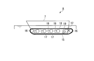
- the traveling unit 5 includes an idler pulley (drive wheel) 16 (or sprocket), a lower roller (driven wheel) 17 (or an upper wheel), and an idler pulley. 16 and an endless crawler belt 18 wound around the lower roller 17 may be provided.
- a plurality of lower rolling wheels 17 are respectively provided on movable support arms 19 that can rotate and / or extend and contract. It may be supported.
- the position (shape) of the crawler belt suitable for water navigation, land travel, and landing can be changed by rotating and / or expanding and contracting these movable support arms 19.
- the amphibious vehicle A can be tilted by selectively rotating and / or expanding and contracting the plurality of movable support arms 19, and the attitude of the amphibious vehicle A can be freely operated.
- the opening 15 of the second cooling source introduction unit 14 is opened and closed by the movable support arm 19 whose position changes during water navigation, landing, and land traveling. It may be configured.
- the movable support arm 19 is movable, so that the opening 15 of the second cooling source introduction unit 14 is fully opened at the time of water navigation, while the second cooling source introduction unit 14 is at the time of landing.
- You may comprise so that the opening part 15 of the 2nd cooling source introduction part 14 may close at the time of land driving
- the movable support arm 19 supports the lower wheel 17 of the plurality of wheels at the first position in the vertical direction and supports the lower wheel 17 at the second position in the vertical direction.
- the second state is displaceable.
- the lower wheel 17 at the second position is above the lower wheel 17 at the first position relative to the vehicle body 7.
- the first state in which the movable support arm 19 supports the lower wheel 17 at the first position is executed, for example, during land travel shown in FIG.
- the second state in which the movable support arm supports the lower wheel 17 at the second position is executed, for example, at the time of water navigation shown in FIG. As shown in FIG.
- the opening 15 of the second cooling source introduction unit 14 is a position that is blocked by the movable support arm 19 when the movable support arm 19 is in the first state, as shown in FIG.
- the movable support arm 19 is disposed at a position not blocked by the movable support arm 19 when the movable support arm 19 is in the second state.
- the movable support arm 19 closes the opening 15 of the second cooling source introduction portion 14, so that the opening 15 of the second cooling source introduction portion 14 can be connected to the side surface or the rear surface of the vehicle body 7. Even when the opening is formed in the opening, it is possible to prevent foreign matters such as earth and sand from entering the inside through the opening 15. Further, since the movable support arm 19 opens the opening 15 of the second cooling source introduction part 14 at the time of water navigation and landing, it is preferable to take in water from the opening 15 of the second cooling source introduction part 14. The engine 1 and the like can be cooled.
- the state in which the opening 15 of the second cooling source introduction unit 14 is closed by the movable support arm 19 in the present embodiment is not only the state in which foreign matter such as earth and sand does not enter the opening 15 by the movable support arm 19.
- the state where it is difficult to enter is also included, and for example, there may be a gap between the movable support arm 19 and the opening 15.
- the power section can be cooled stably.
- Cooling unit 11 Air-cooled cooler 12 Water-cooled cooler 13 First cooling source introduction unit 14 Second cooling source introduction unit 15 Opening (take-in port) of second cooling source introduction unit 16 idler pulley (drive wheel) 17 Downwheel (driven wheel) 18 Track 19 Mobile support arm A Amphibious vehicle
Landscapes
- Engineering & Computer Science (AREA)
- Chemical & Material Sciences (AREA)
- Combustion & Propulsion (AREA)
- Mechanical Engineering (AREA)
- Transportation (AREA)
- Ocean & Marine Engineering (AREA)
- Cooling, Air Intake And Gas Exhaust, And Fuel Tank Arrangements In Propulsion Units (AREA)
- General Details Of Gearings (AREA)
Abstract
車両本体(7)と、車両本体を陸上で走行させるための走行部(5)と、車両本体を水上で航行させるための推進部(6)と、走行部と推進部に動力を付与する動力部(1)と、動力部を冷却するための冷却部(10)とを備える。冷却部は、空気を外部から取り込む第一冷却源導入部(13)と、水を外部から取り込む第二冷却源導入部(14)とを有する。第二冷却源導入部は、水を取り込む開口部(15)を有する。開口部は、車両本体(7)全体の重心(G)よりも後方側で且つ車両本体(7)の外面のうち吃水部で開口している。
Description
本発明は、水陸両用車に関する。
本願は、2015年3月19日に、日本国に出願された特願2015-056031号に基づき優先権を主張し、この内容をここに援用する。
本願は、2015年3月19日に、日本国に出願された特願2015-056031号に基づき優先権を主張し、この内容をここに援用する。
水陸両用車は、例えば、動力源のエンジンと、このエンジンからの駆動力を伝達する動力伝達手段と、陸上走行手段と、水上航行手段とを備えている。動力伝達手段は、エンジンからの駆動力を伝達するプロペラシャフト等である。陸上走行手段は、動力伝達手段を介してエンジンから伝達される駆動力で駆動する車輪や履帯等である。水上航行手段は、陸上走行手段から切り替ってエンジンからの駆動力で駆動するウォータージェット機構やスクリュー等である。
水陸両用車では、水上航行手段としてウォータージェット機構を採用した場合、ウォータージェット機構からのウォータージェットの推進力で水上を高速で航行(滑走)する。また、水上航行手段としてウォータージェット機構を採用した場合、水上から上陸する際に陸上走行手段の駆動に切り替えることにより円滑に地上走行(自走)に移行できる。
特許文献1に開示されている水陸両用車の船体(車両本体)は、第一船底と第二船底を備えた二重底構造である。この水陸両用車では、これら第一船底と第二船底の間の空間部にプロペラシャフトやデファレンシャルギア等のギアボックスが設置されている。空間部は、船体の前面と後面で開口している。
特許文献2に開示されている水陸両用車は、車両本体と、ウォータージェット機構と、水冷式熱交換器と、を備えている。ウォータージェット機構は、ウォータージェット通水路と、羽根車及びシャフトを備えた推進器とを備えている。ウォータージェット通路は、車両本体の底面に形成された取込口と、車両本体の後面に形成された排出口を有する。推進器の羽根車は、ウォータージェット通水路内に設けられている。推進器のシャフトは、エンジンの駆動力を羽根車に伝達する。羽根熊は、エンジンの動力によって駆動し、水上航行時に取込口から水を取り込み、排出口からウォータージェットとして水を排出させる。
特許文献2の水陸両用車は、水冷式熱交換器に水を送る冷却水通路を有する。冷却水通路は、ウォータージェット通水路中で且つ羽根車よりも排出口側で開口する冷却用取込口を有する。この水陸両用車では、水冷式熱交換器で、冷却水通路からの水とエンジン冷却水や作動油などを冷却する。
水陸両用車は、水上を航行すると共に、陸上を走行する。さらに、水陸両用車は、水上から陸上に上陸する場合もある。このように、水陸両用車は、移動形態として各種形態がある。このため、水陸両用車には、各移動形態で動力部が安定して冷却されることが望まれる。
そこで、本発明は、動力部が安定して冷却される水陸両用車を提供することを目的とする。
前記目的を達成するための発明に係る第一形態としての水陸両用車は、
車両本体と、前記車両本体を陸上で走行させるための走行部と、水中で推進力を発生させ、前記車両本体を水上で航行させるための推進部と、前記走行部と前記推進部に動力を付与する動力部と、少なくとも前記動力部を冷却する冷却部とを備え、前記冷却部は、冷却源としての空気を外部から取り込む第一冷却源導入部と、冷却源としての水を外部から取り込む第二冷却源導入部とを有し、前記第二冷却源導入部は、水を取り込む開口部を有し、前記開口部が車両本体全体の重心よりも後方側で、且つ前記車両本体の外面のうち吃水部で開口している。
車両本体と、前記車両本体を陸上で走行させるための走行部と、水中で推進力を発生させ、前記車両本体を水上で航行させるための推進部と、前記走行部と前記推進部に動力を付与する動力部と、少なくとも前記動力部を冷却する冷却部とを備え、前記冷却部は、冷却源としての空気を外部から取り込む第一冷却源導入部と、冷却源としての水を外部から取り込む第二冷却源導入部とを有し、前記第二冷却源導入部は、水を取り込む開口部を有し、前記開口部が車両本体全体の重心よりも後方側で、且つ前記車両本体の外面のうち吃水部で開口している。
当該水陸両用車では、高出力が必要な水上航行時に冷却部の第二冷却源導入部から水を取り込み、この水を冷却源として動力部などを冷却することができる。
当該水陸両用車では、第二冷却源導入部の水を取り込む開口部が車両本体全体の重心よりも後方側に、且つ車両本体の外面のうち吃水部に開口して設けられている。このため、当該水陸両用車では、上陸時、車両本体の前部が上方に、後部が下方に配される傾斜姿勢になった場合でも、開口部を水中に位置させることができ、すなわち、長い間(例えば最後まで)開口部を水中に位置させ水を取り込み続けることができる。よって、当該水陸両用車では、上陸時に前述したように車両本体が傾斜姿勢になっている場合でも、第二冷却源導入部から取り込んだ水を冷却源として効果的に動力部などを冷却することができる。
前記目的を達成するための発明に係る第二形態としての水陸両用車は、
前記第一態様としての水陸両用車において、前記推進部は、ウォータージェットを推進力として発生させるウォータージェット機構であり、前記ウォータージェット機構は、水が流れるウォータージェット通水路と、前記ウォータージェット通水路中に配置され前記動力部からの動力で回転する羽根車と、を有し、前記ウォータージェット通水路は、外部から水を取り込む導入口を有し、前記ウォータージェット通水路の前記導入口と前記第二冷却源導入部の前記開口部とは、前記車両本体の外面のうちで互いに異なる位置に配置され、前記第二冷却源導入部は、前記ウォータージェット通水路に対して独立した通路である。
前記第一態様としての水陸両用車において、前記推進部は、ウォータージェットを推進力として発生させるウォータージェット機構であり、前記ウォータージェット機構は、水が流れるウォータージェット通水路と、前記ウォータージェット通水路中に配置され前記動力部からの動力で回転する羽根車と、を有し、前記ウォータージェット通水路は、外部から水を取り込む導入口を有し、前記ウォータージェット通水路の前記導入口と前記第二冷却源導入部の前記開口部とは、前記車両本体の外面のうちで互いに異なる位置に配置され、前記第二冷却源導入部は、前記ウォータージェット通水路に対して独立した通路である。
水陸両用車では、海上を航行した場合、海水の塩分に起因して腐食が発生するおそれがある。このため、海上を航行した後、陸上で、真水等の洗浄水を用いて、水陸両用車を洗浄する必要がある。当該水陸両用車では、第二冷却源導入部がウォータージェット通水路に対して独立した通路であるため、ウォータージェット通水路内の羽根車に邪魔されずに、第二冷却源導入部内に洗浄液を容易に供給することができる。例えば、第二冷却源導入部の奥まで、洗浄液の噴流を送ることができる。よって、当該水陸両用車では、第二冷却源導入部内を容易に洗浄液で洗浄することができる。
前記目的を達成するための発明に係る第三形態としての水陸両用車は、
前記第一態様又は前記第二態様としての水陸両用車において、前記第二冷却源導入部の前記開口部が前記車両本体の側方視または後方視で露出するように配置されていてもよい。
前記第一態様又は前記第二態様としての水陸両用車において、前記第二冷却源導入部の前記開口部が前記車両本体の側方視または後方視で露出するように配置されていてもよい。
当該水陸両用車では、第二冷却源導入部の開口部が車両本体の底面に配置されている場合よりも、第二冷却源導入部内に容易に洗浄液を供給することができる。
前記目的を達成するための発明に係る第四形態としての水陸両用車は、
前記第一から第三態様のうちのいずれか一態様としての水陸両用車において、前記第二冷却源導入部の開口部が前記車両本体の全長方向の後方1/4の範囲に設けられていてもよい。
前記第一から第三態様のうちのいずれか一態様としての水陸両用車において、前記第二冷却源導入部の開口部が前記車両本体の全長方向の後方1/4の範囲に設けられていてもよい。
前記目的を達成するための発明に係る第五形態としての水陸両用車は、
前記第一から第四態様のうちのいずれか一態様としての水陸両用車において、前記走行部が複数の車輪を有し、前記第二冷却源導入部の開口部が最後方の車輪よりも後方に配置されていてもよい。
前記第一から第四態様のうちのいずれか一態様としての水陸両用車において、前記走行部が複数の車輪を有し、前記第二冷却源導入部の開口部が最後方の車輪よりも後方に配置されていてもよい。
前記目的を達成するための発明に係る第六形態としての水陸両用車は、
前記走行部は、駆動輪及び従動輪を含む複数の車輪と、複数の前記車輪に巻き回された履帯と、複数の前記車輪のうちの少なくとも一部の車輪を上下方向に移動可能に支持する可動支持アームと、を有し、前記可動支持アームは、前記少なくとも一部の車輪を上下方向の第一の位置で支持する第一状態と、前記少なくとも一部の車輪を、前記車両本体に対して相対的に前記第一の位置よりも上側の第二の位置で支持する第二状態とに変位可能であり、前記第二冷却源導入部の前記開口部は、前記可動支持アームが前記第一状態のときに前記可動支持アームにより塞がれる位置であって、前記可動支持アームが前記第二状態のときに前記可動支持アームにより塞がれない位置に配置されていてもよい。
前記走行部は、駆動輪及び従動輪を含む複数の車輪と、複数の前記車輪に巻き回された履帯と、複数の前記車輪のうちの少なくとも一部の車輪を上下方向に移動可能に支持する可動支持アームと、を有し、前記可動支持アームは、前記少なくとも一部の車輪を上下方向の第一の位置で支持する第一状態と、前記少なくとも一部の車輪を、前記車両本体に対して相対的に前記第一の位置よりも上側の第二の位置で支持する第二状態とに変位可能であり、前記第二冷却源導入部の前記開口部は、前記可動支持アームが前記第一状態のときに前記可動支持アームにより塞がれる位置であって、前記可動支持アームが前記第二状態のときに前記可動支持アームにより塞がれない位置に配置されていてもよい。
なお、第六形態としての水陸両用車において、可動支持アームによる第二冷却源導入部の開口部の開閉は、厳密に可動支持アームが開口部を閉塞させなくてもよい。すなわち、第六形態としての水陸両用車における可動支持アームによって第二冷却源導入部の開口部が閉じている状態には、可動支持アームが障害となって開口部に土砂などの異物が入らない状態だけでなく、入りにくくなった状態も含まれる。このため、可動支持アームと開口部の間に隙間があってもよい。
本発明の一態様によれば、動力部を安定して冷却することができる。
図1から図7を参照し、本発明に係る実施形態の水陸両用車について説明する。
本実施形態の水陸両用車は、エンジンにより推進器を駆動させて水上を航行可能であると共に、エンジンにより駆動輪を回転させて陸上を走行可能である。
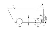
具体的に、本実施形態の水陸両用車Aは、図1及び図2に示すように、車両本体7と、この車両本体7に搭載されている動力伝達駆動系と、を備えている。動力伝達駆動系は、例えば、動力部であるディーゼルエンジン等のエンジン1と、変速機2と、動力分配機構3と、差動装置4と、陸上で走行させるための走行部5と、水中で推進力を発生させ、水上で航行させるための推進部6とを備えている。
車両本体7は、水上航行時に浸水しないように所望の水密性能を備えて構成されている。
変速機2は、手動変速機又は自動変速機である。この変速機2は、エンジン1の出力軸に繋がって一体に回転可能に設けられた入力軸と、動力分配機構3に動力を伝達する出力軸とを有する。変速機2は、入力軸に入力された動力を所望の変速比で変速して出力軸に伝達する。
動力分配機構3は、例えば遊星歯車機構で構成され、入力された回転動力を差動装置4及び(又は)推進部6に分配する。
差動装置4は、動力分配機構3に接続され、動力分配機構3から伝達された動力を車軸を介して走行部5の駆動輪8に伝達する。この差動装置4は、陸上走行する水陸両用車Aの旋回時において旋回内側の駆動輪8と旋回外側の駆動輪8との間に回転差を生じさせ、円滑な旋回走行を可能にする。
本実施形態の走行部5は、動力分配機構3から動力が伝達される車軸と、この車軸に接続されている駆動輪(タイヤ)8とを有する。本実施形態の水陸両用車Aは、陸上走行時、駆動輪8が地面に接地することで自走することができる。
ここで、本実施形態では、走行部5が駆動輪のタイヤを備えたホイール式であるものとしたが、クローラ式(装軌式)であってもよい。なお、このようにクローラ式の走行部5を適用した場合には差動装置4が不要になる。
推進部6は、車両本体7の後部(水陸両用車Aの重心よりも全長方向(長さ方向)後方側の部分、船尾)側に設けられている。
本実施形態の推進部6は、ウォータージェット機構であり、ウォータージェット通水路6aと、ウォータージェット通水路6a内に設けられた羽根車6bと、羽根車6bに連結された推進軸6cとを備えている。推進軸6cは、動力分配機構3に接続されている。羽根車6bは、動力分配機構3からの動力が推進軸を介して伝達され、この伝達された動力によって回転する。
また、ウォータージェット通水路6aは、水を取り込むための導入口6dと、取水した水を噴き出す噴出口6eとを有する。導入口6dは、車両本体7中で水上航行時において水中に没する吃水部に形成されている。噴出口6eは、車両本体7の後面の下方側に形成されている。
本実施形態の推進部6においては、動力分配機構3から推進軸6cに回転動力が伝達されて推進軸6cが軸線周りに回転すると、羽根車6bが旋回する。羽根車6bが旋回すると、導入口6dから水がウォータージェット通水路6aに取り込まれ、この水が羽根車6bで高圧化されてウォータージェット通水路6a内を流通し、噴出口6eから車両本体7の後方に向けウォータージェットとして噴射される。水陸両用車Aは、このように発生したウォータージェットを推進力とし、水上航行することができる。また、水陸両用車Aは、ウォータージェットを推進力とすることで高速航行も可能である。
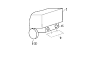
なお、必要に応じて、車両本体7の後部には、噴出口6eから噴出したウォータージェットを推進力として水陸両用車Aが水上航行する際に水陸両用車Aのトリム角を調整するためのフラップ9が取り付けられている。
本実施形態では、水上航行用の推進部6としてウォータージェット機構を用いている。しかしながら、ウォータージェット機構ではなく、例えば推進部としてスクリュープロペラを用い、このスクリュープロペラの回転で発生した水流を推進力としてもよい。すなわち、推進部は、水上航行のための水力を発生するものであれば、如何なるものでもよい。
本実施形態の水陸両用車Aは、さらに、少なくともエンジン1を冷却するための冷却部10を備えている。本実施形態の冷却部10は、空冷式冷却器11と、水冷式冷却器12と、空気を外部から取り込んで空冷式冷却器11に供給する第一冷却源導入部13と、水を外部から取り込んで水冷式冷却器12に供給する第二冷却源導入部14と、を備えている。空冷式冷却器11は、エンジン冷却水、エンジン吸気、作動油などの冷却対象物を、空気を冷媒として用いて冷却する。水冷式冷却器12は、前述の冷却対象物を水(冷却水)を冷媒として用いて冷却する。
本実施形態では、陸上走行時(及び水上航行時、上陸時)に、第一冷却源導入部13から内部に外部の空気を導入し、この空気を空冷式冷却器11に送る。空冷式冷却器11では、この空気を冷媒として利用することでエンジン1を含む冷却対象を冷却する。
ここで、図7に示すように、本実施形態の水陸両用車Aでは、水上を高速航行している際の機関トルクは、陸上走行時の機関トルクより大きくなる。また、水上から陸上へ上陸する際、水陸両用車Aの重心位置が次第に高くなる。しかも、上陸時には、走行部5と共に推進部6も駆動させる必要がある。このため、水陸両用車Aは、水平方向に高速移動していなくても、上陸時の機関トルクは、陸上走行時の機関トルクより大きくなる。
よって、本実施形態の水陸両用車Aでは、水上を高速航行する際や、上陸する際には、エンジン1の出力を高くする必要がある。
そこで、本実施形態では、水上航行時だけでなく上陸時に、第二冷却源導入部14から内部に水を導入し、この水を水冷式冷却器12に送る。水冷式冷却器12は、比熱の大きな水を冷媒として利用することでエンジン1を含む冷却対象を冷却する。
一方、陸上走行時には、水上航行や上陸時と比べてエンジン1の出力が低出力で済むため、冷媒として空気を用いる空冷式熱交換器のみによって冷却対象を十分に冷却することができる。
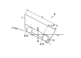
本実施形態の水陸両用車Aでは、図1~図3に示すように、第二冷却源導入部14の水を取り込む開口部(取込口)15が車両本体7全体(水陸両用車A全体)の重心Gよりも後方側に、且つ車両本体7の外面の吃水部で開口している。なお、ここでの吃水部とは、水陸両用車Aが最軽量の状態、つまり水陸両用車Aに搭載されている物がない等の状態での水上航行時に、車両本体7中で水中に没する部分である。
これにより、上陸時に水陸両用車Aが前部を上方に、下部を下方にして傾斜した姿勢になったときにも、第二冷却源導入部14の開口部15が長い間水中に配される。このため、本実施形態の水陸両用車Aでは、この開口部15から水を取り込み、水冷式冷却器12に水を送り続けることで、エンジン1などを比熱の大きな水で冷却し続けることができる。
また、本実施形態の水陸両用車Aにおいては、第二冷却源導入部14の開口部15が車両本体7の全長L方向の後方1/4の範囲に配置されていることが好ましい。ここで、全長L方向の後方1/4の範囲とは、車両本体の最後端から前側へ車両本体の全長Lの1/4の距離の位置までの範囲である。さらに、第二冷却源導入部14の開口部15が最後方の車輪8よりも後方に配置されていることが好ましい。
このように構成すると、上陸時に水陸両用車Aが前部を上方に、下部を下方にして傾斜した姿勢になったとき、より確実に第二冷却源導入部14の開口部15を長い間水中に配して水を取り込み続けることができる。これにより、水陸両用車Aが陸上に上がりきるまで水冷式冷却器12でエンジン1などを冷却し続けることが可能になる。
また、本実施形態の水陸両用車Aにおいては、第二冷却源導入部14の水を取り込む開口部15がウォータージェット用の水を取り込む導入口6dと分離し、それぞれ水中から水を取り込めるように配置されている。すなわち、ウォータージェット通水路6aの導入口6dと第二冷却源導入部14の開口部15とは、車両本体7の外面のうちで互いに異なる位置に配置され、第二冷却源導入部14は、ウォータージェット通水路6aに対して独立した通路である。
水陸両用車Aでは、海上を航行した場合、海水の塩分に起因して腐食が発生するおそれがある。このため、海上を航行した後、陸上で、真水等の洗浄水を用いて、水陸両用車Aを洗浄する必要がある。本実施形態の水陸両用車Aでは、第二冷却源導入部14がウォータージェット通水路6aに対して独立した通路であるため、ウォータージェット通水路6a内の羽根車6bに邪魔されずに、第二冷却源導入部14内に洗浄液を容易に供給することができる。例えば、第二冷却源導入部14の奥まで、洗浄液の噴流を送ることができる。よって、本実施形態の水陸両用車Aでは、第二冷却源導入部内を容易に洗浄液で洗浄することができる。
さらに、本実施形態の水陸両用車Aにおいては、第二冷却源導入部14の開口部15が車両本体7の側方視または後方視で露出するように配設されていることがより好ましい。言い換えれば、第二冷却源導入部14の開口部15が車両本体7の吃水部の側面又は後面に開口形成されていることがより好ましい。また、図4に示すように、トリム角調整用のフラップ9がない場合には、車両本体7の後面に好適に第二冷却源導入部14の開口部15を設けることができる。
このように構成すると、上記の通り、上陸時に第二冷却源導入部14の開口部15から水を取り込んでエンジン1などを冷却し続けることが可能になる。また、水陸両用車Aを前述したように洗浄水で洗浄する場合、第二冷却源導入部14の開口部15が車両本体7の吃水部の側面又は後面に開口形成されていることにより、開口部15から洗浄水を入れ易くなり、第二冷却源導入部14の流路を容易に洗浄することができる。
すなわち、第二冷却源導入部14の開口部15が車両本体7の底部に開口形成されていると、洗浄水を流路に供給することが困難になり、洗浄作業に多大な労力を要することになるが、第二冷却源導入部14の開口部15を車両本体7の吃水部の側面又は後面に開口形成することで洗浄作業を容易にすることができる。
以上、本発明に係る水陸両用車の一実施形態について説明したが、本発明は上記の実施形態に限定されるものではなく、その趣旨を逸脱しない範囲で適宜変更可能である。
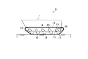
例えば、本実施形態では水陸両用車Aの走行部5が駆動輪8のタイヤを備えたホイール式であるものとして説明を行ったが、前述の通り、本発明に係る水陸両用車Aの走行部5はクローラ式(装軌式)であってもよい。具体的に、走行部5は、図5及び図6に示すように、アイドラプーリ(駆動輪)16(又はスプロケット)と、下転輪(従動輪)17(又は上転輪)と、アイドラプーリ16及び下転輪17に巻き掛けられた無端状の履帯18と、を備えて構成してもよい。
また、このクローラ式の走行部5においては、図5及び図6に示すように、複数の下転輪17(又は上転輪)がそれぞれ回動可能及び/又は伸縮可能な可動支持アーム19に支持されてもよい。この場合、これら可動支持アーム19を回動及び/又は伸縮することによって、水上航行、陸上走行、上陸に適した履帯の位置(形状)を変えることができる。また、陸上では複数の可動支持アーム19を選択的に回動及び/又は伸縮させることによって水陸用両車Aを傾けることができ、水陸両用車Aの姿勢を自在に操作することができる。
このようにクローラ式の走行部5を備える場合には、水上航行時、上陸時、陸上走行時にその位置が変わる可動支持アーム19によって第二冷却源導入部14の開口部15を開閉するように構成してもよい。
例えば、図5及び図6に示すように、可動支持アーム19の可動によって、水上航行時には第二冷却源導入部14の開口部15を全開させるように、上陸時には第二冷却源導入部14の開口部15を全開あるいは半開させるように、陸上走行時には第二冷却源導入部14の開口部15が閉じるように構成してもよい。
具体的に、可動支持アーム19は、複数の車輪のうちの下転輪17を上下方向の第一の位置で支持する第一状態と、下転輪17を上下方向の第二の位置で支持する第二状態とに変位可能である。第二の位置における下転輪17は、車両本体7に対する相対位置が第一の位置における下転輪17よりも上側である。可動支持アーム19が下転輪17を第一の位置で支持している第一状態は、例えば、図5に示す陸上走行時に実行される。また、可動支持アームが下転輪17を第二の位置で支持している第二状態は、例えば、図6に示す水上航行時に実行される。第二冷却源導入部14の開口部15は、図5に示すように、可動支持アーム19が第一状態のときに可動支持アーム19により塞がれる位置であって、図6に示すように、可動支持アーム19が第二状態のときに可動支持アーム19により塞がれない位置に配置されている。
このように、陸上走行時に、可動支持アーム19が第二冷却源導入部14の開口部15を閉じていることにより、第二冷却源導入部14の開口部15を車両本体7の側面や後面に開口形成した場合であっても、土砂などの異物が開口部15から内部に入り込むことを抑えることができる。また、水上航行時及び上陸時に可動支持アーム19が第二冷却源導入部14の開口部15を開いていることにより、この第二冷却源導入部14の開口部15から水を取り込んで好適にエンジン1などを冷却することができる。
なお、本実施形態における可動支持アーム19によって第二冷却源導入部14の開口部15が閉じている状態には、可動支持アーム19によって開口部15に土砂などの異物が入らない状態だけでなく、入りにくくなる状態も含まれ、例えば可動支持アーム19と開口部15の間に隙間があっても構わない。
本発明の一態様によれば、動力部を安定して冷却することができる。
1 エンジン(動力部)
2 変速機
3 動力分配機構
4 差動装置
5 走行部
6 推進部
6a ウォータージェット通水路
6b 羽根車
6c 推進軸
6d 導入口
6e 噴出口
7 車両本体
8 駆動輪(又は単に車輪)
9 フラップ
10 冷却部
11 空冷式冷却器
12 水冷式冷却器
13 第一冷却源導入部
14 第二冷却源導入部
15 第二冷却源導入部の開口部(取込口)
16 アイドラプーリ(駆動輪)
17 下転輪(従動輪)
18 履帯
19 可動支持アーム
A 水陸両用車
2 変速機
3 動力分配機構
4 差動装置
5 走行部
6 推進部
6a ウォータージェット通水路
6b 羽根車
6c 推進軸
6d 導入口
6e 噴出口
7 車両本体
8 駆動輪(又は単に車輪)
9 フラップ
10 冷却部
11 空冷式冷却器
12 水冷式冷却器
13 第一冷却源導入部
14 第二冷却源導入部
15 第二冷却源導入部の開口部(取込口)
16 アイドラプーリ(駆動輪)
17 下転輪(従動輪)
18 履帯
19 可動支持アーム
A 水陸両用車
Claims (6)
- 車両本体と、
前記車両本体を陸上で走行させるための走行部と、
水中で推進力を発生させ、前記車両本体を水上で航行させるための推進部と、
前記走行部と前記推進部に動力を付与する動力部と、
少なくとも前記動力部を冷却する冷却部とを備え、
前記冷却部は、冷却源としての空気を外部から取り込む第一冷却源導入部と、冷却源としての水を外部から取り込む第二冷却源導入部とを有し、
前記第二冷却源導入部は、水を取り込む開口部を有し、前記開口部が車両本体全体の重心よりも後方側で、且つ前記車両本体の外面のうち吃水部で開口している水陸両用車。 - 請求項1記載の水陸両用車において、
前記推進部は、ウォータージェットを推進力として発生させるウォータージェット機構であり、
前記ウォータージェット機構は、水が流れるウォータージェット通水路と、前記ウォータージェット通水路中に配置され前記動力部からの動力で回転する羽根車と、を有し、
前記ウォータージェット通水路は、外部から水を取り込む導入口を有し、
前記ウォータージェット通水路の前記導入口と前記第二冷却源導入部の前記開口部とは、前記車両本体の外面のうちで互いに異なる位置に配置され、前記第二冷却源導入部は、前記ウォータージェット通水路に対して独立した通路である水陸両用車。 - 請求項1または請求項2に記載の水陸両用車において、
前記第二冷却源導入部の前記開口部が前記車両本体の側方視または後方視で露出するように配置されていることを特徴とする水陸両用車。 - 請求項1から請求項3のいずれか一項に記載の水陸両用車において、
前記第二冷却源導入部の開口部が前記車両本体の全長方向の後方1/4の範囲に設けられている水陸両用車。 - 請求項1から請求項4のいずれか一項に記載の水陸両用車において、
前記走行部が複数の車輪を有し、
前記第二冷却源導入部の開口部が最後方の車輪よりも後方に配置されている水陸両用車。 - 請求項1から請求項5のいずれか一項に記載の水陸両用車において、
前記走行部は、駆動輪及び従動輪を含む複数の車輪と、複数の前記車輪に巻き回された履帯と、複数の前記車輪のうちの少なくとも一部の車輪を上下方向に移動可能に支持する可動支持アームと、を有し、
前記可動支持アームは、前記少なくとも一部の車輪を上下方向の第一の位置で支持する第一状態と、前記少なくとも一部の車輪を、前記車両本体に対して相対的に前記第一の位置よりも上側の第二の位置で支持する第二状態とに変位可能であり、
前記第二冷却源導入部の前記開口部は、前記可動支持アームが前記第一状態のときに前記可動支持アームにより塞がれる位置であって、前記可動支持アームが前記第二状態のときに前記可動支持アームにより塞がれない位置に配置されている水陸両用車。
Priority Applications (1)
| Application Number | Priority Date | Filing Date | Title |
|---|---|---|---|
| US15/557,984 US10279639B2 (en) | 2015-03-19 | 2016-01-12 | Amphibious vehicle |
Applications Claiming Priority (2)
| Application Number | Priority Date | Filing Date | Title |
|---|---|---|---|
| JP2015056031A JP6512694B2 (ja) | 2015-03-19 | 2015-03-19 | 水陸両用車 |
| JP2015-056031 | 2015-03-19 |
Publications (1)
| Publication Number | Publication Date |
|---|---|
| WO2016147685A1 true WO2016147685A1 (ja) | 2016-09-22 |
Family
ID=56920308
Family Applications (1)
| Application Number | Title | Priority Date | Filing Date |
|---|---|---|---|
| PCT/JP2016/050646 Ceased WO2016147685A1 (ja) | 2015-03-19 | 2016-01-12 | 水陸両用車 |
Country Status (3)
| Country | Link |
|---|---|
| US (1) | US10279639B2 (ja) |
| JP (1) | JP6512694B2 (ja) |
| WO (1) | WO2016147685A1 (ja) |
Families Citing this family (6)
| Publication number | Priority date | Publication date | Assignee | Title |
|---|---|---|---|---|
| US11247522B2 (en) * | 2016-10-27 | 2022-02-15 | Robotic Research Opco, Llc | Vehicle capable of multiple varieties of locomotion |
| KR20190090214A (ko) * | 2018-01-24 | 2019-08-01 | 한화디펜스 주식회사 | 수륙양용차량의 냉각 장치 |
| CA3142485A1 (en) * | 2019-06-12 | 2020-12-17 | Oceana Energy Company | Systems and methods for deploying hydroelectric energy systems |
| US11340618B2 (en) | 2019-08-08 | 2022-05-24 | Robotic Research Opco, Llc | Drone based inspection system at railroad crossings |
| US11247089B2 (en) | 2019-08-22 | 2022-02-15 | Robotic Research Opco, Llc | Chemical and biological warfare agent decontamination drone |
| CN118622455B (zh) * | 2024-06-27 | 2025-12-02 | 中国北方车辆研究所 | 一种用于两栖装甲车辆的冷却系统 |
Citations (2)
| Publication number | Priority date | Publication date | Assignee | Title |
|---|---|---|---|---|
| JPS474175Y1 (ja) * | 1967-12-05 | 1972-02-14 | ||
| JP2006509138A (ja) * | 2002-05-03 | 2006-03-16 | ギブス テクノロジーズ リミティッド | 水陸両用ビークルの冷却システム |
Family Cites Families (8)
| Publication number | Priority date | Publication date | Assignee | Title |
|---|---|---|---|---|
| AT383999B (de) * | 1985-10-28 | 1987-09-10 | Steyr Daimler Puch Ag | Kuehleinrichtung fuer tauch- bzw. schwimmfaehige kraftfahrzeuge mit fluessigkeitsgekuehltem motor |
| EP0492655A1 (en) * | 1990-12-17 | 1992-07-01 | Isuzu Motors Limited | Amphibian motor vehicle |
| JPH0584598U (ja) * | 1992-04-23 | 1993-11-16 | 日立造船株式会社 | ウォータージェット船の排水管構造 |
| US5690046A (en) * | 1995-11-21 | 1997-11-25 | Grzech, Jr.; Albert S. | Amphibious vehicles |
| GB2420592B (en) * | 2004-11-29 | 2007-04-25 | Gibbs Tech Ltd | An exhaust cooling system of an amphibious vehicle |
| GB2420593B (en) | 2004-11-29 | 2007-04-25 | Gibbs Tech Ltd | An exhaust cooling system of an amphibious vehicle |
| JP2013132995A (ja) | 2011-12-26 | 2013-07-08 | Mitsubishi Heavy Ind Ltd | 水陸両用車 |
| JP5797111B2 (ja) | 2011-12-28 | 2015-10-21 | 三菱重工業株式会社 | 水陸両用車両の冷却構造 |
-
2015
- 2015-03-19 JP JP2015056031A patent/JP6512694B2/ja active Active
-
2016
- 2016-01-12 US US15/557,984 patent/US10279639B2/en active Active
- 2016-01-12 WO PCT/JP2016/050646 patent/WO2016147685A1/ja not_active Ceased
Patent Citations (2)
| Publication number | Priority date | Publication date | Assignee | Title |
|---|---|---|---|---|
| JPS474175Y1 (ja) * | 1967-12-05 | 1972-02-14 | ||
| JP2006509138A (ja) * | 2002-05-03 | 2006-03-16 | ギブス テクノロジーズ リミティッド | 水陸両用ビークルの冷却システム |
Also Published As
| Publication number | Publication date |
|---|---|
| JP6512694B2 (ja) | 2019-05-15 |
| US10279639B2 (en) | 2019-05-07 |
| US20180079268A1 (en) | 2018-03-22 |
| JP2016175483A (ja) | 2016-10-06 |
Similar Documents
| Publication | Publication Date | Title |
|---|---|---|
| US10279639B2 (en) | Amphibious vehicle | |
| US7833071B2 (en) | Amphibious all-terrain vehicle | |
| US3057320A (en) | Boat transom propulsion unit | |
| WO2009033153A3 (en) | High water-speed tracked amphibian | |
| US6808430B1 (en) | Amphibious vehicle | |
| AU2009316221A1 (en) | Lateral thruster for a vessel | |
| US20240262481A1 (en) | Modular, replaceable outboard fairings for application specific optimization | |
| US12296934B2 (en) | Dual strut power transmission housing structure of a marine propulsion system | |
| US1344518A (en) | Propulsion and steering of ships | |
| CN113022243B (zh) | 一种潜航式水陆两栖车 | |
| JP2013132995A (ja) | 水陸両用車 | |
| JP2016175483A5 (ja) | ||
| GB2254831A (en) | Amphibious motor cycle | |
| JP3537547B2 (ja) | 船舶推進機の冷却水通路構造 | |
| JP6061925B2 (ja) | 水陸両用車 | |
| US20240278892A1 (en) | Modular belt tensioning mechanism and powerhead structure of a marine propulsion system | |
| US20240174335A1 (en) | Vessel propelling system and assembly | |
| US7001229B2 (en) | Water vehicle propeller | |
| KR20170079802A (ko) | 추진기 겸용 스러스터를 갖는 선박 | |
| US9738363B1 (en) | Continuous track outboard motor for watercraft propulsion | |
| US20070028824A1 (en) | Boat control system | |
| JP2013252774A (ja) | 船舶 | |
| JP2023094184A (ja) | 船外機 | |
| RU225951U1 (ru) | Устройство компенсации сноса плавающей машины течением воды | |
| US10081417B2 (en) | Marine propulsion system |
Legal Events
| Date | Code | Title | Description |
|---|---|---|---|
| 121 | Ep: the epo has been informed by wipo that ep was designated in this application |
Ref document number: 16764516 Country of ref document: EP Kind code of ref document: A1 |
|
| DPE1 | Request for preliminary examination filed after expiration of 19th month from priority date (pct application filed from 20040101) | ||
| WWE | Wipo information: entry into national phase |
Ref document number: 15557984 Country of ref document: US |
|
| NENP | Non-entry into the national phase |
Ref country code: DE |
|
| 122 | Ep: pct application non-entry in european phase |
Ref document number: 16764516 Country of ref document: EP Kind code of ref document: A1 |