WO2016147684A1 - エアバッグ装置 - Google Patents
エアバッグ装置 Download PDFInfo
- Publication number
- WO2016147684A1 WO2016147684A1 PCT/JP2016/050488 JP2016050488W WO2016147684A1 WO 2016147684 A1 WO2016147684 A1 WO 2016147684A1 JP 2016050488 W JP2016050488 W JP 2016050488W WO 2016147684 A1 WO2016147684 A1 WO 2016147684A1
- Authority
- WO
- WIPO (PCT)
- Prior art keywords
- bag
- vehicle
- occupant
- center
- main bag
- Prior art date
- Legal status (The legal status is an assumption and is not a legal conclusion. Google has not performed a legal analysis and makes no representation as to the accuracy of the status listed.)
- Ceased
Links
Images


Classifications
-
- B—PERFORMING OPERATIONS; TRANSPORTING
- B60—VEHICLES IN GENERAL
- B60R—VEHICLES, VEHICLE FITTINGS, OR VEHICLE PARTS, NOT OTHERWISE PROVIDED FOR
- B60R21/00—Arrangements or fittings on vehicles for protecting or preventing injuries to occupants or pedestrians in case of accidents or other traffic risks
- B60R21/02—Occupant safety arrangements or fittings, e.g. crash pads
- B60R21/16—Inflatable occupant restraints or confinements designed to inflate upon impact or impending impact, e.g. air bags
- B60R21/23—Inflatable members
- B60R21/231—Inflatable members characterised by their shape, construction or spatial configuration
-
- B—PERFORMING OPERATIONS; TRANSPORTING
- B60—VEHICLES IN GENERAL
- B60R—VEHICLES, VEHICLE FITTINGS, OR VEHICLE PARTS, NOT OTHERWISE PROVIDED FOR
- B60R21/00—Arrangements or fittings on vehicles for protecting or preventing injuries to occupants or pedestrians in case of accidents or other traffic risks
- B60R21/02—Occupant safety arrangements or fittings, e.g. crash pads
- B60R21/16—Inflatable occupant restraints or confinements designed to inflate upon impact or impending impact, e.g. air bags
- B60R21/20—Arrangements for storing inflatable members in their non-use or deflated condition; Arrangement or mounting of air bag modules or components
- B60R21/205—Arrangements for storing inflatable members in their non-use or deflated condition; Arrangement or mounting of air bag modules or components in dashboards
-
- B—PERFORMING OPERATIONS; TRANSPORTING
- B60—VEHICLES IN GENERAL
- B60R—VEHICLES, VEHICLE FITTINGS, OR VEHICLE PARTS, NOT OTHERWISE PROVIDED FOR
- B60R21/00—Arrangements or fittings on vehicles for protecting or preventing injuries to occupants or pedestrians in case of accidents or other traffic risks
- B60R21/02—Occupant safety arrangements or fittings, e.g. crash pads
- B60R21/16—Inflatable occupant restraints or confinements designed to inflate upon impact or impending impact, e.g. air bags
- B60R21/23—Inflatable members
- B60R21/231—Inflatable members characterised by their shape, construction or spatial configuration
- B60R21/2334—Expansion control features
- B60R21/2338—Tethers
-
- B—PERFORMING OPERATIONS; TRANSPORTING
- B60—VEHICLES IN GENERAL
- B60R—VEHICLES, VEHICLE FITTINGS, OR VEHICLE PARTS, NOT OTHERWISE PROVIDED FOR
- B60R21/00—Arrangements or fittings on vehicles for protecting or preventing injuries to occupants or pedestrians in case of accidents or other traffic risks
- B60R2021/0002—Type of accident
- B60R2021/0009—Oblique collision
-
- B—PERFORMING OPERATIONS; TRANSPORTING
- B60—VEHICLES IN GENERAL
- B60R—VEHICLES, VEHICLE FITTINGS, OR VEHICLE PARTS, NOT OTHERWISE PROVIDED FOR
- B60R21/00—Arrangements or fittings on vehicles for protecting or preventing injuries to occupants or pedestrians in case of accidents or other traffic risks
- B60R21/02—Occupant safety arrangements or fittings, e.g. crash pads
- B60R21/16—Inflatable occupant restraints or confinements designed to inflate upon impact or impending impact, e.g. air bags
- B60R21/23—Inflatable members
- B60R21/231—Inflatable members characterised by their shape, construction or spatial configuration
- B60R2021/23107—Inflatable members characterised by their shape, construction or spatial configuration the bag being integrated in a multi-bag system
-
- B—PERFORMING OPERATIONS; TRANSPORTING
- B60—VEHICLES IN GENERAL
- B60R—VEHICLES, VEHICLE FITTINGS, OR VEHICLE PARTS, NOT OTHERWISE PROVIDED FOR
- B60R21/00—Arrangements or fittings on vehicles for protecting or preventing injuries to occupants or pedestrians in case of accidents or other traffic risks
- B60R21/02—Occupant safety arrangements or fittings, e.g. crash pads
- B60R21/16—Inflatable occupant restraints or confinements designed to inflate upon impact or impending impact, e.g. air bags
- B60R21/23—Inflatable members
- B60R21/231—Inflatable members characterised by their shape, construction or spatial configuration
- B60R2021/23161—Inflatable members characterised by their shape, construction or spatial configuration specially adapted for protecting at least two passengers, e.g. preventing them from hitting each other
-
- B—PERFORMING OPERATIONS; TRANSPORTING
- B60—VEHICLES IN GENERAL
- B60R—VEHICLES, VEHICLE FITTINGS, OR VEHICLE PARTS, NOT OTHERWISE PROVIDED FOR
- B60R21/00—Arrangements or fittings on vehicles for protecting or preventing injuries to occupants or pedestrians in case of accidents or other traffic risks
- B60R21/02—Occupant safety arrangements or fittings, e.g. crash pads
- B60R21/16—Inflatable occupant restraints or confinements designed to inflate upon impact or impending impact, e.g. air bags
- B60R21/23—Inflatable members
- B60R21/231—Inflatable members characterised by their shape, construction or spatial configuration
- B60R21/2334—Expansion control features
- B60R21/2338—Tethers
- B60R2021/23386—External tether means
Definitions
- the present invention relates to an airbag device that restrains a vehicle occupant from the front of the vehicle.
- the airbag device is a safety device that operates in an emergency such as a vehicle collision, and inflates and deploys with gas pressure to receive and protect an occupant.
- airbag devices There are various types of airbag devices depending on the installation location and application.
- a front airbag is installed in the center of the steering wheel in the driver's seat to protect the front seat occupant mainly from front and rear impacts, and an instrument panel and other parts are installed near the passenger seat.
- a passenger airbag is provided.
- a curtain airbag that inflates and deploys along the side window is provided near the ceiling of the wall to protect each occupant in the front and rear rows from side collision and subsequent rollover (rollover).
- the part is provided with a side airbag that is inflated and deployed right next to the passenger.
- the airbag disclosed in Patent Document 1 is mainly for a passenger seat, and has a mechanism for restraining an occupant between two bag-shaped parts. Specifically, a flat left half airbag 12 and a right half airbag 14 are provided, and the space between them is positioned in front of the seat. The left half airbag 12 and the right half airbag 14 are connected by a tie panel 16 at the rear of the vehicle and do not separate more than necessary. With these configurations, the airbag disclosed in Patent Document 1 accepts an occupant appropriately entering the front space.
- the airbag apparatus is also required to cope with irregular collisions and impacts such as so-called oblique collision in which an impact is applied to the vehicle from an oblique front-rear direction.
- An occupant in an oblique collision enters the airbag cushion (hereinafter referred to as “cushion”) in front of the seat with an irregular behavior such as an oblique direction. Therefore, for example, in the configuration of Patent Document 1, since the space for receiving the occupant is located in front of the seat, it is difficult to efficiently restrain the occupant during an oblique collision. In order to exert a sufficient restraining force at the time of an oblique collision, it is required to provide a cushion having a corresponding shape and structure and to keep the cushion in a suitable posture.
- the present invention has been made in view of such a problem, and an object of the present invention is to provide an airbag device that can restrain an occupant in a stable posture and suppress an injury value to the occupant even in an oblique collision.
- a representative configuration of an airbag apparatus is an airbag apparatus that restrains a vehicle occupant, and the airbag apparatus is inflated and deployed in front of the front seat of the vehicle.
- a main bag that is inflated and deployed on the inner side in the vehicle width direction of the main bag, and an upper portion of the valley between the main bag and the center bag, and the center bag is joined to the main bag over a predetermined range in the vehicle front-rear direction. And an upper joining means.
- the center bag can be prevented from moving toward the vehicle interior with respect to the main bag, and the narrowness of the valley can be maintained. Therefore, the center bag can exert a high restraining force to restrain the occupant's head more efficiently and suppress the injury value.
- the above upper joining means is provided over a predetermined range in the vehicle longitudinal direction.
- the head of the occupant may move in the vehicle front-rear direction.
- the upper joint means provided in the vehicle front-rear direction is preferable because the resistance is low even if the head touches.
- the airbag device may restrain the head of the passenger on the rear side of the vehicle in the valley.
- the airbag device can efficiently restrain the occupant's head and suppress the obstacle value.
- the center bag may be inflated and projected from the main bag so as to protrude rearward of the vehicle.
- the passenger in the passenger seat may move diagonally forward inside the vehicle.
- the head when the occupant's head contacts a conventional main bag in front of the passenger seat, the head may rotate clockwise around the neck as viewed from above. Therefore, for example, in the above configuration, the center bag provided inside the main bag is protruded rearward of the main bag.
- the head of the occupant moving obliquely forward on the vehicle interior contacts the center bag mainly from the side of the head at the same time as, or just before or after, the front main bag.
- the clockwise rotation of the head of the occupant can be reduced or canceled.
- the angular velocity of the rotation of the occupant's head can be reduced, the occupant injury value associated with the rotation can be suppressed.
- the above upper joining means may be sewn. With this configuration, the center bag can be suitably joined to the main bag over a predetermined range in the vehicle front-rear direction.
- the upper joint means includes a cloth-like tether that is long in the vehicle front-rear direction, a first joint that joins the first long side of the outer side of the tether to the main bag, and a second long side of the inner side of the tether. And a second joint portion that joins the center bag to the center bag. Also with this configuration, the center bag can be suitably joined to the main bag over a predetermined range in the vehicle front-rear direction.
- the second long side may extend to the rear of the vehicle relative to the first long side, and the second joint may extend to the upper rear end of the center bag.
- the airbag device may further include a lower joining unit that is provided in a lower part of the valley and joins the vehicle rear side of the main bag and the center bag over a predetermined range.
- the valley may be provided at a location where the occupant's head can come into contact, and the lower part of the valley is joined to the main bag and the center bag by the lower joining means, for example, suitably restraining the occupant's chest, etc. It becomes possible.
- the lower joint means may be sewn. With this configuration, it is possible to suitably join the lower portions of the center bag and the main bag.
- the main bag may contact the windshield of the vehicle and the upper surface of the instrument panel of the vehicle by inflating and deploying. That is, the main bag may be inflated and deployed between the windshield and the instrument panel. According to this configuration, the posture of the main bag can be stabilized even when the occupant enters, and the posture of the center bag joined to the main bag by the upper joining means is further stabilized.
- the airbag device further includes a housing that is box-shaped and houses the main bag and the center bag and is provided inside the upper surface portion of the instrument panel of the vehicle.
- the main bag and the center bag are provided on the upper surface of the instrument panel.
- the part may be cleaved and expanded.
- an airbag apparatus that can restrain an occupant in a stable posture and suppress an injury value to the occupant even in an oblique collision.
- FIG.6 It is a schematic diagram in the arrow A of the cushion of FIG.6 (b). It is the figure which illustrated the modification of the upper side joining means illustrated to Fig.3 (a) etc. FIG. It is the figure which illustrated the case where a crew member was restrained with the cushion of Drawing 8 (b).
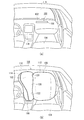
- FIG. 1 is a diagram illustrating an outline of an airbag apparatus 100 according to an embodiment of the present invention.
- FIG. 1A is a diagram illustrating a vehicle before the airbag apparatus 100 is operated.
- the airbag device 100 is embodied for a front seat in a left-hand drive vehicle, particularly for a passenger seat (front row right seat).
- the airbag device 100 is installed inside the upper surface portion 106 on the passenger seat 104 side of the instrument panel 102.
- FIG. 1B is a diagram illustrating the vehicle after the airbag apparatus 100 is operated.
- the cushion 108 of the airbag device 100 restrains the passenger 132 (see FIG. 4A) of the passenger seat 104 from the front of the vehicle.
- the cushion 108 has a bag shape and receives gas from the inflator 110 (see FIG. 4A) to expand and deploy.
- the cushion 108 is formed by overlapping or sewing a plurality of base fabrics constituting the surface, spinning using OPW (One-Piece Woven), or the like.
- OPW One-Piece Woven
- the cushion 108 of the airbag device 100 includes two parts, a main bag 112 and a center bag 114.
- the main bag 112 is a large-capacity part that inflates and deploys to the front side of the passenger seat 104.
- the main bag 112 is inflated and deployed so as to fill a space between the passenger 132 of the passenger seat 104, the instrument panel 102 and the windshield 116. This prevents the passenger 132 from colliding with the instrument panel 102. Further, by preventing the occupant 132 from colliding with the windshield 116, the occupant 132 is also prevented from being released from the vehicle.
- the center bag 114 is a flat part that is inflated and deployed inside the main bag 112 and has a smaller capacity than the main bag 112.
- the center bag 114 is inflated and deployed in front of the center console 118 when viewed from the occupant 132 (see FIG. 5A), so that the occupant 132 moves inside the vehicle or collides with the center console 118 during an oblique collision or the like. prevent.
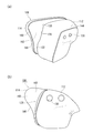
- FIG. 2 and 3 are views illustrating the cushion 108 in FIG. 1B when inflated and deployed from each direction.
- FIG. 2A is a perspective view illustrating a state in which the cushion 108 of FIG. 1B is viewed from above the vehicle outer side.
- a valley 128 is formed between the center bag 114 and the main bag 112. The valley 128 separates the center bag 114 and the main bag 112 on the vehicle rear side. The valley 128 restrains particularly the head E1 of the occupant 132 (see FIG. 5A).
- the center bag 114 and the main bag 112 are connected by, for example, an internal vent hole or the like in front of the valley 128.
- the center bag 114 and the main bag 112 can be provided as independent bags.
- vent holes 130 are provided on the side surface of the main bag 112 outside the vehicle.
- the vent hole 130 is a so-called exhaust hole and discharges the gas supplied from the inflator 110 (see FIG. 4A) to the outside. Since only the side window or the like exists on the outside of the main bag 112 and there is no occupant 132 (see FIG. 4A), it is not possible to provide the vent hole 130 on the side of the main bag 112 on the outside of the vehicle. It is valid.
- FIG. 2B is a diagram illustrating a state in which the cushion 108 of FIG. 2A is viewed from the outside of the vehicle.
- the center bag 114 in the present embodiment has a rear region 160 on the vehicle rear side inflated so as to protrude rearward of the main bag 112 (leftward in FIG. 2B). expand. Accordingly, the outer side surface of the center bag 114 is exposed from the valley 128.
- the center bag 114 mainly restrains the temporal portion E1a of the occupant 132 (see FIG. 4A) at the side surface portion 162 inside the vehicle. Since the center bag 114 is joined to the main bag 112 by the upper joining means 120 and the like described later, the center bag 114 can function as a reaction force surface that restrains the side head E1a.
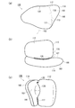
- FIG. 3A is a diagram illustrating a state in which the cushion 108 of FIG. 2B is viewed from the inside of the vehicle.
- the main bag 112 hidden by the center bag 114 is illustrated by a broken line.
- the upper bonding means 120 is provided in the upper part of the valley 128.
- the upper joining means 120 joins the center bag 114 and the main bag 112, and is realized by sewing in the present embodiment.
- the center bag 114 has a flat shape and inflates and expands from above the instrument panel 102 to the rear thereof. However, since the center bag 114 is joined to the main bag 112 by the upper joining means 120, the center bag 114 has a stable posture without moving to the inside of the vehicle. Can keep.
- FIG. 3B is a diagram illustrating a state in which the cushion 108 in FIG. 3A is viewed from above the vehicle.
- the upper joining means 120 is provided by sewing the center bag 114 and the main bag 112 over a predetermined range in the vehicle front-rear direction. Even if a valley 128 is formed between the center bag 114 and the main bag 112, the upper joining means 120 can restrain the passenger 132 (see FIG. 4A) without leaving the main bag 112. It has become.
- the range in which the upper joining means 120 is provided can be set as appropriate. For example, if the center bag 114 and the main bag 112 are connected to each other on the front side of the vehicle, the upper joining means 120 functions sufficiently by being provided at the upper part of the unconnected range (that is, the range of the valley 128). can do. Further, the upper joining means 120 is configured so that the center bag 114 and the main bag 112 are all independent from each other, or even if they are partially connected, the entire vehicle longitudinal direction of the upper part of the main bag 112 is not limited. It is also possible to provide over a range. In any case, the upper joining means 120 can widely improve the occupant restraining force of the main bag 112 over a predetermined range in the vehicle front-rear direction.
- a lower bonding means 122 is provided below the valley 128, a lower bonding means 122 is provided.
- the lower joining means 122 also joins the main bag 112 and the center bag 114 by sewing.
- the lower joining means 122 is mainly provided over a predetermined range in the vertical direction along the rear edge 113 of the main bag 112. By providing the lower joining means 122, the center bag 114 can maintain its posture without falling down to the vehicle interior side.
- the lower joining means 122 and the upper joining means 120 can be realized not only by sewing but also by adhesion or heat welding.
- FIG. 3C is a diagram illustrating a state where the cushion 108 of FIG. 3B is viewed from the rear of the vehicle.
- force is applied to the center bag 114 and the main bag 112 from the inside of the valley 128 in the vehicle width direction to open the valley 128.
- the valley 128 is a part that functions mainly when restraining the head E1 of the occupant 132 (see FIG. 4A).
- the upper joining means 120 and the lower joining means 122 also function suitably, and thereby the center bag 114 is supported so as not to move to the inside of the vehicle even when the occupant 132 comes into contact. Therefore, the center bag 114 can efficiently apply a reaction force from the side surface portion 162 to the occupant 132.
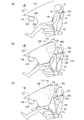
- FIG. 4 is a diagram illustrating a process in which the cushion 108 in FIG. 1B restrains the occupant 132.
- the left side in the figure is the front of the vehicle.
- FIG. 4A is a diagram illustrating an undeployed state of the cushion 108.
- the cushion 108 includes a main bag 112 (see FIG. 4B and the like) and a center bag 114, and is accommodated in the housing 134 in a folded state.
- the housing 134 has, for example, a box shape with an opening at the top, accommodates the folded cushion 108, and is installed inside the upper surface portion 106 of the instrument panel 102.
- the inflator 110 is fixed to the bottom surface of the housing 134.
- the inflator 110 is a gas generator, and is connected to the main bag 112 to supply gas.
- a disk-shaped disk type can be used, but a cylindrical cylinder type may be used.
- Inflators that are currently popular include a type that is filled with a gas generating agent and burns it to generate gas, a type that is filled with compressed gas and supplies gas without generating heat, or There is a hybrid type using both combustion gas and compressed gas. Any type of inflator 110 can be used.
- the inflator 110 operates in response to an impact detection signal from a sensor (not shown) and supplies gas to the main bag 112.
- the main bag 112 and the center bag 114 are connected to each other, and the gas supplied from the inflator 110 to the main bag 112 is also supplied to the center bag 114.
- FIG. 4B is a diagram illustrating the cushion 108 inflated and deployed.
- the cushion 108 is inflated and deployed to the rear of the vehicle by cleaving the upper surface portion 106 of the instrument panel 102 serving as a lid of the housing 134.
- the occupant 132 illustrated in FIG. 4B has entered the cushion 108 side more than the occupant 132 of FIG.
- the occupant 132 moves forward of the vehicle due to inertia.
- the occupant 132 moves in a trajectory that causes the upper body to bend forward about the waist E5.
- the main bag 112 mainly restrains the head E1, the shoulder E3, the chest E4, and the like of the occupant 132.
- the inflated and deployed main bag 112 is in contact with the windshield 116 and the upper surface portion 106 of the instrument panel 102.
- the occupant 132 can be restrained in a stable posture even when the occupant 132 enters.
- the center bag 114 protrudes behind the main bag 112 (right side in FIG. 4B).
- the occupant 132 may move diagonally forward inside the vehicle, particularly with the left shoulder E3a not restrained by the seat belt 136 in front. In that case, the occupant 132 contacts the center bag 114 from the side E1a.
- FIG. 4C is a diagram illustrating a state where the occupant 132 of FIG. 4B has further entered the cushion 108 side.
- the head E ⁇ b> 1 of the occupant 132 is guided into the valley 128 while the side head E ⁇ b> 1 a is in contact with the center bag 114, and is restrained by the valley 128.
- the left shoulder E3a inside the vehicle of the occupant 132 is restrained by the rear end 166 of the rear region 160 of the center bag 114.
- the rear end 166 is inclined so as to gradually protrude rearward as it goes upward.
- the rear end portion 166 of the rear region 160 restrains the left shoulder E3a from the front of the vehicle and supports the upper body of the occupant 132 together with the main bag 112. Thereby, the twist of the upper body of the occupant 132 is offset.
- the upper joint means 120 and the lower joint means 122 also function suitably.
- the upper joining means 120 and the lower joining means 122 join the center bag 114 to the main bag 112. Therefore, even when the occupant 132 enters obliquely forward at the time of an oblique collision or the like, the center bag 114 does not move to the inside of the vehicle, and the side head E1a and the left shoulder E3a are moved with a stable posture and high restraining force. Can be restrained.
- FIG. 5 is a diagram illustrating a state in which the process of restraining the occupant 132 by the cushion 108 of FIG. 4 is viewed from above.
- FIGS. 5A to 5C corresponds to each of FIGS. 4A to 4C.
- the process in which the cushion 108 restrains the occupant 132 will be described with reference to FIGS. 5 (a) to 5 (c).
- FIG. 5A it is assumed that an occupant 132 of the passenger seat 104 is seated while wearing a seat belt 136.
- an operation signal is transmitted from a sensor (not shown) to the airbag device 100, and the cushion 108 is inflated and deployed as shown in FIG. 5B.
- the occupant 132 moves obliquely forward on the inside of the vehicle.
- the center bag 114 projects rearward from the main bag 112, and the head E1 of the occupant 132 contacts the side surface 162 of the center bag 114 on the vehicle exterior side from the side head E1a.
- FIG. 5C is a view in which the occupant 132 of FIG. 5B further enters the cushion 108 side.
- the head E1 of the occupant 132 that moves diagonally forward contacts the main bag 112 that is present in front of the passenger seat 104 the head E1 has a rotational force (arrow) clockwise around the neck E2 as viewed from above.
- the rotation 140) illustrated in FIG. Therefore, in the present embodiment, the rear region 160 of the center bag 114 provided on the inner side of the main bag 112 is extended to the rear of the vehicle from the main bag 112.
- a valley 128 is provided between the main bag 112 and the center bag 114.
- the head E1 of the occupant 132 moving diagonally forward in the vehicle is restrained so as to enter the valley 128 while the side head E1a is in contact with the center bag 114.
- the center bag 114 is joined to the main bag 112 by the upper joining means 120 and the lower joining means 122. Therefore, the center bag 114 can restrain the head E1 without breaking the posture, and can reduce or cancel the rotation 140 generated in the head E1 more efficiently.
- the angular velocity of the rotation 140 of the head E1 of the occupant 132 can be reduced, and the injury value of the head E1 accompanying the rotation 140 can be suppressed.
- the upper joining means 120 is provided to extend in a predetermined range in the vehicle front-rear direction.
- the upper joining means 120 is located above the head E1 of the occupant 132 and may touch the head E1 of the occupant 132 that moves in the vehicle front-rear direction when the occupant is restrained.
- the upper joining means 120 extends forward of the vehicle from the range in which the head E1 can enter the valley 128, and does not contact the head E1 from the front in the moving direction. Less resistance.
- the occupant 132 may move toward the rear of the vehicle after being restrained by the cushion 108.
- the upper joint means 120 is provided in the front-rear direction of the vehicle, the head E1 in contact with the occupant 132 may be moved rearward.
- the upper joining means 120 is provided in the upper part of the cushion 108, the upper surface part 106 (FIG. 5 (a)) and the windshield 116 (FIG. c) etc.) There is a case of touching nearby interior parts. Even in this case, the upper joining means 120 that is long in the vehicle front-rear direction is preferable because there is little room for another part to enter the lower side.
- the rear region 160 of the center bag 114 restrains the left shoulder E3a of the passenger 132 at the rear end 166.
- the occupant 132 is restrained by the seat belt 136 from the right shoulder E3b outside the vehicle to the flank inside the vehicle, but the left shoulder E3a is not restrained by the seat belt 136. Therefore, in an oblique collision, the occupant may head toward the front of the vehicle with the left shoulder E3a set in front of the vehicle.
- the rear end 166 of the center bag 114 restrains the left shoulder E3a from the front and the upper side, and then restrains the right shoulder E3b by the main bag 112.
- the center bag 114 since the center bag 114 is joined to the main bag 112 by the upper joining means 120 and the lower joining means 122, the center bag 114 can also restrain the left shoulder E3a.
- the center bag 114 supported by the upper joining means 120 and the lower joining means 122 is used to restrain the temporal portion E1a to reduce the angular velocity of the rotation 140 of the head portion E1. be able to.
- the left shoulder E3a can be positively constrained to cancel the rotation that occurs in the upper body.
- the center bag 114 maintains the narrowness of the valley 128 without leaving the main bag 112 so far even if the head E1 of the heavy occupant 132 contacts from the outside of the vehicle.
- the part E1 can be restrained. Therefore, the injury value of the passenger 132 can be efficiently suppressed.
- the main bag 112 is inflated so as to be sandwiched between the instrument panel 102 and the windshield 116, and the posture is stable. Since the center bag 114 is joined to the main bag 112 by the upper joining means 120 and the lower joining means 122, the center bag 114 is prevented from being separated from the main bag 112, and the posture is more stable.
- the contact between the occupant 132 and the cushion 108 starts when the temporal region E1a contacts the center bag 114.
- contact between the occupant 132 and the cushion 108 is various, for example, the head E1 contacts the center bag 114 and the main bag 112 simultaneously, or the head E1 contacts the main bag 112 first.
- the head E1 may contact the main bag 112 or the like after the shoulder E3 (see FIG. 4B or the like) or the chest E4 has contacted the main bag 112 or the like.
- the head E1 of the occupant 132 can be guided into the valley 128 and effectively restrained.
- FIG. 5B illustrates a clockwise rotation 140 as an example of the rotation that occurs in the head E1.
- the head E1 may rotate counterclockwise around the neck as viewed from above.
- the valley 128 can be used to reduce or cancel the counterclockwise rotation, and the angular velocity of the head E1 can be reduced. That is, the airbag device 100 of the present embodiment can obtain the same effect with respect to both clockwise and counterclockwise rotations that occur in the head E1.
- FIG. 6 is a diagram illustrating a state in which the process of restraining the occupant 132 by the cushion 108 of FIG. 4 is viewed from the front of the vehicle.
- FIG. 6A it is assumed that the passenger 132 of the passenger seat 104 is seated while wearing the seat belt 136.
- the main bag 112 is inflated and deployed in front of the occupant 132 as shown in FIG. 6B, and the center bag 114 is located on the inner side of the occupant 132 (right side in FIG. 6B). It expands and expands forward.
- the occupant 132 that has moved obliquely forward from the seating position to the inside of the vehicle brings the side head portion E1a into contact with the side surface portion 162 of the center bag 114.
- the left shoulder E3a that is not restrained by the seat belt 136 is restrained by the rear end portion 166 (see FIG. 4B) of the rear region 160 of the center bag 114.
- the head E ⁇ b> 1 enters the valley 128 toward the front of the vehicle while being guided by the center bag 114, and is restrained by the valley 128.
- the center bag 114 can restrain the head E1 of the occupant 132 without moving to the vehicle interior side. .
- FIG. 7 is a schematic diagram of the cushion 108 in FIG.
- the upper body of the occupant 132 moves so as to rotate mainly around the waist E5 when the vehicle is impacted.
- the head E1 of the occupant 132 draws a locus 156 that moves downward from the seating position in addition to moving forward from the vehicle.
- the positions where the upper joining means 120 and the lower joining means 122 are provided are considered.
- the upper joining means 120 and the lower joining means 122 join the center bag 114 and the main bag 112 to form the edge of the valley 128.
- the valley 128 is provided at a position where the head E1 of the occupant 132 can come into contact.
- the upper joining means 120 and the lower joining means 122 are provided at positions where the head E1 of the occupant 132 does not contact.
- the upper joining means 120 is provided above the position where the head E1 of the occupant 132 contacts.
- the lower joining means 122 is provided below the position where the head E1 of the occupant 132 comes into contact and the locus 156 that can occur in the head E1, and the position where the shoulder E3 and the chest E4 come into contact.
- the lower joining means 122 is provided so as to extend substantially vertically along the rear edge 113 of the main bag 112. Accordingly, as described above, the lower portion of the main bag 112 and the center bag 114 can be integrated at the lower portion of the valley 128 to restrain the shoulder portion E3, the chest portion E4, and the like of the occupant 132.
- the direction in which the lower bonding means 122 is provided is not limited to this.
- the lower joining means 122 may be provided so as to easily receive the shoulder portion E3, the chest portion E4, and the like of the occupant 132, and may be provided, for example, inclined so as to gradually move forward and toward the front of the vehicle.
- the cushion 108 can suitably restrain the head E1 of the occupant 132, particularly the side head E1a, by the center bag 114.
- the center bag 114 since the center bag 114 is supported by the upper joining means 120 and the lower joining means 122, the center bag 114 can be restrained even to the rear side of the center of gravity of the head E1 with a stable posture and high restraining force.
- the left shoulder E3a of the occupant 132 is restrained from the front and the upper side below the rear end 166 of the center bag 114, which is in the vicinity of the lower joining means 122. According to these configurations, it is possible to suppress the rotation 140 and upper body rotation that may occur in the head E1 of the occupant 132, and to significantly reduce the injury value of the occupant 132.
- FIG. 8 is a diagram illustrating a modification of the upper joining means 120 illustrated in FIG.
- the upper bonding means 200 illustrated in FIG. 8A is different from the upper bonding means 120 in FIG. 3A in that it includes a tether 202.
- the tether 202 is a cloth-like member that is long in the vehicle front-rear direction, and is formed of the same type of base fabric as the cushion 108, for example.
- the tether 202 is sewn to the upper part of the center bag 114 and the main bag 112 in the vehicle front-rear direction, and these are tied together.
- FIG. 8B is a diagram illustrating a state in which the cushion 108 in FIG. 8A is viewed from above the vehicle.
- the tether 202 is long in the vehicle front-rear direction (left-right direction in FIG. 8B) and has long sides on both sides in the vehicle width direction (up-down direction in FIG. 8B). is doing.
- the first long side 204 on the vehicle inner side (upper side in FIG. 8B) is joined to the upper portion 144 of the main bag 112 by the first joining portion 206.
- the second long side 208 on the outside of the vehicle is joined to the upper part 142 of the center bag 114 by the second joining part 210.
- the first joint portion 206 and the second joint portion 210 are realized by sewing, but can also be realized by bonding or heat welding.
- the second long side 208 extends to the rear of the vehicle (left side in the figure) than the first long side 204.
- the second joint portion 210 is provided with the second long side 208 extending to the upper rear end 178 of the center bag 114.
- FIG. 8C is a diagram illustrating a state in which the cushion 108 of FIG. 8B is viewed from the rear of the vehicle.
- the valley 128 is opened by applying a force in the vehicle width direction to the center bag 114 and the main bag 112 from the inside of the valley 128.
- the upper joint means 200 supports the center bag 114 so that it does not move to the inside of the vehicle. Thereby, the reaction force from the side surface portion 162 can be efficiently applied to the occupant 132.
- FIG. 9 is a diagram illustrating a case where the occupant 132 is restrained by the cushion 108 of FIG. 8B.
- FIG. 9 corresponds to FIG.
- the center bag 114 is less likely to collapse.
- the tether 202 is joined to the upper rear end 178 of the center bag 114. Therefore, the center bag 114 has a stable posture up to the upper rear end 178, and can exhibit a high restraining force over the entire vehicle longitudinal direction.
- the center bag 114 can be restrained even in a range extending from the side head E1a to the back head E1b of the occupant 132.
- the upper joint means 200 can also prevent the center bag 114 from moving when the occupant 132 comes into contact with the center bag 114 and maintain the narrowness of the valley 128. Therefore, the cushion 108 provided with the upper joining means 200 can also efficiently restrain the passenger 132 and suppress the injury value at the time of an oblique collision or the like.
- the tether 202 has a length that extends to the front of the vehicle from the range in which the head E1 of the valley 128 can enter.
- the tether 202 extends in a planar shape when viewed from the head E1, and even if the head E1 comes into contact, the resistance given to the head E1 is small. Further, the planar tether 202 can smoothly move the head E1 in contact with the rear of the vehicle even when the head E1 moves toward the rear of the vehicle after restraint. Further, since the tether 202 is provided on the upper side with respect to the cushion 108, the tether 202 is provided on other parts of the vehicle such as the upper surface part 106 (see FIG. 4A) closing the housing 134 and the interior parts near the windshield 116. May touch. However, since the tether 202 of the present embodiment is long in the vehicle front-rear direction, there is less room for other parts to enter below.
- the shape of the tether 202 can be changed as appropriate.
- the tether 202 can be provided with a length that can cover the upper portion of the range where the center bag 114 and the main bag 112 are not connected (that is, the range of the valley 128).
- the tether 202 is provided so as to cover the entire range in the vehicle front-rear direction above the center bag 114 and the main bag 112 regardless of whether the center bag 114 and the main bag 112 are partially connected or independent of each other. It is also possible.
- By changing the length of the tether 202 it is possible to appropriately set the restraining force of the center bag 114 such as partially increasing or increasing the entire range.
- the tether 202 can be widened in the vehicle width direction or further narrowed.
- the width of the valley 128 can be increased or decreased by changing the width of the tether 202 in the vehicle width direction. By changing the width of the valley 128, it is possible to increase the restraining force when restraining the head E1, and to weaken the load.
- the upper joining means 200 has the tether 202 only, but the lower joining means 122 may include a tether. That is, using a tether having a predetermined shape, the lower part of the center bag 114 and the main bag 112 behind the vehicle may be joined, or the vehicle lower side of the center bag 114 and the main bag 112 may be joined in the vehicle front-rear direction. Is possible.
- the present invention can be used in an airbag device for a passenger seat that restrains a passenger in the passenger seat of the vehicle from the front of the vehicle.
Landscapes
- Engineering & Computer Science (AREA)
- Mechanical Engineering (AREA)
- Air Bags (AREA)
Abstract
Description
図8は、図3(a)等に例示した上側接合手段120の変形例を例示した図である。図8(a)に例示する上側接合手段200は、テザー202を含んでいる点において、図3(a)の上側接合手段120と構成が異なっている。
Claims (10)
- 車両の乗員を拘束するエアバッグ装置であって、
当該エアバッグ装置は、
前部座席の車両前方で膨張展開するメインバッグと、
前記メインバッグの車幅方向内側にて膨張展開するセンタバッグと、
前記メインバッグと前記センタバッグとの谷間の上部に設けられ、前記センタバッグを車両前後方向の所定範囲にわたって前記メインバッグに接合している上側接合手段と、
を備えることを特徴とするエアバッグ装置。 - 当該エアバッグ装置は、前記乗員の頭部を前記谷間の車両後方側で拘束することを特徴とする請求項1に記載のエアバッグ装置。
- 前記センタバッグは、前記メインバッグよりも車両後方に突出して膨張展開することを特徴とする請求項1または2に記載のエアバッグ装置。
- 前記上側接合手段は、縫製であることを特徴とする請求項1から3のいずれか1項に記載のエアバッグ装置。
- 前記上側接合手段は、
車両前後方向に長尺な布状のテザーと、
前記テザーの車外側の第1長辺を前記メインバッグに接合する第1接合部と、
前記テザーの車内側の第2長辺を前記センタバッグに接合する第2接合部と、
を含むことを特徴とする請求項1から3のいずれか1項に記載のエアバッグ装置。 - 前記第2長辺は前記第1長辺よりも車両後方に延びていて、
前記第2接合部は、前記センタバッグの上部後端にまでわたっていることを特徴とする請求項5に記載のエアバッグ装置。 - 当該エアバッグ装置はさらに、前記谷間の下部に設けられ、前記メインバッグおよび前記センタバッグの車両後方側を所定範囲にわたって接合する下側接合手段を備えることを特徴とする請求項1から6のいずれか1項に記載のエアバッグ装置。
- 前記下側接合手段は、縫製であることを特徴とする請求項7に記載のエアバッグ装置。
- 前記メインバッグは、膨張展開によって前記車両のウィンドシールドと該車両のインストルメントパネルの上面部とに接触することを特徴とする請求項1から8のいずれか1項に記載のエアバッグ装置。
- 当該エアバッグ装置はさらに、箱型であって前記メインバッグおよび前記センタバッグを収納して前記車両のインストルメントパネルの上面部の内側に設けられるハウジングを備え、
前記メインバッグおよび前記センタバッグは、前記インストルメントパネルの上面部を開裂して膨張展開することを特徴とする請求項1から9のいずれか1項に記載のエアバッグ装置。
Priority Applications (2)
| Application Number | Priority Date | Filing Date | Title |
|---|---|---|---|
| US15/559,611 US10363898B2 (en) | 2015-03-19 | 2016-01-08 | Air-bag device |
| JP2017506114A JP6491739B2 (ja) | 2015-03-19 | 2016-01-08 | エアバッグ装置 |
Applications Claiming Priority (2)
| Application Number | Priority Date | Filing Date | Title |
|---|---|---|---|
| JP2015-056933 | 2015-03-19 | ||
| JP2015056933 | 2015-03-19 |
Publications (1)
| Publication Number | Publication Date |
|---|---|
| WO2016147684A1 true WO2016147684A1 (ja) | 2016-09-22 |
Family
ID=56920205
Family Applications (1)
| Application Number | Title | Priority Date | Filing Date |
|---|---|---|---|
| PCT/JP2016/050488 Ceased WO2016147684A1 (ja) | 2015-03-19 | 2016-01-08 | エアバッグ装置 |
Country Status (3)
| Country | Link |
|---|---|
| US (1) | US10363898B2 (ja) |
| JP (1) | JP6491739B2 (ja) |
| WO (1) | WO2016147684A1 (ja) |
Cited By (4)
| Publication number | Priority date | Publication date | Assignee | Title |
|---|---|---|---|---|
| CN108944773A (zh) * | 2017-05-19 | 2018-12-07 | 现代自动车株式会社 | 用于车辆的安全气囊装置 |
| US10501045B2 (en) | 2016-07-29 | 2019-12-10 | Toyoda Gosei Co., Ltd. | Airbag device for a front passenger seat |
| JP2021020654A (ja) * | 2019-07-30 | 2021-02-18 | 豊田合成株式会社 | 助手席用エアバッグ装置 |
| US11192513B2 (en) | 2017-03-30 | 2021-12-07 | Joyson Safety Systems Japan K.K. | Airbag and airbag device |
Families Citing this family (15)
| Publication number | Priority date | Publication date | Assignee | Title |
|---|---|---|---|---|
| JP6326486B2 (ja) * | 2014-03-31 | 2018-05-16 | オートリブ ディベロップメント エービー | 車両用エアバッグ装置 |
| EP3251900B1 (en) * | 2015-01-29 | 2019-07-17 | Autoliv Development AB | Air bag device |
| DE102015004973A1 (de) * | 2015-04-20 | 2016-10-20 | Trw Automotive Gmbh | Front-Kopf/Rumpf-Gassack |
| JP6390596B2 (ja) * | 2015-11-18 | 2018-09-19 | トヨタ自動車株式会社 | エアバッグ装置 |
| JP6387946B2 (ja) * | 2015-12-04 | 2018-09-12 | トヨタ自動車株式会社 | 助手席用エアバッグ装置 |
| JP6719285B2 (ja) * | 2016-06-10 | 2020-07-08 | 芦森工業株式会社 | エアバッグ装置 |
| JP6658377B2 (ja) * | 2016-07-20 | 2020-03-04 | 豊田合成株式会社 | 助手席用エアバッグ装置 |
| US10293777B2 (en) * | 2016-08-26 | 2019-05-21 | Autoliv Asp, Inc. | Multi-cushion airbag assemblies for reducing rotational velocity of an occupant's head |
| JP6711254B2 (ja) * | 2016-12-07 | 2020-06-17 | 豊田合成株式会社 | 助手席用エアバッグ装置 |
| CN108528380A (zh) * | 2017-03-03 | 2018-09-14 | Ihc有限公司 | 接缝密封帘式气囊垫 |
| US10464519B2 (en) * | 2017-10-18 | 2019-11-05 | Trw Vehicle Safety Systems Inc. | Airbag for oblique crash protection |
| EP3543075B1 (en) * | 2018-03-23 | 2020-11-11 | Autoliv Development AB | Airbag device |
| US10730472B2 (en) | 2018-10-23 | 2020-08-04 | Trw Vehicle Safety Systems Inc. | Airbag and method for protecting an occupant of a vehicle |
| KR102754859B1 (ko) * | 2019-10-18 | 2025-01-14 | 현대모비스 주식회사 | 에어백 장치 |
| US11491943B2 (en) * | 2020-03-30 | 2022-11-08 | Toyoda Gosei Co., Ltd. | Front passenger seat airbag |
Citations (4)
| Publication number | Priority date | Publication date | Assignee | Title |
|---|---|---|---|---|
| JPH08324373A (ja) * | 1995-05-30 | 1996-12-10 | Ryosuke Honda | 斜めからの衝撃も緩和する自動車用エアバック |
| JP2010241241A (ja) * | 2009-04-03 | 2010-10-28 | Honda Motor Co Ltd | 車両用エアバッグ装置 |
| US9187055B1 (en) * | 2014-12-02 | 2015-11-17 | Toyoda Gosei Co., Ltd. | Vehicle airbag |
| JP2016020116A (ja) * | 2014-07-11 | 2016-02-04 | トヨタ自動車株式会社 | 車両用助手席エアバッグ装置 |
Family Cites Families (11)
| Publication number | Priority date | Publication date | Assignee | Title |
|---|---|---|---|---|
| US9248799B2 (en) * | 2014-06-03 | 2016-02-02 | Autoliv Asp, Inc. | Dual cushion airbag with independent inflation |
| US10023144B2 (en) * | 2014-06-30 | 2018-07-17 | Autoliv Development Ab | Airbag device |
| JP2016040155A (ja) * | 2014-08-12 | 2016-03-24 | 豊田合成株式会社 | 助手席用エアバッグ装置 |
| JP6337782B2 (ja) * | 2015-01-20 | 2018-06-06 | 豊田合成株式会社 | 助手席用エアバッグ装置 |
| JPWO2016147683A1 (ja) * | 2015-03-19 | 2017-11-02 | オートリブ ディベロップメント エービー | エアバッグ装置 |
| JP6350367B2 (ja) * | 2015-04-09 | 2018-07-04 | トヨタ自動車株式会社 | 車両用エアバッグシステム |
| JP6658388B2 (ja) * | 2016-07-29 | 2020-03-04 | 豊田合成株式会社 | 助手席用エアバッグ装置 |
| JP6627692B2 (ja) * | 2016-08-29 | 2020-01-08 | 豊田合成株式会社 | 助手席用エアバッグ装置 |
| JP6711254B2 (ja) * | 2016-12-07 | 2020-06-17 | 豊田合成株式会社 | 助手席用エアバッグ装置 |
| KR102399335B1 (ko) * | 2017-04-27 | 2022-05-18 | 현대모비스 주식회사 | 에어백 장치 |
| JP6717262B2 (ja) * | 2017-05-31 | 2020-07-01 | 豊田合成株式会社 | 助手席用エアバッグ装置 |
-
2016
- 2016-01-08 WO PCT/JP2016/050488 patent/WO2016147684A1/ja not_active Ceased
- 2016-01-08 JP JP2017506114A patent/JP6491739B2/ja active Active
- 2016-01-08 US US15/559,611 patent/US10363898B2/en active Active
Patent Citations (4)
| Publication number | Priority date | Publication date | Assignee | Title |
|---|---|---|---|---|
| JPH08324373A (ja) * | 1995-05-30 | 1996-12-10 | Ryosuke Honda | 斜めからの衝撃も緩和する自動車用エアバック |
| JP2010241241A (ja) * | 2009-04-03 | 2010-10-28 | Honda Motor Co Ltd | 車両用エアバッグ装置 |
| JP2016020116A (ja) * | 2014-07-11 | 2016-02-04 | トヨタ自動車株式会社 | 車両用助手席エアバッグ装置 |
| US9187055B1 (en) * | 2014-12-02 | 2015-11-17 | Toyoda Gosei Co., Ltd. | Vehicle airbag |
Cited By (6)
| Publication number | Priority date | Publication date | Assignee | Title |
|---|---|---|---|---|
| US10501045B2 (en) | 2016-07-29 | 2019-12-10 | Toyoda Gosei Co., Ltd. | Airbag device for a front passenger seat |
| US11192513B2 (en) | 2017-03-30 | 2021-12-07 | Joyson Safety Systems Japan K.K. | Airbag and airbag device |
| CN108944773A (zh) * | 2017-05-19 | 2018-12-07 | 现代自动车株式会社 | 用于车辆的安全气囊装置 |
| CN108944773B (zh) * | 2017-05-19 | 2022-03-18 | 现代自动车株式会社 | 用于车辆的安全气囊装置 |
| JP2021020654A (ja) * | 2019-07-30 | 2021-02-18 | 豊田合成株式会社 | 助手席用エアバッグ装置 |
| JP7124805B2 (ja) | 2019-07-30 | 2022-08-24 | 豊田合成株式会社 | 助手席用エアバッグ装置 |
Also Published As
| Publication number | Publication date |
|---|---|
| JPWO2016147684A1 (ja) | 2017-10-12 |
| JP6491739B2 (ja) | 2019-03-27 |
| US20180065587A1 (en) | 2018-03-08 |
| US10363898B2 (en) | 2019-07-30 |
Similar Documents
| Publication | Publication Date | Title |
|---|---|---|
| JP6491739B2 (ja) | エアバッグ装置 | |
| JP6263627B2 (ja) | エアバッグ装置 | |
| JP6714750B2 (ja) | エアバッグ装置 | |
| JP6529644B2 (ja) | エアバッグ装置 | |
| JP7014877B2 (ja) | エアバッグ装置およびエアバッグ装置の製造方法 | |
| JP6350367B2 (ja) | 車両用エアバッグシステム | |
| JP6364700B2 (ja) | エアバッグ装置 | |
| JP6423071B2 (ja) | エアバッグ装置 | |
| JP6496420B2 (ja) | エアバッグ装置 | |
| JP2020037382A (ja) | エアバッグ装置 | |
| JP6300902B2 (ja) | エアバッグ装置 | |
| JP6450833B2 (ja) | エアバッグ装置 | |
| WO2018061373A1 (ja) | エアバッグ装置 | |
| JP2016153262A (ja) | エアバッグ装置 | |
| JP6559847B2 (ja) | エアバッグ装置 | |
| JP2019167083A (ja) | エアバッグ装置 | |
| JP6621323B2 (ja) | エアバッグ装置 | |
| JP2019166974A (ja) | エアバッグ装置 | |
| JP2018114947A (ja) | エアバッグ |
Legal Events
| Date | Code | Title | Description |
|---|---|---|---|
| 121 | Ep: the epo has been informed by wipo that ep was designated in this application |
Ref document number: 16764515 Country of ref document: EP Kind code of ref document: A1 |
|
| ENP | Entry into the national phase |
Ref document number: 2017506114 Country of ref document: JP Kind code of ref document: A |
|
| WWE | Wipo information: entry into national phase |
Ref document number: 15559611 Country of ref document: US |
|
| NENP | Non-entry into the national phase |
Ref country code: DE |
|
| 122 | Ep: pct application non-entry in european phase |
Ref document number: 16764515 Country of ref document: EP Kind code of ref document: A1 |