WO2016147646A1 - シート状強化繊維基材、プリフォームおよび繊維強化樹脂成形品 - Google Patents
シート状強化繊維基材、プリフォームおよび繊維強化樹脂成形品 Download PDFInfo
- Publication number
- WO2016147646A1 WO2016147646A1 PCT/JP2016/001436 JP2016001436W WO2016147646A1 WO 2016147646 A1 WO2016147646 A1 WO 2016147646A1 JP 2016001436 W JP2016001436 W JP 2016001436W WO 2016147646 A1 WO2016147646 A1 WO 2016147646A1
- Authority
- WO
- WIPO (PCT)
- Prior art keywords
- reinforcing fiber
- sheet
- reinforcing
- base material
- bundles
- Prior art date
- Legal status (The legal status is an assumption and is not a legal conclusion. Google has not performed a legal analysis and makes no representation as to the accuracy of the status listed.)
- Ceased
Links
Images


Classifications
-
- B—PERFORMING OPERATIONS; TRANSPORTING
- B29—WORKING OF PLASTICS; WORKING OF SUBSTANCES IN A PLASTIC STATE IN GENERAL
- B29B—PREPARATION OR PRETREATMENT OF THE MATERIAL TO BE SHAPED; MAKING GRANULES OR PREFORMS; RECOVERY OF PLASTICS OR OTHER CONSTITUENTS OF WASTE MATERIAL CONTAINING PLASTICS
- B29B15/00—Pretreatment of the material to be shaped, not covered by groups B29B7/00 - B29B13/00
- B29B15/08—Pretreatment of the material to be shaped, not covered by groups B29B7/00 - B29B13/00 of reinforcements or fillers
- B29B15/10—Coating or impregnating independently of the moulding or shaping step
- B29B15/105—Coating or impregnating independently of the moulding or shaping step of reinforcement of definite length with a matrix in solid form, e.g. powder, fibre or sheet form
-
- B—PERFORMING OPERATIONS; TRANSPORTING
- B29—WORKING OF PLASTICS; WORKING OF SUBSTANCES IN A PLASTIC STATE IN GENERAL
- B29B—PREPARATION OR PRETREATMENT OF THE MATERIAL TO BE SHAPED; MAKING GRANULES OR PREFORMS; RECOVERY OF PLASTICS OR OTHER CONSTITUENTS OF WASTE MATERIAL CONTAINING PLASTICS
- B29B11/00—Making preforms
- B29B11/14—Making preforms characterised by structure or composition
- B29B11/16—Making preforms characterised by structure or composition comprising fillers or reinforcement
-
- B—PERFORMING OPERATIONS; TRANSPORTING
- B29—WORKING OF PLASTICS; WORKING OF SUBSTANCES IN A PLASTIC STATE IN GENERAL
- B29B—PREPARATION OR PRETREATMENT OF THE MATERIAL TO BE SHAPED; MAKING GRANULES OR PREFORMS; RECOVERY OF PLASTICS OR OTHER CONSTITUENTS OF WASTE MATERIAL CONTAINING PLASTICS
- B29B15/00—Pretreatment of the material to be shaped, not covered by groups B29B7/00 - B29B13/00
- B29B15/08—Pretreatment of the material to be shaped, not covered by groups B29B7/00 - B29B13/00 of reinforcements or fillers
- B29B15/10—Coating or impregnating independently of the moulding or shaping step
-
- B—PERFORMING OPERATIONS; TRANSPORTING
- B29—WORKING OF PLASTICS; WORKING OF SUBSTANCES IN A PLASTIC STATE IN GENERAL
- B29C—SHAPING OR JOINING OF PLASTICS; SHAPING OF MATERIAL IN A PLASTIC STATE, NOT OTHERWISE PROVIDED FOR; AFTER-TREATMENT OF THE SHAPED PRODUCTS, e.g. REPAIRING
- B29C70/00—Shaping composites, i.e. plastics material comprising reinforcements, fillers or preformed parts, e.g. inserts
- B29C70/04—Shaping composites, i.e. plastics material comprising reinforcements, fillers or preformed parts, e.g. inserts comprising reinforcements only, e.g. self-reinforcing plastics
- B29C70/06—Fibrous reinforcements only
- B29C70/10—Fibrous reinforcements only characterised by the structure of fibrous reinforcements, e.g. hollow fibres
-
- B—PERFORMING OPERATIONS; TRANSPORTING
- B29—WORKING OF PLASTICS; WORKING OF SUBSTANCES IN A PLASTIC STATE IN GENERAL
- B29C—SHAPING OR JOINING OF PLASTICS; SHAPING OF MATERIAL IN A PLASTIC STATE, NOT OTHERWISE PROVIDED FOR; AFTER-TREATMENT OF THE SHAPED PRODUCTS, e.g. REPAIRING
- B29C70/00—Shaping composites, i.e. plastics material comprising reinforcements, fillers or preformed parts, e.g. inserts
- B29C70/04—Shaping composites, i.e. plastics material comprising reinforcements, fillers or preformed parts, e.g. inserts comprising reinforcements only, e.g. self-reinforcing plastics
- B29C70/28—Shaping operations therefor
- B29C70/30—Shaping by lay-up, i.e. applying fibres, tape or broadsheet on a mould, former or core; Shaping by spray-up, i.e. spraying of fibres on a mould, former or core
- B29C70/38—Automated lay-up, e.g. using robots, laying filaments according to predetermined patterns
- B29C70/382—Automated fiber placement [AFP]
-
- B—PERFORMING OPERATIONS; TRANSPORTING
- B32—LAYERED PRODUCTS
- B32B—LAYERED PRODUCTS, i.e. PRODUCTS BUILT-UP OF STRATA OF FLAT OR NON-FLAT, e.g. CELLULAR OR HONEYCOMB, FORM
- B32B27/00—Layered products comprising a layer of synthetic resin
- B32B27/06—Layered products comprising a layer of synthetic resin as the main or only constituent of a layer, which is next to another layer of the same or of a different material
- B32B27/08—Layered products comprising a layer of synthetic resin as the main or only constituent of a layer, which is next to another layer of the same or of a different material of synthetic resin
-
- B—PERFORMING OPERATIONS; TRANSPORTING
- B32—LAYERED PRODUCTS
- B32B—LAYERED PRODUCTS, i.e. PRODUCTS BUILT-UP OF STRATA OF FLAT OR NON-FLAT, e.g. CELLULAR OR HONEYCOMB, FORM
- B32B27/00—Layered products comprising a layer of synthetic resin
- B32B27/16—Layered products comprising a layer of synthetic resin specially treated, e.g. irradiated
-
- B—PERFORMING OPERATIONS; TRANSPORTING
- B32—LAYERED PRODUCTS
- B32B—LAYERED PRODUCTS, i.e. PRODUCTS BUILT-UP OF STRATA OF FLAT OR NON-FLAT, e.g. CELLULAR OR HONEYCOMB, FORM
- B32B27/00—Layered products comprising a layer of synthetic resin
- B32B27/38—Layered products comprising a layer of synthetic resin comprising epoxy resins
-
- B—PERFORMING OPERATIONS; TRANSPORTING
- B32—LAYERED PRODUCTS
- B32B—LAYERED PRODUCTS, i.e. PRODUCTS BUILT-UP OF STRATA OF FLAT OR NON-FLAT, e.g. CELLULAR OR HONEYCOMB, FORM
- B32B5/00—Layered products characterised by the non- homogeneity or physical structure, i.e. comprising a fibrous, filamentary, particulate or foam layer; Layered products characterised by having a layer differing constitutionally or physically in different parts
- B32B5/02—Layered products characterised by the non- homogeneity or physical structure, i.e. comprising a fibrous, filamentary, particulate or foam layer; Layered products characterised by having a layer differing constitutionally or physically in different parts characterised by structural features of a fibrous or filamentary layer
- B32B5/022—Non-woven fabric
-
- B—PERFORMING OPERATIONS; TRANSPORTING
- B32—LAYERED PRODUCTS
- B32B—LAYERED PRODUCTS, i.e. PRODUCTS BUILT-UP OF STRATA OF FLAT OR NON-FLAT, e.g. CELLULAR OR HONEYCOMB, FORM
- B32B5/00—Layered products characterised by the non- homogeneity or physical structure, i.e. comprising a fibrous, filamentary, particulate or foam layer; Layered products characterised by having a layer differing constitutionally or physically in different parts
- B32B5/02—Layered products characterised by the non- homogeneity or physical structure, i.e. comprising a fibrous, filamentary, particulate or foam layer; Layered products characterised by having a layer differing constitutionally or physically in different parts characterised by structural features of a fibrous or filamentary layer
- B32B5/024—Woven fabric
-
- B—PERFORMING OPERATIONS; TRANSPORTING
- B32—LAYERED PRODUCTS
- B32B—LAYERED PRODUCTS, i.e. PRODUCTS BUILT-UP OF STRATA OF FLAT OR NON-FLAT, e.g. CELLULAR OR HONEYCOMB, FORM
- B32B5/00—Layered products characterised by the non- homogeneity or physical structure, i.e. comprising a fibrous, filamentary, particulate or foam layer; Layered products characterised by having a layer differing constitutionally or physically in different parts
- B32B5/02—Layered products characterised by the non- homogeneity or physical structure, i.e. comprising a fibrous, filamentary, particulate or foam layer; Layered products characterised by having a layer differing constitutionally or physically in different parts characterised by structural features of a fibrous or filamentary layer
- B32B5/026—Knitted fabric
-
- B—PERFORMING OPERATIONS; TRANSPORTING
- B32—LAYERED PRODUCTS
- B32B—LAYERED PRODUCTS, i.e. PRODUCTS BUILT-UP OF STRATA OF FLAT OR NON-FLAT, e.g. CELLULAR OR HONEYCOMB, FORM
- B32B5/00—Layered products characterised by the non- homogeneity or physical structure, i.e. comprising a fibrous, filamentary, particulate or foam layer; Layered products characterised by having a layer differing constitutionally or physically in different parts
- B32B5/02—Layered products characterised by the non- homogeneity or physical structure, i.e. comprising a fibrous, filamentary, particulate or foam layer; Layered products characterised by having a layer differing constitutionally or physically in different parts characterised by structural features of a fibrous or filamentary layer
- B32B5/12—Layered products characterised by the non- homogeneity or physical structure, i.e. comprising a fibrous, filamentary, particulate or foam layer; Layered products characterised by having a layer differing constitutionally or physically in different parts characterised by structural features of a fibrous or filamentary layer characterised by the relative arrangement of fibres or filaments of different layers, e.g. the fibres or filaments being parallel or perpendicular to each other
-
- B—PERFORMING OPERATIONS; TRANSPORTING
- B32—LAYERED PRODUCTS
- B32B—LAYERED PRODUCTS, i.e. PRODUCTS BUILT-UP OF STRATA OF FLAT OR NON-FLAT, e.g. CELLULAR OR HONEYCOMB, FORM
- B32B5/00—Layered products characterised by the non- homogeneity or physical structure, i.e. comprising a fibrous, filamentary, particulate or foam layer; Layered products characterised by having a layer differing constitutionally or physically in different parts
- B32B5/22—Layered products characterised by the non- homogeneity or physical structure, i.e. comprising a fibrous, filamentary, particulate or foam layer; Layered products characterised by having a layer differing constitutionally or physically in different parts characterised by the presence of two or more layers which are next to each other and are fibrous, filamentary, formed of particles or foamed
- B32B5/24—Layered products characterised by the non- homogeneity or physical structure, i.e. comprising a fibrous, filamentary, particulate or foam layer; Layered products characterised by having a layer differing constitutionally or physically in different parts characterised by the presence of two or more layers which are next to each other and are fibrous, filamentary, formed of particles or foamed one layer being a fibrous or filamentary layer
- B32B5/26—Layered products characterised by the non- homogeneity or physical structure, i.e. comprising a fibrous, filamentary, particulate or foam layer; Layered products characterised by having a layer differing constitutionally or physically in different parts characterised by the presence of two or more layers which are next to each other and are fibrous, filamentary, formed of particles or foamed one layer being a fibrous or filamentary layer another layer next to it also being fibrous or filamentary
-
- B—PERFORMING OPERATIONS; TRANSPORTING
- B32—LAYERED PRODUCTS
- B32B—LAYERED PRODUCTS, i.e. PRODUCTS BUILT-UP OF STRATA OF FLAT OR NON-FLAT, e.g. CELLULAR OR HONEYCOMB, FORM
- B32B5/00—Layered products characterised by the non- homogeneity or physical structure, i.e. comprising a fibrous, filamentary, particulate or foam layer; Layered products characterised by having a layer differing constitutionally or physically in different parts
- B32B5/22—Layered products characterised by the non- homogeneity or physical structure, i.e. comprising a fibrous, filamentary, particulate or foam layer; Layered products characterised by having a layer differing constitutionally or physically in different parts characterised by the presence of two or more layers which are next to each other and are fibrous, filamentary, formed of particles or foamed
- B32B5/24—Layered products characterised by the non- homogeneity or physical structure, i.e. comprising a fibrous, filamentary, particulate or foam layer; Layered products characterised by having a layer differing constitutionally or physically in different parts characterised by the presence of two or more layers which are next to each other and are fibrous, filamentary, formed of particles or foamed one layer being a fibrous or filamentary layer
- B32B5/28—Layered products characterised by the non- homogeneity or physical structure, i.e. comprising a fibrous, filamentary, particulate or foam layer; Layered products characterised by having a layer differing constitutionally or physically in different parts characterised by the presence of two or more layers which are next to each other and are fibrous, filamentary, formed of particles or foamed one layer being a fibrous or filamentary layer impregnated with or embedded in a plastic substance
-
- D—TEXTILES; PAPER
- D04—BRAIDING; LACE-MAKING; KNITTING; TRIMMINGS; NON-WOVEN FABRICS
- D04H—MAKING TEXTILE FABRICS, e.g. FROM FIBRES OR FILAMENTARY MATERIAL; FABRICS MADE BY SUCH PROCESSES OR APPARATUS, e.g. FELTS, NON-WOVEN FABRICS; COTTON-WOOL; WADDING ; NON-WOVEN FABRICS FROM STAPLE FIBRES, FILAMENTS OR YARNS, BONDED WITH AT LEAST ONE WEB-LIKE MATERIAL DURING THEIR CONSOLIDATION
- D04H3/00—Non-woven fabrics formed wholly or mainly of yarns or like filamentary material of substantial length
- D04H3/02—Non-woven fabrics formed wholly or mainly of yarns or like filamentary material of substantial length characterised by the method of forming fleeces or layers, e.g. reorientation of yarns or filaments
- D04H3/04—Non-woven fabrics formed wholly or mainly of yarns or like filamentary material of substantial length characterised by the method of forming fleeces or layers, e.g. reorientation of yarns or filaments in rectilinear paths, e.g. crossing at right angles
-
- D—TEXTILES; PAPER
- D04—BRAIDING; LACE-MAKING; KNITTING; TRIMMINGS; NON-WOVEN FABRICS
- D04H—MAKING TEXTILE FABRICS, e.g. FROM FIBRES OR FILAMENTARY MATERIAL; FABRICS MADE BY SUCH PROCESSES OR APPARATUS, e.g. FELTS, NON-WOVEN FABRICS; COTTON-WOOL; WADDING ; NON-WOVEN FABRICS FROM STAPLE FIBRES, FILAMENTS OR YARNS, BONDED WITH AT LEAST ONE WEB-LIKE MATERIAL DURING THEIR CONSOLIDATION
- D04H3/00—Non-woven fabrics formed wholly or mainly of yarns or like filamentary material of substantial length
- D04H3/08—Non-woven fabrics formed wholly or mainly of yarns or like filamentary material of substantial length characterised by the method of strengthening or consolidating
- D04H3/10—Non-woven fabrics formed wholly or mainly of yarns or like filamentary material of substantial length characterised by the method of strengthening or consolidating with bonds between yarns or filaments made mechanically
- D04H3/115—Non-woven fabrics formed wholly or mainly of yarns or like filamentary material of substantial length characterised by the method of strengthening or consolidating with bonds between yarns or filaments made mechanically by applying or inserting filamentary binding elements
-
- B—PERFORMING OPERATIONS; TRANSPORTING
- B32—LAYERED PRODUCTS
- B32B—LAYERED PRODUCTS, i.e. PRODUCTS BUILT-UP OF STRATA OF FLAT OR NON-FLAT, e.g. CELLULAR OR HONEYCOMB, FORM
- B32B2260/00—Layered product comprising an impregnated, embedded, or bonded layer wherein the layer comprises an impregnation, embedding, or binder material
- B32B2260/02—Composition of the impregnated, bonded or embedded layer
- B32B2260/021—Fibrous or filamentary layer
- B32B2260/023—Two or more layers
-
- B—PERFORMING OPERATIONS; TRANSPORTING
- B32—LAYERED PRODUCTS
- B32B—LAYERED PRODUCTS, i.e. PRODUCTS BUILT-UP OF STRATA OF FLAT OR NON-FLAT, e.g. CELLULAR OR HONEYCOMB, FORM
- B32B2260/00—Layered product comprising an impregnated, embedded, or bonded layer wherein the layer comprises an impregnation, embedding, or binder material
- B32B2260/04—Impregnation, embedding, or binder material
- B32B2260/046—Synthetic resin
-
- B—PERFORMING OPERATIONS; TRANSPORTING
- B32—LAYERED PRODUCTS
- B32B—LAYERED PRODUCTS, i.e. PRODUCTS BUILT-UP OF STRATA OF FLAT OR NON-FLAT, e.g. CELLULAR OR HONEYCOMB, FORM
- B32B2262/00—Composition or structural features of fibres which form a fibrous or filamentary layer or are present as additives
- B32B2262/02—Synthetic macromolecular fibres
- B32B2262/0261—Polyamide fibres
-
- B—PERFORMING OPERATIONS; TRANSPORTING
- B32—LAYERED PRODUCTS
- B32B—LAYERED PRODUCTS, i.e. PRODUCTS BUILT-UP OF STRATA OF FLAT OR NON-FLAT, e.g. CELLULAR OR HONEYCOMB, FORM
- B32B2262/00—Composition or structural features of fibres which form a fibrous or filamentary layer or are present as additives
- B32B2262/02—Synthetic macromolecular fibres
- B32B2262/0276—Polyester fibres
-
- B—PERFORMING OPERATIONS; TRANSPORTING
- B32—LAYERED PRODUCTS
- B32B—LAYERED PRODUCTS, i.e. PRODUCTS BUILT-UP OF STRATA OF FLAT OR NON-FLAT, e.g. CELLULAR OR HONEYCOMB, FORM
- B32B2262/00—Composition or structural features of fibres which form a fibrous or filamentary layer or are present as additives
- B32B2262/10—Inorganic fibres
- B32B2262/101—Glass fibres
-
- B—PERFORMING OPERATIONS; TRANSPORTING
- B32—LAYERED PRODUCTS
- B32B—LAYERED PRODUCTS, i.e. PRODUCTS BUILT-UP OF STRATA OF FLAT OR NON-FLAT, e.g. CELLULAR OR HONEYCOMB, FORM
- B32B2262/00—Composition or structural features of fibres which form a fibrous or filamentary layer or are present as additives
- B32B2262/10—Inorganic fibres
- B32B2262/106—Carbon fibres, e.g. graphite fibres
-
- B—PERFORMING OPERATIONS; TRANSPORTING
- B32—LAYERED PRODUCTS
- B32B—LAYERED PRODUCTS, i.e. PRODUCTS BUILT-UP OF STRATA OF FLAT OR NON-FLAT, e.g. CELLULAR OR HONEYCOMB, FORM
- B32B2307/00—Properties of the layers or laminate
- B32B2307/50—Properties of the layers or laminate having particular mechanical properties
Definitions
- the present invention relates to a sheet-like reinforced fiber base material used as a base material for a fiber-reinforced resin molded article, a preform using the sheet-like reinforced fiber base material, and a fiber-reinforced resin molded article.
- FRP fiber reinforced resin
- CFRP Carbon Fiber Reinforced Plastic
- the resin transfer molding (RTM) method As a method for producing a fiber reinforced resin molded product, the resin transfer molding (RTM) method has been attracting attention and is being applied.
- the reinforcing fiber can be used in the form of a continuous fiber, and therefore the mechanical properties of the manufactured fiber-reinforced resin molded product, for example, rigidity and strength are high.
- the RTM method can form a fiber reinforced resin molded product in a shorter cycle time than the conventional method of forming a fiber reinforced resin member using an autoclave, and is excellent in productivity.
- a woven base material in which reinforcing fiber bundles are woven in the form of plain weave or twill weave, or (ii) reinforcing fiber bundles arranged in parallel are stitched using auxiliary yarns.
- a non-crimp base material that is engaged and held in a shape by a method such as ringing is used.
- Each of these woven fabric bases and non-crimp bases has a form of a reinforcing fiber base which is prepared in advance and is continuous in the longitudinal direction with a certain width and basis weight (weight per unit area).
- the cut base material is cut out from the reinforcing fiber base material with several types of cut patterns.
- the cut pattern basically has a shape obtained by developing the shape of a fiber-reinforced resin molded product to be molded on a plane. Arrange and laminate a plurality of cut substrates so that the orientation of the reinforcing fibers of each cut substrate is a predetermined orientation and the amount of reinforcing fibers is a predetermined amount. .
- the laminate is shaped into the same shape as the fiber-reinforced resin molded product using a shaping mold.
- a preform is formed by fixing the shape using a binder on a reinforcing fiber base.
- a liquid resin such as an epoxy resin is injected into the mold and impregnated into the preform to cure the resin.
- a fiber reinforced resin molded product is completed.
- a cut substrate having a predetermined cut pattern shape is cut out from a reinforcing fiber substrate having a certain width and continuous in the longitudinal direction.
- the reinforced fiber base material of the unnecessary part which exists in the outer side of a cut pattern does not become a shaping
- a plurality of reinforcing fiber bundles are arranged side by side in an area having a predetermined shape (corresponding to the shape of a cut pattern) on a sheet-like base substrate, and bonded. Then, a preform manufacturing base material having the shape of the region is manufactured.
- a reinforcing fiber substrate having a shape corresponding to a cut substrate is used instead of cutting a cut substrate with a predetermined cut pattern from a previously provided reinforcing fiber substrate. To make directly. For this reason, in the technique of patent document 1, the process of cutting out a cutting base material does not exist, and the amount of material disposal can be reduced.
- the strength and rigidity may be partially improved according to the required characteristics of the fiber reinforced resin molded product.
- the amount of reinforcing fiber is increased in a part of the fiber-reinforced resin molded product.
- a reinforcing cut base having a shape of a portion to be reinforced is usually cut out from a reinforcing fiber base having a certain width and basis weight generated in advance, and additionally laminated on the cut base. Often takes a method.
- the cut base material for reinforcement In order to achieve appropriate reinforcement in the fiber reinforced resin molded product, it may be required to arrange the cut base material for reinforcement in the inner layer of the reinforced fiber base material laminate.
- the cut base material for reinforcement When reinforcing by such a method, since the cut base material for reinforcement is cut out from the reinforcing fiber base produced in advance, a portion other than the cut base material becomes unnecessary, and as a result, the material yield deteriorates.
- the cut base material for reinforcement generally has a small shape with respect to the entire fiber-reinforced resin molded product. For this reason, the operation of adding a small cut base material for reinforcement when laminating a cut base material having a shape in which the shape of the fiber-reinforced resin molded product is developed in a plane is cumbersome and poor in productivity. Furthermore, the partially cut reinforcing base material is easily misaligned at the time of shaping, and production with stable quality is difficult.
- the amount of reinforcing fibers arranged is partially increased, and the reinforcing fiber arrangement weight per unit area is non-uniform.
- the sheet-like reinforcing fiber base has an arbitrary shape whose outer peripheral shape is determined according to the shape of a fiber-reinforced resin molded product using the sheet-like reinforcing fiber base as a reinforcing fiber,
- the sheet-like reinforcing fiber base has an arbitrary shape whose outer peripheral shape is determined according to the shape of a fiber-reinforced resin molded product having a three-dimensional shape using the sheet-like reinforcing fiber base as a reinforcing fiber.
- the reinforcing fiber arrangement weight is changed according to the deformation.
- a fiber reinforced resin molded article obtained by impregnating a matrix resin into a reinforcing fiber base preform having a partially increased amount of reinforcing fibers according to (7) and curing the preform.
- a sheet-like reinforcing fiber substrate for producing a fiber-reinforced resin molded product is provided.
- This sheet-like reinforcing fiber base is a plurality of reinforcing fiber bundles arranged so that their longitudinal directions are substantially the same, and a plurality of reinforcing fibers in which the adjacent reinforcing fiber bundles are constrained to each other at least partially
- a first layer including a bundle is provided.
- the first layer includes: a first portion including a plurality of the reinforcing fiber bundles; a second portion including a plurality of the reinforcing fiber bundles, wherein the weight of the reinforcing fibers per unit area is greater than that of the first portion. And a portion.
- a fiber-reinforced resin molded article is generated using a sheet-like reinforcing fiber substrate that is configured to include a portion in which the weight of reinforcing fibers is large in advance. Can do. For this reason, the material discarded when producing a fiber reinforced resin molded product can be reduced. Further, it is possible to reinforce the fiber-reinforced resin molded product without increasing the material to be discarded. Furthermore, when molding a fiber reinforced resin molded product, an accurate position can be reinforced.
- the reinforcing fiber bundles are arranged such that the longitudinal directions thereof are substantially the same, and adjacent reinforcing fiber bundles are constrained to each other at least partially.
- the sheet-like reinforcing fiber base material includes a plurality of layers. For this reason, in order to produce
- the first layer is further provided in the first part and the second part, and the weight of the reinforcing fiber per unit area is A first partial layer that is constant; provided in the second part, not provided in the first part, and having a constant weight of the reinforcing fibers per unit area; 2 partial layers. If it is set as such an aspect, a 1st part and a 2nd part can be produced
- the reinforcing fiber bundle in the second portion may be thicker than the reinforcing fiber bundle in the first portion. Even in such an embodiment, the amount of reinforcing fibers can be increased for a part of the sheet-like reinforcing fiber substrate.
- the plurality of reinforcing fiber bundles in the second portion are arranged at an interval narrower than the interval between the plurality of reinforcing fiber bundles in the first portion. It can be set as an aspect. If it is set as such an aspect, a 1st part and a 2nd part will be produced
- the sheet-like reinforcing fiber base material has an outer peripheral shape determined according to the shape of the fiber-reinforced resin molded product; the first and second A part can be made into the aspect determined according to the design requirements of the said fiber reinforced resin molded product. If it is set as such an aspect, according to the design requirements of a fiber reinforced resin molded product, the quantity of a reinforced fiber can be increased about a part of sheet-like reinforced fiber base material.
- the second part is a part having at least one of strength and rigidity larger than a part constituting the first part in the fiber reinforced resin molded product. It can be set as the aspect which is a part which comprises. If it is set as such an aspect, the quantity of the reinforced fiber of a sheet-like reinforced fiber base material can be increased about the part corresponding to the site
- the sheet-like reinforcing fiber base material has an outer peripheral shape determined according to the shape of the fiber-reinforced resin molded product;
- the weight of reinforcing fibers per unit area is reduced according to the deformation of the sheet-like reinforcing fiber base, It can be set as an aspect. With such an aspect, the weight of the reinforcing fiber per unit area is not greatly reduced in the part where the weight of the reinforcing fiber per unit area is reduced according to the deformation of the sheet-like reinforcing fiber base material, compared to other parts.
- the quantity of a reinforcing fiber can be increased in a corresponding site
- the second portion constitutes a portion having a curvature larger than the curvature of the portion constituted by the first portion in the fiber-reinforced resin molded product.
- the part with a large curvature in the fiber reinforced resin molded product is a part that is expected to be greatly deformed and elongated when producing the fiber reinforced resin molded product.
- the amount of the reinforcing fiber can be increased at the site where it is performed.
- the adjacent reinforcing fiber bundles can be in an embodiment in which they are constrained to each other by a resin binder. If it is set as such an aspect, the reinforcement fiber bundle which adjoins about the arbitrary directions in a sheet-like reinforcement fiber base material can be restrained easily.
- the adjacent reinforcing fiber bundles can be in an aspect in which they are stitched together with an auxiliary thread. If it is set as such an aspect, the reinforcement fiber bundle which adjoins about the arbitrary directions in a sheet-like reinforcement fiber base material can be restrained by setting the method of sewing appropriately.
- the reinforcing fiber bundle may be configured by carbon fibers. According to such a sheet-like reinforcing fiber base material, a lightweight fiber-reinforced resin molded product can be produced.
- a preform is provided.
- This preform is two or more reinforcing fiber substrates including the sheet-shaped reinforcing fiber substrate of the above-described form, and includes two or more reinforcing fiber substrates that are shaped into a three-dimensional shape and fixed in shape.
- the reinforcing fiber base material is configured to include a plurality of sheet-like reinforcing fiber base materials. For this reason, it is possible to reduce the number of steps when the reinforcing fiber base material is laminated in order to produce a fiber reinforced resin molded product.
- a fiber reinforced resin molded product is provided.
- This fiber-reinforced resin molded article includes the preform of the above-described form impregnated with a cured matrix resin. If it is set as such an aspect, the fiber reinforced resin molded product in which the site
- a method for producing a fiber-reinforced resin molded article using a sheet-like reinforcing fiber base material is a step of forming a unit layer: a step of arranging a plurality of reinforcing fiber bundles so that their longitudinal directions are substantially the same; a step of constraining the adjacent reinforcing fiber bundles at least in part to each other; And a step of forming a unit layer.
- the step of arranging the plurality of reinforcing fiber bundles includes: a first portion including a plurality of the reinforcing fiber bundles; and a plurality of the reinforcing fiber bundles, wherein the weight of the reinforcing fibers per unit area is greater than that of the first portion. And forming a second portion.
- a fiber-reinforced resin molded article is generated using a sheet-like reinforcing fiber substrate that is configured to include a portion in which the weight of reinforcing fibers is large in advance. Can do. For this reason, the material discarded when producing a fiber reinforced resin molded product can be reduced. Further, it is possible to reinforce the fiber-reinforced resin molded product without increasing the material to be discarded. Furthermore, when molding a fiber reinforced resin molded product, an accurate position can be reinforced.
- a step of repeating the step of forming the unit layer to form a plurality of unit layers overlapping each other, wherein the longitudinal directions of the plurality of reinforcing fiber bundles are different from each other A step of forming a plurality of unit layers; at least a part of reinforcing fiber bundles included in one unit layer of the plurality of unit layers; and included in another unit layer of the plurality of unit layers And at least a portion of the reinforcing fiber bundles are constrained to each other at least in part; in at least two unit layers of the plurality of unit layers; each of the first portions is at least one of each other The portions may overlap; each of the second portions may be at least partially overlapped with each other.
- the sheet-like reinforcing fiber base material includes a plurality of layers. For this reason, in order to produce
- the step of forming the unit layer includes: forming a first partial layer in which the weight of the reinforcing fiber per unit area is constant into the first part and the second part. And a step of providing the second partial layer in which the weight of the reinforcing fibers per unit area is constant without providing the first portion in the first portion. be able to.
- the step of forming the second portion uses the reinforcing fiber bundle thicker than the reinforcing fiber bundle forming the first portion, and uses the reinforcing fiber bundle to form the second portion. It can be set as the aspect including the process of forming.
- the plurality of reinforcing fiber bundles are arranged at an interval narrower than an interval between the plurality of reinforcing fiber bundles forming the first portion. It can be set as the aspect including the process to do.
- the method further includes: determining the outer shape of the sheet-like reinforced fiber base material according to the shape of the fiber-reinforced resin molded product; And determining the second part.
- a portion constituting a portion where at least one of strength and rigidity is larger than a portion constituting the first portion is referred to as the second portion. It can be set as the aspect including the process determined as.
- a portion constituting a part having a curvature larger than the curvature of the part constituted by the first part is further determined as the second part in the fiber reinforced resin molded product. It can be set as the aspect containing a process.
- the adjacent reinforcing fiber bundle can be restrained by a resin binder.
- the adjacent reinforcing fiber bundle can be restrained by stitching with an auxiliary thread.
- the reinforcing fiber arrangement weight per unit area becomes non-uniform because the arrangement amount of the reinforcing fibers is increased or decreased in the necessary portion in advance,
- a partially reinforced fiber reinforced resin molded product can be easily produced without separately producing a reinforcing member and arranging it in a laminated configuration.
- the outer peripheral shape is an arbitrary shape determined according to the shape of the fiber reinforced resin molded product, it is possible to avoid a decrease in material yield due to cutting out of the reinforcing fiber base material.
- the reinforcing fiber base is shaped according to the shape of the fiber reinforced resin molded product, the flat base material is deformed into a three-dimensional shape, so that the arrangement amount of the reinforcing fiber bundle is partially reduced after the deformation.
- a fiber-reinforced resin molded product in which a necessary amount of reinforcing fibers are arranged can be produced even after deformation.
- FIG. 3A It is a top view which shows the sheet-like reinforcing fiber base material 1a which concerns on one embodiment of this invention. It is a perspective view which shows an example of the reinforcing fiber bundle arrangement
- the sheet-like reinforcing fiber base material 1 it is a top view which shows one aspect
- the sheet-like reinforcing fiber base 1 it is a top view which shows another aspect of the method of mutually restraining the position of adjacent reinforcing fiber bundles 2 mutually. It is sectional drawing which shows the structure of the sheet-like reinforcement fiber base material 1 restrained with the restraint method of FIG. 4A. In the sheet-like reinforcing fiber base 1, it is a top view which shows another aspect of the further method of restraining the position of adjacent reinforcing fiber bundles 2 mutually. It is sectional drawing which shows the structure of the sheet-like reinforcement fiber base material 1 restrained with the restraint method of FIG. 5A.
- the sheet-like reinforcing fiber base 1 it is a top view which shows another aspect of the method of mutually restraining the position of adjacent reinforcing fiber bundles 2 mutually. It is sectional drawing which shows the structure of the sheet-like reinforcement fiber base material 1 restrained with the restraint method of FIG. 6A. It is sectional drawing which shows the one aspect
- FIG. 1 It is sectional drawing which shows another aspect of the method of partially increasing the quantity of the reinforcing fiber of a sheet-like reinforcing fiber base material. It is a flowchart which shows the process at the time of manufacturing a fiber reinforced resin molded product. It is a top view which shows the sheet-like reinforcing fiber base material 1b which concerns on one embodiment of this invention. It is a top view which shows the sheet-like reinforcing fiber base material 1c which concerns on one embodiment of this invention. It is a conceptual diagram which shows the process which laminate
- FIG. 1 shows a sheet-like reinforcing fiber substrate 1a according to an embodiment of the present invention.
- the reinforcing fiber bundles 2 are arranged so that the longitudinal direction Ld is substantially the same direction.
- the sheet-like reinforcing fiber substrate 1a is formed into a sheet shape by the reinforcing fiber bundles 2 arranged in a uniform manner.
- the reinforcing fiber bundle 2 used is not particularly limited as long as it can be used as a reinforcing fiber of a fiber reinforced resin.
- the reinforcing fiber bundle 2 carbon fiber or glass fiber can be used.
- carbon fiber when carbon fiber is used, a fiber-reinforced resin member that is lightweight and excellent in mechanical properties can be obtained, which is preferable.
- several types of reinforcing fiber bundles having different materials and varieties can be used in combination.
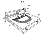
- FIG. 2 is a perspective view showing an example of a reinforcing fiber bundle arranging device 200 for producing the sheet-like reinforcing fiber substrate 1a.
- the reinforcing fiber bundle arranging device 200 includes an arrangement table 205 that is movable in the X-axis direction and supports the reinforcing fiber bundle, and a head 210 that arranges the reinforcing fiber bundle on the arrangement table 205.
- the head 210 is movable in the Y axis direction and the Z axis direction with respect to the arrangement table 205.
- the X axis direction, the Y axis direction, and the Z axis direction are orthogonal to each other.
- the head 210 can send the reinforcing fiber bundle to an arbitrary position on the arrangement table 205, and cuts the reinforcing fiber bundle sent at an arbitrary position on the arrangement table 205. be able to.
- the Y axis direction coincides with the feeding direction of the reinforcing fiber bundle.
- the reinforcing fiber bundles are arranged side by side on the arrangement table 205 in the Y-axis direction.
- the reinforcing fiber bundle 2 is arranged in a sheet form by a reinforcing fiber bundle arranging device 200 that draws the reinforcing fiber bundle 2 in one direction and arranges the reinforcing fiber bundle 2 on the arrangement table 205 as shown in FIG.
- position the reinforcing fiber bundle 2 in one direction is illustrated.
- an apparatus capable of arranging reinforcing fiber bundles in an arbitrary direction can also be used.
- a sheet-like reinforcing fiber substrate can be produced more efficiently.
- each end of each of the arranged reinforcing fiber bundles 2 is cut at a predetermined position.
- the arranged reinforcing fiber bundles 2 are in the form of a sheet having a predetermined outer periphery.
- This outer peripheral shape is determined according to the shape of the target fiber-reinforced resin molded product.
- the outer peripheral shape of the arranged reinforcing fiber bundles 2 is a shape in which the shape of a three-dimensional fiber reinforced resin molded product is developed on a plane.
- the arranged reinforcing fiber bundles 2 maintain a sheet-like form by restraining the positions of at least adjacent reinforcing fiber bundles 2 with each other.
- the restraining method of the reinforcing fiber bundle 2 is not limited, adhesion by a binder of a resin component can be used.
- “restraint” as used in the present specification includes a mode in which displacement of each position is hardly allowed and a mode in which displacement of each position within a predetermined range is allowed.
- FIG. 3A is a plan view showing an embodiment of a method for restraining the positions of adjacent reinforcing fiber bundles 2 in the sheet-like reinforcing fiber substrate 1.
- FIG. 3B is a cross-sectional view showing the structure of the sheet-like reinforcing fiber substrate 1 constrained by the constraining method of FIG. 3A.
- 3A to 6B exemplify structures applied not only to the sheet-like reinforcing fiber substrate 1a shown in FIG. 1 but also to various sheet-like reinforcing fiber substrates. For this reason, in FIG. 3A to FIG. 6B, the sheet-like reinforcing fiber base material is denoted by reference numeral “1”.
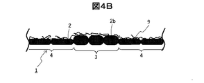
- the reinforcing fiber bundles 2 are arranged and arranged, and a powdery resin binder 8 is sprayed, and then heat is applied to melt and cool and solidify the powder. As a result, a part of the adjacent reinforcing fiber bundles 2 can be bonded to each other.
- the reinforcing fiber bundles 2b are arranged at a narrower interval than the other reinforcing fiber bundles 2.
- the reinforcing fiber bundles 2b have a cross-sectional shape that is narrower and thicker than the cross-sectional shapes of the other reinforcing fiber bundles 2.
- This is a bundle of reinforcing fibers.
- the reinforcing fiber bundle 2 represents not only the reinforcing fiber bundle having a cross-sectional shape that is wider and thinner than the reinforcing fiber bundle 2b, but also represents the entire reinforcing fiber bundle including the reinforcing fiber bundle 2b.
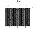
- FIG. 4A is a plan view showing another aspect of a method for constraining the positions of adjacent reinforcing fiber bundles 2 in the sheet-like reinforcing fiber substrate 1.
- FIG. 4B is a cross-sectional view showing the structure of the sheet-like reinforcing fiber substrate 1 constrained by the constraining method of FIG. 4A.
- adjacent reinforcing fiber bundles 2 can also be arranged by arranging and arranging reinforcing fiber bundles 2, spraying molten resin, and then cooling and solidifying in a fibrous form. Can be constrained to each other. 4A and 4B, the resin solidified in a fibrous form is denoted by reference numeral 9.
- the positions of the adjacent reinforcing fiber bundles 2 can be constrained to each other by arranging the reinforcing fiber bundles 2 to which the resin component has been added in advance on the surface, arranging the resin components, melting the resin component, and then solidifying the resin component. it can.
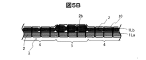
- FIG. 5A is a plan view showing another aspect of a further method of constraining the positions of adjacent reinforcing fiber bundles 2 in the sheet-like reinforcing fiber substrate 1.
- FIG. 5B is a cross-sectional view showing the structure of the sheet-like reinforcing fiber substrate 1 constrained by the constraining method of FIG. 5A.
- the sheet-like reinforcing fiber substrate 1 shown in FIGS. 5A and 5B has a two-layer structure in which a second layer 1Lb is formed on the first layer 1La.
- the number of layers when producing the sheet-like reinforcing fiber substrate 1 is generally smaller than the number of sheet-like reinforcing fiber substrates 1 when the sheet-like reinforcing fiber substrate 1 is laminated. For this reason, alignment of the layers in the sheet-like reinforcing fiber base 1 can be performed with high accuracy. Therefore, the precision of the position of the layers in the fiber reinforced resin molded product produced
- the reinforcing fiber bundles 2 arranged in an aligned manner can be engaged by sewing with the auxiliary thread 10.
- the material of the auxiliary yarn 10 is not limited, but glass fiber, polyester fiber, nylon fiber, or the like can be used. As long as the positions of adjacent reinforcing fiber bundles 2 can be constrained to each other, the type of thread, the engagement method, and the like are not limited.
- Such a method of engaging the reinforcing fiber bundle 2 by stitching is particularly effective when two or more layers of reinforcing fibers are laminated as shown in FIG. 5B.
- two or more layers are arranged so that the longitudinal direction Ld of the reinforcing fibers is aligned in one direction, and two or more layers are laminated so that the longitudinal directions Ld of the reinforcing fiber bundles 2 are different from each other. This is realized by restraining the positions of the reinforcing fiber bundles 2 to be overlapped and the overlapping reinforcing fiber bundles 2 to each other.
- the binding force between the reinforcing fiber bundles 2 is too weak, the handleability deteriorates.
- the binding force between the reinforcing fiber bundles 2 is too strong, there is an adverse effect on the deformation of the sheet-like reinforcing fiber substrate 1 when the sheet-like reinforcing fiber substrate 1 is shaped, which is not preferable. For this reason, the restraint form and conditions in which restraint force becomes moderate are preferable.
- the amount of reinforcing fibers in the second portion 3 of the first layer 1La is equal to the amount of reinforcing fibers in the first portion 4.
- the first portion and the second portion of the second layer 1Lb may be referred to as “third portion” and “fourth portion”, respectively.
- the third portion of the second layer 1Lb is provided in a range overlapping with the first portion 4 of the first layer 1La.
- the fourth portion of the second layer 1Lb is provided in a range overlapping with the second portion 3 of the first layer 1La.
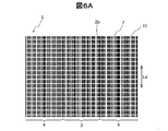
- FIG. 6A is a plan view showing still another aspect of the method of restraining the positions of adjacent reinforcing fiber bundles 2 in the sheet-like reinforcing fiber base 1.
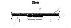
- FIG. 6B is a cross-sectional view showing the structure of the sheet-like reinforcing fiber base material 1 constrained by the constraining method of FIG. 6A.
- the cloth-like material 11 is affixed to the reinforcing fiber bundle 2.
- a nonwoven fabric, a woven fabric, or a knitted fabric can be used as the cloth-like product 11.
- the thing stuck on the reinforcing fiber bundle 2 has a predetermined size (area) in the two-dimensional direction, and may be anything that can be bonded to the arranged reinforcing fiber bundles 2.
- the material of a cloth-like thing or a mesh-like thing is not specifically limited.
- a thermoplastic resin material is used as the material for the cloth or mesh
- a restraining force can be generated by softening or melting the resin.
- a cloth-like thing and a mesh-like thing can also be stuck on the reinforcing fiber bundle 2 using an adhesive agent.
- the cloth-like material or mesh-like material has less influence on the physical properties of the fiber-reinforced resin molded product when the basis weight is smaller. Moreover, since the thing excellent in the deformability is hard to inhibit the shaping property of the sheet-like reinforcing fiber substrate 1, it is preferable.
- the amount of reinforcing fibers disposed is partially increased.
- the part 3 to be partially increased is set corresponding to the part where mechanical properties such as strength and rigidity are to be reinforced in the design requirements of the fiber reinforced resin member.
- One mode in which the amount of reinforcing fibers disposed is partially increased is shown in FIG.
- a portion of the sheet-like reinforcing fiber substrate 1 a where the weight of reinforcing fibers per unit area is small is shown as a first portion 4, and the weight of reinforcing fibers per unit area is higher than that of the first portion 4.
- the larger part is shown as the second part 3.
- the mode in which the amount of reinforcing fibers disposed is partially increased is not limited to the mode in FIG.
- part which should be reinforced in the sheet-like reinforcing fiber base material 1a is decided by the design requirements of a member, and there exist various aspects, such as a peripheral part, a center part, and local.
- a portion constituting a portion having a strength higher than that of the portion constituted by the first portion 4 of the sheet-like reinforcing fiber base 1a is used as the second portion of the sheet-like reinforcing fiber base 1a. It can be part 3.
- a portion constituting a portion having higher rigidity than a portion constituted by the first portion 4 of the sheet-like reinforcing fiber base 1a is designated as the second portion of the sheet-like reinforcing fiber base 1a. It can be part 3. “Strength” is evaluated by the magnitude of the load when the target part is destroyed when a load is applied to the target part of the fiber reinforced resin molded product under the same conditions and the load is gradually increased. To do. The “rigidity” is evaluated by the amount of distortion of the target portion when a load is applied to the target portion of the fiber-reinforced resin molded product under the same conditions.
- a portion constituting a portion having a curvature larger than the curvature of the portion constituted by the first portion 4 of the sheet-like reinforcing fiber base 1a is designated as the first of the sheet-like reinforcing fiber base 1a. 2 part 3.
- a portion having a larger curvature is more likely to be greatly deformed (elongated) during molding. For this reason, in such a part, the density of the reinforcing fiber may be lowered.
- the reinforcing part may extend over most of the sheet-like reinforcing fiber.
- the amount of reinforcing fibers disposed is partially reduced, that is, in the first portion 4.
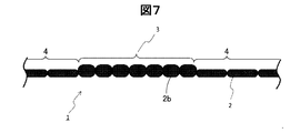
- FIG. 7 is a cross-sectional view showing an embodiment of a method for partially increasing the amount of reinforcing fibers of a sheet-like reinforcing fiber base.
- FIG. 7 conceptually shows a cross-sectional structure corresponding to the AA cross section of FIG. 7 to 9 do not accurately reflect the dimensions of each part.
- 7 to 9 exemplify structures that are not limited to the sheet-like reinforcing fiber substrate 1a shown in FIG. 1, but are applicable to various sheet-like reinforcing fiber substrates. Therefore, also in FIGS. 7 to 9, the sheet-like reinforcing fiber base material is indicated by the reference numeral “1”.
- a method of narrowing the pitch for arranging the reinforcing fiber bundles 2b in the second portion 3 for increasing the amount of the reinforcing fibers can be adopted as shown in FIG. .
- the interval between the reinforcing fiber bundles 2 b is small, so that the cross-sectional shape of the reinforcing fiber bundle 2 b is larger than the cross-sectional shape of the reinforcing fiber bundle 2 of the first portion 4.
- the shape is narrow and thick.
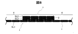
- FIG. 8 is a cross-sectional view showing another aspect of a method for partially increasing the amount of reinforcing fibers of a sheet-like reinforcing fiber base.
- FIG. 8 conceptually shows a cross-sectional structure corresponding to the AA cross section of FIG.
- a method of increasing the arrangement density of the reinforcing fiber bundles 2 by, for example, arranging the reinforcing fiber bundles 2 in the second portion 3 where the amount of reinforcing fibers is increased may be employed.
- the sheet-like reinforcing fiber base 1 is not provided in the first partial layer SL1 provided in the first portion 4 and the second portion 3 and in the first portion 4 and in the second portion.
- the second partial layers SL2 and SL2 provided in the portion 3 of FIG. Since the first partial layer SL1 and the second partial layer SL2 are formed of the same reinforcing fiber bundle 2, the weights of the reinforcing fibers per unit area are both constant and equal.
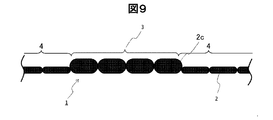
- FIG. 9 is a cross-sectional view showing still another aspect of a method for partially increasing the amount of reinforcing fibers of a sheet-like reinforcing fiber base.
- FIG. 9 conceptually shows a cross-sectional structure corresponding to the AA cross section of FIG. As shown in FIG. 9, so-called thick yarn having a larger number of single yarns constituting the reinforcing fiber bundle than the reinforcing fiber bundle 2 arranged in the first portion 4 as the reinforcing fiber bundle 2 c arranged in the second portion 3.
- a method using can be adopted.
- a method using a fine yarn in which the number of single yarns constituting the reinforcing fiber bundle is less than that of the reinforcing fiber bundle arranged in the second portion 3 is also adopted. Yes. Also, two or more of the methods described with reference to FIGS. 7 to 9 can be used in combination.
- FIGS. 3A to 4B and FIGS. 7 to 9 the reinforcing fibers are aligned so that the longitudinal direction Ld thereof is one direction.
- the sheet-like reinforcing fiber base material 1 can be generated by arranging them and restraining the reinforcing fibers together.
- Such a sheet-like reinforcing fiber base includes one layer of reinforcing fibers 1La.
- the reinforcing fiber bundle 2 is formed by arranging the layers arranged so that the longitudinal direction Ld of the reinforcing fibers is one direction. Two or more layers may be laminated such that the longitudinal directions Ld are different from each other, and (ii) the positions of the adjacent reinforcing fiber bundles 2 and the overlapping reinforcing fiber bundles 2 can be constrained to each other.
- FIGS. 5A and 5B show a first layer 1La and a second layer 1Lb in which the direction Ld of the reinforcing fiber bundle 2 is different.
- adjacent refers not only to the state in which the reinforcing fiber bundles 2 in the same sheet-like reinforcing fiber base material are arranged in parallel and adjacent to each other, but also in contact with each other when the sheet-like reinforcing fiber base materials are laminated. This includes a state in which the reinforcing fiber bundles constituting the two sheet-like reinforcing fiber substrates (1La and 1Lb in FIG. 5B) are adjacent to each other (adjacent in the stacking direction). That is, “adjacent” of the reinforcing fiber bundles is a relationship between two reinforcing fiber bundles, and represents a relationship in which no other reinforcing fiber bundle exists between the two reinforcing fiber bundles.
- the “overlapping reinforcing fiber bundle” is not limited to the relationship between two reinforcing fiber bundles adjacent to each other in the stacking direction, but includes three or more reinforcing fiber bundles composed of a set of reinforcing fiber bundles adjacent to each other in the stacking direction. Also represents group relationships.
- the following An effect is obtained. That is, it is possible to reduce the number of laminating operations when a plurality of sheet-like reinforcing fiber base materials are laminated to produce a reinforcing fiber base material and further the reinforcing fiber base materials are laminated. Further, since the reinforcing fiber bundles 2 in two different directions are constrained to each other in one sheet-like reinforcing fiber base material, when the reinforcing fiber base material is molded to obtain a preform, the sheet-like reinforcing fiber base material is used. The possibility that the material frays or the position of the reinforcing fiber bundle 2 is shifted can be reduced. As a result, the form of the reinforcing fiber base can be more stably maintained.
- Preparation of a sheet-like reinforcing fiber base material having such a multilayer structure can be realized in the following manner.
- the reinforcing fiber bundles 2 are arranged in one direction, and then the reinforcing fiber bundles 2 are arranged so as to be in another direction. Thereafter, the positions of the reinforcing fiber bundles 2 are constrained to each other.
- an intermediate product is prepared in which the reinforcing fiber bundles 2 are arranged in one direction and the positions of the adjacent reinforcing fiber bundles 2 are constrained to each other. Then, after stacking two or more such intermediate products, the positions of the overlapping reinforcing fiber bundles 2 are restrained by a binder or a stitch to obtain a sheet-like reinforcing fiber substrate having a multilayer structure.
- the fiber reinforced resin molded product it is also preferable to perform the following treatment. That is, when shaping along the shape of the fiber-reinforced resin molded product, the position of the reinforcing fiber bundle 2 constituting the sheet-like reinforcing fiber base is shifted in order to deform from a planar shape to a three-dimensional shape. As a result, the amount of reinforcing fibers disposed may be reduced. A part where such a situation is expected in the reinforcing fiber base is specified in advance. Then, the amount of reinforcing fibers disposed in advance in the portion of the sheet-like reinforcing fiber base corresponding to such a portion of the reinforcing fiber base is larger than that in other portions (see FIGS. 7 to 9).
- the reinforcing fiber base is shaped into a shape with large irregularities, the amount of reinforcing fibers placed in a part of the reinforcing fiber base decreases as a result of shaping, and as a result, the mechanical properties as designed can be obtained. It may disappear. However, by performing the above-described processing, the necessary amount of reinforcing fiber arrangement can be maintained even after shaping, so that the mechanical characteristics as designed can be exhibited.
- Two or more sheet-like reinforcing fiber bases including at least one such sheet-like reinforcing fiber base material are laminated to form a reinforcing fiber base material, which is shaped in substantially the same shape as the fiber-reinforced resin molded product.
- a preform can be produced by fixing the shape.
- the fiber-reinforced resin molded article of the embodiment of the present invention is molded using these sheet-like reinforcing fiber bases and preforms.
- a specific method for producing a fiber-reinforced resin molded product will be described with reference to the drawings.
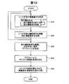
- FIG. 10 is a flowchart showing a process for manufacturing a fiber-reinforced resin molded product.
- step S10 a sheet-like reinforcing fiber base material is generated.
- step S12 the reinforcing fiber bundle arranging device 200 shown in FIG. 2 is used to arrange the reinforcing fiber bundles side by side so that the longitudinal directions Ld substantially coincide.
- the amount of reinforcing fibers in the second portion 3 is larger than the amount of reinforcing fibers in the first portion 4 by one or more of the methods described with reference to FIGS.
- a reinforcing fiber bundle is arranged (see also FIG. 1).
- step S12 adjacent reinforcing fiber bundles are constrained to each other by one or more of the methods described with reference to FIGS. 3A to 6B. As a result, for example, the unit layer 1La constituting the sheet-like reinforcing fiber base 1a shown in FIG. 1 is formed.
- the unit layer is formed (step S12) once or more.
- one or more new unit layers are formed in a region overlapping the already formed unit layer 1La.
- one or more new unit layers are formed in a region that matches the region of the unit layer 1La that has already been formed.
- At least one of the newly formed unit layers includes the reinforcing fiber bundle 2 having a different arrangement from the arrangement of the reinforcing fiber bundles 2 of the unit layer 1La that has already been formed (that is, the direction in the longitudinal direction Ld).
- the plurality of unit layers formed in step S10 can include two or more unit layers in which the arrangement of the reinforcing fiber bundles is the same.
- the second portions 3 having a large amount of reinforcing fibers in at least two or more unit layers are at least a part of each other. Are in the overlapping position. Further, in at least two or more unit layers, the first portions 4 having a small amount of reinforcing fibers are in positions where at least a part thereof overlaps.
- the first portion 4 and the second portion 3 of each unit layer may coincide with each other. preferable.
- step S10 at least a part of the reinforcing fiber bundles included in one unit layer 1La among the plurality of unit layers formed and at least a part of reinforcing fiber bundles included in the other unit layer 1Lb. Are constrained to each other at least in part (see, eg, FIGS. 5A and 5B). Thus, the sheet-like reinforcing fiber base material 1 including one or more unit layers is formed.
- Step S10 in FIG. 10 is performed once or more.
- at least one of the newly formed sheet-like reinforcing fiber bases is the arrangement of reinforcing fiber bundles of the sheet-like reinforcing fiber bases already formed (that is, The direction of the longitudinal direction Ld includes reinforcing fiber bundles having different arrangements.
- the plurality of sheet-like reinforcing fiber bases formed in step S10 can include two or more sheet-like reinforcing fiber bases having the same arrangement of reinforcing fiber bundles.
- the second part 3 having a large amount is in a position where at least a part of the second part 3 overlaps each other when the sheet-like reinforcing fiber base materials are laminated.
- the first portion 4 having a small amount of reinforcing fibers is located at a position where at least a part of each other overlaps when the sheet-like reinforcing fiber bases are laminated. is there.
- FIG. 11 is a plan view showing a sheet-like reinforcing fiber substrate 1b according to an embodiment of the present invention.
- FIG. 12 is a plan view showing a sheet-like reinforcing fiber substrate 1c according to an embodiment of the present invention.
- the sheet-like reinforcing fiber bases 1b and 1c are different from the sheet-like reinforcing fiber base 1a shown in FIG. 1 in the direction of the reinforcing fiber bundle 2.
- the other points of the sheet-like reinforcing fiber substrate 1b, 1c are the same as the sheet-like reinforcing fiber substrate 1a.
- the cross-sectional structures of the sheet-like reinforcing fiber bases 1a to 1c are as shown in FIG. 11 and 12, the components corresponding to the components shown in FIG. 1 are denoted by the same reference numerals.
- the first portion 4 and the second portion 3 of the sheet-like reinforcing fiber bases 1a to 1c coincide with each other when projected in the stacking direction.
- step S20 of FIG. 10 the sheet-like reinforcing fiber base material generated in step S10 (see FIGS. 1, 11, and 12) is laminated. As a result, a reinforcing fiber substrate is generated.
- the sheet-like reinforcing fiber substrate 1d is different from the sheet-like reinforcing fiber substrates 1a to 1c in the direction of the reinforcing fiber bundle 2.
- the other points of the sheet-like reinforcing fiber substrate 1d are the same as the sheet-like reinforcing fiber substrate 1a.
- the second portions 3 are arranged at positions overlapping each other. For this reason, in the reinforcing fiber substrate, the specific part corresponding to the second portion 3 includes more reinforcing fibers than the other parts.
- step S10 when step S10 is implemented only once, the reinforcing fiber substrate generated in step S20 is equal to the sheet-like reinforcing fiber substrate generated in step S10. That is, in such a case, processing is not performed in step S20.
- step S10 and step S20 in FIG. 10 are performed once or more. As a result, one or more reinforcing fiber substrates are produced.
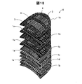
- FIG. 13 is a conceptual diagram showing a process of laminating the reinforcing fiber base material to generate the reinforcing fiber base material laminate 6.
- the reinforcing fiber base material generated in step S20 of FIG. 10 is an embodiment that is one of the sheet-like reinforcing fiber base materials 1a, 1b, 1c, 1d, that is, the sheet-like reinforcing fiber base material in step S20.
- stacking is not implemented is shown.
- step S30 of FIG. 10 as shown in FIG. 13, the reinforcing fiber bases (sheet-like reinforcing fiber bases 1a, 1b, 1c, 1d) generated in step S20 are laminated. As a result, the reinforcing fiber base laminate 6 is generated.
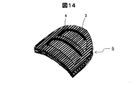
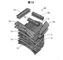
- FIG. 14 is a perspective view showing the reinforcing fiber base laminate 6.
- the second portions 3 are arranged at positions overlapping each other. For this reason, in the reinforcing fiber base laminate 6, the specific portion corresponding to the second portion 3 includes more reinforcing fibers than the other portions.
- step S30 in FIG. 10 the reinforcing fiber base laminate 6 is further shaped using a mold. That is, the reinforcing fiber base laminate 6 is molded from a planar shape to a three-dimensional shape without being subjected to removal processing such as cutting. Then, the shape of the reinforcing fiber base laminate 6 is fixed to the shape by the binder. As a result, a preform is formed.
- step S40 the preform is placed in the mold. Then, after the mold is closed, a liquid resin such as an epoxy resin is injected into the mold. This resin functions as a matrix resin in a finished fiber reinforced resin molded product.
- step S50 the resin impregnated in the preform is cured. As a result, a fiber reinforced resin molded product is generated.
- the resin that fixes the relative position of the reinforcing fiber is referred to as “matrix resin” in the present specification.
- the matrix resin includes not only the resin used in S50 of FIG. 10 but also the resins used in S10, S20, and S40 of FIG.
- FIG. 15 is a conceptual diagram showing a method for producing the reinforcing fiber base laminate 6C in the comparative example.
- the cut base materials 1p, 1q, 1r, and 1s having substantially the same outer shape are stacked.
- reinforcing cut base materials 12p to 12t are further laminated in accordance with the shape of the portion to be reinforced.
- the reinforcing cut base materials 12p to 12t are produced by cutting out from a reinforcing fiber base material having a predetermined width and basis weight.
- the cut base materials 12p to 12t for reinforcement are cut out from the reinforcing fiber base material having a certain width and basis weight generated in advance. For this reason, the base material which is not used generate
- the sheet-like reinforcing fiber base material of the present embodiment a structure in which the layer of the sheet-like reinforcing fiber base material whose outer shape is determined according to the shape of the fiber-reinforced resin molded product is also arranged for reinforcement Both are formed without going through a cutting step (see FIG. 2). For this reason, (i) The material discarded when producing a fiber reinforced resin molded product can be reduced. (Ii) The reinforcement of the fiber-reinforced resin molded product can be realized without increasing the material to be discarded.
- the sheet-like reinforced fiber base material according to the embodiment of the present invention can be suitably used in order to efficiently produce a fiber reinforced resin molded article having excellent lightweight and mechanical properties with high quality.
Landscapes
- Engineering & Computer Science (AREA)
- Mechanical Engineering (AREA)
- Chemical & Material Sciences (AREA)
- Composite Materials (AREA)
- Textile Engineering (AREA)
- Robotics (AREA)
- Reinforced Plastic Materials (AREA)
- Casting Or Compression Moulding Of Plastics Or The Like (AREA)
- Laminated Bodies (AREA)
- Moulding By Coating Moulds (AREA)
Abstract
Description
(1)強化繊維束をその長手方向が一方向となるように引き揃えて配置し、隣接する強化繊維束同士の位置を互いに拘束させてシート状の形態を保持させたシート状強化繊維基材であって、前記シート状強化繊維基材内において、強化繊維の配置量が部分的に増量され、単位面積あたりの強化繊維配置重量が非一様であることを特徴とする、シート状強化繊維基材。
(1)本発明の一形態によれば、繊維強化樹脂成形品を生成するためのシート状強化繊維基材が提供される。このシート状強化繊維基材は、長手方向が略同一となるように配された複数の強化繊維束であって、隣接する前記強化繊維束が少なくとも一部において互いに拘束されている複数の強化繊維束を含む第1の層を備える。前記第1の層は:複数の前記強化繊維束を含む第1の部分と;複数の前記強化繊維束を含み、単位面積あたりの強化繊維の重量が前記第1の部分よりも多い第2の部分と、を有する。
このような態様によれば、切り出し工程を経ずに、あらかじめ強化繊維の重量が多い部分を含んで構成されているシート状強化繊維基材を使用して、繊維強化樹脂成形品を生成することができる。このため、繊維強化樹脂成形品を作製する際に廃棄される材料を削減することができる。また、廃棄される材料を増やすことなく、繊維強化樹脂成形品の補強を実現することができる。さらに、繊維強化樹脂成形品の成形に際して、正確な位置を補強することができる。
このような態様においては、シート状強化繊維基材が複数層を含んで構成される。このため、繊維強化樹脂成形品を生成するためにシート状強化繊維基材を積層する際の工程の数を減らすことができる。
このような態様とすれば、同一の強化繊維束を使用した作業を複数回、行うことにより、シート状強化繊維基材において、第1の部分と第2の部分とを生成することができる。このため、第1の部分と第2の部分の生成が容易である。
このような態様としても、シート状強化繊維基材の一部について、強化繊維の量を多くすることができる。
このような態様とすれば、同一の強化繊維束を使用しつつ、強化繊維束の配置間隔を変えることにより、シート状強化繊維基材において、第1の部分と第2の部分とを生成することができる。このため、第1の部分と第2の部分の生成が容易である。
このような態様とすれば、繊維強化樹脂成形品の設計要件に応じて、シート状強化繊維基材の一部について、強化繊維の量を多くすることができる。
このような態様とすれば、繊維強化樹脂成形品において、高い強度や高い剛性を求められる部位に対応する部分について、シート状強化繊維基材の強化繊維の量を多くすることができる。
このような態様とすれば、シート状強化繊維基材の変形に従って単位面積当たりの強化繊維の重量が低減する部位において、他の部位に比べて大きく単位面積当たりの強化繊維の重量が低減しないように、あらかじめシート状強化繊維基材を生成する際に、対応する部位において強化繊維の量を多くすることができる。
繊維強化樹脂成形品において曲率が大きい部位は、繊維強化樹脂成形品の生成に当たって大きく変形および伸長することが予想される部位である。上記のような態様とすれば、そのような部位において、他の部位に比べて大きく単位面積当たりの強化繊維の重量が低減しないように、あらかじめシート状強化繊維基材を生成する際に、対応する部位において強化繊維の量を多くすることができる。
このような態様とすれば、シート状強化繊維基材内の任意の方向について近接している強化繊維束を、容易に拘束することができる。
このような態様とすれば、縫合の手法を適切に設定することにより、シート状強化繊維基材内の任意の方向について近接している強化繊維束を、拘束することができる。
このような態様のシート状強化繊維基材によれば、軽量の繊維強化樹脂成形品を生成することができる。
このような態様においては、強化繊維基材が複数のシート状強化繊維基材を含んで構成される。このため、繊維強化樹脂成形品を生成するために強化繊維基材を積層する際の工程の数を減らすことができる。
このような態様とすれば、強化繊維の量が増やされている部位が高精度に設けられている繊維強化樹脂成形品を得ることができる。
このような態様によれば、切り出し工程を経ずに、あらかじめ強化繊維の重量が多い部分を含んで構成されているシート状強化繊維基材を使用して、繊維強化樹脂成形品を生成することができる。このため、繊維強化樹脂成形品を作製する際に廃棄される材料を削減することができる。また、廃棄される材料を増やすことなく、繊維強化樹脂成形品の補強を実現することができる。さらに、繊維強化樹脂成形品の成形に際して、正確な位置を補強することができる。
このような態様においては、シート状強化繊維基材が複数層を含んで構成される。このため、繊維強化樹脂成形品を生成するためにシート状強化繊維基材を積層する際の工程の数を減らすことができる。
図1は、本発明の一実施態様に係るシート状強化繊維基材1aを示している。本発明の実施形態のシート状強化繊維基材1aにおいては、長手方向Ldが概ね同一方向となるように強化繊維束2が揃えて配置されている。その結果、シート状強化繊維基材1aは、揃えて配された強化繊維束2によってシート状に形成されている。
本発明の実施形態のシート状強化繊維基材を生成する際には、図3A~図4B、および図7~図9のように、強化繊維の長手方向Ldが一方向となるように引き揃えて配置し、強化繊維同士を拘束することによって、シート状強化繊維基材1を生成することができる。このようなシート状強化繊維基材は、1層の強化繊維1Laを含む。
以下では、図面を参照しつつ、具体的な繊維強化樹脂成形品の生産方法について説明する。
1La…単位層(第1の層)
1Lb…単位層(第2の層)
1p,1q,1r,1s…裁断基材
2,2b,2c…強化繊維束
3…第2の部分
4…第1の部分
6…強化繊維基材積層体
6C…強化繊維基材積層体
8…樹脂バインダー
9…繊維状樹脂
10…補助糸
11…布状物
12p~12t…裁断基材
200…強化繊維束配置装置
205…配置台
210…ヘッド
Ld…強化繊維の長手方向
SL1…第1の部分層
SL2…第2の部分層
Claims (23)
- 繊維強化樹脂成形品を生成するためのシート状強化繊維基材であって、
長手方向が略同一となるように配された複数の強化繊維束であって、隣接する前記強化繊維束が少なくとも一部において互いに拘束されている複数の強化繊維束を含む第1の層を備え、
前記第1の層は、
複数の前記強化繊維束を含む第1の部分と、
複数の前記強化繊維束を含み、単位面積あたりの強化繊維の重量が前記第1の部分よりも多い第2の部分と、を有する、シート状強化繊維基材。 - 請求項1記載のシート状強化繊維基材であって、さらに、
長手方向が略同一となるように配された複数の強化繊維束であって、隣接する強化繊維束が少なくとも一部において互いに拘束されている複数の強化繊維束を含む第2の層を備え、
前記第1と第2の層は、それぞれが含む複数の強化繊維束の長手方向が互いに異なるように積層されており、
前記第2の層に含まれる少なくとも一部の強化繊維束は、少なくとも一部において、前記第1の層に含まれる強化繊維束に拘束されており、
前記第2の層は、
少なくとも一部が前記第1の部分と重なる位置に配され、複数の前記強化繊維束を含む第3の部分と、
少なくとも一部が前記第2の部分と重なる位置に配され、複数の前記強化繊維束を含み、単位面積あたりの前記強化繊維の重量が前記第3の部分よりも多い第4の部分と、を有する、シート状強化繊維基材。 - 請求項1または2に記載のシート状強化繊維基材であって、
前記第1の層は、さらに、
前記第1の部分と前記第2の部分に設けられており、単位面積あたりの前記強化繊維の重量が一定である、第1の部分層と、
前記第1の部分には設けられておらず、前記第2の部分に設けられており、単位面積あたりの前記強化繊維の重量が一定である、第2の部分層と、を含む、シート状強化繊維基材。 - 請求項1または2に記載のシート状強化繊維基材であって、
前記第2の部分における前記強化繊維束は、前記第1の部分における前記強化繊維束よりも太い、シート状強化繊維基材。 - 請求項1または2に記載のシート状強化繊維基材であって、
前記第2の部分における前記複数の強化繊維束は、前記第1の部分における前記複数の強化繊維束の間隔よりも狭い間隔で配されている、シート状強化繊維基材。 - 請求項1から5のいずれか1項に記載のシート状強化繊維基材であって、
前記シート状強化繊維基材は、前記繊維強化樹脂成形品の形状に従って決定される外周形状を有しており、
前記第1および第2の部分は、前記繊維強化樹脂成形品の設計要件に従って決定されている、シート状強化繊維基材。 - 請求項1から5のいずれか1項に記載のシート状強化繊維基材であって、
前記第2の部分は、前記繊維強化樹脂成形品において、前記第1の部分が構成する部位よりも強度と剛性の少なくとも一方がより大きい部位を構成する部分である、シート状強化繊維基材。 - 請求項1から5のいずれか1項に記載のシート状強化繊維基材であって、
前記シート状強化繊維基材は、前記繊維強化樹脂成形品の形状に従って決定される外周形状を有しており、
前記第2の部分は、前記繊維強化樹脂成形品の形状に応じて前記シート状強化繊維基材を賦形する際に、前記シート状強化繊維基材の変形に従って単位面積当たりの強化繊維の重量が低減する部位である、シート状強化繊維基材。 - 請求項1から5のいずれか1項に記載のシート状強化繊維基材であって、
前記第2の部分は、前記繊維強化樹脂成形品において、前記第1の部分が構成する部位の曲率よりも大きい曲率を有する部位を構成する部分である、シート状強化繊維基材。 - 請求項1から9のいずれか1項に記載のシート状強化繊維基材であって、
隣接する前記強化繊維束は、樹脂バインダーによって互いに拘束されている、シート状強化繊維基材。 - 請求項1から9のいずれか1項に記載のシート状強化繊維基材であって、
隣接する前記強化繊維束は、補助糸によって縫合されている、シート状強化繊維基材。 - 請求項1から11のいずれか1項に記載のシート状強化繊維基材であって、
前記強化繊維束は、炭素繊維で構成される、シート状強化繊維基材。 - プリフォームであって、
請求項1から12のいずれか1項に記載されたシート状強化繊維基材を含む2枚以上の強化繊維基材であって、立体形状に賦形され形状固着されている2枚以上の強化繊維基材を含む、プリフォーム。 - 繊維強化樹脂成形品であって、
硬化されたマトリクス樹脂が含浸されている、請求項13に記載のプリフォームを含む、繊維強化樹脂成形品。 - シート状強化繊維基材を用いて繊維強化樹脂成形品を生産する方法であって、
単位層を形成する工程であって、
長手方向が略同一となるように複数の強化繊維束を配する工程と、
隣接する前記強化繊維束を少なくとも一部において互いに拘束させる工程と、を備える単位層を形成する工程を備え、
前記複数の強化繊維束を配する工程は、
複数の前記強化繊維束を含む第1の部分と、
複数の前記強化繊維束を含み、単位面積あたりの強化繊維の重量が前記第1の部分よりも多い第2の部分と、を形成する工程を含む、方法。 - 請求項15記載の方法であって、さらに、
前記単位層を形成する工程を繰り返して、互いに重なる複数の前記単位層を形成する工程であって、互いの前記複数の強化繊維束の長手方向が異なる複数の単位層を形成する工程と、
前記複数の単位層のうちの一つの単位層に含まれる少なくとも一部の強化繊維束と、前記複数の単位層のうちの他の一つの単位層に含まれる少なくとも一部の強化繊維束とを、少なくとも一部において互いに拘束させる工程と、を備え、
前記複数の単位層のうちの少なくとも二つの単位層において、
それぞれの前記第1の部分は互いに少なくとも一部が重なり、
それぞれの前記第2の部分は互いに少なくとも一部が重なる、方法。 - 請求項15または16に記載の方法であって、
前記単位層を形成する工程は、
単位面積あたりの前記強化繊維の重量が一定である第1の部分層を、前記第1の部分と前記第2の部分に設ける工程と、
単位面積あたりの前記強化繊維の重量が一定である第2の部分層を、前記第1の部分には設けず、前記第2の部分に設ける工程と、を含む、方法。 - 請求項15または16に記載の方法であって、
前記第2の部分を形成する工程は、前記第1の部分を形成する前記強化繊維束よりも太い前記強化繊維束を使用して、前記第2の部分を形成する工程を含む、方法。 - 請求項15または16に記載の方法であって、
前記第2の部分を形成する工程は、前記第1の部分を形成する前記複数の強化繊維束よりもの間隔よりも狭い間隔で前記複数の強化繊維束を配する工程を含む、方法。 - 請求項15から19のいずれか1項に記載の方法であって、さらに、
前記繊維強化樹脂成形品の形状に従って前記シート状強化繊維基材の外形形状を決定する工程と、
前記繊維強化樹脂成形品の設計要件に従って前記第1および第2の部分を決定する工程と、を備える、方法。 - 請求項15から19のいずれか1項に記載の方法であって、さらに、
前記繊維強化樹脂成形品の形状に従って前記シート状強化繊維基材の外形形状を決定する工程と、
前記繊維強化樹脂成形品の形状に応じて前記シート状強化繊維基材を賦形する際に、前記シート状強化繊維基材の変形に従って単位面積当たりの強化繊維の重量が低減する部位を特定し、前記特定された部位を前記第2の部分として決定する工程と、を備える、方法。 - 請求項15から21のいずれか1項に記載の方法であって、
隣接する前記強化繊維束の拘束は、樹脂バインダーによって行われる、方法。 - 請求項15から21のいずれか1項に記載の方法であって、
隣接する前記強化繊維束の拘束は、補助糸による縫合によって行われる、方法。
Priority Applications (7)
| Application Number | Priority Date | Filing Date | Title |
|---|---|---|---|
| ES16764477T ES2803582T3 (es) | 2015-03-19 | 2016-03-14 | Sustrato de fibra reforzada en forma de lámina, preforma, artículo moldeado de plástico reforzado con fibra y método de producción de un producto moldeado de resina reforzada con fibra |
| JP2016518229A JP6733541B2 (ja) | 2015-03-19 | 2016-03-14 | シート状強化繊維基材、プリフォームおよび繊維強化樹脂成形品 |
| EP16764477.2A EP3272488B1 (en) | 2015-03-19 | 2016-03-14 | Sheet-shaped reinforced fiber substrate, preform, fiber reinforced plastic molded article and method of producing a fiber-reinforced resin molded product |
| US15/557,667 US10493657B2 (en) | 2015-03-19 | 2016-03-14 | Sheet-like reinforcing fiber base material, preform and fiber-reinforced resin molded product |
| KR1020177024491A KR102496240B1 (ko) | 2015-03-19 | 2016-03-14 | 시트상 강화 섬유 기재, 프리폼 및 섬유 강화 수지 성형품 |
| CN201680015641.1A CN107428033B (zh) | 2015-03-19 | 2016-03-14 | 片状增强纤维基材、预成型体及纤维增强树脂成型品 |
| RU2017131946A RU2719817C2 (ru) | 2015-03-19 | 2016-03-14 | Листовой основной материал из армирующего волокна, заготовка и формованный продукт из армированной волокном смолы |
Applications Claiming Priority (2)
| Application Number | Priority Date | Filing Date | Title |
|---|---|---|---|
| JP2015-056292 | 2015-03-19 | ||
| JP2015056292 | 2015-03-19 |
Publications (1)
| Publication Number | Publication Date |
|---|---|
| WO2016147646A1 true WO2016147646A1 (ja) | 2016-09-22 |
Family
ID=56918709
Family Applications (1)
| Application Number | Title | Priority Date | Filing Date |
|---|---|---|---|
| PCT/JP2016/001436 Ceased WO2016147646A1 (ja) | 2015-03-19 | 2016-03-14 | シート状強化繊維基材、プリフォームおよび繊維強化樹脂成形品 |
Country Status (8)
| Country | Link |
|---|---|
| US (1) | US10493657B2 (ja) |
| EP (1) | EP3272488B1 (ja) |
| JP (1) | JP6733541B2 (ja) |
| KR (1) | KR102496240B1 (ja) |
| CN (1) | CN107428033B (ja) |
| ES (1) | ES2803582T3 (ja) |
| RU (1) | RU2719817C2 (ja) |
| WO (1) | WO2016147646A1 (ja) |
Cited By (8)
| Publication number | Priority date | Publication date | Assignee | Title |
|---|---|---|---|---|
| IL259272A (en) * | 2017-08-11 | 2018-06-28 | Boeing Co | Further production of fibers with ties and related systems and methods |
| CN110191788A (zh) * | 2017-01-18 | 2019-08-30 | 三菱化学株式会社 | 纤维增强塑料的制造方法 |
| JPWO2018083735A1 (ja) * | 2016-11-01 | 2019-09-19 | 日産自動車株式会社 | 複合材料用強化基材、複合材料および複合材料用強化基材の製造方法 |
| JPWO2018083734A1 (ja) * | 2016-11-01 | 2019-09-26 | 日産自動車株式会社 | 複合材料用強化基材、複合材料および複合材料用強化基材の製造方法 |
| JP2020517501A (ja) * | 2017-04-25 | 2020-06-18 | ヘクセル レインフォースメンツ ユーケイ リミテッド | 局所的な強化材を備えたプリフォーム |
| JP2022054847A (ja) * | 2020-09-28 | 2022-04-07 | 三菱ケミカル株式会社 | 繊維基材、炭素繊維強化複合材料、及び繊維基材の製造方法 |
| WO2022185918A1 (ja) | 2021-03-02 | 2022-09-09 | リンテック株式会社 | プリフォーム構造体、繊維強化プラスチック、及びプリフォーム構造体の製造方法 |
| JP2022189196A (ja) * | 2021-06-10 | 2022-12-22 | トヨタ紡織株式会社 | 構造体及びその使用方法 |
Families Citing this family (5)
| Publication number | Priority date | Publication date | Assignee | Title |
|---|---|---|---|---|
| US10730236B2 (en) | 2017-08-02 | 2020-08-04 | Ethicon Llc | System and method for additive manufacture of medical devices |
| DE102018109212B4 (de) * | 2018-04-18 | 2025-06-05 | Deutsches Zentrum für Luft- und Raumfahrt e.V. | Verfahren und Anlage zum Herstellen einer Faserpreform sowie Verfahren zur Herstellung eines Faserverbundbauteils |
| ES2980681T3 (es) * | 2018-11-30 | 2024-10-02 | Toray Industries | Material a base de fibra reforzada con conformación laminar y método de fabricación para el mismo |
| CN115335211B (zh) * | 2020-03-30 | 2025-03-25 | 东丽株式会社 | 纤维铺放装置 |
| WO2025247746A1 (en) | 2024-05-30 | 2025-12-04 | Icotec Ag | Method for manufacturing a medical bone connecting device |
Citations (4)
| Publication number | Priority date | Publication date | Assignee | Title |
|---|---|---|---|---|
| JPS56159156A (en) * | 1980-05-13 | 1981-12-08 | Mitsubishi Rayon Co | Wheel in fiber reinforced plastic and its manufacture |
| JPH05278032A (ja) * | 1992-02-07 | 1993-10-26 | Nippon Steel Corp | 一方向プリプレグと炭素繊維強化樹脂複合材料及びそれらの製造方法 |
| JPH08337666A (ja) * | 1995-06-13 | 1996-12-24 | Toray Ind Inc | プリフォームおよびその製造方法 |
| JP2002128921A (ja) * | 2000-10-30 | 2002-05-09 | Toho Tenax Co Ltd | 段差防止用プリプレグ、それを用いた管状体の製造方法および管状体 |
Family Cites Families (7)
| Publication number | Priority date | Publication date | Assignee | Title |
|---|---|---|---|---|
| TW252128B (ja) | 1992-02-07 | 1995-07-21 | Nippon Steel Corp | |
| JP4491968B2 (ja) * | 1999-03-23 | 2010-06-30 | 東レ株式会社 | 複合炭素繊維基材、プリフォームおよび炭素繊維強化プラスチックの製造方法 |
| JP3894035B2 (ja) * | 2001-07-04 | 2007-03-14 | 東レ株式会社 | 炭素繊維強化基材、それからなるプリフォームおよび複合材料 |
| ES2705448T3 (es) * | 2006-02-28 | 2019-03-25 | Toray Industries | Proceso para la producción de laminados de material base de fibra de refuerzo |
| US9475258B2 (en) | 2012-06-15 | 2016-10-25 | The Boeing Company | Multiple-resin composite structures and methods of producing the same |
| JP6132186B2 (ja) * | 2013-02-19 | 2017-05-24 | 東レ株式会社 | プリフォーム作製用基材の製造方法と装置、および、プリフォームと繊維強化プラスチックの製造方法 |
| WO2015002019A1 (ja) * | 2013-07-01 | 2015-01-08 | 日本ゼオン株式会社 | 延伸フィルムの製造方法 |
-
2016
- 2016-03-14 EP EP16764477.2A patent/EP3272488B1/en active Active
- 2016-03-14 KR KR1020177024491A patent/KR102496240B1/ko active Active
- 2016-03-14 ES ES16764477T patent/ES2803582T3/es active Active
- 2016-03-14 RU RU2017131946A patent/RU2719817C2/ru active
- 2016-03-14 US US15/557,667 patent/US10493657B2/en active Active
- 2016-03-14 JP JP2016518229A patent/JP6733541B2/ja active Active
- 2016-03-14 WO PCT/JP2016/001436 patent/WO2016147646A1/ja not_active Ceased
- 2016-03-14 CN CN201680015641.1A patent/CN107428033B/zh active Active
Patent Citations (4)
| Publication number | Priority date | Publication date | Assignee | Title |
|---|---|---|---|---|
| JPS56159156A (en) * | 1980-05-13 | 1981-12-08 | Mitsubishi Rayon Co | Wheel in fiber reinforced plastic and its manufacture |
| JPH05278032A (ja) * | 1992-02-07 | 1993-10-26 | Nippon Steel Corp | 一方向プリプレグと炭素繊維強化樹脂複合材料及びそれらの製造方法 |
| JPH08337666A (ja) * | 1995-06-13 | 1996-12-24 | Toray Ind Inc | プリフォームおよびその製造方法 |
| JP2002128921A (ja) * | 2000-10-30 | 2002-05-09 | Toho Tenax Co Ltd | 段差防止用プリプレグ、それを用いた管状体の製造方法および管状体 |
Non-Patent Citations (1)
| Title |
|---|
| See also references of EP3272488A4 * |
Cited By (20)
| Publication number | Priority date | Publication date | Assignee | Title |
|---|---|---|---|---|
| US11173687B2 (en) | 2016-11-01 | 2021-11-16 | Nissan Motor Co., Ltd. | Reinforced substrate for composite material, composite material, and method for manufacturing reinforced substrate for composite material |
| JPWO2018083735A1 (ja) * | 2016-11-01 | 2019-09-19 | 日産自動車株式会社 | 複合材料用強化基材、複合材料および複合材料用強化基材の製造方法 |
| JPWO2018083734A1 (ja) * | 2016-11-01 | 2019-09-26 | 日産自動車株式会社 | 複合材料用強化基材、複合材料および複合材料用強化基材の製造方法 |
| EP3536840A4 (en) * | 2016-11-01 | 2019-11-27 | Nissan Motor Co., Ltd. | COMPOSITIONAL REINFORCING SUBSTRATE, COMPOSITE AND METHOD FOR PRODUCING A COMPOSITIONAL REINFORCING SUBSTRATE |
| EP3536839A4 (en) * | 2016-11-01 | 2019-11-27 | Nissan Motor Co., Ltd. | REINFORCING SUBSTRATE FOR COMPOSITE, COMPOSITE AND METHOD FOR PRODUCING COMPOSITE REINFORCING SUBSTRATE |
| US11203178B2 (en) | 2016-11-01 | 2021-12-21 | Nissan Motor Co., Ltd. | Reinforced substrate for composite material, composite material, and method for manufacturing reinforced substrate for composite material |
| CN110191788A (zh) * | 2017-01-18 | 2019-08-30 | 三菱化学株式会社 | 纤维增强塑料的制造方法 |
| CN110191788B (zh) * | 2017-01-18 | 2021-07-13 | 三菱化学株式会社 | 纤维增强塑料的制造方法 |
| CN112936911A (zh) * | 2017-01-18 | 2021-06-11 | 三菱化学株式会社 | 纤维增强塑料的制造方法 |
| US11660785B2 (en) | 2017-01-18 | 2023-05-30 | Mitsubishi Chemical Corporation | Method for manufacturing fiber-reinforced plastic |
| JP7208158B2 (ja) | 2017-04-25 | 2023-01-18 | ヘクセル レインフォースメンツ ユーケイ リミテッド | 局所的な強化材を備えたプリフォーム |
| JP2020517501A (ja) * | 2017-04-25 | 2020-06-18 | ヘクセル レインフォースメンツ ユーケイ リミテッド | 局所的な強化材を備えたプリフォーム |
| EP3441212A1 (en) * | 2017-08-11 | 2019-02-13 | The Boeing Company | Additive manufacturing fiber tows with bindments |
| IL259272A (en) * | 2017-08-11 | 2018-06-28 | Boeing Co | Further production of fibers with ties and related systems and methods |
| JP2022054847A (ja) * | 2020-09-28 | 2022-04-07 | 三菱ケミカル株式会社 | 繊維基材、炭素繊維強化複合材料、及び繊維基材の製造方法 |
| WO2022185918A1 (ja) | 2021-03-02 | 2022-09-09 | リンテック株式会社 | プリフォーム構造体、繊維強化プラスチック、及びプリフォーム構造体の製造方法 |
| JPWO2022185918A1 (ja) * | 2021-03-02 | 2022-09-09 | ||
| JP7836292B2 (ja) | 2021-03-02 | 2026-03-26 | リンテック株式会社 | プリフォーム構造体、繊維強化プラスチック、及びプリフォーム構造体の製造方法 |
| JP2022189196A (ja) * | 2021-06-10 | 2022-12-22 | トヨタ紡織株式会社 | 構造体及びその使用方法 |
| JP7746697B2 (ja) | 2021-06-10 | 2025-10-01 | トヨタ紡織株式会社 | 構造体及びその使用方法 |
Also Published As
| Publication number | Publication date |
|---|---|
| US10493657B2 (en) | 2019-12-03 |
| RU2017131946A (ru) | 2019-04-03 |
| EP3272488A1 (en) | 2018-01-24 |
| KR20170129715A (ko) | 2017-11-27 |
| KR102496240B1 (ko) | 2023-02-06 |
| CN107428033A (zh) | 2017-12-01 |
| EP3272488A4 (en) | 2018-11-07 |
| RU2017131946A3 (ja) | 2019-07-24 |
| JP6733541B2 (ja) | 2020-08-05 |
| CN107428033B (zh) | 2019-12-24 |
| RU2719817C2 (ru) | 2020-04-23 |
| US20180093397A1 (en) | 2018-04-05 |
| EP3272488B1 (en) | 2020-05-06 |
| JPWO2016147646A1 (ja) | 2017-12-28 |
| ES2803582T3 (es) | 2021-01-28 |
Similar Documents
| Publication | Publication Date | Title |
|---|---|---|
| JP6733541B2 (ja) | シート状強化繊維基材、プリフォームおよび繊維強化樹脂成形品 | |
| JP6132186B2 (ja) | プリフォーム作製用基材の製造方法と装置、および、プリフォームと繊維強化プラスチックの製造方法 | |
| EP2554348B1 (en) | Method for laminating fiber-reinforced thermoplastic resin prepreg | |
| JP2009537691A (ja) | 成形材料 | |
| JP2011516752A (ja) | 繊維プリフォームの製造方法 | |
| JP7087337B2 (ja) | 強化繊維基材、強化繊維積層体および繊維強化樹脂 | |
| KR102687854B1 (ko) | 3차원 인쇄된 열가소성 핀을 이용한 복합재의 강화 | |
| CN109923253A (zh) | 复合材料用增强基材、复合材料以及复合材料用增强基材的制造方法 | |
| JP2017159652A (ja) | 強化繊維積層シートおよび繊維強化樹脂成形体 | |
| KR20200068893A (ko) | 중공단면을 가진 섬유강화복합재료 및 이의 제조방법 | |
| WO2017212835A1 (ja) | 複合材部品用の強化基材、複合材部品およびそれらの製造方法 | |
| JP5655386B2 (ja) | 繊維強化プラスチック成形体の製造方法 | |
| JP6938987B2 (ja) | 強化繊維基材の製造方法、強化繊維プリフォームの製造方法および繊維強化複合材料成形体の製造方法 | |
| JP6460398B2 (ja) | Rtm成形方法 | |
| JP6439528B2 (ja) | 強化繊維基材の製造方法 | |
| JP6729712B2 (ja) | 複合材料用強化基材、複合材料および複合材料用強化基材の製造方法 | |
| JP7148442B2 (ja) | 積層体の製造方法 | |
| JP2024070037A (ja) | 複合材料製パネル構造体の製造方法 | |
| US12090743B2 (en) | Sheet-shaped reinforcing fiber substrate and manufacturing method therefor | |
| JP2025084310A (ja) | 強化繊維基材 | |
| JP2019157079A (ja) | 繊維強化複合材料成形品の製造方法 |
Legal Events
| Date | Code | Title | Description |
|---|---|---|---|
| ENP | Entry into the national phase |
Ref document number: 2016518229 Country of ref document: JP Kind code of ref document: A |
|
| 121 | Ep: the epo has been informed by wipo that ep was designated in this application |
Ref document number: 16764477 Country of ref document: EP Kind code of ref document: A1 |
|
| ENP | Entry into the national phase |
Ref document number: 20177024491 Country of ref document: KR Kind code of ref document: A |
|
| REEP | Request for entry into the european phase |
Ref document number: 2016764477 Country of ref document: EP |
|
| WWE | Wipo information: entry into national phase |
Ref document number: 15557667 Country of ref document: US |
|
| NENP | Non-entry into the national phase |
Ref country code: DE |
|
| WWE | Wipo information: entry into national phase |
Ref document number: 2017131946 Country of ref document: RU |