WO2016147618A1 - 電気式回転機 - Google Patents
電気式回転機 Download PDFInfo
- Publication number
- WO2016147618A1 WO2016147618A1 PCT/JP2016/001316 JP2016001316W WO2016147618A1 WO 2016147618 A1 WO2016147618 A1 WO 2016147618A1 JP 2016001316 W JP2016001316 W JP 2016001316W WO 2016147618 A1 WO2016147618 A1 WO 2016147618A1
- Authority
- WO
- WIPO (PCT)
- Prior art keywords
- case
- rotating machine
- rotor
- electric rotating
- coil
- Prior art date
- Legal status (The legal status is an assumption and is not a legal conclusion. Google has not performed a legal analysis and makes no representation as to the accuracy of the status listed.)
- Ceased
Links
Images


Classifications
-
- H—ELECTRICITY
- H02—GENERATION; CONVERSION OR DISTRIBUTION OF ELECTRIC POWER
- H02K—DYNAMO-ELECTRIC MACHINES
- H02K1/00—Details of the magnetic circuit
- H02K1/06—Details of the magnetic circuit characterised by the shape, form or construction
- H02K1/12—Stationary parts of the magnetic circuit
- H02K1/20—Stationary parts of the magnetic circuit with channels or ducts for flow of cooling medium
-
- E—FIXED CONSTRUCTIONS
- E02—HYDRAULIC ENGINEERING; FOUNDATIONS; SOIL SHIFTING
- E02F—DREDGING; SOIL-SHIFTING
- E02F9/00—Component parts of dredgers or soil-shifting machines, not restricted to one of the kinds covered by groups E02F3/00 - E02F7/00
- E02F9/20—Drives; Control devices
- E02F9/2058—Electric or electro-mechanical or mechanical control devices of vehicle sub-units
- E02F9/2062—Control of propulsion units
- E02F9/2075—Control of propulsion units of the hybrid type
-
- E—FIXED CONSTRUCTIONS
- E02—HYDRAULIC ENGINEERING; FOUNDATIONS; SOIL SHIFTING
- E02F—DREDGING; SOIL-SHIFTING
- E02F9/00—Component parts of dredgers or soil-shifting machines, not restricted to one of the kinds covered by groups E02F3/00 - E02F7/00
- E02F9/08—Superstructures; Supports for superstructures
- E02F9/10—Supports for movable superstructures mounted on travelling or walking gears or on other superstructures
- E02F9/12—Slewing or traversing gears
- E02F9/121—Turntables, i.e. structure rotatable about 360°
- E02F9/123—Drives or control devices specially adapted therefor
-
- E—FIXED CONSTRUCTIONS
- E02—HYDRAULIC ENGINEERING; FOUNDATIONS; SOIL SHIFTING
- E02F—DREDGING; SOIL-SHIFTING
- E02F9/00—Component parts of dredgers or soil-shifting machines, not restricted to one of the kinds covered by groups E02F3/00 - E02F7/00
- E02F9/20—Drives; Control devices
- E02F9/22—Hydraulic or pneumatic drives
- E02F9/2278—Hydraulic circuits
- E02F9/2296—Systems with a variable displacement pump
-
- F—MECHANICAL ENGINEERING; LIGHTING; HEATING; WEAPONS; BLASTING
- F04—POSITIVE - DISPLACEMENT MACHINES FOR LIQUIDS; PUMPS FOR LIQUIDS OR ELASTIC FLUIDS
- F04B—POSITIVE-DISPLACEMENT MACHINES FOR LIQUIDS; PUMPS
- F04B17/00—Pumps characterised by combination with, or adaptation to, specific driving engines or motors
- F04B17/03—Pumps characterised by combination with, or adaptation to, specific driving engines or motors driven by electric motors
-
- F—MECHANICAL ENGINEERING; LIGHTING; HEATING; WEAPONS; BLASTING
- F04—POSITIVE - DISPLACEMENT MACHINES FOR LIQUIDS; PUMPS FOR LIQUIDS OR ELASTIC FLUIDS
- F04B—POSITIVE-DISPLACEMENT MACHINES FOR LIQUIDS; PUMPS
- F04B53/00—Component parts, details or accessories not provided for in, or of interest apart from, groups F04B1/00 - F04B23/00 or F04B39/00 - F04B47/00
- F04B53/08—Cooling; Heating; Preventing freezing
-
- H—ELECTRICITY
- H02—GENERATION; CONVERSION OR DISTRIBUTION OF ELECTRIC POWER
- H02K—DYNAMO-ELECTRIC MACHINES
- H02K1/00—Details of the magnetic circuit
- H02K1/06—Details of the magnetic circuit characterised by the shape, form or construction
- H02K1/22—Rotating parts of the magnetic circuit
- H02K1/27—Rotor cores with permanent magnets
- H02K1/2706—Inner rotors
-
- H—ELECTRICITY
- H02—GENERATION; CONVERSION OR DISTRIBUTION OF ELECTRIC POWER
- H02K—DYNAMO-ELECTRIC MACHINES
- H02K9/00—Arrangements for cooling or ventilating
- H02K9/19—Arrangements for cooling or ventilating for machines with closed casing and closed-circuit cooling using a liquid cooling medium, e.g. oil
-
- F—MECHANICAL ENGINEERING; LIGHTING; HEATING; WEAPONS; BLASTING
- F04—POSITIVE - DISPLACEMENT MACHINES FOR LIQUIDS; PUMPS FOR LIQUIDS OR ELASTIC FLUIDS
- F04B—POSITIVE-DISPLACEMENT MACHINES FOR LIQUIDS; PUMPS
- F04B39/00—Component parts, details, or accessories, of pumps or pumping systems specially adapted for elastic fluids, not otherwise provided for in, or of interest apart from, groups F04B25/00 - F04B37/00
- F04B39/06—Cooling; Heating; Prevention of freezing
Definitions
- the present invention relates to an electric rotating machine configured by winding a plurality of coils around a stator core disposed around a rotor.
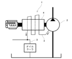
- the electric device 1 is provided in a hybrid excavator, and the hybrid excavator is driven by a hydraulic pump 2, an electric motor 4 that drives the hydraulic pump 2, and hydraulic oil discharged from the hydraulic pump 2, as shown in FIG.
- the hydraulic circuit (not shown) including the actuator unit to be operated and the cooling passage 3 into which drain oil (hydraulic oil) of the hydraulic pump 2 flows are provided.
- the drain oil of the hydraulic pump 2 is provided so as to flow into the cooling passage 3 and cool the electric motor 4, and can cool the electric motor 4 with higher cooling efficiency than the air cooling type.
- the coil wound around the stator core generates heat by the operation of the electric motor, and the generated heat is released from the case to the outside through the stator core. ing.
- An electrical insulation sheet is interposed between the coil and the stator core, and the electrical insulation sheet tends to have a contradiction in electrical insulation performance and heat transfer performance. Therefore, when the electrical insulation property of the electrical insulation sheet is improved, heat transmission is hindered by the electrical insulation sheet. Therefore, the generated heat of the coil is not easily released to the outside of the case, and how to cool the coil is important when downsizing or improving the performance of the electric motor.
- the present invention has been made to solve the above-described problems, and an object thereof is to provide an electric rotating machine that can improve the cooling performance of the coil.
- An electric rotating machine includes a case having an internal space, a rotor accommodated in the internal space of the case and rotatably supported by the case, and accommodated in the internal space of the case, and A stator core provided in the case with a space around the rotor, a plurality of coils wound around the stator core at a space in the circumferential direction, and the rotor and a part of the coil are immersed.
- a cooling liquid sealed in the inner space of the case is provided.
- the coolant in the case is agitated by centrifugal force and pushed toward the stator core.
- many coils provided in the stator core can be brought into contact with the coolant, and heat can be taken from the coils by the coolant.
- the heat deprived by the coolant is transmitted to the case indirectly or directly via the stator core, and can be released to the outside of the case via this case. That is, the heat of the coil can be released to the outside of the case through the coolant, the stator core, and the case, and the cooling performance of the coil can be improved.
- the coil can be cooled while ensuring the performance of the electrical insulation layer.
- the rotor is an upright type in which the rotation axis of the rotor is arranged substantially parallel to the vertical direction.
- the cooling liquid is pushed toward the stator core over the entire circumference of the rotor by the centrifugal force accompanying the rotation of the rotor, and the liquid level of the cooling liquid becomes a mortar shape.
- all of the plurality of coils can be immersed in the cooling liquid, and each coil can be entirely immersed in the cooling liquid.
- it is a plurality of coils, and each whole coil can be cooled efficiently.
- the coolant pushed toward the stator core by the centrifugal force rises along the inner surface of the case, and then flows toward the rotor while descending along the mortar-shaped liquid surface.
- the coolant is pushed again toward the inner surface of the case by centrifugal force.
- the coolant can be circulated in the internal space of the case, and by circulating, the coolant in the case can be prevented from locally becoming high temperature. Thereby, an electric rotary machine can be cooled efficiently.
- the amount of the cooling liquid sealed in the internal space of the case is greater than the amount of heat transfer per unit time in which the amount of heat released from the case per unit time is transmitted from the coil to the cooling liquid. It is preferable that the heat transfer amount per unit time is set to be a maximum value or a value close to the maximum value.
- the amount of the cooling liquid sealed in the internal space of the case is set to be larger than the heat transfer amount per unit time when the heat radiation amount per unit time from the case is transmitted from the coil to the cooling liquid.
- the entire amount of heat generated from the coil can be released to the outside through the coolant and the case.
- the heat absorption capacity of the coolant to the coil can be maximized by setting the amount of the coolant so that the amount of heat released from the case per unit time becomes the maximum value or a value close thereto. And a great cooling effect can be obtained for the coil.
- the electric rotating machine according to the present invention may be an electric motor, a generator, or an electric motor having a power generation function.
- This electric rotating machine can be applied to an electric motor, a generator, or an electric motor having a power generation function.
- the electric rotating machine may be a turning electric motor for construction machinery.
- Construction motor turning motors are effective for preventing overheating because they often start and stop repeatedly and generate a large amount of heat.
- the cooling performance of the coil can be improved.
- the electric rotating machine 11 can be applied to an electric motor, a generator, or an electric motor having a power generation function.
- the electric rotating machine 11 can be used for various machines and devices including construction machines.
- the electric rotating machine 11 is applied to an upright electric motor for turning of the construction machine 12 shown in FIG. Will be described.
- a hydraulic excavator is exemplified as the construction machine 12.
- the construction machine 12 can be applied to other cranes and the like, and the construction machine 12 is a hybrid type using hydraulic pressure and electricity. It may or may not be.
- a hydraulic excavator (construction machine) 12 shown in FIG. 4 is attached to a lower traveling body 13, an upper swinging body 14 that is turnably mounted on the lower traveling body 13, and the upper swinging body 14. And an excavation work machine 15 for performing the above.
- An electric rotating machine 11 is mounted on the upper swing body 14, and the electric rotating machine 11 is driven by electricity stored in a power storage device (not shown).
- the upper turning body 14 turns by the driving force of the electric rotating machine 11.
- the upper swing body 14 is also swung by a driving force of a hydraulic motor (not shown).
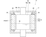
- This electric rotating machine 11 is, for example, an upright three-phase electric motor for turning as shown in FIG. 1, and the rotation speed is controlled by an inverter.
- the electric rotating machine 11 includes a rotor 16, a stator 17, a case 18, and a coolant 19.
- the rotor 16 has a rotating shaft 16a, and a cylindrical rotor body 16b is provided on the rotating shaft 16a. And both ends of the rotating shaft 16a are rotatably supported by the case 18 via bearings (not shown). And the rotating shaft 16a of this rotor 16 is arrange
- a stator 17 is disposed around the rotor 16 with an interval therebetween.
- the stator 17 is a so-called stator, and has a stator core 21 and a plurality of coils 22 in which thin steel plates are laminated.
- the stator core 21 has a yoke portion 21a and a plurality of teeth portions 21b.
- the yoke portion 21a is formed in a substantially cylindrical shape, and a plurality of teeth portions 21b are integrally provided on the inner peripheral surface of the yoke portion 21a.
- Each tooth part 21b protrudes inward in the radial direction from the inner peripheral surface of the yoke part 21a, and is formed long in the vertical direction.
- the teeth part 21b is arranged at equal intervals in the circumferential direction on the inner peripheral surface of the yoke part 21a, and the coil 22 is wound around each tooth part 21b via an electrical insulating sheet 23 having electrical insulation.
- Each of the plurality of coils 22 is arranged at equal intervals in the circumferential direction.
- the stator 17 configured as described above is fixed to the inner peripheral surface of the case 18.
- the inner peripheral surface of the case 18 is formed in a cylindrical shape centering on the rotating shaft 16 a of the rotor 16, and the stator 17 is disposed on the inner peripheral surface of the case 18 along the outer peripheral surface of the stator core 21. Yes.
- the rotor 16 and the stator 17 are accommodated in the inner space 18a of the case 18, and a predetermined amount of the cooling liquid 19 is further sealed therein.
- the cooling liquid 19 is a heat medium that takes heat generated from the coil 22 as a main heat source and transfers the heat to the stator core 21 and the case 18, and transfers the heat of the coil 22 to the case 18 indirectly or directly. To be released to the outside.
- the cooling liquid 19 is sealed in the inner space 18 a of the case 18, and a part of the rotor 16 and the stator 17 (more specifically, the lower end part of the rotor 16 and the coil 22) is immersed in the cooling liquid 19.
- an insulating oil having an electrically insulating performance is used in order to prevent conduction between various components, and the insulating performance of the insulating oil is preferably stable for a long time.
- the coolant 19 preferably has a low viscosity in the operating temperature range of the electric rotating machine 11. Thereby, the bubbles formed in the cooling liquid 19 can easily float on the liquid surface 19a, and the formation of bubbles in the liquid can be suppressed. Further, it is possible to easily eliminate the bubbles that have floated on the liquid surface 19a. Thereby, the fall of the cooling capability by a bubble can be suppressed. Further, the cooling liquid 19 may have an antifoaming property by adding an antifoaming agent to the insulating oil, and the cooling liquid 19 to which the antifoaming agent has been added has a cooling ability by air bubbles as described above. The decrease can be suppressed.
- the electric rotating machine 11 is an upright three-phase electric motor for turning as described above.
- the medium coolant 19 in the case 18 rotates in the same direction around the rotor 16 and is further centrifuged. Power is granted.
- the cooling liquid 19 is pushed toward the stator 17, and the liquid surface 19a of the cooling liquid 19 is formed in a mortar shape.
- each of the coils 22 is totally immersed in the cooling liquid 19 from the lower end portion to the upper end portion of each coil 22 in this embodiment, and the heat of the coil 22 is cooled from the entire coil 22 to the cooling liquid 19. Can be transmitted. Therefore, the entire coil 22 can be effectively cooled.
- the coolant 19 is circulated in the inner space 18 a of the case 18 by the rotation of the rotor 16. That is, the coolant 19 flows so as to be pushed from the rotor 16 toward the stator 17 in the vicinity of the rotor 16, and further flows upward along the coil 22 in the space between the yoke portion 21 a and the teeth portion 21 b of the stator core 21. . Further, the coolant 19 flows upward and enters the gap between the stator cores 21 and reaches the inner peripheral surface of the case 18 through the gap. Thereby, the coolant 19 expands the contact area with the inner peripheral surface of the case 18. Then, when it reaches the liquid level 19a, it flows toward the rotor 16 while descending along the liquid level 19a.
- the coolant 19 When returning to the rotor 16, the coolant 19 is again pushed toward the stator 17 by the rotor 16.
- the coolant 19 circulating in the inner space 18a takes heat from the coil 22 and further passes the taken heat directly to the case 18 or indirectly to the case 18 via the stator core 21. Release to the outside.
- the heat of the coil 22 can be released to the outside through the coolant 19 and the case 18, and the coil 22 can be efficiently Can be cooled to.
- heat can be taken from the rotor 16 and the stator core 21, and this heat can also be released to the outside through the case 18.
- the electric rotating machine 11 configured as described above, it is not necessary to provide a pipe or a passage for the coolant 19 close to the heat generating portion, and an inexpensive and compact electric rotating machine 11 can be manufactured. Further, since the cooling liquid 19 is sealed in the inner space 18 a of the case 18, the cooling liquid 19 is not heated from the outside of the electric rotating machine 11. Therefore, stable cooling characteristics can be realized in the electric rotating machine 11.
- the amount of heat per unit time transferred from the coil 22 to the coolant 19 and the amount of heat released per unit time from the case 18 are enclosed in the inner space 18a.
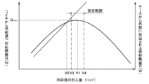
- the cooling liquid 19 changes depending on the amount of the cooling liquid 19. In the following, referring to FIG. 3, the amount V (m 3 ) of the coolant 19 in the electric rotating machine 11, the amount of heat Q (W) per unit time transferred from the coil 22 to the coolant 19, and the case The relationship of the amount of radiant heat R (W) per unit time released from 18 to the outside will be described.
- the change in the heat quantity Q per unit time with respect to the liquid volume V (m 3 ) of the cooling liquid 19 sealed in the case 18 from the coil 22 draws a parabola that becomes the maximum heat transfer quantity Q MAX when the predetermined liquid volume V1.
- the heat quantity Q per unit time transmitted from the coil 22 to the cooling liquid 19 is small even if the liquid quantity of the cooling liquid 19 is larger or smaller than the predetermined liquid volume V1.
- the change of the heat quantity Q per unit time transmitted from the coil 22 to the cooling liquid 19 with respect to the liquid volume V of the cooling liquid 19 draws a parabola, and when the liquid volume V becomes smaller than V1, the heat transfer quantity Q decreases. This is because the surface area of the coil 22 in contact with the coolant 19 is reduced. Further, when the liquid amount V exceeds V1, the amount of heat transferred from the coil 22 to the cooling liquid 19 due to the heat generated by the stirring of the cooling liquid 19 decreases.
- the amount of radiant heat R per unit time is, for example, heat generated in the coil 22 or the like by the current flowing in the coil 22 due to operation of the electric rotating machine 11, and heat generated by stirring the coolant 19 by the rotor 16.
- the amount of radiant heat R per unit time is proportional to the liquid volume V of the cooling liquid 19 in the case 18. Increase.
- the amount of heat transfer Q and the amount of radiant heat R per unit time having such characteristics are as follows. R exceeded. As a result, the amount of heat that can be released to the outside of the case 19 with respect to the heat generated in the coil 22 becomes small, and it may be difficult for the coil 22 to overheat and continue operation. Therefore, in the electric rotating machine 11, the liquid volume V of the cooling liquid 19 is set so that the heat quantity Q per unit time is smaller than the radiant heat quantity R per unit time, that is, the liquid volume V of the cooling liquid 19. Is preferably set to be V2 or more.
- the heat transfer amount Q per unit time becomes the maximum value Q MAX or a value close thereto (that is, a range in the vicinity of the maximum heat transfer amount Q MAX ).
- the liquid volume of the cooling liquid 19 is set so that the liquid volume V of the cooling liquid 19 is set within a setting range of V3 or more and V4 or less.
- the liquid volumes V3 and V4 are larger than the liquid volume V2 described above.
- the liquid volume V of the cooling liquid 19 in the case 18 is set to an amount when the heat transfer amount Q per unit time is smaller than the radiant heat amount R per unit time, thereby making the coil 22 efficient. Cooling is possible.
- the electric rotating machine 11 configured as described above can be adopted as a turning electric motor for the construction machine 12 including an electric excavator, for example. The electric motor for turning often repeats starting and stopping and generates a large amount of heat. However, by adopting the electric rotating machine 11, it can be effectively cooled and overheating can be prevented.
- the electric rotating machine 11 is applied to the electric motor.
- the electric rotating machine 11 can be applied to a generator or an electric motor having a power generation function instead.
Landscapes
- Engineering & Computer Science (AREA)
- General Engineering & Computer Science (AREA)
- Power Engineering (AREA)
- Mechanical Engineering (AREA)
- Mining & Mineral Resources (AREA)
- Civil Engineering (AREA)
- Structural Engineering (AREA)
- Motor Or Generator Cooling System (AREA)
- Operation Control Of Excavators (AREA)
Abstract
Description
このように構成される電気式回転機11は、例えば電動式ショベルを含む建設機械12の旋回用電動機として採用することができる。旋回用電動機は、起動及び停止を繰り返すことが多く発熱量が大きいが、当該電気式回転機11を採用することによって、効果的に冷却することができ、過熱の防止を図ることができる。
12 建設機械
13 下部走行体
14 上部旋回体
15 掘削作業機
16 ロータ
16a 回転軸
16b ロータ本体
17 ステータ
18 ケース
18a 内部空間
19 冷却液
21 ステータコア
22 コイル
Claims (5)
- 内部空間を有するケースと、
前記ケースの内部空間に収容され、且つ回転可能に前記ケースに支持されているロータと、
前記ケースの内部空間に収容され、且つ前記ロータの周囲に間隔を隔てて前記ケースに設けられているステータコアと、
周方向に互いに間隔をあけて前記ステータコアに巻き付けられている複数のコイルと、
前記ロータ及びコイルの一部分が浸かる状態となるように前記ケースの内側空間に封入されている冷却液とを備えていることを特徴とする電気式回転機。 - 前記ロータの回転軸が鉛直方向と略平行して配置される直立型であることを特徴とする請求項1記載の電気式回転機。
- 前記ケースの内部空間に封入される冷却液の液量は、前記ケースからの単位時間当たりの放熱量が、前記コイルから前記冷却液に伝達される単位時間当たりの伝熱量よりも大きく、且つ前記単位時間当たりの伝熱量が最大値又はそれに近い値となるように設定されていることを特徴とする請求項1又は2に記載の電気式回転機。
- 電動機、発電機、又は発電機能を有する電動機であることを特徴とする請求項1乃至3のいずれかに記載の電気式回転機。
- 建設機械の旋回用電動機であることを特徴とする請求項2又は3に記載の電気式回転機。
Priority Applications (4)
| Application Number | Priority Date | Filing Date | Title |
|---|---|---|---|
| CN201680015593.6A CN107408869A (zh) | 2015-03-13 | 2016-03-10 | 电气旋转机 |
| KR1020177027756A KR20170140183A (ko) | 2015-03-13 | 2016-03-10 | 전기식 회전기 |
| GB1716737.0A GB2553971A (en) | 2015-03-13 | 2016-03-10 | Electric rotary machine |
| US15/558,092 US20180051443A1 (en) | 2015-03-13 | 2016-03-10 | Electric rotating device |
Applications Claiming Priority (2)
| Application Number | Priority Date | Filing Date | Title |
|---|---|---|---|
| JP2015050800A JP2016171703A (ja) | 2015-03-13 | 2015-03-13 | 電気式回転機 |
| JP2015-050800 | 2015-03-13 |
Publications (1)
| Publication Number | Publication Date |
|---|---|
| WO2016147618A1 true WO2016147618A1 (ja) | 2016-09-22 |
Family
ID=56919606
Family Applications (1)
| Application Number | Title | Priority Date | Filing Date |
|---|---|---|---|
| PCT/JP2016/001316 Ceased WO2016147618A1 (ja) | 2015-03-13 | 2016-03-10 | 電気式回転機 |
Country Status (6)
| Country | Link |
|---|---|
| US (1) | US20180051443A1 (ja) |
| JP (1) | JP2016171703A (ja) |
| KR (1) | KR20170140183A (ja) |
| CN (1) | CN107408869A (ja) |
| GB (1) | GB2553971A (ja) |
| WO (1) | WO2016147618A1 (ja) |
Families Citing this family (4)
| Publication number | Priority date | Publication date | Assignee | Title |
|---|---|---|---|---|
| KR102463423B1 (ko) * | 2017-10-13 | 2022-11-03 | 현대자동차주식회사 | 자동차의 계자권선형 전기모터 |
| JP2019106776A (ja) * | 2017-12-12 | 2019-06-27 | 株式会社マーレ フィルターシステムズ | モータ内蔵型駆動装置 |
| FR3130471B1 (fr) * | 2021-12-13 | 2023-11-03 | Renault Sas | Carter pour machine électrique, machine électrique, circuit de refroidissement, véhicule et procédé de refroidissement associés |
| CN117751511B (zh) * | 2022-03-25 | 2025-03-11 | 广东逸动科技有限公司 | 电机、船用推进器及船舶 |
Citations (2)
| Publication number | Priority date | Publication date | Assignee | Title |
|---|---|---|---|---|
| JPS52147311A (en) * | 1976-06-02 | 1977-12-07 | Hitachi Ltd | Sealed type motor compressor |
| JP2014090553A (ja) * | 2012-10-29 | 2014-05-15 | Jtekt Corp | モータ |
Family Cites Families (11)
| Publication number | Priority date | Publication date | Assignee | Title |
|---|---|---|---|---|
| JPS61159583A (ja) * | 1984-12-29 | 1986-07-19 | Shin Etsu Chem Co Ltd | 冷却液組成物 |
| CN2187855Y (zh) * | 1994-04-29 | 1995-01-18 | 煤炭科学研究总院上海分院 | 充液冷却电机 |
| JP3501878B2 (ja) * | 1995-07-28 | 2004-03-02 | 日機装株式会社 | 冷却・潤滑系統を一体化した高速電動機 |
| US7352090B2 (en) * | 2004-03-19 | 2008-04-01 | Hamilton Sundstrand | Fluid-submerged electric motor |
| JP4586542B2 (ja) * | 2005-01-17 | 2010-11-24 | トヨタ自動車株式会社 | 回転電機 |
| JP5021443B2 (ja) * | 2007-12-14 | 2012-09-05 | 日立オートモティブシステムズ株式会社 | 回転電機 |
| JP4833237B2 (ja) * | 2008-03-03 | 2011-12-07 | 川崎重工業株式会社 | 電動機一体型油圧モータ |
| JP4883058B2 (ja) * | 2008-08-28 | 2012-02-22 | ダイキン工業株式会社 | 建設機械 |
| JP5290244B2 (ja) * | 2010-06-18 | 2013-09-18 | 株式会社小松製作所 | 建設機械の電動モータおよび電動モータの冷却回路 |
| JP5189185B2 (ja) * | 2011-06-20 | 2013-04-24 | 株式会社小松製作所 | 電動機 |
| KR20140078786A (ko) * | 2012-12-17 | 2014-06-26 | 주식회사 만도 | 냉각 구조를 갖는 모터 |
-
2015
- 2015-03-13 JP JP2015050800A patent/JP2016171703A/ja active Pending
-
2016
- 2016-03-10 GB GB1716737.0A patent/GB2553971A/en not_active Withdrawn
- 2016-03-10 WO PCT/JP2016/001316 patent/WO2016147618A1/ja not_active Ceased
- 2016-03-10 US US15/558,092 patent/US20180051443A1/en not_active Abandoned
- 2016-03-10 CN CN201680015593.6A patent/CN107408869A/zh active Pending
- 2016-03-10 KR KR1020177027756A patent/KR20170140183A/ko not_active Ceased
Patent Citations (2)
| Publication number | Priority date | Publication date | Assignee | Title |
|---|---|---|---|---|
| JPS52147311A (en) * | 1976-06-02 | 1977-12-07 | Hitachi Ltd | Sealed type motor compressor |
| JP2014090553A (ja) * | 2012-10-29 | 2014-05-15 | Jtekt Corp | モータ |
Also Published As
| Publication number | Publication date |
|---|---|
| CN107408869A (zh) | 2017-11-28 |
| US20180051443A1 (en) | 2018-02-22 |
| JP2016171703A (ja) | 2016-09-23 |
| GB2553971A (en) | 2018-03-21 |
| GB201716737D0 (en) | 2017-11-29 |
| KR20170140183A (ko) | 2017-12-20 |
Similar Documents
| Publication | Publication Date | Title |
|---|---|---|
| JP5908741B2 (ja) | 回転電機 | |
| JP5703698B2 (ja) | 回転機及び車両 | |
| JP5625565B2 (ja) | 回転機及び車両 | |
| JP6458436B2 (ja) | 車両用モータ装置 | |
| CN109314442B (zh) | 车辆用旋转电机 | |
| JP6628779B2 (ja) | 機電一体型回転電機装置 | |
| US10454344B2 (en) | Rotating electrical machine utilizing cooling liquid supplied to coil end to cool other components | |
| CN102891564B (zh) | 旋转电机 | |
| CN104412490B (zh) | 电动机 | |
| KR20120121758A (ko) | 전동기 및 이를 구비한 전기차량 | |
| CN103814515A (zh) | 机电一体型组件 | |
| JP2006353051A (ja) | 電動機の冷却装置 | |
| JP2016171703A (ja) | 電気式回転機 | |
| JP2014064433A (ja) | 回転電機のロータ軸 | |
| JP2019522456A (ja) | 電気モータ | |
| KR101412589B1 (ko) | 전동기 및 이를 구비한 전기차량 | |
| JP2012157098A (ja) | 回転電機の冷却装置 | |
| JP5801640B2 (ja) | 回転電機の固定子,回転電機,回転電機駆動システム及び電気自動車 | |
| JPH07231611A (ja) | 回転機の冷却構造 | |
| US8456044B2 (en) | Material matrix for cooling media enhancement | |
| KR101265131B1 (ko) | 전동기 및 이를 구비한 전기차량 | |
| CN218387063U (zh) | 电机及其轴承套 | |
| JP5678562B2 (ja) | モータの冷却装置 | |
| JP2020054065A (ja) | 車両 | |
| JP2005094846A (ja) | モータ |
Legal Events
| Date | Code | Title | Description |
|---|---|---|---|
| 121 | Ep: the epo has been informed by wipo that ep was designated in this application |
Ref document number: 16764450 Country of ref document: EP Kind code of ref document: A1 |
|
| WWE | Wipo information: entry into national phase |
Ref document number: 15558092 Country of ref document: US |
|
| NENP | Non-entry into the national phase |
Ref country code: DE |
|
| ENP | Entry into the national phase |
Ref document number: 20177027756 Country of ref document: KR Kind code of ref document: A |
|
| ENP | Entry into the national phase |
Ref document number: 201716737 Country of ref document: GB Kind code of ref document: A Free format text: PCT FILING DATE = 20160310 |
|
| 122 | Ep: pct application non-entry in european phase |
Ref document number: 16764450 Country of ref document: EP Kind code of ref document: A1 |